JP4401015B2 - Double rotary electronic components - Google Patents
Double rotary electronic components Download PDFInfo
- Publication number
- JP4401015B2 JP4401015B2 JP2000280165A JP2000280165A JP4401015B2 JP 4401015 B2 JP4401015 B2 JP 4401015B2 JP 2000280165 A JP2000280165 A JP 2000280165A JP 2000280165 A JP2000280165 A JP 2000280165A JP 4401015 B2 JP4401015 B2 JP 4401015B2
- Authority
- JP
- Japan
- Prior art keywords
- substrate
- rotary
- electronic component
- sliding contact
- support member
- Prior art date
- Legal status (The legal status is an assumption and is not a legal conclusion. Google has not performed a legal analysis and makes no representation as to the accuracy of the status listed.)
- Expired - Fee Related
Links
Images


Landscapes
- Switches With Compound Operations (AREA)
- Rotary Switch, Piano Key Switch, And Lever Switch (AREA)
Description
【0001】
【発明の属する技術分野】
本発明は、上下に二つの回転式電子部品を設置してなる二重回転式電子部品に関するものである。
【0002】
【従来の技術】
近年ビデオカメラやデジタルスチルカメラ等の携帯機器においては、その小型化のため、これを操作する各種スイッチ類を一箇所に集積化する傾向にある。例えば従来は所望の機能を操作するための回転つまみと、別の機能を操作するための回転つまみを機器の別々の場所に取り付けていたものを、一箇所にまとめて取り付ける必要が生じるようになってきた。
【0003】
このため二つの回転式電子部品を上下に二重に重ねて設置することが求められるが、そのためには基板を上下二段に設置しなければならず、上側の基板の回路をどこから機器本体側に引き出すか等、種々の解決しなければならない問題があり、またその小型化も困難であった。
【0004】
【発明が解決しようとする課題】
本発明は上述の点に鑑みてなされたものでありその目的は、回転式電子部品を上下二段に設置することができ、しかも構造が簡単で、小型化も図れる二重回転式電子部品を提供することにある。
【0006】
【課題を解決するための手段】
上記問題点を解決するため本発明にかかる二重回転式電子部品は、表面に第1摺接パターンを設けた第1基板上に第1回転型物を回転自在に設置してなる第1回転式電子部品と、表面に第2摺接パターンを設けた第2基板上に第2回転型物を回動自在に設置してなる第2回転式電子部品とを具備し、第1回転式電子部品の上に第2回転式電子部品を配置し、前記第1基板と第2基板は1枚のフレキシブルシート上に連結部を介してその両側の同一面上に第1摺接パターンと第2摺接パターンとを設けることで構成され、前記第1回転型物の中央に設けた開口内に挿入されて第1回転型物を回動自在に軸支する軸支部材を設置するとともに、この軸支部材の内部に前記連結部を挿通させる挿通部を設け、さらに前記軸支部材の下部に前記第1基板を前記第1摺接パターンが上向きとなるように載置する第1基板載置部材を設置し、前記軸支部材の上部に前記第2基板を前記第2摺接パターンが上向きとなるように載置する第2基板載置部材を設置したことを特徴とする。
【0008】
本発明によれば、軸支部材の内部に挿通部を設けたので、この軸支部材に第1回転型物を回動自在に軸支する機能と連結部を挿通させる機能とを併せ持たせることができる。
【0009】
【発明の実施の形態】
以下、本発明の実施形態を図面に基づいて詳細に説明する。
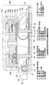
図1は本実施形態にかかる二重回転式電子部品の概略断面図、図2と図3は二重回転式電子部品の分解斜視図であり、両図を合わせて二重回転式電子部品全体の分解斜視図になるものである。
【0010】
図1に示すようにこの二重回転式電子部品は、第1回転式電子部品10の上に、第2回転式電子部品100を重ねるように配置して構成されている。具体的には、第1回転式電子部品10は、第1基台11上に、第1クリック板20と、第1基板30と、第1回転型物(回転つまみ)40と、軸支部材50とを取り付けて構成されている。一方第2回転式電子部品100は、第2基台110上に、第2基板120と、第2回転型物130と、第2クリック板140と、ケース150と、第2回転つまみ160とを取り付けて構成されている。以下各構成部品について説明する。
【0011】
第1基台11は合成樹脂を板状に成形して構成されており、その中央近傍には4つの小穴13が設けられている。またその上面の外周近傍からは押圧突起15が突出している。
【0012】
第1クリック板20は金属板製であり、前記第1基台11の四つの小穴13に対向する位置にそれぞれ小穴21を設け、またその所定位置に1つのクリック係合穴23を設けて構成されている。
【0013】
第1基板30はフレキシブル基板であり、略円弧状に形成されたシート部分の表面に所望のスイッチパターン(第1摺接パターン)31を設けて構成されている。第1基板30の根元部分にはこれを外部に引き出す引き出し部33と、下記する第2基板120に連結する連結部35とが反対方向に向けて引き出されている。第1基板30と連結部35の接続部分には、2つの固定用穴38が設けられている。
【0014】
図4は第1回転型物40及びこれに取り付ける部品を下面側から見た斜視図である。図3及び図4に示すように第1回転型物40は合成樹脂を略円板状に成形し、その中央に円形の開口41を設け、その上面の開口41の周囲に円弧状のストッパー収納部43を設け、一方その下面には開口41の周囲を囲むリング状のクリック板収納部45と、その半径方向外側に摺動子収納部44とを設け、さらにクリック板収納部45の外側に円弧状のコイルバネ収納部47と、コイルバネ収納部47に連続するように円弧状に延びる押圧突起収納部49とを設けて構成されている。またこの第1回転型物40は第1回転つまみでもあり、そのためその外周からは操作つまみ42が突出している。
【0015】
そしてクリック板収納部45には、弾性金属板をリング状に形成したクリック板60を収納し、その際クリック板収納部45に設けた小突起46をクリック板60に設けた小穴61に挿入してその先端を熱カシメすることで固定する。なおこのクリック板60の所定位置には弾発部63が設けられている。
【0016】
また摺動子収納部44には、弾性金属板製の第1摺動子70の基部71を収納し、その際摺動子収納部44に設けた小突起48を基部71に設けた小穴73に挿入してその先端を熱カシメすることで固定する。なお基部71の端部からはU字状に折り曲げられて突出する摺接部75が設けられている。
【0017】
更にコイルバネ収納部47にはコイルバネ80が収納されている。
【0018】
次に図2に示すように軸支部材50は合成樹脂成形品であり、略円板状の載置部51の下面から筒状の軸支部53を突出し、これによって軸支部53の中央に貫通する挿通部55を設けて構成されている。載置部51の外周近傍の三箇所には貫通する小穴57が設けられ、また載置部51上面にはその外周から挿通部55に至る凹状の基板収納部59が設けられている。なお載置部51の外周4箇所には、下記するケース150の4つの小突起154を挿入する凹部58が設けられている。
【0019】
ここで図5は軸支部材50を下面側から見た斜視図である。同図及び図2に示すように軸支部53の下端辺からは四本の小突起54が突出し、また載置部51の下面の所定位置には突起状のストッパー56が設けられている。
【0020】
図2に戻って第2基台110は、金属板を略円形に形成して構成されており、その中央には円形の穴111が設けられ、またその外周には下方向に向かって折り曲げられた三本の舌片状の係止片113が設けられ、また外周近傍の四箇所には小穴115が設けられている。
【0021】
第2基板120はフレキシブル基板であり、略円板状の部分の表面に所望のスイッチパターン(第2摺接パターン)121を設けて構成されている。第2基板120の外周からは前記第1基板30に接続される連結部35が突出している。第2基板120の中央には円形の穴123が設けられている。
【0022】
第2回転型物130は合成樹脂を略板状に成形して構成されており、その上面中央からは係止用突起部133が突出し、更にその中央からは円形の突起136が突出している。係止用突起部133の周囲には二つの切り欠き135が設けられ、その内部には小突起137が設けられている。また第2回転型物130の下面中央からも前記突起135と同様の突起138(図1参照)が突出している。係止用突起部133の上面には3つの貫通する円弧状の孔134が設けられている。またこの第2回転型物130の下面には、弾性金属板からなる第2摺動子170が固定される。第2摺動子170は前記第1摺動子70と同じ形状であり、同じ方法で第2回転型物130の下面に固定される。
【0023】
第2クリック板140は金属板をリング状に形成して構成されており、等間隔にクリック係合穴141を設け、また中央の孔143に向けて2つの舌片状の突起145を突出し、その中に小穴147を設けて構成されている。この第2クリック板140は第2回転型物130の上面に載置されることで、第2回転型物130の係止用突起部133が孔143に挿入され、その際各突起145は切り欠き135に係合され、小突起137は小孔147に挿入されて位置決めされる。
【0024】
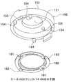
図6はケース150及びクリックバネ180を裏面側から見た斜視図である。同図及び図2に示すように、ケース150は合成樹脂を下面が開放された円形の箱型に成形して構成されており、その上面中央には貫通する穴151が設けられ、ケース150上面の外周辺部分にはストッパー挿入溝153が形成され、一方ケース150の外周下辺からは4つの小突起154を突出し、またケース150下面の穴151の周囲からも2つの小突起155を突出している。
【0025】
ケース150の下面には弾性金属板をリング状に形成してなるクリックバネ180が取り付けられるが、その際ケース150の2つの小突起155をクリックバネ180に設けた2つの穴181に挿入して熱カシメして固定する。クリックバネ180には2つの弾接部183が設けられている。
【0026】
図7は第2回転つまみ160を裏面側から見た斜視図である。この第2回転つまみ160は合成樹脂を円形に成形して構成され、その外周側面につまみ部161を設け、またその下面中央から三本の係止突起163を突出し、さらにその下面外周近傍部分にストッパー165を設けている。ストッパー165は図7では1つのみ示しているが、180度対向する位置にももう一つ設けている。この第2回転つまみ160は、その下面に凹部167を設けることで、第2回転つまみ160が第2回転型物130や第2摺動子170や第2基板120からなる第2回転式電子部品100の機能部の上部を覆うように構成されている。
【0027】
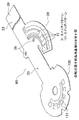
図8は第1基板30と第2基板120とを形成したフレキシブル基板製の回転式電子部品用基板90の斜視図である。同図に示すように第1基板30と第2基板120とは1枚のフレキシブルシート(例えばポリエチレンテレフタレート(PET)シート)の同一面上に、前述のように所望のスイッチパターン31,121を形成して構成されている。第2基板120と第1基板30とは帯状の連結部35によって連結され、第1基板30の連結部35の180°反対側からは引き出し部33が引き出され、その先端には電極部39が設けられている。各スイッチパターン31,121からは図示しない回路パターンが電極部39まで引き出されている。連結部35の第1基板30近傍部分には二つの固定用穴38が設けられている。
【0028】
ところで第1基板30は直線状に形成された連結部35及び引き出し部33の一方の側面から略円弧状に突出するように設けられている。そして連結部35は、第1基板30の真上に第2基板120を配置するように連結部35を湾曲させた際に、第1基板30に形成した円弧状のスイッチパターン31の円弧の中央付近で折れ曲がるように第1基板30に接続されている。
【0029】
次にこの二重回転式電子部品の組立方法を説明する。まず第2回転つまみ160の下面にクリックバネ180を取り付けたケース150を挿入し、第2回転つまみ160の係止突起163をケース150の穴151に回動自在に挿入して軸支する。
【0030】
次に第2摺動子170と第2クリック板140とを取り付けた第2回転型物130をケース150の下面に収納するが、その際第2回転つまみ160の3つの係止突起163を第2回転型物130の3つの孔134に挿入し、第2回転型物130の下面から突出した係止突起163先端を熱カシメすることで第2回転つまみ160と第2回転型物130とを一体に固定する。
【0031】
次に第2回転型物130の下側に第2基板120と第2基台110とを配置し、ケース150下面の各小突起154を第2基台110の各小穴115に挿入してその裏面側で熱カシメして固定する。このとき第2回転型物130の下面から突出する突起138は第2基板120の穴123と第2基台110の穴111に挿入されて回動自在に軸支される。
【0032】
次に回転式電子部品用基板90の引き出し部33と第1基板30の部分を軸支部材50の挿通部55内にその上側から挿通した上で、軸支部材50の載置部51上に第2基台110を載せ、各係止片113をそれぞれ各小穴57に挿入してその裏面で折り曲げて固定する。このとき連結部35は基板収納部59内を通っている。
【0033】
次にクリック板60と第1摺動子70とコイルバネ80とを取り付けた第1回転型物40の開口41に回転式電子部品用基板90の引き出し部33と第1基板30の部分をその上側から挿通し、さらに軸支部材50の軸支部53を開口41に挿入して回転自在に軸支し、次に第1回転型物40の下に第1基板30を位置せしめた状態でその下に第1クリック板20と第1基台11とを配置し、これによって軸支部材50に設けた4つの小突起54の内の二つを回転式電子部品用基板90の2つの固定用穴38に挿入し、さらに4つの小突起54を第1クリック板20に設けた四つの小穴21と第1基台11に設けた四つの小穴13に挿入してその先端を熱カシメし、これによってこの二重回転式電子部品の組立を完了する。このとき第1基台11の押圧突起15は第1回転型物40下面の押圧突起収納部49内に挿入されている。
【0034】
この二重回転式電子部品は図1に示すように、第1基板30上に第1回転型物40を回動自在に設置してなる第1回転式電子部品10と、第2基板120上に第2回転型物130を回動自在に設置してなる第2回転式電子部品100とを、第1回転型物40の回転中心軸と第2回転型物130の回転中心軸が同一軸となるように第1回転式電子部品10上に第2回転式電子部品100を配置し、さらに第2回転式電子部品100を回転操作する第2回転つまみ160によって第2回転式電子部品100の機能部を覆うように構成したので、多数の機能を有する二重回転式電子部品を少ない設置面積で機器に取り付けることができる。
【0035】
また1枚のフレキシブルシート上に連結部35を介してその両側に第1基板30と第2基板120を設け、連結部35の部分を第1回転型物40の回転中心部分に挿通させたので、第1回転型物40の上下に容易且つコンパクトに第2基板120と第1基板30とを設置することができる。
【0036】
次にこの二重回転式電子部品の動作を説明する。図1において上側の第2回転つまみ160を回転すればこれと一体に第2回転型物130が回転し、第2摺動子170が第2基板120のスイッチパターン121上を摺動してそのオンオフ状態を変化すると同時に、クリックバネ180の弾接部183が第2クリック板140のクリック係合穴141への挿入・離脱を繰り返すことでクリック感覚を生じる。なお第2回転型物130の回動範囲は、第2回転つまみ160に設けたストッパー165がケース150に設けたストッパー挿入溝153内を移動できる範囲である。
【0037】
一方操作つまみ42を押して回動することで第1回転型物40を一方の方向(コイルバネ80の端面を押圧する方向)に回転すると、押圧突起収納部49内に位置していた押圧突起15がコイルバネ80の一端面を押圧してコイルバネ80をコイルバネ収納部47内で圧縮して縮める。このとき第1摺動子70は第一基板30のスイッチパターン31上を摺動し、そのオンオフ状態を変化する。操作つまみ42の押圧を解除するとコイルバネ80の弾発力によって第1回転型物40は元の位置に自動復帰する。操作つまみ42を逆方向に押して第1回転型物40を回動すると第1摺動子70がスイッチパターン31上を摺動してそのオンオフ状態を変化すると同時に、第1回転型物40に取り付けたクリック板60の弾発部63が第1クリック板20のクリック係合穴23に係合し、その際クリック感覚が生じる。なお第1回転型物40は、クリック板60の弾発部63がクリック係合穴23に係合した位置よりも先には回動していかない。何故なら第1回転型物40の回動範囲は、軸支部材50に設けたストッパー56(図5参照)が第1回転型物40に設けたストッパー収納部43内を移動する範囲に規制されているからである。
【0038】
つまりこの二重回転式電子部品は、第2回転型物130を回転することで多数のスイッチが切り換わるように構成され、一方第1回転型物40は中立位置と、コイルバネ80を押圧しながら回動する位置と、反対方向に回動してクリック感覚を生じる位置の3ポジションでスイッチが切り換わるように構成されている。
【0039】
ところで第1基板30は組立の際に軸支部材50の挿通部55に挿入されるが、上記実施形態においては第1基板30を連結部35の一方の側面から円弧状に突出するように設けたので、容易にこれを湾曲することができてその挿入が容易に行なえる。
【0040】
また本発明においては、第1基板30と第2基板120を連結部35で連結した回転式電子部品用基板90を、略「Z」字状に折り曲げることで第1基板30上に第2基板120を配置したので、回転式電子部品用基板90上に形成する回路パターンは一方の面だけで良く、その製造が容易になる。特に上記実施形態では、第1基板30の真上に第2基板120を配置するように連結部35を湾曲せしめた際に、連結部35が第1基板30に形成した円弧状のスイッチパターン(第1摺接パターン)31の円弧の中央付近で折れ曲がるように構成したので、連結部35は挿通部55に容易に通すことができる。また連結部35を回転式電子部品の内部を通すので、回転式電子部品用基板90の途中の部分が外部に出ることはなく、小型化が図れる。
【0041】
以上本発明の実施形態を説明したが、本発明は上記実施形態に限定されるものではなく、特許請求の範囲、及び明細書と図面に記載された技術的思想の範囲内において種々の変形が可能である。なお直接明細書及び図面に記載がない何れの形状や構造や材質であっても、本願発明の作用・効果を奏する以上、本願発明の技術的思想の範囲内である。
【0043】
【発明の効果】
以上詳細に説明したように本発明によれば以下のような優れた効果を有する。
即ち、1枚のフレキシブルシート上に連結部を介してその両側に第1基板と第2基板を構成したので、部品点数の削減化が図れる。また連結部を軸支部材の挿通部に挿通させることで、軸支部材の下部に第1基板を、軸支部材の上部に第2基板を設置せしめたので、上側の第2基板の回路の引き出しを第1回転式電子部品と第2回転式電子部品の間から外部に引き出すことなく、従って小型化が図れ、構造も簡単になる。
【図面の簡単な説明】
【図1】本発明の一実施形態にかかる二重回転式電子部品の概略断面図である。
【図2】二重回転式電子部品の上半分の分解斜視図である。
【図3】二重回転式電子部品の下半分の分解斜視図である。
【図4】第1回転型物40及びこれに取り付ける部品を下面側から見た斜視図である。
【図5】軸支部材50を下面側から見た斜視図である。
【図6】ケース150とクリックバネ180を裏面側から見た斜視図である。
【図7】第2回転つまみ160を裏面側から見た斜視図である。
【図8】回転式電子部品用基板90の斜視図である。
【符号の説明】
10 第1回転式電子部品
11 第1基台(第1基板載置部材)
20 第1クリック板
30 第1基板
31 スイッチパターン(第1摺接パターン)
33 引き出し部
35 連結部
40 第1回転型物(回転つまみ)
41 開口
42 操作つまみ
50 軸支部材
51 載置部
53 軸支部
55 挿通部
70 第1摺動子
80 コイルバネ
90 回転式電子部品用基板
100 第2回転式電子部品
110 第2基台(第2基板載置部材)
120 第2基板
121 スイッチパターン(第2摺接パターン)
130 第2回転型物
140 第2クリック板
150 ケース
160 第2回転つまみ
170 第2摺動子[0001]
BACKGROUND OF THE INVENTION
The present invention relates to a double rotary electronic component in which two rotary electronic components are installed on the upper and lower sides.
[0002]
[Prior art]
In recent years, portable devices such as video cameras and digital still cameras tend to integrate various switches for operating them in one place in order to reduce the size. For example, in the past, a rotary knob for operating a desired function and a rotary knob for operating another function, which were attached to different locations, need to be attached together in one place. I came.
[0003]
For this reason, it is required to install two rotary electronic components in a vertical stack, but for that purpose, the board must be installed in two stages, upper and lower, and the circuit of the upper board from where the equipment body side There are various problems that need to be solved, such as whether or not to pull out them.
[0004]
[Problems to be solved by the invention]
SUMMARY OF THE INVENTION The present invention has been made in view of the above points, and an object of the present invention is to provide a double-rotating electronic component that can install rotating electronic components in two upper and lower stages, has a simple structure, and can be downsized. It is to provide.
[0006]
[Means for Solving the Problems]
In order to solve the above problems, the double-rotation electronic component according to the present invention has a first rotation in which a first rotation-type object is rotatably installed on a first substrate having a first sliding contact pattern on the surface. And a second rotary electronic component in which a second rotary type object is rotatably installed on a second substrate having a second sliding contact pattern on the surface, the first rotary electronic A second rotary electronic component is disposed on the component, and the first substrate and the second substrate are connected to the first sliding contact pattern and the second substrate on the same surface on both sides of the flexible substrate via a connecting portion on one flexible sheet. The sliding contact pattern is provided, and a shaft support member that is inserted into an opening provided in the center of the first rotary mold and pivotally supports the first rotary mold is installed. An insertion portion for inserting the connection portion is provided inside the shaft support member, and the first base is provided at a lower portion of the shaft support member. The first substrate placement member is placed so that the first sliding contact pattern faces upward, and the second substrate is placed on the pivot support member so that the second sliding contact pattern faces upward. A second substrate placement member to be placed is installed .
[0008]
According to the present invention, since the insertion portion is provided inside the shaft support member , the shaft support member is provided with both a function of pivotally supporting the first rotary mold and a function of inserting the connecting portion. be able to.
[0009]
DETAILED DESCRIPTION OF THE INVENTION
Hereinafter, embodiments of the present invention will be described in detail with reference to the drawings.
FIG. 1 is a schematic cross-sectional view of a double-rotation electronic component according to this embodiment, and FIGS. 2 and 3 are exploded perspective views of the double-rotation electronic component. It will become an exploded perspective view.
[0010]
As shown in FIG. 1, this double rotary electronic component is configured by arranging a second rotary
[0011]
The
[0012]
The
[0013]
The
[0014]
FIG. 4 is a perspective view of the first
[0015]
The click
[0016]
Further, the
[0017]
Further, a
[0018]
Next, as shown in FIG. 2, the
[0019]
Here, FIG. 5 is a perspective view of the
[0020]
Returning to FIG. 2, the
[0021]
The
[0022]
The second
[0023]
The
[0024]
FIG. 6 is a perspective view of the
[0025]
A
[0026]
FIG. 7 is a perspective view of the second
[0027]
FIG. 8 is a perspective view of a rotary
[0028]
Incidentally, the
[0029]
Next, a method for assembling the double rotary electronic component will be described. First, the
[0030]
Next, the second
[0031]
Next, the
[0032]
Next, the portion 33 of the rotary
[0033]
Next, the drawer portion 33 of the rotary
[0034]
As shown in FIG. 1, the double rotary electronic component includes a first rotary
[0035]
Also, since the
[0036]
Next, the operation of the double rotary electronic component will be described. In FIG. 1, if the second
[0037]
On the other hand, when the first
[0038]
That is, this double-rotating electronic component is configured such that a large number of switches are switched by rotating the second
[0039]
By the way, the
[0040]
Further, in the present invention, the
[0041]
Although the embodiments of the present invention have been described above, the present invention is not limited to the above-described embodiments, and various modifications can be made within the scope of the technical idea described in the claims and the specification and drawings. Is possible. Note that any shape, structure, or material not directly described in the specification and drawings is within the scope of the technical idea of the present invention as long as the effects and advantages of the present invention are exhibited.
[0043]
【The invention's effect】
As described in detail above, the present invention has the following excellent effects.
That is, since the first substrate and the second substrate are formed on both sides of the flexible sheet via the connecting portion on one flexible sheet, the number of components can be reduced. Further , by inserting the connecting portion through the insertion portion of the shaft support member , the first substrate is installed at the lower portion of the shaft support member and the second substrate is installed at the upper portion of the shaft support member . Without pulling out the drawer from between the first rotary electronic component and the second rotary electronic component, the size can be reduced and the structure can be simplified.
[Brief description of the drawings]
FIG. 1 is a schematic cross-sectional view of a double rotary electronic component according to an embodiment of the present invention.
FIG. 2 is an exploded perspective view of the upper half of the double-rotating electronic component.
FIG. 3 is an exploded perspective view of the lower half of the double-rotating electronic component.
FIG. 4 is a perspective view of a first
FIG. 5 is a perspective view of the
FIG. 6 is a perspective view of a
7 is a perspective view of the second
FIG. 8 is a perspective view of a
[Explanation of symbols]
10 1st rotary
20
33
41
120
130
Claims (2)
表面に第2摺接パターンを設けた第2基板上に第2回転型物を回動自在に設置してなる第2回転式電子部品とを具備し、
第1回転式電子部品の上に第2回転式電子部品を配置し、
前記第1基板と第2基板は1枚のフレキシブルシート上に連結部を介してその両側の同一面上に第1摺接パターンと第2摺接パターンとを設けることで構成され、
前記第1回転型物の中央に設けた開口内に挿入されて第1回転型物を回動自在に軸支する軸支部材を設置するとともに、この軸支部材の内部に前記連結部を挿通させる挿通部を設け、さらに前記軸支部材の下部に前記第1基板を前記第1摺接パターンが上向きとなるように載置する第1基板載置部材を設置し、前記軸支部材の上部に前記第2基板を前記第2摺接パターンが上向きとなるように載置する第2基板載置部材を設置したことを特徴とする二重回転式電子部品。A first rotary electronic component in which a first rotary type object is rotatably set on a first substrate having a first sliding contact pattern on the surface;
A second rotary electronic component in which a second rotary type object is rotatably installed on a second substrate having a second sliding contact pattern on the surface;
Placing the second rotary electronic component on the first rotary electronic component;
The first substrate and the second substrate are configured by providing a first sliding contact pattern and a second sliding contact pattern on the same surface on both sides of the flexible substrate via a connecting portion on one flexible sheet ,
A shaft support member is provided which is inserted into an opening provided in the center of the first rotary mold and pivotally supports the first rotary mold, and the connecting portion is inserted into the shaft support member. A first substrate placement member for placing the first substrate on the lower portion of the pivot support member so that the first sliding contact pattern faces upward, and an upper portion of the pivot support member. A double-rotating electronic component comprising: a second substrate mounting member for mounting the second substrate so that the second sliding contact pattern faces upward .
前記第1基板は、前記連結部の一方の側面から突出して設けられていることを特徴とする二重回転式電子部品。The double-rotating electronic component according to claim 1, wherein the first substrate is provided so as to protrude from one side surface of the connecting portion.
Priority Applications (1)
| Application Number | Priority Date | Filing Date | Title |
|---|---|---|---|
| JP2000280165A JP4401015B2 (en) | 2000-09-14 | 2000-09-14 | Double rotary electronic components |
Applications Claiming Priority (1)
| Application Number | Priority Date | Filing Date | Title |
|---|---|---|---|
| JP2000280165A JP4401015B2 (en) | 2000-09-14 | 2000-09-14 | Double rotary electronic components |
Publications (3)
| Publication Number | Publication Date |
|---|---|
| JP2002093279A JP2002093279A (en) | 2002-03-29 |
| JP2002093279A5 JP2002093279A5 (en) | 2007-04-26 |
| JP4401015B2 true JP4401015B2 (en) | 2010-01-20 |
Family
ID=18765057
Family Applications (1)
| Application Number | Title | Priority Date | Filing Date |
|---|---|---|---|
| JP2000280165A Expired - Fee Related JP4401015B2 (en) | 2000-09-14 | 2000-09-14 | Double rotary electronic components |
Country Status (1)
| Country | Link |
|---|---|
| JP (1) | JP4401015B2 (en) |
Families Citing this family (1)
| Publication number | Priority date | Publication date | Assignee | Title |
|---|---|---|---|---|
| JP2005019031A (en) * | 2003-06-23 | 2005-01-20 | Teikoku Tsushin Kogyo Co Ltd | Multiple rotary electronic component |
-
2000
- 2000-09-14 JP JP2000280165A patent/JP4401015B2/en not_active Expired - Fee Related
Also Published As
| Publication number | Publication date |
|---|---|
| JP2002093279A (en) | 2002-03-29 |
Similar Documents
| Publication | Publication Date | Title |
|---|---|---|
| JP4827830B2 (en) | Rotating electronic components | |
| JP4005766B2 (en) | Switch device | |
| JP3821696B2 (en) | Multiple rotary electronic components | |
| JP2008152966A (en) | Rotating body returning mechanism | |
| JPH0555432U (en) | Rotary electronic component with push button switch | |
| JP4401015B2 (en) | Double rotary electronic components | |
| JP4718429B2 (en) | Rotating electronic components | |
| JP4703526B2 (en) | Multifunctional electronic components | |
| JP2008071589A (en) | Multidirectional pressing type switch | |
| JP2019160812A (en) | Rotary electronic component with push switch | |
| JP4136625B2 (en) | Rotating electronic components | |
| JP4312041B2 (en) | Rotating electronic component with two-stage push switch | |
| JP4357091B2 (en) | Rotating electronic components with pushbutton switches | |
| JP3174900B2 (en) | Rotary electronic components with pushbutton switches | |
| JP2002181099A (en) | Compression coil spring | |
| JP2539073Y2 (en) | Rotary electronic components with pushbutton switches | |
| JP4471817B2 (en) | Multifunctional electronic components | |
| JP2005347234A (en) | Multi-directional pressing switch | |
| JP2007053029A (en) | Rotary electronic component with push switch mechanism | |
| JP2003178650A (en) | Electronic component | |
| JP3243682B2 (en) | Rotary electronic components | |
| JP6549979B2 (en) | Rotary electronic parts with pressure switch | |
| JP3052042B2 (en) | Composite electronic components | |
| JP2576364Y2 (en) | Rotary electronic components | |
| JP2001184967A (en) | Rotating electronic part |
Legal Events
| Date | Code | Title | Description |
|---|---|---|---|
| A521 | Written amendment |
Free format text: JAPANESE INTERMEDIATE CODE: A523 Effective date: 20070309 Free format text: JAPANESE INTERMEDIATE CODE: A821 Effective date: 20070309 |
|
| A621 | Written request for application examination |
Free format text: JAPANESE INTERMEDIATE CODE: A621 Effective date: 20070309 |
|
| A977 | Report on retrieval |
Free format text: JAPANESE INTERMEDIATE CODE: A971007 Effective date: 20090721 |
|
| A131 | Notification of reasons for refusal |
Free format text: JAPANESE INTERMEDIATE CODE: A131 Effective date: 20090728 |
|
| A521 | Written amendment |
Free format text: JAPANESE INTERMEDIATE CODE: A821 Effective date: 20090911 Free format text: JAPANESE INTERMEDIATE CODE: A523 Effective date: 20090911 |
|
| TRDD | Decision of grant or rejection written | ||
| A01 | Written decision to grant a patent or to grant a registration (utility model) |
Free format text: JAPANESE INTERMEDIATE CODE: A01 Effective date: 20091027 |
|
| A01 | Written decision to grant a patent or to grant a registration (utility model) |
Free format text: JAPANESE INTERMEDIATE CODE: A01 |
|
| A61 | First payment of annual fees (during grant procedure) |
Free format text: JAPANESE INTERMEDIATE CODE: A61 Effective date: 20091027 |
|
| R150 | Certificate of patent (=grant) or registration of utility model |
Free format text: JAPANESE INTERMEDIATE CODE: R150 |
|
| FPAY | Renewal fee payment (prs date is renewal date of database) |
Free format text: PAYMENT UNTIL: 20121106 Year of fee payment: 3 |
|
| FPAY | Renewal fee payment (prs date is renewal date of database) |
Free format text: PAYMENT UNTIL: 20121106 Year of fee payment: 3 |
|
| FPAY | Renewal fee payment (prs date is renewal date of database) |
Free format text: PAYMENT UNTIL: 20131106 Year of fee payment: 4 |
|
| LAPS | Cancellation because of no payment of annual fees |