JP4396699B2 - Body structure - Google Patents
Body structure Download PDFInfo
- Publication number
- JP4396699B2 JP4396699B2 JP2006340458A JP2006340458A JP4396699B2 JP 4396699 B2 JP4396699 B2 JP 4396699B2 JP 2006340458 A JP2006340458 A JP 2006340458A JP 2006340458 A JP2006340458 A JP 2006340458A JP 4396699 B2 JP4396699 B2 JP 4396699B2
- Authority
- JP
- Japan
- Prior art keywords
- bulkhead
- load
- reinforcing
- body structure
- absorbing member
- Prior art date
- Legal status (The legal status is an assumption and is not a legal conclusion. Google has not performed a legal analysis and makes no representation as to the accuracy of the status listed.)
- Expired - Fee Related
Links
Images


Classifications
-
- B—PERFORMING OPERATIONS; TRANSPORTING
- B62—LAND VEHICLES FOR TRAVELLING OTHERWISE THAN ON RAILS
- B62D—MOTOR VEHICLES; TRAILERS
- B62D25/00—Superstructure or monocoque structure sub-units; Parts or details thereof not otherwise provided for
- B62D25/02—Side panels
- B62D25/025—Side sills thereof
-
- B—PERFORMING OPERATIONS; TRANSPORTING
- B62—LAND VEHICLES FOR TRAVELLING OTHERWISE THAN ON RAILS
- B62D—MOTOR VEHICLES; TRAILERS
- B62D29/00—Superstructures, understructures, or sub-units thereof, characterised by the material thereof
- B62D29/001—Superstructures, understructures, or sub-units thereof, characterised by the material thereof characterised by combining metal and synthetic material
- B62D29/002—Superstructures, understructures, or sub-units thereof, characterised by the material thereof characterised by combining metal and synthetic material a foamable synthetic material or metal being added in situ
Landscapes
- Engineering & Computer Science (AREA)
- Chemical & Material Sciences (AREA)
- Combustion & Propulsion (AREA)
- Transportation (AREA)
- Mechanical Engineering (AREA)
- Architecture (AREA)
- Structural Engineering (AREA)
- Body Structure For Vehicles (AREA)
Description
本発明は、衝突などにより曲げ座屈が発生し易い部位に設けられる車体構造に関する。 The present invention relates to a vehicle body structure provided at a site where bending buckling is likely to occur due to a collision or the like.
従来の車体構造として、構造部材の壁面に、補強部材と、当該補強部材の長手方向の一端に対して所定の角度をなして対向するバルクヘッドとを設けたものが知られている(例えば、特許文献1)。このような車体構造によれば、衝突などにより構造部材に曲げ座屈が発生した場合に、補強部材の長手方向の一端とバルクヘッドを干渉させることによって、構造部材の車両内側への変形を抑えることができる。
しかし、上述の車体構造にあっては、補強部材の長手方向の一端とバルクヘッドの間は空間が形成されているため、それらが接触するまでの間は十分な衝撃吸収がなされず、結果として構造部材の変形量が増大するおそれがあった。 However, in the vehicle body structure described above, since a space is formed between one end of the reinforcing member in the longitudinal direction and the bulkhead, sufficient shock absorption is not performed until they come into contact with each other. There is a risk that the amount of deformation of the structural member increases.
本発明は、このような課題を解決するためになされたものであり、衝突などにより構造部材に曲げ座屈が発生した場合に、構造部材の曲げ変形の進行を抑制することのできる車体構造を提供することを目的とする。 The present invention has been made to solve such a problem, and a vehicle body structure capable of suppressing the progress of bending deformation of a structural member when bending buckling occurs in the structural member due to a collision or the like. The purpose is to provide.
本発明に係る車体構造は、内部空間を有する構造部材と、構造部材の内部空間に、構造部材の長手方向に並んで配置された少なくとも2つの補強部材と、2つの補強部材の間に配置され、補強部材が受けた荷重を吸収する荷重吸収部材と、を備えることを特徴とする。 A vehicle body structure according to the present invention is disposed between a structural member having an internal space, at least two reinforcing members arranged in the longitudinal direction of the structural member in the internal space of the structural member, and the two reinforcing members. And a load absorbing member that absorbs the load received by the reinforcing member.
この車体構造によれば、構造部材の内部において曲げ座屈の生じ易い位置を挟むように2つの補強部材を設けた場合、衝突などによりその位置で曲げ座屈が発生しても、2つの補強部材の間に配置された荷重吸収部材が、当該各補強部材に挟み込まれるとともに、各補強部材が受けた荷重を吸収する。これによって、構造部材は、補強部材を介して荷重吸収部材に荷重を吸収されながら変形することとなる。このとき、各補強部材の互いに対向する面同士の接近が荷重吸収部材によって抑制されるため、構造部材の変形の進行を抑制することができる。 According to this vehicle body structure, when two reinforcing members are provided so as to sandwich a position where bending buckling is likely to occur inside the structural member, even if bending buckling occurs at that position due to a collision or the like, the two reinforcing members A load absorbing member disposed between the members is sandwiched between the reinforcing members and absorbs the load received by the reinforcing members. As a result, the structural member is deformed while the load is absorbed by the load absorbing member via the reinforcing member. At this time, since the approach of the mutually opposing surfaces of each reinforcing member is suppressed by the load absorbing member, the progress of the deformation of the structural member can be suppressed.
また、本発明に係る車体構造は、荷重吸収部材が、バルクヘッドからなることが好ましい。このような構造によれば、荷重吸収部材であるバルクヘッドは、各補強部材に押し潰されることによって荷重を吸収することができる。更に、例えばバルクヘッドを形成する部材の厚み、材質などを変更することにより荷重吸収特性を容易に調整することができ、これによって構造部材の変形量を調整することができる。また、各補強部材の互いに対向する面がなす角度と距離とを変えることによっても、荷重吸収特性を調整し、構造部材の変形量を調整することができる。以上により、構造部材の最適な変形量を得ることができる。 In the vehicle body structure according to the present invention, the load absorbing member is preferably a bulkhead. According to such a structure, the bulkhead that is the load absorbing member can absorb the load by being crushed by each reinforcing member. Furthermore, for example, the load absorption characteristic can be easily adjusted by changing the thickness, material, and the like of the member forming the bulkhead, whereby the deformation amount of the structural member can be adjusted. Also, the load absorption characteristics can be adjusted and the deformation amount of the structural member can be adjusted by changing the angle and distance formed by the mutually opposing surfaces of the reinforcing members. As described above, an optimal amount of deformation of the structural member can be obtained.
また、本発明に係る車体構造は、荷重吸収部材が、弾性体からなることが好ましい。このような構造によれば、荷重吸収部材が弾性変形しながら荷重を受けることができる。更に、弾性体の弾性特性を変えることにより荷重吸収特性を容易に調整することができ、これによって構造部材の変形量を調整することができる。以上により、構造部材の最適な変形量を得ることができる。 In the vehicle body structure according to the present invention, the load absorbing member is preferably made of an elastic body. According to such a structure, the load absorbing member can receive a load while being elastically deformed. Furthermore, the load absorption characteristic can be easily adjusted by changing the elastic characteristic of the elastic body, and thereby the deformation amount of the structural member can be adjusted. As described above, an optimal amount of deformation of the structural member can be obtained.
また、本発明に係る車体構造は、荷重吸収部材が、切り欠き部を有することが好ましい。このような構造によれば、切り欠き部の大きさや形状を変えることにより荷重吸収特性を容易に調整することができ、これによって構造部材の変形量を調整することができる。従って、構造部材の最適な変形量を得ることができる。 In the vehicle body structure according to the present invention, the load absorbing member preferably has a notch. According to such a structure, the load absorption characteristic can be easily adjusted by changing the size and shape of the notch, and thereby the deformation amount of the structural member can be adjusted. Therefore, the optimal deformation amount of the structural member can be obtained.
本発明に係る車両構造は、構造部材がロッカであることが好ましい。この場合には、側面衝突時における衝撃吸収性能を向上させることができる。 In the vehicle structure according to the present invention, the structural member is preferably a rocker. In this case, the impact absorption performance at the time of a side collision can be improved.
このように、本発明によれば、衝突などにより構造部材に曲げ座屈が発生した場合に、構造部材の曲げ変形の進行を抑制することができる。その結果、衝突時の衝撃を車両全体で適切に吸収するとともに、構造部材の曲がりすぎによる車室内空間の圧迫を防止することができる。 Thus, according to the present invention, when bending buckling occurs in the structural member due to a collision or the like, the progress of bending deformation of the structural member can be suppressed. As a result, it is possible to appropriately absorb the impact at the time of the collision in the entire vehicle and to prevent compression of the vehicle interior space due to excessive bending of the structural member.
以下、本発明に係る車体構造の好適な実施形態について、図面を参照して詳細に説明する。本実施形態の車体構造は、車両における車体の一部であるロッカに適用したものである。なお、各図において同一又は相当部分には同一符号を付し、重複する説明を省略する。 Hereinafter, a preferred embodiment of a vehicle body structure according to the present invention will be described in detail with reference to the drawings. The vehicle body structure of this embodiment is applied to a rocker that is a part of a vehicle body in a vehicle. In addition, in each figure, the same code | symbol is attached | subjected to the same or equivalent part, and the overlapping description is abbreviate | omitted.
[第1の実施形態]
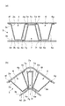
図1は、第1の実施形態に係る車体構造1の内部構造(一部外観を含む)を示した斜視図である。図1に示すように、車体構造1は、中空角柱状のロッカ(構造部材)2と、ロッカ2の内部空間3に設けられたバルクヘッド(補強部材)4及びバルクヘッド(補強部材)6と、内部空間3でバルクヘッド4とバルクヘッド6との間に設けられたバルクヘッド(荷重吸収部材)7とから構成される。
[First Embodiment]
FIG. 1 is a perspective view showing an internal structure (including a partial appearance) of a vehicle body structure 1 according to the first embodiment. As shown in FIG. 1, the vehicle body structure 1 includes a hollow prismatic rocker (structural member) 2, a bulkhead (reinforcing member) 4 and a bulkhead (reinforcing member) 6 provided in an
ロッカ2は、車両床面(図示せず)の左右両側に配置されるとともに車両前側から後側へ向かって延在するものであり、2つの断面略コ字型の部材を向かい合わせ溶接代にて溶接することによって形成されている。
The
ロッカ2の側面壁2aは車両内側に配置され、それに対して側面壁2aと対向する側面壁2bは車両外側に配置される。これによって、車両が側面衝突(側突)などを受けたときは、ロッカ2は、側面壁2b側から車両内側へ向かって変形する。また、側面壁2aの内壁面3aにバルクヘッド4とバルクヘッド6が固定され、側面壁2bの内壁面3bにバルクヘッド7が固定される。
The
バルクヘッド4は、鋼板を折り曲げることにより形成され、台形柱形状をなしている。このバルクヘッド4の矩形状の上面壁4aは、内壁面3aと水平に対向するとともに、ロッカ2の長手方向に沿って短縁部を有し、中空角柱2の高さ方向に沿って長縁部を有する。また、バルクヘッド4は、上面壁4aの短縁部から内壁面3aへ向かって広がりながら垂直に延びる台形側面壁4b及び台形側面壁4cと、上面壁4aの長縁部から内壁面3aへ向かって台形側面壁4b,4cの側縁部に沿って延びる傾斜側面壁4d及び傾斜側面壁4eと、傾斜側面壁4d,4eの内壁面3a側の縁部からバルクヘッド4の外側へ向かって張り出す溶接代4f及び溶接代4gと、を備えている。そして、溶接代4f,4gで内壁面3aに溶接されることによって固定される。
The
バルクヘッド6は、上述のバルクヘッド4と同様の形状の上面壁6a、台形側面壁6d,6c、傾斜側面壁6d,6e、溶接代6f,6gを有し、バルクヘッド4と傾斜側面壁4e側で隣接するように配置される。これによって、バルクヘッド6の傾斜側面壁6dの外側とバルクヘッド4の傾斜側面壁4eの外面とが、ロッカ2の長手方向に、所定の角度をなして対向することとなる。
The
なお、バルクヘッド4及びバルクヘッド6は、傾斜側面壁4eと傾斜側面壁6dとで、ロッカ2における曲げ座屈の生じ易い位置(例えばセンターピラーに対応する位置)を挟むように配置されている。
The
バルクヘッド7は、バルクヘッド4及びバルクヘッド6と同様の形状の上面壁7a、台形側面壁7b,7c、傾斜側面壁7d,7e、溶接代7f,7gを有しているが、バルクヘッド4,6よりも板厚が薄くされていることにより強度が弱くされている。また、バルクヘッド7はバルクヘッド4とバルクヘッド6に挟まれ向かい合うように配置されている。すなわち、バルクヘッド7は、その溶接代7f,7gで内壁面3bに溶接されることによって固定され、傾斜側面壁7eがバルクヘッド4の傾斜側面壁4eと対向し、傾斜側面壁7dがバルクヘッド6の傾斜側面壁6dと対向する。
The
次に、上述のように構成された車体構造1の作用・効果について、図2を用いて説明する。図2は、図1に示されたII−II線に沿った断面図であり、(a)に通常時の状態を示し、(b)に車両の側突などによってロッカ2に曲げ座屈が発生したときの状態を示す。
Next, operations and effects of the vehicle body structure 1 configured as described above will be described with reference to FIG. 2 is a cross-sectional view taken along the line II-II shown in FIG. 1. FIG. 2 (a) shows a normal state, and FIG. 2 (b) shows that the
図2(a)に示すように、通常時においては、バルクヘッド7は、バルクヘッド4及びバルクヘッド6のいずれとも接触していない。しかし、車両の側突などによりロッカ2に曲げ座屈変形が発生すると、図2(b)に示すように、バルクヘッド7が、バルクヘッド4の傾斜側面壁4e及びバルクヘッド6の傾斜側面壁6dに挟み込まれる。このため、傾斜側面壁4eと傾斜側面壁6dとの接近がバルクヘッド7によって抑制される。このとき、強度を弱くされたバルクヘッド7は、潰されながら衝突の際に生じる荷重のエネルギーを吸収する荷重吸収部材として作用する。これによって、ロッカ2は、バルクヘッド7に荷重を吸収されながら変形することとなる。従って、補強部材を過剰に用いることなく、ロッカ2の曲げ変形の進行を抑えることができる。
As shown in FIG. 2A, the
このとき、バルクヘッド4の傾斜側面壁4eの外面及びバルクヘッド6の傾斜側面壁6dの外面がなす角度を変えたり、傾斜側面壁4e及び傾斜側面壁6dの間の距離を変えることによってバルクヘッド7に与える荷重を変更し、ロッカ2の変形量(変形角度)を調整することができる。従って、ロッカ2の最適な変形量を得ることができる。
At this time, by changing the angle formed by the outer surface of the
更に、例えばバルクヘッド7を形成する鋼板の厚み、材質などを変えて、バルクヘッド7の強度を変えることにより荷重吸収特性を容易に調整することができ、これによってロッカ2の変形量及び変形速度を調整することができる。従って、この場合にも、ロッカ2の最適な変形量を得ることができる。
Furthermore, for example, the load absorption characteristic can be easily adjusted by changing the strength of the
[第2の実施形態]
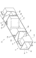
図3は、第2の実施形態に係る車体構造11の内部構造(一部外観を含む)を示した斜視図である。
[Second Embodiment]
FIG. 3 is a perspective view showing an internal structure (including a partial appearance) of the
図3において、車体構造11は、第1の実施形態と同様の構成を有するロッカ2と、ロッカ2の内部空間3に設けられたバルクヘッド14及びバルクヘッド16と、内部空間3でバルクヘッド14とバルクヘッド16との間に挟まれた弾性体17とから構成される。
In FIG. 3, the
バルクヘッド14は、鋼板を折り曲げることにより形成された断面コ字型部材からなる。このバルクヘッド14は、内壁面3aと垂直に配置された矩形状の側面壁14aと、当該側面壁14aの上下縁部からそれぞれバルクヘッド16の反対側へ向かって延びる側面壁14b及び側面壁14cと、を備えている。そして、側面壁14a〜14cの縁部で内壁面3aに溶接されることによって固定される。
The
バルクヘッド16は、上述のバルクヘッド14と同様の形状の側面壁16a〜16cを有し、側面壁16aがバルクヘッド14の側面壁14aと対向するように配置される。また、側面壁16bと側面壁16cとは、バルクヘッド14の反対側へ向かって延びる。
The
なお、バルクヘッド14及びバルクヘッド16は、側面壁14aと側面壁16aとで、ロッカ2における曲げ座屈の生じ易い位置を挟むように配置されている。
The
弾性体17は、例えばエポキシ樹脂等の荷重吸収特性を有する材質からなる。また、弾性体17は、略直方体形状からなり、長手方向の中央部に、内壁面3b側から内壁面3a側に向けて切り取られることにより形成される山形状の切り欠き部17aを有する。
The
上述のように構成された車体構造11では、車両の側突などによりロッカ2に曲げ座屈が発生すると、弾性体17が、バルクヘッド14の側面壁14a及びバルクヘッド16の側面壁16aに挟み込まれる。このとき、弾性体17が弾性変形しながら荷重を受け荷重吸収部材として作用する。これにより、ロッカ2の曲げ変形の進行を抑えることができる。更に、弾性体17の弾性特性を変えることにより荷重吸収特性を容易に調整することができ、これによってロッカ2の最適な変形量及び変形速度を得ることができる。
In the
なお、弾性体17の構造は、特に図3に示すものには限られない。例えば図4に示すように、切り欠き部17aの大きさ及び形状を変え、更に任意の位置に貫通穴17bを任意の数だけ設けることにより、弾性体17の強度を変えて、弾性体17の荷重吸収特性を変化させてもよい。
The structure of the
図5は、ロッカ2が曲げ座屈変形した場合における、変形開始からの経過時間Tと弾性体17にかかる変形荷重Fの関係を示した線図であり、実線は図3の車体構造11における特性を示し、点線は図4の車体構造11における特性を示している。図5に示すように、図3の車体構造11においては、変形直後は緩やかに変形荷重が増加し、時間が経過するにつれて変形荷重の増加が大きくなるのに対し、図4の車体構造11においては、変形直後は大きく変形荷重が増加し、それ以降は緩やかに変形荷重が増加する。
FIG. 5 is a diagram showing the relationship between the elapsed time T from the start of deformation and the deformation load F applied to the
以上のように、切り欠き部17aの大きさや形状を変えたり、貫通穴17bの数や大きさを変えることにより、弾性体17の荷重吸収特性を容易に調整することができる。これによって、用途に合わせて車体構造11の最適な変形量や、変形特性を得ることができる。
As described above, the load absorption characteristics of the
本発明は、上述した各実施形態に限定されるものではない。 The present invention is not limited to the above-described embodiments.
例えば、本実施形態ではバルクヘッドと荷重吸収部材との組み合わせをロッカ2の一箇所のみに形成しているが、複数箇所に形成してもよい。
For example, in this embodiment, the combination of the bulkhead and the load absorbing member is formed at only one location of the
また、本実施形態では、本発明の車体構造をロッカに適用しているが、それ以外の車体構造、例えばルーフレールやフロントサイドメンバ、バンパーリーンフォースメント等といった曲げ変形を受け易い部位に適用してもよい。 In this embodiment, the vehicle body structure of the present invention is applied to a rocker. However, the vehicle body structure is applied to other vehicle body structures such as roof rails, front side members, bumper reinforcements, and the like that are susceptible to bending deformation. Also good.
1,11…車体構造、2…ロッカ、3…内部空間、4,6,14,16…バルクヘッド(補強部材)、7…バルクヘッド(荷重吸収部材)、17…弾性体(荷重吸収部材)、17a…切り欠き部。
DESCRIPTION OF
Claims (4)
前記構造部材の前記内部空間に、前記構造部材の長手方向に並んで配置された少なくとも2つの補強部材と、
前記2つの補強部材の間に配置され、前記補強部材が受けた荷重を吸収する荷重吸収部材と、を備え、
前記補強部材は、前記荷重吸収部材に対向する側面をそれぞれ有し、前記構造部材に外力が作用して変形する際に前記補強部材の側面が前記荷重吸収部材と当接すると共に当該荷重吸収部材に対して圧力を付与するように配置されており、
前記荷重吸収部材は、一方の前記補強部材の側面と対向する側面、他方の前記補強部材の側面と対向する側面、及び前記荷重吸収部材の側面の2つを互いに連結する連結面を有しており、
前記構造部材に外力が作用して変形する際に、前記荷重吸収部材の側面の一方は、一方の前記補強部材の側面と当接し、前記荷重吸収部材の側面の他方は、他方の前記補強部材の側面と当接し、前記荷重吸収部材の連結面は、変形して衝撃吸収を行うように配置されていることを特徴とする車体構造。 A structural member having an internal space;
At least two reinforcing members arranged side by side in the longitudinal direction of the structural member in the internal space of the structural member;
A load absorbing member disposed between the two reinforcing members and absorbing the load received by the reinforcing member;
The reinforcing member has side surfaces facing the load absorbing member, and the side surface of the reinforcing member abuts on the load absorbing member when an external force acts on the structural member and deforms. Arranged to apply pressure against
The load absorbing member has a connecting surface that connects two of the side surface facing the side surface of the one reinforcing member, the side surface facing the side surface of the other reinforcing member, and the side surface of the load absorbing member. And
When the external force acts on the structural member and deforms, one of the side surfaces of the load absorbing member comes into contact with the side surface of the one reinforcing member, and the other side surface of the load absorbing member is the other reinforcing member. The vehicle body structure is characterized in that the connecting surface of the load absorbing member is disposed so as to be deformed and absorb the shock .
前記補強部材は、一方の前記部材に設けられており、 The reinforcing member is provided on one of the members,
前記荷重吸収部材は、他方の前記部材に設けられていることを特徴とする請求項1記載の車体構造。 The vehicle body structure according to claim 1, wherein the load absorbing member is provided on the other member.
一方の前記補強部材の側面と他方の前記補強部材の側面とは、互いにハ字状をなすように傾斜することを特徴とする請求項1又は3記載の車体構造。
One of the side surfaces of the load-absorbing member and the other side surface of the load-absorbing member are inclined so as to form a half-shape,
4. The vehicle body structure according to claim 1 , wherein a side surface of one of the reinforcing members and a side surface of the other reinforcing member are inclined so as to form a C shape.
Priority Applications (5)
| Application Number | Priority Date | Filing Date | Title |
|---|---|---|---|
| JP2006340458A JP4396699B2 (en) | 2006-12-18 | 2006-12-18 | Body structure |
| PCT/IB2007/004245 WO2008075200A1 (en) | 2006-12-18 | 2007-12-13 | Vehicle body structure |
| EP07859285A EP2094555B1 (en) | 2006-12-18 | 2007-12-13 | Hollow part of a car body with reinforcing element |
| CN2007800329892A CN101511663B (en) | 2006-12-18 | 2007-12-13 | Vehicle body structure |
| US12/446,510 US8066322B2 (en) | 2006-12-18 | 2007-12-13 | Vehicle body structure |
Applications Claiming Priority (1)
| Application Number | Priority Date | Filing Date | Title |
|---|---|---|---|
| JP2006340458A JP4396699B2 (en) | 2006-12-18 | 2006-12-18 | Body structure |
Publications (2)
| Publication Number | Publication Date |
|---|---|
| JP2008149914A JP2008149914A (en) | 2008-07-03 |
| JP4396699B2 true JP4396699B2 (en) | 2010-01-13 |
Family
ID=39296781
Family Applications (1)
| Application Number | Title | Priority Date | Filing Date |
|---|---|---|---|
| JP2006340458A Expired - Fee Related JP4396699B2 (en) | 2006-12-18 | 2006-12-18 | Body structure |
Country Status (5)
| Country | Link |
|---|---|
| US (1) | US8066322B2 (en) |
| EP (1) | EP2094555B1 (en) |
| JP (1) | JP4396699B2 (en) |
| CN (1) | CN101511663B (en) |
| WO (1) | WO2008075200A1 (en) |
Families Citing this family (19)
| Publication number | Priority date | Publication date | Assignee | Title |
|---|---|---|---|---|
| FR2943595B1 (en) * | 2009-03-26 | 2011-06-03 | Faurecia Bloc Avant | FRONT VEHICLE ASSEMBLY COMPRISING A FRONT BUMPER SHIELD |
| JP5564237B2 (en) * | 2009-11-27 | 2014-07-30 | 株式会社アステア | Bumper reinforcement |
| JP5516345B2 (en) * | 2010-11-11 | 2014-06-11 | マツダ株式会社 | Vehicle frame structure |
| US20120151843A1 (en) | 2010-12-20 | 2012-06-21 | Tesla Motors, Inc. | Vehicle Door Secondary Sealing System |
| US8757709B2 (en) | 2010-12-20 | 2014-06-24 | Tesla Motors, Inc. | Reinforced B-pillar assembly with reinforced rocker joint |
| US8702161B2 (en) * | 2010-12-22 | 2014-04-22 | Tesla Motors, Inc. | System for absorbing and distributing side impact energy utilizing an integrated battery pack and side sill assembly |
| US20120161472A1 (en) | 2010-12-22 | 2012-06-28 | Tesla Motors, Inc. | System for Absorbing and Distributing Side Impact Energy Utilizing an Integrated Battery Pack |
| US9290208B2 (en) * | 2011-12-07 | 2016-03-22 | Toyota Jidosha Kabushiki Kaisha | Vehicle body lower portion structure |
| US8608230B2 (en) * | 2012-04-13 | 2013-12-17 | Toyota Motor Engineering & Manufacturing North America, Inc. | Localized energy dissipation structures for vehicles |
| FR3009706B1 (en) | 2013-08-19 | 2016-10-21 | Peugeot Citroen Automobiles Sa | LONGERON OF A MOTOR VEHICLE. |
| US9211664B2 (en) | 2013-11-13 | 2015-12-15 | Honda Motor Co., Ltd. | Multi-piece acoustic spray foam control system and method |
| FR3016202B1 (en) | 2014-01-07 | 2016-05-13 | Autotech Eng A I E | METAL BEAM WITH FLEXION ANGLE LIMIT |
| DE102014107388A1 (en) * | 2014-05-26 | 2015-11-26 | Dr. Ing. H.C. F. Porsche Aktiengesellschaft | Underbody unit for a motor vehicle |
| CN104443061B (en) * | 2014-11-14 | 2018-01-23 | 浙江吉利汽车研究院有限公司 | Automobile door sill reinforcing structure and automobile |
| JP6215975B2 (en) * | 2016-01-12 | 2017-10-18 | 本田技研工業株式会社 | Battery fixing structure |
| US10906586B2 (en) * | 2016-08-02 | 2021-02-02 | Honda Motor Co., Ltd. | Vehicle body structure |
| CN110654466A (en) * | 2018-06-29 | 2020-01-07 | 重庆金康新能源汽车有限公司 | Vehicle body threshold beam, vehicle body and vehicle |
| DE102023005032A1 (en) | 2023-12-07 | 2024-08-22 | Mercedes-Benz Group AG | Side skirts for a car |
| DE102023005170A1 (en) | 2023-12-14 | 2024-08-29 | Mercedes-Benz Group AG | Side skirts for a car |
Family Cites Families (17)
| Publication number | Priority date | Publication date | Assignee | Title |
|---|---|---|---|---|
| JPH0542953Y2 (en) | 1988-01-22 | 1993-10-28 | ||
| JPH0630550Y2 (en) * | 1989-03-31 | 1994-08-17 | アイシン精機株式会社 | Vehicle bumper reinforcement |
| JPH0920267A (en) * | 1995-07-07 | 1997-01-21 | Hino Motors Ltd | Pillar structure of automobile |
| JPH10244970A (en) * | 1997-03-04 | 1998-09-14 | Nissan Motor Co Ltd | Sidesill structure of car body |
| US6003274A (en) * | 1998-02-13 | 1999-12-21 | Henkel Corporation | Lightweight laminate reinforcing web |
| US6247287B1 (en) * | 1998-08-05 | 2001-06-19 | Neo-Ex Lab, Inc. | Structure and method for closing and reinforcing hollow structural members |
| US6189953B1 (en) * | 1999-01-25 | 2001-02-20 | Henkel Corporation | Reinforced structural assembly |
| JP3381675B2 (en) | 1999-09-02 | 2003-03-04 | 日産自動車株式会社 | Body structure |
| US6321793B1 (en) * | 2000-06-12 | 2001-11-27 | L&L Products | Bladder system for reinforcing a portion of a longitudinal structure |
| US6471285B1 (en) | 2000-09-29 | 2002-10-29 | L&L Products, Inc. | Hydroform structural reinforcement system |
| BR0307185B1 (en) * | 2002-01-22 | 2013-04-30 | Method for reinforcing a vehicle structural body and reinforced vehicle structural body. | |
| JP3951742B2 (en) * | 2002-02-27 | 2007-08-01 | トヨタ自動車株式会社 | Body structure |
| DE10240196A1 (en) * | 2002-08-28 | 2004-03-11 | Henkel Kgaa | Separation element suitable for mechanical fixing in hollow spaces of structural members has a peripheral rim with a high coefficient of friction, and an opening within its inner zone |
| JP4207806B2 (en) * | 2004-03-02 | 2009-01-14 | 日産自動車株式会社 | Body floor structure |
| JP4587782B2 (en) * | 2004-11-08 | 2010-11-24 | 株式会社アステア | Bulkhead member |
| JP4420830B2 (en) * | 2005-01-24 | 2010-02-24 | 本田技研工業株式会社 | Shock absorbing member |
| GB0600901D0 (en) | 2006-01-17 | 2006-02-22 | L & L Products Inc | Improvements in or relating to reinforcement of hollow profiles |
-
2006
- 2006-12-18 JP JP2006340458A patent/JP4396699B2/en not_active Expired - Fee Related
-
2007
- 2007-12-13 WO PCT/IB2007/004245 patent/WO2008075200A1/en active Application Filing
- 2007-12-13 US US12/446,510 patent/US8066322B2/en not_active Expired - Fee Related
- 2007-12-13 CN CN2007800329892A patent/CN101511663B/en not_active Expired - Fee Related
- 2007-12-13 EP EP07859285A patent/EP2094555B1/en not_active Not-in-force
Also Published As
| Publication number | Publication date |
|---|---|
| EP2094555B1 (en) | 2012-11-14 |
| US20100314905A1 (en) | 2010-12-16 |
| WO2008075200A1 (en) | 2008-06-26 |
| JP2008149914A (en) | 2008-07-03 |
| CN101511663A (en) | 2009-08-19 |
| US8066322B2 (en) | 2011-11-29 |
| CN101511663B (en) | 2010-12-08 |
| EP2094555A1 (en) | 2009-09-02 |
Similar Documents
| Publication | Publication Date | Title |
|---|---|---|
| JP4396699B2 (en) | Body structure | |
| KR20210107682A (en) | Vehicle locker structure and method for obtaining the same | |
| JP5549964B2 (en) | Frame structure for vehicles with excellent collision resistance | |
| KR102307638B1 (en) | shock absorbing member | |
| JP5353209B2 (en) | Shock absorbing member | |
| JP6913029B2 (en) | Energy absorbing member | |
| JP5130878B2 (en) | Shock absorbing structure | |
| JP5125928B2 (en) | Body structure | |
| JP2005145224A (en) | Hood structure for vehicle | |
| JP5207228B2 (en) | Inner panel for vehicle | |
| JP6681912B2 (en) | Motor vehicle lockers and vehicles equipped with such rockers | |
| JP3949138B2 (en) | End wall module | |
| JP2023534786A (en) | Metal structural component with highly ductile patch and method of making same | |
| EP4035974A1 (en) | Side sill for vehicle | |
| JP5056545B2 (en) | Bumper mounting structure for vehicles | |
| JP2006502047A5 (en) | ||
| JP6035654B2 (en) | Auto body structure | |
| JP5234324B2 (en) | Vehicle body structure | |
| JP7088085B2 (en) | Vehicle load absorbing member | |
| JP5617681B2 (en) | Bumper for vehicle | |
| JP5333352B2 (en) | Vehicle end structure | |
| JP7060560B2 (en) | Body front structure | |
| JP2005271734A (en) | Shock absorbing structure of vehicle front part | |
| JP4979502B2 (en) | Body superstructure | |
| JP2005075255A (en) | Shock absorbing structural body for railway vehicle |
Legal Events
| Date | Code | Title | Description |
|---|---|---|---|
| A977 | Report on retrieval |
Free format text: JAPANESE INTERMEDIATE CODE: A971007 Effective date: 20081110 |
|
| A131 | Notification of reasons for refusal |
Free format text: JAPANESE INTERMEDIATE CODE: A131 Effective date: 20081125 |
|
| A521 | Request for written amendment filed |
Free format text: JAPANESE INTERMEDIATE CODE: A523 Effective date: 20090122 |
|
| A131 | Notification of reasons for refusal |
Free format text: JAPANESE INTERMEDIATE CODE: A131 Effective date: 20090303 |
|
| A521 | Request for written amendment filed |
Free format text: JAPANESE INTERMEDIATE CODE: A523 Effective date: 20090428 |
|
| A131 | Notification of reasons for refusal |
Free format text: JAPANESE INTERMEDIATE CODE: A131 Effective date: 20090630 |
|
| A521 | Request for written amendment filed |
Free format text: JAPANESE INTERMEDIATE CODE: A523 Effective date: 20090831 |
|
| TRDD | Decision of grant or rejection written | ||
| A01 | Written decision to grant a patent or to grant a registration (utility model) |
Free format text: JAPANESE INTERMEDIATE CODE: A01 Effective date: 20090929 |
|
| A01 | Written decision to grant a patent or to grant a registration (utility model) |
Free format text: JAPANESE INTERMEDIATE CODE: A01 |
|
| A61 | First payment of annual fees (during grant procedure) |
Free format text: JAPANESE INTERMEDIATE CODE: A61 Effective date: 20091012 |
|
| FPAY | Renewal fee payment (event date is renewal date of database) |
Free format text: PAYMENT UNTIL: 20121030 Year of fee payment: 3 |
|
| R151 | Written notification of patent or utility model registration |
Ref document number: 4396699 Country of ref document: JP Free format text: JAPANESE INTERMEDIATE CODE: R151 |
|
| FPAY | Renewal fee payment (event date is renewal date of database) |
Free format text: PAYMENT UNTIL: 20121030 Year of fee payment: 3 |
|
| FPAY | Renewal fee payment (event date is renewal date of database) |
Free format text: PAYMENT UNTIL: 20131030 Year of fee payment: 4 |
|
| LAPS | Cancellation because of no payment of annual fees |