JP4396014B2 - Air conditioner - Google Patents
Air conditioner Download PDFInfo
- Publication number
- JP4396014B2 JP4396014B2 JP2000282258A JP2000282258A JP4396014B2 JP 4396014 B2 JP4396014 B2 JP 4396014B2 JP 2000282258 A JP2000282258 A JP 2000282258A JP 2000282258 A JP2000282258 A JP 2000282258A JP 4396014 B2 JP4396014 B2 JP 4396014B2
- Authority
- JP
- Japan
- Prior art keywords
- air
- flow
- mixing chamber
- air flow
- wall
- Prior art date
- Legal status (The legal status is an assumption and is not a legal conclusion. Google has not performed a legal analysis and makes no representation as to the accuracy of the status listed.)
- Expired - Fee Related
Links
Images


Classifications
-
- F—MECHANICAL ENGINEERING; LIGHTING; HEATING; WEAPONS; BLASTING
- F24—HEATING; RANGES; VENTILATING
- F24F—AIR-CONDITIONING; AIR-HUMIDIFICATION; VENTILATION; USE OF AIR CURRENTS FOR SCREENING
- F24F13/00—Details common to, or for air-conditioning, air-humidification, ventilation or use of air currents for screening
- F24F13/02—Ducting arrangements
- F24F13/04—Air-mixing units
-
- B—PERFORMING OPERATIONS; TRANSPORTING
- B01—PHYSICAL OR CHEMICAL PROCESSES OR APPARATUS IN GENERAL
- B01F—MIXING, e.g. DISSOLVING, EMULSIFYING OR DISPERSING
- B01F25/00—Flow mixers; Mixers for falling materials, e.g. solid particles
- B01F25/40—Static mixers
- B01F25/42—Static mixers in which the mixing is affected by moving the components jointly in changing directions, e.g. in tubes provided with baffles or obstructions
- B01F25/43—Mixing tubes, e.g. wherein the material is moved in a radial or partly reversed direction
- B01F25/432—Mixing tubes, e.g. wherein the material is moved in a radial or partly reversed direction with means for dividing the material flow into separate sub-flows and for repositioning and recombining these sub-flows; Cross-mixing, e.g. conducting the outer layer of the material nearer to the axis of the tube or vice-versa
- B01F25/4321—Mixing tubes, e.g. wherein the material is moved in a radial or partly reversed direction with means for dividing the material flow into separate sub-flows and for repositioning and recombining these sub-flows; Cross-mixing, e.g. conducting the outer layer of the material nearer to the axis of the tube or vice-versa the subflows consisting of at least two flat layers which are recombined, e.g. using means having restriction or expansion zones
-
- B—PERFORMING OPERATIONS; TRANSPORTING
- B60—VEHICLES IN GENERAL
- B60H—ARRANGEMENTS OF HEATING, COOLING, VENTILATING OR OTHER AIR-TREATING DEVICES SPECIALLY ADAPTED FOR PASSENGER OR GOODS SPACES OF VEHICLES
- B60H1/00—Heating, cooling or ventilating [HVAC] devices
- B60H1/00007—Combined heating, ventilating, or cooling devices
- B60H1/00021—Air flow details of HVAC devices
- B60H1/00064—Air flow details of HVAC devices for sending air streams of different temperatures into the passenger compartment
-
- B—PERFORMING OPERATIONS; TRANSPORTING
- B01—PHYSICAL OR CHEMICAL PROCESSES OR APPARATUS IN GENERAL
- B01F—MIXING, e.g. DISSOLVING, EMULSIFYING OR DISPERSING
- B01F23/00—Mixing according to the phases to be mixed, e.g. dispersing or emulsifying
- B01F23/10—Mixing gases with gases
-
- B—PERFORMING OPERATIONS; TRANSPORTING
- B01—PHYSICAL OR CHEMICAL PROCESSES OR APPARATUS IN GENERAL
- B01F—MIXING, e.g. DISSOLVING, EMULSIFYING OR DISPERSING
- B01F35/00—Accessories for mixers; Auxiliary operations or auxiliary devices; Parts or details of general application
- B01F35/90—Heating or cooling systems
-
- B—PERFORMING OPERATIONS; TRANSPORTING
- B60—VEHICLES IN GENERAL
- B60H—ARRANGEMENTS OF HEATING, COOLING, VENTILATING OR OTHER AIR-TREATING DEVICES SPECIALLY ADAPTED FOR PASSENGER OR GOODS SPACES OF VEHICLES
- B60H1/00—Heating, cooling or ventilating [HVAC] devices
- B60H1/00007—Combined heating, ventilating, or cooling devices
- B60H1/00021—Air flow details of HVAC devices
- B60H2001/00078—Assembling, manufacturing or layout details
- B60H2001/00092—Assembling, manufacturing or layout details of air deflecting or air directing means inside the device
Description
【0001】
【発明の属する技術分野】
本発明は、温度が相違する第1空気流と第2空気流とを混合させることにより室内に吹き出す空気の温度を調節するエアミックス式の空調装置に関するもので、車両用空調装置に適用して有効である。
【0002】
【従来の技術】
エアミックス式の空調装置として、例えば特開平4−95520号公報に記載の発明では、暖風が流れる空気層(暖風層)と冷風が流れる空気層(冷風層)とがエアミックスチャンバ(空気混合室)から見て交互に発生させることにより暖風と冷風とを良好に混合している。
【0003】
【発明が解決しようとする課題】
ところで、発明者等は、上記公報に記載の発明について詳細検討を行ったところ、空気混合室(空調ケーシング)の容積(特に、空気の流通方向と平行な部位の長さ)が小さい場合には、十分に暖風と冷風とを混合することができないということを発見した。
【0004】
本発明は、上記点に鑑み、空気混合室(空調ケーシング)の容積(特に、空気の流通方向と平行な部位の長さ)が小さい場合であっても、十分に暖風と冷風とを混合することを目的とする。
【0005】
【課題を解決するための手段】
本発明は、上記目的を達成するために、請求項1に記載の発明では、温度が相違する第1空気流と第2空気流とを混合させることにより室内に吹き出す空気の温度を調節するエアミックス式の空調装置であって、第1空気流が導入される第1導入口(101)、第1導入口(101)と交差する方向に開口して第2空気流が導入される第2導入口(102)、並びに第1導入口(101)から導入された第1空気流及び第2導入口(102)から導入された第2空気流が流出する流出口(103)を有する空気混合室(10)と、第1、2導入口(101、102)を複数に仕切るとともに、空気の流れと平行な方向に延びる案内壁(104、105)とを有し、空気混合室(10)は、第1、2空気流のうち少なくとも一方の空気流が空気混合室(10)の内壁に衝突して、その流通方向を転向させた後、流出口(103)側に流れるように構成され、案内壁(104、105)は、流出口(103)側から見て、第1空気流の空気層と第2空気流の空気層とが交互に発生するように設けられており、さらに、案内壁(104、105)のうち空気混合室(10)の内壁に衝突する衝突空気流を案内する案内壁(104)の案内長さ(a1)は、両導入口(101、102)のうち衝突空気流が導入される導入口(101)から衝突空気流が衝突する空気混合室(10)の内壁までの寸法(L1)の0.05倍以上、0.5倍以下であることを特徴とする。
【0006】
ところで、流出口(103)側から見て、冷風層と暖風層とが交互に発生するように案内壁(104、105)を設けているのは、第1空気流と第2空気流との接触面積を増大させて両空気流のエアミックスス性を向上させるためである。
【0007】
したがって、エアミックス性を確実に向上させるには、確実に2種類の空気層を形成した状態で第1、2空気流を空気混合室(10)内にに進入させる必要がある。
【0008】
ここで、案内壁(104、105)の案内長さ(a1、a2)が小さいと、空気層が形成されないまま第1、2空気流が空気混合室(10)内に進入してしまい、エアミックス性を向上させることができない。
【0009】
逆に、案内壁(104、105)の案内長さ(a1、a2)が過度に大きいと、空気混合室(10)のうち空気を混合させる空間の容積(特に、空気の流通方向と平行な部位の長さ)が小さくなるので、第1、2空気流を十分に混合することができない。
【0010】
これに対して、衝突空気流側を案内する案内壁(104)の案内長さ(a1)を本発明のように設定すれば、後述するように、エアミックス性を向上させることができる。
【0011】
そして、空気混合室(10)が、第1、2空気流のうち一方の空気流が空気混合室(10)の内壁に衝突して、その流通方向を転向させた後、流出口(103)側に流れるとともに、第1、2空気流のうち他方の空気流が空気混合室(10)の内壁に衝突しないで流出口(103)側に流れるように構成されている場合、さらに、請求項2に記載の発明のごとく、案内壁(104、105)のうち空気混合室(10)の内壁に衝突しないで流出口(103)側に流れる非衝突空気流を案内する案内壁(105)の案内長さ(a2)を、衝突空気流を案内する案内壁(104)のうち非衝突空気流の流通方向と平行な部位の寸法(L2)の0.05倍以上、0.5倍以下とすれば、さらにエアミックス性を向上させることができる。
【0012】
ところで、衝突空気流の速度が大きいと、後述するように、温度バラツキが大きくなるが、請求項3に記載の発明のごとく、衝突空気流を案内する導入口(104)は、衝突空気流の流速が所定流速以下となるように仕切れば、温度バラツキを小さくすることができる。
【0013】
また、請求項4に記載の発明のごとく、両導入口(104、105)のうち少なくとも一方には、空気流を減速させる減速手段(108)を設ければ、さらに温度バラツキを小さくすることができる。
【0014】
請求項5に記載の発明では、第1空気流と第1導入口(101)との交差角度(θ)を80°以上、170°以下としたことを特徴とする。
【0015】
これにより、エアミックス性を向上させることができる。
【0016】
請求項6に記載の発明では、流出口(103)から流出する流出空気の主流方向と、第1空気流又は第2空気流の主流方向との交差角度(γ)を−40°以上、40以下としたことを特徴とする。
【0017】
これにより、エアミックス性を向上させることができる。
【0018】
なお、第1空気流の温度は第2空気流の温度より低く、かつ、室内下方側に空気を吹き出すときには、請求項7に記載の発明のごとく、流出空気の主流方向と第2空気流の主流方向との交差角度が、流出空気の主流方向と第1空気流の主流方向との交差角度より小さくなるように構成することが望ましい。
【0019】
また、第1空気流の温度は第2空気流の温度より低く、かつ、室内上方側に空気を吹き出すときには、請求項8に記載の発明のごとく、流出空気の主流方向と第1空気流の主流方向との交差角度が、流出空気の主流方向と第2空気流の主流方向との交差角度より小さくなるように構成することが望ましい。
【0020】
因みに、上記各手段の括弧内の符号は、後述する実施形態に記載の具体的手段との対応関係を示す一例である。
【0021】
【発明の実施の形態】
(第1実施形態)
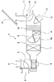
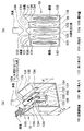
本実施形態は、本発明に係る空調装置を車両用空調装置に適用したものであって、図1は車両用空調装置(以下、空調装置と略す。)1の模式図である。
【0022】
2は車室内に吹き出す空気が流通する空調ケーシング(空調ダクト)であり、この空調ケーシング2の空気上流側部位には、車室内気を吸入するための内気吸入口3と外気を吸入するための外気吸入口4とが形成されているとともに、これらの吸入口3、4を選択的に開閉する吸入口切換ドア5が設けられている。なお、この吸入口切換ドア5は、サーボモータ等の駆動手段または手動操作によって開閉される。
【0023】
また、吸入口切換ドア5の下流側部位には、遠心式の送風機6が配設されており、この送風機6により両吸入口3、4から吸入された空気が、後述する各吹出口11、12、13に向けて送風されている。また、送風機6の空気下流側には、空気冷却手段をなす蒸発器7が配設されており、送風機6により送風された空気は全てこの蒸発器7を通過する。
【0024】
そして、蒸発器7の空気下流側には、空気加熱手段をなすヒータコア8が配設されており、このヒータコア8は、走行用エンジン(図示せず。)の冷却水を熱源として空気を加熱している。
【0025】
また、空調ケーシング2には、ヒータコア8を迂回するバイパス通路9が形成されており、ヒータコア8の空気上流側には、ヒータコア8を通過する風量とバイパス通路9を通過する風量との風量割合を調節するエアミックスドア9aが配設されている。なお、以下、ヒータコア8を通過して加熱された空気を暖風と呼び、バイパス通路9を通過した空気を冷風と呼ぶ。
【0026】
そして、ヒータコア8及びバイパス通路9の下流側には、暖風が流れる複数の空気層(暖風層)と冷風が流れる複数の空気層(冷風層)とを形成して、暖風と冷風とを混合する空気混合室(エアミックスチャンバ)10が設けられている。なお、空気混合室10の詳細は後述する。
【0027】
また、空調ケーシング2の最下流側部位には、車室内乗員の上半身に空調空気を吹き出すためのフェイス吹出口11と、車室内乗員の足元に空気を吹き出すためのフット吹出口12と、フロントガラス14の内面に向かって空気を吹き出すためのデフロスタ吹出口13とが形成されている。
【0028】
そして、上記各吹出口11〜13の空気上流側部位には、それぞれ吹出モード切換ドア15、16が配設されている。なお、これらの吹出モード切換ドア15、16は、サーボモータ等の駆動手段または手動操作によって開閉される。
【0029】
次に、空気混合室10について述べる。
【0030】
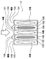
図2の斜線部分が空気混合室(以下、混合室と略す。)10を示しており、図図3(a)に示すように、暖風は水平方向から混合室10に流入し、冷風は上方側から下方側に向かうようにして混合室10に流入する。
【0031】
このため、混合室10の上方側に冷風(第1空気流)が導入される第1導入口101が設けられ、第1導入口101と直交する方向に開口するように暖風(第2空気流)が導入される第2導入口102が設けられている。
【0032】
また、略正六面体の混合室10のうち第2導入口102の反対側には、両道入口101、102から導入された冷風及び暖風が流出する流出口103が設けられている。
【0033】
このため、第1導入口101から混合室10内に導入された冷風は、混合室10の下方側の内壁に衝突して、その流通方向を約90°転向して流出口103から各吹出口11〜13側に向けて流通し、暖風は混合室10の内壁に衝突することなく、その流通方向を変えないで真っ直ぐに各吹出口11〜13側に向けて流通する。
【0034】
なお、本明細書で言う「空気(冷風又は暖風)が混合室10の内壁に衝突する」又は「空気(冷風又は暖風)が混合室10の内壁に衝突しない」とは、厳密な意味ではなく、空気流れを巨視的に見て「衝突する」又は「衝突しない」という意味である。
【0035】
そして、両導入口101、102には、各導入口101、102から空気流れと平行に混合室10の内側に延出するとともに、両導入口101、102を複数個に仕切る案内壁104、105が形成されており、これら案内壁104、105は、流出口103側から見て、図3(b)に示すように冷風の空気層(以下、冷風層と呼ぶ。)と暖風の空気層(以下、暖風層と呼ぶ。)とが交互に発生するように設けられている。
【0036】
以下、冷風を案内して冷風層を形成する案内壁104を第1案内壁104と呼び、暖風を案内して暖風層を形成する案内壁105を第2案内壁105と呼び、混合室10のうち第1、2案内壁104、105が存在しない空間107を混合空間107と呼ぶ。そして、第1、2案内壁104、105により空気を層にして衝突させる多層構造部が構成されている。
【0037】
因みに、第1、2案内壁104、105のうち空気流れ上流側には、各空気層に空気を滑らかに導くべく、空気流れ上流側に向かうほど、断面積が小さくなるテーパ部106が設けられている。
【0038】
次に、本実施形態の特徴を述べる。
【0039】
ところで、流出口103側から見て、冷風層と暖風層とが交互に発生するように第1、2案内壁104、105を設けているのは、冷風と暖風との接触面積を増大させて冷風と暖風とのエアミックスス性を向上させるためである。したがって、エアミックス性を確実に向上させるには、確実に冷風層と暖風層とを形成した状態で冷風と暖風とを混合空間107内に進入させる必要がある。
【0040】
ここで、第1、2案内壁104、105の案内長さa1、a2が小さいと、冷風層及び暖風層が形成されないまま冷風と暖風とが混合空間107に進入してしまい、エアミックス性を向上させることができない。
【0041】
逆に、第1、2案内壁104、105の案内長さa1、a2が過度に大きいと、混合空間107の容積(特に、空気の流通方向と平行な部位の長さ)が小さくなるので、冷風と暖風とを十分に混合することができない。
【0042】
なお、第1、2案内壁104、105の案内長さa1、a2とは、案内壁104、105のうち案内する空気の流通方向と平行な部位の寸法を言うものである。
【0043】
そこで、発明者等は、冷風は混合室10の内壁に衝突して、その流通方向を略90°転向させることから、第1導入口101から冷風(衝突空気流)が衝突する混合室10の内壁までの寸法L1(図3(a)参照)と第1案内長さa1との関係を数値シミレーションにより検討したところ、図4に示すように、第1案内長さa1を寸法L1の0.05倍以上、0.5倍以下とすることが望ましいとの結論を得た。
【0044】
また、空気混合室10の内壁に衝突しないで流出口103側に流れる暖風(非衝突空気流)を案内する第2案内壁105の案内長さa2は、冷風を案内する第1案内壁104のうち暖風の流通方向と平行な部位の寸法L2(図3(a)参照)の0.05倍以上、0.5倍以下とすることが望ましいとの結論を得た。
【0045】
したがって、第1案内長さa1を寸法L1の0.05倍以上、0.5倍以下とし、かつ、案内長さa2を寸法L2の0.05倍以上、0.5倍以下とすれば、図5に示すように、冷風と暖風とを十分に混合して温度バラツキを小さくすることができる。
【0046】
なお、本実施形態では、第1案内長さa1を寸法L1の0.05倍以上、0.5倍以下とし、かつ、案内長さa2を寸法L2の0.05倍以上、0.5倍以下としたが、少なくとも第1案内長さa1を寸法L1の0.05倍以上、0.5倍以下とすれば、実用上問題がない。
【0047】
(第2実施形態)
ところで、冷風量が増大すると、混合室10の内壁に衝突した冷風が暖風を押し上げるようにその流通の向きを転向するので、冷風の風速が大きくなると、冷風と暖風とを十分に混合することができなくなる。
【0048】
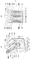
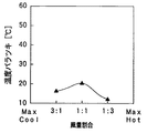
そこで、本実施形態では、図6に示すように、複数本の暖風層のうち第1導入口101の略中央部に位置する暖風層に冷風を流通させることにより、1本の冷風層当たりの風量を減らし、複数本の冷風層における冷風の風速を所定流速以下となるように減速している。
【0049】
これにより、混合室10の内壁に衝突した冷風が暖風を押し上げることを抑制できるので、図7に示すように、冷風と暖風とを十分に混合して温度バラツキを小さくすることができる。
【0050】
なお、本実施形態では、暖風層の一部に冷風を流通させることにより、各冷風層の流速を低下させたが、冷風層の幅寸法Wを大きくする又は冷風層の本数を増大させる等して冷風層の総通路断面積を大きくしてもよい。
【0051】
また、本実施形態では、複数本の暖風層のうち第1導入口101の略中央部に位置する暖風層に冷風を流通させたが、これは、第1導入口101の略中央部が最も風速分布が大きくなるからであり、冷風を流通させる暖風層は第1導入口101の略中央部に限定されるものではない。
【0052】
(第3実施形態)
本実施形態は、暖風層に冷風を流通させるとともに、図8に示すように、冷風を減速させる(暖風層に冷風が多量に流入することを防止する)キャップ108(減速手段)を設けたものである。
【0053】
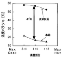
これにより、混合空間107に流入する冷風の風速分布を均一化しつつ、混合室10の内壁に衝突した冷風が暖風を押し上げることを抑制できる。したがって、図9の実線に示すように、冷風と暖風とを十分に混合して温度バラツキを小さくすることができる。
【0054】
なお、本実施形態では、キャップ108は第1案内壁104に固定されていたが、エアミックスドア9aの開度や吹出モード切換ドア15、16の状態によっては風速分布が最も大きくなる位置が変動するので、エアミックスドア9aの開度や吹出モード切換ドア15、16の作動に連動させてキャップ108の位置を可変制御してもよい。
【0055】
なお、図9の破線はエアミックスドア9aの開度に連動させてキャップ108の位置を可変制御したときの温度バラツキを示すものである。
【0056】
因みに、図6、7、9に示す温度バラツキのグラフは、混合室10から50mm離れた点における試験結果である。
【0057】
(第4実施形態)
本実施形態は、図10に示すように、冷風層と暖風層との並びを第1〜3実施形態に対して逆にしたものである。
【0058】
(第5実施形態)
上述の実施形態では、冷風は混合室10の下方側の内壁に衝突してその流通方向を約90°転向して流出口103から各吹出口11〜13側に向けて流通し、暖風は混合室10の内壁に衝突することなく真っ直ぐに各吹出口11〜13側に向けて流通するものであったが、本実施形態は、図11に示すように、冷風及び暖風の両者が混合室10の内壁に衝突して、その流通方向が転向するものである。
【0059】
なお、本実施形態では、導入口101、102から空気流が衝突する内壁までの寸法Lは、空気が流入する部位によって相違するので、案内長さa1、a2は寸法Lの平均値を基に決定している。
【0060】
なお、案内長さa1、a2を寸法Lの変化(空気が流入する部位)に応じて変えてもよい。
【0061】
(第6実施形態)
上述の実施形態では、冷風と暖風との衝突角度θが任意であったが、本実施形態は、冷風と暖風との衝突角度θを80°以上、170°以下としたものである。
【0062】
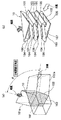
ここで、衝突角度θとは、図12、13に示すように、空気混合室10に進入する冷風の主流方向(白抜きの矢印方向)と空気混合室10に進入する暖風の主流方向(斜線の矢印方向)とのなす角を言い、具体的には、第1導入口101に連なる第1ダクト部101aの軸方向と第2導入口に連なる第2ダクト部102aの軸方向とのなす角をもって衝突角度θとしている。
【0063】
そして、図14は衝突角度θと衝突後空気の温度バラツキとの関係を示す数値シミレーション結果であり、図14から明らかなように衝突角度θを80°以上、170°以下とすれば、衝突後空気の温度バラツキを小さくすることができる。
【0064】
因みに、図15は冷風と暖風との衝突状態を示す模式図であり、衝突角度θが80°以上、170°以下の場合(図15(a)参照)には、冷風と暖風とが適度に混合するように冷風と暖風とが適度に衝突し、衝突角度θが80°未満の場合(図15(b)参照)には、冷風と暖風とが十分に混合することなく空気混合室10から流出してしまい、衝突角度θが170°より大きい場合(図15(c)参照)には、冷風と暖風とが噴流となって衝突するため冷風と暖風とを十分に混合することが難しい。
【0065】
(第7実施形態)
本実施形態は、衝突後空気の主流方向と、空気混合室10に流入する冷風又は暖風の主流方向との交差角度(以下、この角度を吹出角度γと呼ぶ。)が−40°以上、40以下となるように構成したものである。なお、交差角度は、絶対値で小さい方の角度を採用する。
【0066】
ここで、衝突後空気の主流方向とは、図16、17に示すように、流出口103に連なるダクト部103の軸方向を言いう。
【0067】
また、空気混合室10に流入する冷風との交差角度で吹出角度γを規定した場合においては、冷風の主流方向を基準(0°)として暖風の主流方向側を正(+)とし、反対側を負(−)とする。一方、空気混合室10に流入する暖風との交差角度で吹出角度γを規定した場合においては、暖風の主流方向を基準(0°)として冷風の主流方向側を正(+)とし、反対側を負(−)とする。
【0068】
そして、図18は吹出角度γと衝突後空気の温度バラツキとの関係を示す数値シミレーション結果であり、図18から明らかなように吹出角度γを−40°以上、40以下とすれば、衝突後空気の温度バラツキを小さくすることができる。
【0069】
因みに、図19は冷風と暖風との衝突状態を示す模式図であり、吹出角度γを−40°以上、40以下の場合には、冷風と暖風とが適度に混合するように冷風と暖風とが適度に衝突する。
【0070】
したがって、フット吹出口12のごとく、比較的温度の高い空気を車室内下方側に空気を吹き出す場合には、図20のA部に示すように、衝突後空気の主流方向と暖風の主流方向との交差角度が、衝突後空気の主流方向と冷風の主流方向との交差角度より小さくなるように空調ケーシング2(空気混合室10)を構成し、一方、フェイス吹出口11やデフロスタ吹出口13のごとく、比較的温度の低い空気を車室内上方側に空気を吹き出す場合には、図21のA部に示すように、衝突後空気の主流方向と冷風の主流方向との交差角度が、衝突後空気の主流方向と暖風の主流方向との交差角度より小さくなるように空調ケーシング2(空気混合室10)を構成することが望ましい。
【0071】
具体的には、フット吹出口12のごとく、比較的温度の高い空気を車室内下方側に空気を吹き出す部位においては、暖風が略直線的に流通するように構成し、フェイス吹出口11やデフロスタ吹出口13のごとく、比較的温度の低い空気を車室内上方側に空気を吹き出す部位においては、冷風が略直線的に流通するように構成することが望ましい。
【0072】
(その他の実施形態)
第1〜4実施形態では、冷風は混合室10の下方側の内壁に衝突してその流通方向を約90°転向して流出口103から各吹出口11〜13側に向けて流通し、暖風は混合室10の内壁に衝突することなく真っ直ぐに各吹出口11〜13側に向けて流通させたが、本発明はこれに限定されるものではなく、冷風及び暖風を第1〜4実施形態と逆向きに流通させてもよい。
【0073】
また、第1〜4実施形態では、第1導入口101と第2導入口102とは直交していたが、本発明はこれに限定されるものではない。
【図面の簡単な説明】
【図1】本発明の第1実施形態に係る空調装置の模式図である。
【図2】本発明の第1実施形態に係る空気混合室の模式図である。
【図3】(a)は本発明の第1実施形態に係る空気混合室の斜視図であり、(b)は流出口から見た本発明の第1実施形態に係る空気混合室の模式図である。
【図4】本発明の第1実施形態に係る空気混合室を用いた場合の温度バラツキと寸法比との関係を示すグラフである。
【図5】本発明の第1実施形態に係る空気混合室を用いた場合の温度バラツキと風量割合との関係を示すグラフである。
【図6】(a)は本発明の第2実施形態に係る空気混合室の斜視図であり、(b)は流出口から見た本発明の第2実施形態に係る空気混合室の模式図である。
【図7】本発明の第2実施形態に係る空気混合室を用いた場合の温度バラツキと風量割合との関係を示すグラフである。
【図8】(a)は本発明の第3実施形態に係る空気混合室の斜視図であり、(b)は流出口から見た本発明の第3実施形態に係る空気混合室の模式図である。
【図9】本発明の第3実施形態に係る空気混合室を用いた場合の温度バラツキと風量割合との関係を示すグラフである。
【図10】本発明の第4実施形態に係る空気混合室を流出口から見た場合の模式図である。
【図11】(a)は本発明の第5実施形態に係る空気混合室の模式図であり、(b)は本発明の第5実施形態に係る空気混合室の模式図である。
【図12】(a)は本発明の第6実施形態に係る空気混合室の模式図であり、(b)は本発明の第5実施形態に係る空気混合室の模式図である。
【図13】(a)は本発明の第6実施形態に係る空気混合室の模式図であり、(b)は本発明の第5実施形態に係る空気混合室の模式図である。
【図14】本発明の第6実施形態に係る空気混合室を用いた場合の衝突角度θと衝突後空気の温度バラツキとの関係を示すグラフである。
【図15】空気混合室内における空気流れを示す模式図である。
【図16】(a)は本発明の第7施形態に係る空気混合室の模式図であり、(b)は本発明の第7実施形態に係る空気混合室の斜視図であり、(c)は流出口から見た本発明の第7実施形態に係る空気混合室の模式図である。
【図17】(a)は本発明の第7施形態に係る空気混合室の模式図であり、(b)は本発明の第7実施形態に係る空気混合室の斜視図であり、(c)は流出口から見た本発明の第7実施形態に係る空気混合室の模式図である。
【図18】本発明の第7実施形態に係る空気混合室を用いた場合の吹出角度γと衝突後空気の温度バラツキとの関係を示すグラフである。
【図19】空気混合室内における空気流れを示す模式図である。
【図20】本発明の第7実施形態に係る空気混合室を用いた空調ケーシングの模式図である。
【図21】本発明の第7実施形態に係る空気混合室を用いた空調ケーシングの模式図である。
【符号の説明】
10…空気混合室、101…第1導入口、102…第2導入口、
103…流出口、104、105…案内壁。[0001]
BACKGROUND OF THE INVENTION
The present invention relates to an air mix type air conditioner that adjusts the temperature of air blown into a room by mixing a first air flow and a second air flow having different temperatures, and is applied to a vehicle air conditioner. It is valid.
[0002]
[Prior art]
As an air mix type air conditioner, for example, in the invention described in Japanese Patent Application Laid-Open No. 4-95520, an air layer (warm air layer) through which warm air flows and an air layer (cold air layer) through which cool air flows are air mix chambers (air The warm air and the cool air are mixed well by generating alternately as seen from the mixing chamber.
[0003]
[Problems to be solved by the invention]
By the way, the inventors have made a detailed study on the invention described in the above publication, and when the volume of the air mixing chamber (air conditioning casing) (particularly, the length of the part parallel to the air flow direction) is small. He discovered that he couldn't mix warm and cold air well.
[0004]
In view of the above points, the present invention sufficiently mixes warm air and cold air even when the volume of the air mixing chamber (air conditioning casing) (particularly, the length of the portion parallel to the air flow direction) is small. The purpose is to do.
[0005]
[Means for Solving the Problems]
In order to achieve the above object, according to the present invention, in the first aspect of the present invention, the air that adjusts the temperature of the air blown into the room by mixing the first air flow and the second air flow having different temperatures is used. It is a mixed-type air conditioner, and is a first air inlet (101) through which the first air flow is introduced, and a second air flow that is opened in a direction intersecting the first air inlet (101) and introduced into the second air flow. Air mixing having an inlet (102) and an outlet (103) through which a first air stream introduced from the first inlet (101) and a second air stream introduced from the second inlet (102) flow out. The air mixing chamber (10) has a chamber (10) and a guide wall (104, 105) extending in a direction parallel to the air flow while partitioning the first and second inlets (101, 102) into a plurality of parts. Means that at least one of the first and second air streams is air. After colliding with the inner wall of the chamber (10) and turning its flow direction, it is configured to flow to the outlet (103) side, and the guide walls (104, 105) are arranged from the outlet (103) side. look, the inner wall of the air layer of the first air stream and the air layer of the second air stream is provided to generate alternately, furthermore, the guide air mixing chamber of the walls (104, 105) (10) The guide length (a1) of the guide wall (104) that guides the collision airflow that collides with the airflow is such that the collision airflow from the introduction port (101) into which the collision airflow is introduced out of the two introduction ports (101, 102). It is 0.05 times or more and 0.5 times or less of the dimension (L1) to the inner wall of the air mixing chamber (10) which collides.
[0006]
By the way, when the guide wall (104, 105) is provided so that the cold air layer and the warm air layer are alternately generated when viewed from the outlet (103) side, the first air flow and the second air flow are provided. This is because the contact area of the two air flows is increased by increasing the contact area.
[0007]
Therefore, in order to improve the air mixing performance with certainty, it is necessary to allow the first and second air flows to enter the air mixing chamber (10) in a state in which two types of air layers are reliably formed.
[0008]
Here, if the guide lengths (a1, a2) of the guide walls (104, 105) are small, the first and second air flows enter the air mixing chamber (10) without forming an air layer, and the air Mixability cannot be improved.
[0009]
Conversely, if the guide lengths (a1, a2) of the guide walls (104, 105) are excessively large, the volume of the space in which air is mixed in the air mixing chamber (10) (particularly parallel to the air flow direction). Since the length of the part) becomes small, the first and second air streams cannot be mixed sufficiently.
[0010]
On the other hand, if the guide length (a1) of the guide wall (104) for guiding the collision air flow side is set as in the present invention, the air mix can be improved as will be described later.
[0011]
Then, after the air mixing chamber (10) collides with the inner wall of the air mixing chamber (10) when one of the first and second air flows collides with the inner wall, the outlet (103) And the other air flow of the first and second air flows is configured to flow toward the outlet (103) without colliding with the inner wall of the air mixing chamber (10). As in the invention described in 2, the guide wall (105) that guides the non-impact air flow that flows toward the outlet (103) without colliding with the inner wall of the air mixing chamber (10) among the guide walls (104, 105). The guide length (a2) is not less than 0.05 times and not more than 0.5 times the dimension (L2) of the portion parallel to the flow direction of the non-impact air flow in the guide wall (104) for guiding the impact air flow. If so, the air-mixing property can be further improved.
[0012]
By the way, when the velocity of the collision air flow is large, as will be described later, the temperature variation increases. However, as in the third aspect of the invention, the introduction port (104) for guiding the collision air flow is If the flow rate is divided so as to be equal to or lower than the predetermined flow rate, the temperature variation can be reduced.
[0013]
Further, as in the fourth aspect of the present invention, if at least one of the two inlets (104, 105) is provided with a speed reduction means (108) for decelerating the air flow, the temperature variation can be further reduced. it can.
[0014]
The invention according to
[0015]
Thereby, air mix property can be improved.
[0016]
In the invention according to
[0017]
Thereby, air mix property can be improved.
[0018]
The temperature of the first air flow is lower than the temperature of the second air flow, and when air is blown out to the lower side of the room, the main flow direction of the outflow air and the second air flow It is desirable that the crossing angle with the main flow direction be smaller than the crossing angle between the main flow direction of the outflow air and the main flow direction of the first air flow.
[0019]
Further, when the temperature of the first air flow is lower than the temperature of the second air flow and the air is blown out upward in the room, the main flow direction of the outflow air and the first air flow It is desirable that the crossing angle with the main flow direction be smaller than the crossing angle between the main flow direction of the outflow air and the main flow direction of the second air flow.
[0020]
Incidentally, the reference numerals in parentheses of each means described above are an example showing the correspondence with the specific means described in the embodiments described later.
[0021]
DETAILED DESCRIPTION OF THE INVENTION
(First embodiment)
In this embodiment, the air conditioner according to the present invention is applied to a vehicle air conditioner. FIG. 1 is a schematic diagram of a vehicle air conditioner (hereinafter abbreviated as “air conditioner”) 1.
[0022]
[0023]
Further, a
[0024]
A
[0025]
The
[0026]
A plurality of air layers (warm air layers) through which warm air flows and a plurality of air layers (cold air layers) through which cool air flows are formed on the downstream side of the
[0027]
Further, at the most downstream portion of the
[0028]
And the blowing
[0029]
Next, the
[0030]
2 indicates an air mixing chamber (hereinafter abbreviated as a mixing chamber) 10, and as shown in FIG. 3A, the warm air flows into the mixing
[0031]
For this reason, a
[0032]
An
[0033]
For this reason, the cold air introduced into the mixing
[0034]
In the present specification, “air (cold air or warm air) collides with the inner wall of the mixing
[0035]
The two
[0036]
Hereinafter, the
[0037]
Incidentally, on the upstream side of the air flow in the first and
[0038]
Next, features of the present embodiment will be described.
[0039]
By the way, the first and
[0040]
Here, if the guide lengths a1 and a2 of the first and
[0041]
Conversely, if the guide lengths a1 and a2 of the first and
[0042]
The guide lengths a1 and a2 of the first and
[0043]
Therefore, the inventors have collided with the inner wall of the mixing
[0044]
The guide length a2 of the
[0045]
Therefore, if the first guide length a1 is 0.05 times to 0.5 times the dimension L1, and the guide length a2 is 0.05 times to 0.5 times the dimension L2, As shown in FIG. 5, the temperature variation can be reduced by sufficiently mixing the cool air and the warm air.
[0046]
In the present embodiment, the first guide length a1 is 0.05 times or more and 0.5 times or less of the dimension L1, and the guide length a2 is 0.05 times or more and 0.5 times of the dimension L2. However, if at least the first guide length a1 is 0.05 times or more and 0.5 times or less of the dimension L1, there is no practical problem.
[0047]
(Second Embodiment)
By the way, when the amount of cool air increases, the cool air that collides with the inner wall of the mixing
[0048]
Therefore, in the present embodiment, as shown in FIG. 6, one cold air layer is formed by circulating the cold air through the warm air layer located in the approximate center of the
[0049]
Thereby, since it can suppress that the cool air which collided with the inner wall of the mixing
[0050]
In this embodiment, the flow velocity of each cold air layer is reduced by circulating cold air through a part of the warm air layer, but the width W of the cold air layer is increased or the number of the cold air layers is increased. Thus, the total cross-sectional area of the cold air layer may be increased.
[0051]
Moreover, in this embodiment, although the cold air was distribute | circulated to the warm air layer located in the approximate center part of the
[0052]
(Third embodiment)
In the present embodiment, the cool air is circulated through the warm air layer and, as shown in FIG. 8, a cap 108 (deceleration means) that decelerates the cool air (prevents a large amount of cool air from flowing into the warm air layer) is provided. It is a thing.
[0053]
Thereby, it can suppress that the cold wind which collided with the inner wall of the mixing
[0054]
In this embodiment, the
[0055]
In addition, the broken line of FIG. 9 shows the temperature variation when the position of the
[0056]
Incidentally, the graphs of temperature variation shown in FIGS. 6, 7, and 9 are test results at a
[0057]
(Fourth embodiment)
In this embodiment, as shown in FIG. 10, the arrangement of the cold air layer and the warm air layer is reversed with respect to the first to third embodiments.
[0058]
(Fifth embodiment)
In the above-described embodiment, the cold air collides with the inner wall on the lower side of the mixing
[0059]
In the present embodiment, since the dimension L from the
[0060]
Note that the guide lengths a1 and a2 may be changed according to a change in the dimension L (portion where air flows in).
[0061]
(Sixth embodiment)
In the above-described embodiment, the collision angle θ between the cold air and the warm air is arbitrary, but in the present embodiment, the collision angle θ between the cold air and the warm air is 80 ° or more and 170 ° or less.
[0062]
Here, as shown in FIGS. 12 and 13, the collision angle θ refers to the main flow direction of the cool air entering the air mixing chamber 10 (the direction of the white arrow) and the main flow direction of the warm air entering the air mixing chamber 10 ( The angle between the first duct portion 101a connected to the
[0063]
14 is a numerical simulation result showing the relationship between the collision angle θ and the temperature variation of the air after the collision. As is clear from FIG. 14, if the collision angle θ is 80 ° or more and 170 ° or less, the collision The temperature variation of the rear air can be reduced.
[0064]
Incidentally, FIG. 15 is a schematic diagram showing a collision state between cold air and warm air. When the collision angle θ is not less than 80 ° and not more than 170 ° (see FIG. 15A), the cold air and the warm air are When the cold air and the warm air collide moderately so that they are mixed appropriately and the collision angle θ is less than 80 ° (see FIG. 15B), the air is not mixed well with the cold air and the warm air. If the collision angle θ is larger than 170 ° (see FIG. 15C), the cold air and the warm air collide as a jet and collide with the cold air and the warm air sufficiently. Difficult to mix.
[0065]
(Seventh embodiment)
In the present embodiment, the intersecting angle between the main flow direction of the post-impact air and the main flow direction of the cool air or the warm air flowing into the air mixing chamber 10 (hereinafter, this angle is referred to as the blowing angle γ) is −40 ° or more. It is configured to be 40 or less. Note that the smaller angle in absolute value is adopted as the intersection angle.
[0066]
Here, the main flow direction of the post-impact air refers to the axial direction of the
[0067]
Further, when the blow angle γ is defined by the crossing angle with the cold air flowing into the
[0068]
FIG. 18 is a numerical simulation result showing the relationship between the blowing angle γ and the temperature variation of the air after the collision. As is clear from FIG. 18, if the blowing angle γ is set to −40 ° or more and 40 or less, the collision occurs. The temperature variation of the rear air can be reduced.
[0069]
Incidentally, FIG. 19 is a schematic diagram showing a collision state between cold air and warm air. When the blow angle γ is −40 ° or more and 40 or less, the cold air and the warm air are mixed appropriately. Warm winds collide moderately.
[0070]
Therefore, when air having a relatively high temperature is blown out toward the lower side of the vehicle compartment, as in the
[0071]
Specifically, as in the
[0072]
(Other embodiments)
In the first to fourth embodiments, the cold air collides with the inner wall on the lower side of the mixing
[0073]
In the first to fourth embodiments, the
[Brief description of the drawings]
FIG. 1 is a schematic diagram of an air conditioner according to a first embodiment of the present invention.
FIG. 2 is a schematic view of an air mixing chamber according to the first embodiment of the present invention.
3A is a perspective view of an air mixing chamber according to the first embodiment of the present invention, and FIG. 3B is a schematic view of the air mixing chamber according to the first embodiment of the present invention as viewed from the outlet. It is.
FIG. 4 is a graph showing the relationship between temperature variation and dimensional ratio when using the air mixing chamber according to the first embodiment of the present invention.
FIG. 5 is a graph showing the relationship between the temperature variation and the air volume ratio when the air mixing chamber according to the first embodiment of the present invention is used.
6A is a perspective view of an air mixing chamber according to a second embodiment of the present invention, and FIG. 6B is a schematic view of the air mixing chamber according to the second embodiment of the present invention viewed from the outlet. It is.
FIG. 7 is a graph showing the relationship between temperature variation and air flow rate when using an air mixing chamber according to a second embodiment of the present invention.
8A is a perspective view of an air mixing chamber according to a third embodiment of the present invention, and FIG. 8B is a schematic view of the air mixing chamber according to the third embodiment of the present invention as viewed from the outlet. It is.
FIG. 9 is a graph showing the relationship between temperature variation and air flow rate when using an air mixing chamber according to a third embodiment of the present invention.
FIG. 10 is a schematic view when an air mixing chamber according to a fourth embodiment of the present invention is viewed from an outlet.
11A is a schematic diagram of an air mixing chamber according to a fifth embodiment of the present invention, and FIG. 11B is a schematic diagram of an air mixing chamber according to the fifth embodiment of the present invention.
12A is a schematic diagram of an air mixing chamber according to a sixth embodiment of the present invention, and FIG. 12B is a schematic diagram of an air mixing chamber according to a fifth embodiment of the present invention.
13A is a schematic diagram of an air mixing chamber according to a sixth embodiment of the present invention, and FIG. 13B is a schematic diagram of an air mixing chamber according to a fifth embodiment of the present invention.
FIG. 14 is a graph showing a relationship between a collision angle θ and a temperature variation of air after a collision when an air mixing chamber according to a sixth embodiment of the present invention is used.
FIG. 15 is a schematic view showing an air flow in the air mixing chamber.
16A is a schematic view of an air mixing chamber according to a seventh embodiment of the present invention, and FIG. 16B is a perspective view of the air mixing chamber according to the seventh embodiment of the present invention. ) Is a schematic view of an air mixing chamber according to a seventh embodiment of the present invention as seen from the outlet.
17A is a schematic view of an air mixing chamber according to a seventh embodiment of the present invention, and FIG. 17B is a perspective view of an air mixing chamber according to the seventh embodiment of the present invention. ) Is a schematic view of an air mixing chamber according to a seventh embodiment of the present invention as seen from the outlet.
FIG. 18 is a graph showing the relationship between the blowing angle γ and the temperature variation of air after collision when an air mixing chamber according to a seventh embodiment of the present invention is used.
FIG. 19 is a schematic diagram showing an air flow in the air mixing chamber.
FIG. 20 is a schematic diagram of an air conditioning casing using an air mixing chamber according to a seventh embodiment of the present invention.
FIG. 21 is a schematic view of an air-conditioning casing using an air mixing chamber according to a seventh embodiment of the present invention.
[Explanation of symbols]
DESCRIPTION OF
103 ... Outlet, 104, 105 ... Guide wall.
Claims (8)
前記第1空気流が導入される第1導入口(101)、前記第1導入口(101)と交差する方向に開口して前記第2空気流が導入される第2導入口(102)、並びに前記第1導入口(101)から導入された前記第1空気流及び前記第2導入口(102)から導入された前記第2空気流が流出する流出口(103)を有する空気混合室(10)と、
前記第1、2導入口(101、102)を複数に仕切るとともに、空気の流れと平行な方向に延びる案内壁(104、105)とを有し、
前記空気混合室(10)は、前記第1、2空気流のうち少なくとも一方の空気流が前記空気混合室(10)の内壁に衝突して、その流通方向を転向させた後、前記流出口(103)側に流れるように構成され、
前記案内壁(104、105)は、前記流出口(103)側から見て、前記第1空気流の空気層と前記第2空気流の空気層とが交互に発生するように設けられており、
さらに、前記案内壁(104、105)のうち前記空気混合室(10)の内壁に衝突する衝突空気流を案内する前記案内壁(104)の案内長さ(a1)は、前記両導入口(101、102)のうち前記衝突空気流が導入される前記導入口(101)から前記衝突空気流が衝突する前記空気混合室(10)の内壁までの寸法(L1)の0.05倍以上、0.5倍以下であることを特徴とする空調装置。An air mix type air conditioner that adjusts the temperature of the air blown into the room by mixing the first air flow and the second air flow having different temperatures,
A first introduction port (101) through which the first air flow is introduced, a second introduction port (102) through which the second air flow is introduced by opening in a direction intersecting the first introduction port (101), And an air mixing chamber (103) having an outlet (103) through which the first air flow introduced from the first introduction port (101) and the second air flow introduced from the second introduction port (102) flow out. 10) and
The first and second introduction ports (101, 102) are divided into a plurality of guide walls (104, 105) extending in a direction parallel to the air flow,
The air mixing chamber (10) is configured such that at least one of the first and second air flows collides with an inner wall of the air mixing chamber (10) and changes its flow direction, and then the outlet Configured to flow to the (103) side,
The guide walls (104, 105) are provided so that the air layer of the first air flow and the air layer of the second air flow are alternately generated when viewed from the outlet (103) side. ,
Further, the guide wall (104) guiding the length of guiding the collision air flow impinging on the inner wall of the air mixing chamber (10) of said guide walls (104 and 105) (a1), the two inlet ( 101, 102) 0.05 times or more the dimension (L1) from the inlet (101) into which the collision air flow is introduced to the inner wall of the air mixing chamber (10) where the collision air flow collides, An air conditioner characterized by being 0.5 times or less.
前記案内壁(104、105)のうち前記空気混合室(10)の内壁に衝突しないで前記流出口(103)側に流れる非衝突空気流を案内する前記案内壁(105)の案内長さ(a2)は、前記衝突空気流を案内する前記案内壁(104)のうち前記非衝突空気流の流通方向と平行な部位の寸法(L2)の0.05倍以上、0.5倍以下であることを特徴とする請求項1に記載の空調装置。 In the air mixing chamber (10), after one of the first and second air flows collides with the inner wall of the air mixing chamber (10) and changes the direction of flow, the outlet ( 103) and the other air flow of the first and second air flows does not collide with the inner wall of the air mixing chamber (10) and flows toward the outlet (103).
The guide wall (105) guiding the length of guiding the outlet (103) non-collision air flow to the side not collide with the inner wall of the air mixing chamber (10) of the guide wall (104, 105) ( a2) is not less than 0.05 times and not more than 0.5 times the dimension (L2) of the portion parallel to the flow direction of the non-impact air flow in the guide wall (104) for guiding the impact air flow. The air conditioner according to claim 1 .
室内下方側に空気を吹き出すときには、前記流出空気の主流方向と前記第2空気流の主流方向との交差角度が、前記流出空気の主流方向と前記第1空気流の主流方向との交差角度より小さくなるように構成されていることを特徴とする請求項6に記載の空調装置。The temperature of the first air stream is lower than the temperature of the second air stream;
When air is blown out downward in the room, the crossing angle between the main flow direction of the outflow air and the main flow direction of the second air flow is greater than the crossing angle between the main flow direction of the outflow air and the main flow direction of the first air flow. It is comprised so that it may become small, The air conditioner of Claim 6 characterized by the above-mentioned.
室内上方側に空気を吹き出すときには、前記流出空気の主流方向と前記第1空気流の主流方向との交差角度が、前記流出空気の主流方向と前記第2空気流の主流方向との交差角度より小さくなるように構成されていることを特徴とする請求項6に記載の空調装置。The temperature of the first air stream is lower than the temperature of the second air stream;
When air is blown out upward in the room, the intersection angle between the main flow direction of the outflow air and the main flow direction of the first air flow is greater than the intersection angle between the main flow direction of the outflow air and the main flow direction of the second air flow. It is comprised so that it may become small, The air conditioner of Claim 6 characterized by the above-mentioned.
Priority Applications (2)
| Application Number | Priority Date | Filing Date | Title |
|---|---|---|---|
| JP2000282258A JP4396014B2 (en) | 2000-06-06 | 2000-09-18 | Air conditioner |
| US09/874,780 US6478671B2 (en) | 2000-06-06 | 2001-06-05 | Air-conditioning system |
Applications Claiming Priority (3)
| Application Number | Priority Date | Filing Date | Title |
|---|---|---|---|
| JP2000-169155 | 2000-06-06 | ||
| JP2000169155 | 2000-06-06 | ||
| JP2000282258A JP4396014B2 (en) | 2000-06-06 | 2000-09-18 | Air conditioner |
Publications (2)
| Publication Number | Publication Date |
|---|---|
| JP2002059726A JP2002059726A (en) | 2002-02-26 |
| JP4396014B2 true JP4396014B2 (en) | 2010-01-13 |
Family
ID=26593412
Family Applications (1)
| Application Number | Title | Priority Date | Filing Date |
|---|---|---|---|
| JP2000282258A Expired - Fee Related JP4396014B2 (en) | 2000-06-06 | 2000-09-18 | Air conditioner |
Country Status (2)
| Country | Link |
|---|---|
| US (1) | US6478671B2 (en) |
| JP (1) | JP4396014B2 (en) |
Families Citing this family (21)
| Publication number | Priority date | Publication date | Assignee | Title |
|---|---|---|---|---|
| JP4388243B2 (en) * | 2001-06-27 | 2009-12-24 | 三菱重工業株式会社 | Air conditioner for vehicles |
| US6612923B1 (en) * | 2002-09-23 | 2003-09-02 | Brian M Flynn | Warm tube mixing box |
| JP4172013B2 (en) | 2003-02-10 | 2008-10-29 | 株式会社ヴァレオサーマルシステムズ | Automotive air conditioner |
| DE102004056813C5 (en) * | 2004-01-28 | 2019-07-04 | Hanon Systems | Multi-zone air conditioning |
| DE502004004081D1 (en) * | 2004-03-03 | 2007-07-26 | Behr France Rouffach Sas | Air conditioning device, in particular for a Krafffahrzeug |
| JP4238206B2 (en) * | 2004-12-16 | 2009-03-18 | キャタピラージャパン株式会社 | Work machine cooling system |
| JP4287848B2 (en) * | 2005-07-29 | 2009-07-01 | 株式会社ケーヒン | Air conditioner for vehicles |
| JP4830771B2 (en) * | 2006-10-10 | 2011-12-07 | 株式会社デンソー | Air conditioner for vehicles |
| JP4894447B2 (en) * | 2006-10-12 | 2012-03-14 | 株式会社デンソー | Air conditioner for vehicles |
| US7575511B2 (en) * | 2006-11-07 | 2009-08-18 | Visteon Global Technologies, Inc. | Temperature door for a vehicle and heating, ventilation, and air conditioning system |
| US20080153409A1 (en) * | 2006-12-21 | 2008-06-26 | Edward Neal Koop | Static air mixer |
| DE102007010268A1 (en) * | 2007-03-02 | 2008-09-04 | Liebherr-Aerospace Lindenberg Gmbh | Mixing device for aircraft air conditioning |
| JP5532545B2 (en) * | 2008-05-13 | 2014-06-25 | 株式会社デンソー | Air conditioner |
| US8721408B2 (en) * | 2009-11-18 | 2014-05-13 | Keihin Corporation | Air conditioner for vehicle |
| DE102010003627A1 (en) * | 2010-04-01 | 2011-10-06 | Behr Gmbh & Co. Kg | Flower mixer and free jet |
| DE102010041282A1 (en) * | 2010-09-23 | 2012-03-29 | Behr Gmbh & Co. Kg | Mixing element and mixing module for two air streams crossing in an air conditioner |
| JP5545267B2 (en) * | 2011-05-17 | 2014-07-09 | 株式会社デンソー | Air conditioner for vehicles |
| DE102011078248A1 (en) * | 2011-06-28 | 2013-01-03 | Behr Gmbh & Co. Kg | Mixer for mixing air streams |
| JP6188940B2 (en) * | 2014-07-01 | 2017-08-30 | 三菱電機株式会社 | Air conditioner indoor unit |
| US10401048B2 (en) | 2014-07-31 | 2019-09-03 | Trane International Inc. | Air flow mixer |
| US10023317B2 (en) * | 2015-06-23 | 2018-07-17 | The Boeing Company | Flight deck takeoff duct and trim air mix muff |
Family Cites Families (8)
| Publication number | Priority date | Publication date | Assignee | Title |
|---|---|---|---|---|
| US2400617A (en) * | 1943-04-17 | 1946-05-21 | L J Wing Mfg Co | Heating means |
| JPH0495520A (en) | 1990-08-13 | 1992-03-27 | Nippondenso Co Ltd | Air-conditioning device |
| US5368521A (en) * | 1992-05-12 | 1994-11-29 | Koenig; Robert P. | Fluid distributor for stratified mixing of air streams |
| FI91319C (en) * | 1993-04-23 | 1994-06-10 | Flaekt Oy | Mixing section between supply air and return air of the air conditioning system |
| US5463967A (en) * | 1994-07-21 | 1995-11-07 | Airflow Sciences Corporation | Static mixer device for improving homogeneity of a characteristic of a mixture stream created from fluid streams separately entering the device |
| JP3787962B2 (en) * | 1996-08-05 | 2006-06-21 | 株式会社デンソー | Air conditioner for vehicles |
| US6106386A (en) | 1998-03-06 | 2000-08-22 | Valeo Climate Control, Inc. | Air flow mixing apparatus |
| US6139425A (en) * | 1999-04-23 | 2000-10-31 | Air Handling Engineering Ltd. | High efficiency air mixer |
-
2000
- 2000-09-18 JP JP2000282258A patent/JP4396014B2/en not_active Expired - Fee Related
-
2001
- 2001-06-05 US US09/874,780 patent/US6478671B2/en not_active Expired - Lifetime
Also Published As
| Publication number | Publication date |
|---|---|
| JP2002059726A (en) | 2002-02-26 |
| US6478671B2 (en) | 2002-11-12 |
| US20020004367A1 (en) | 2002-01-10 |
Similar Documents
| Publication | Publication Date | Title |
|---|---|---|
| JP4396014B2 (en) | Air conditioner | |
| JP4883080B2 (en) | Air conditioner for vehicles | |
| KR100574335B1 (en) | HVAC System Being Controlled By Right-and-Left Independent Process in Automobile | |
| JP2009202687A (en) | Vehicular air conditioner | |
| JP2000071748A (en) | Air cooling apparatus for vehicle | |
| JP3991687B2 (en) | Air conditioner for vehicles | |
| JP2006036032A (en) | Air-conditioner for automobile | |
| JP2005225448A (en) | Air conditioner for automobile | |
| JP2000238524A (en) | Air-conditioning system for vehicle | |
| JP4864634B2 (en) | Air conditioner for vehicles | |
| JP2001088532A (en) | Air conditioner for vehicle | |
| JP4063096B2 (en) | Air conditioner for vehicles | |
| JP3800451B2 (en) | Air conditioner for automobile | |
| JP4209695B2 (en) | VEHICLE AIR CONDITIONING UNIT AND VEHICLE AIR CONDITIONER | |
| JP4075206B2 (en) | Air conditioner for vehicles | |
| JP2004203179A (en) | Vehicular air-conditioner | |
| WO2023068243A1 (en) | Vehicular air-conditioning device | |
| JP2005225445A (en) | Air conditioner for automobile | |
| JP4524939B2 (en) | Air passage opening and closing device and vehicle air conditioner | |
| WO2020170753A1 (en) | Vehicle air-conditioning unit | |
| KR102103254B1 (en) | Air conditioner for a motor vehicle | |
| JP3997959B2 (en) | Air conditioner for vehicles | |
| JP2004106628A (en) | Air passage switching device for car air-conditioner | |
| JP4016906B2 (en) | Air conditioner for vehicles | |
| KR20210113790A (en) | Air conditioner for vehicles |
Legal Events
| Date | Code | Title | Description |
|---|---|---|---|
| A621 | Written request for application examination |
Free format text: JAPANESE INTERMEDIATE CODE: A621 Effective date: 20061109 |
|
| A977 | Report on retrieval |
Free format text: JAPANESE INTERMEDIATE CODE: A971007 Effective date: 20090302 |
|
| A131 | Notification of reasons for refusal |
Free format text: JAPANESE INTERMEDIATE CODE: A131 Effective date: 20090310 |
|
| A521 | Written amendment |
Free format text: JAPANESE INTERMEDIATE CODE: A523 Effective date: 20090428 |
|
| TRDD | Decision of grant or rejection written | ||
| A01 | Written decision to grant a patent or to grant a registration (utility model) |
Free format text: JAPANESE INTERMEDIATE CODE: A01 Effective date: 20090929 |
|
| A01 | Written decision to grant a patent or to grant a registration (utility model) |
Free format text: JAPANESE INTERMEDIATE CODE: A01 |
|
| A61 | First payment of annual fees (during grant procedure) |
Free format text: JAPANESE INTERMEDIATE CODE: A61 Effective date: 20091012 |
|
| FPAY | Renewal fee payment (event date is renewal date of database) |
Free format text: PAYMENT UNTIL: 20121030 Year of fee payment: 3 |
|
| FPAY | Renewal fee payment (event date is renewal date of database) |
Free format text: PAYMENT UNTIL: 20121030 Year of fee payment: 3 |
|
| FPAY | Renewal fee payment (event date is renewal date of database) |
Free format text: PAYMENT UNTIL: 20131030 Year of fee payment: 4 |
|
| S802 | Written request for registration of partial abandonment of right |
Free format text: JAPANESE INTERMEDIATE CODE: R311802 |
|
| R350 | Written notification of registration of transfer |
Free format text: JAPANESE INTERMEDIATE CODE: R350 |
|
| R250 | Receipt of annual fees |
Free format text: JAPANESE INTERMEDIATE CODE: R250 |
|
| R250 | Receipt of annual fees |
Free format text: JAPANESE INTERMEDIATE CODE: R250 |
|
| R250 | Receipt of annual fees |
Free format text: JAPANESE INTERMEDIATE CODE: R250 |
|
| LAPS | Cancellation because of no payment of annual fees |