JP4392360B2 - Terminal fitting - Google Patents
Terminal fitting Download PDFInfo
- Publication number
- JP4392360B2 JP4392360B2 JP2005026565A JP2005026565A JP4392360B2 JP 4392360 B2 JP4392360 B2 JP 4392360B2 JP 2005026565 A JP2005026565 A JP 2005026565A JP 2005026565 A JP2005026565 A JP 2005026565A JP 4392360 B2 JP4392360 B2 JP 4392360B2
- Authority
- JP
- Japan
- Prior art keywords
- contact piece
- elastic contact
- lance
- terminal fitting
- lance hole
- Prior art date
- Legal status (The legal status is an assumption and is not a legal conclusion. Google has not performed a legal analysis and makes no representation as to the accuracy of the status listed.)
- Active
Links
Images


Classifications
-
- H—ELECTRICITY
- H01—ELECTRIC ELEMENTS
- H01R—ELECTRICALLY-CONDUCTIVE CONNECTIONS; STRUCTURAL ASSOCIATIONS OF A PLURALITY OF MUTUALLY-INSULATED ELECTRICAL CONNECTING ELEMENTS; COUPLING DEVICES; CURRENT COLLECTORS
- H01R13/00—Details of coupling devices of the kinds covered by groups H01R12/70 or H01R24/00 - H01R33/00
- H01R13/40—Securing contact members in or to a base or case; Insulating of contact members
- H01R13/42—Securing in a demountable manner
- H01R13/422—Securing in resilient one-piece base or case, e.g. by friction; One-piece base or case formed with resilient locking means
-
- H—ELECTRICITY
- H01—ELECTRIC ELEMENTS
- H01R—ELECTRICALLY-CONDUCTIVE CONNECTIONS; STRUCTURAL ASSOCIATIONS OF A PLURALITY OF MUTUALLY-INSULATED ELECTRICAL CONNECTING ELEMENTS; COUPLING DEVICES; CURRENT COLLECTORS
- H01R43/00—Apparatus or processes specially adapted for manufacturing, assembling, maintaining, or repairing of line connectors or current collectors or for joining electric conductors
- H01R43/16—Apparatus or processes specially adapted for manufacturing, assembling, maintaining, or repairing of line connectors or current collectors or for joining electric conductors for manufacturing contact members, e.g. by punching and by bending
-
- H—ELECTRICITY
- H01—ELECTRIC ELEMENTS
- H01R—ELECTRICALLY-CONDUCTIVE CONNECTIONS; STRUCTURAL ASSOCIATIONS OF A PLURALITY OF MUTUALLY-INSULATED ELECTRICAL CONNECTING ELEMENTS; COUPLING DEVICES; CURRENT COLLECTORS
- H01R13/00—Details of coupling devices of the kinds covered by groups H01R12/70 or H01R24/00 - H01R33/00
- H01R13/02—Contact members
- H01R13/10—Sockets for co-operation with pins or blades
- H01R13/11—Resilient sockets
- H01R13/113—Resilient sockets co-operating with pins or blades having a rectangular transverse section
Description
本発明は、端子金具に関するものである。 The present invention relates to a terminal fitting.
端子金具として、特許文献1に開示されているものが知られている。これは、タブが進入する角筒部を有し、角筒部内にはタブに対して弾性撓みしつつ接触する弾性接触片が収容されているとともに、角筒部を構成する板部にランス孔が開口された形態となっている。かかる端子金具は、コネクタハウジングのキャビティ内に挿入され、キャビティの内壁に設けた弾性撓み可能なランスにランス孔を係止させることで抜止め状態に保持されるようになっている。
この端子金具では、角筒部外からランス孔を覗いたときに、弾性接触片の一部が見えるようになっている。そのため、ランス孔から角筒部内に異物が侵入したときに、その異物が弾性接触片と干渉して弾性接触片を変形させることが懸念される。
本発明は上記のような事情に基づいて完成されたものであって、角筒部内への異物の侵入を防止することを目的とする。
In this terminal fitting, a part of the elastic contact piece can be seen when looking into the lance hole from the outside of the rectangular tube portion. For this reason, there is a concern that when a foreign object enters the square tube portion from the lance hole, the foreign object interferes with the elastic contact piece and deforms the elastic contact piece.
The present invention has been completed based on the above circumstances, and an object thereof is to prevent the entry of foreign matter into the rectangular tube portion.
上記の目的を達成するための手段として、請求項1の発明は、タブの進入を可能とする角筒部を有し、前記角筒部内には前記タブに対して弾性撓みしつつ接触する弾性接触片が収容されており、前記角筒部を構成する板部には、前記弾性接触片を前記角筒部外へ臨ませるように開口するランス孔が設けられており、コネクタハウジングのキャビティ内に挿入された状態では、前記キャビティの内壁に設けた弾性撓み可能なランスに前記ランス孔を係止させることで抜止め状態とされるようになっている端子金具において、前記角筒部内には前記ランス孔から異物が内部に侵入することを規制する侵入規制部が設けられ、この侵入規制部は、前記角筒部を構成する板部から、前記弾性接触片に接近し、且つ前記ランス孔に係止する前記ランスと干渉する手前まで前記ランス孔の開口領域内に進出する形態で形成されているところに特徴を有する。 As means for achieving the above-mentioned object, the invention of claim 1 has a rectangular tube portion that allows a tab to enter, and elastically contacts the tab while being elastically bent in the rectangular tube portion. A contact piece is accommodated, and a lance hole that opens so that the elastic contact piece faces the outside of the square tube portion is provided in the plate portion that constitutes the square tube portion, and is provided in the cavity of the connector housing. in, in a terminal fitting that is adapted to be a retainer state by engaging the said lance hole lance resiliently deformable and provided in the inner wall of the cavity, the rectangular tube portion is a state of being inserted into An intrusion restricting portion that restricts the intrusion of foreign matter from the lance hole is provided. The intrusion restricting portion approaches the elastic contact piece from the plate portion constituting the square tube portion, and the lance hole. And the lance to be locked to To just before the negotiations with the characterized in that is formed in a form to advance the opening area of the locking hole.
請求項2の発明は、請求項1に記載のものにおいて、前記侵入規制部は、前記弾性接触片の撓み空間の外部に配されているところに特徴を有する。 The invention of claim 2 is characterized in that, in the invention described in claim 1, the intrusion restricting portion is arranged outside the bending space of the elastic contact piece.
請求項3の発明は、請求項1または請求項2に記載のものにおいて、前記弾性接触片は、幅方向において前記角筒部に対して偏心した位置に配されているものにおいて、前記侵入規制部が、前記角筒部を構成する一対の側板のうち前記弾性接触片から遠い側の側板のみに形成されているところに特徴を有する。 The invention according to claim 3 is the one according to claim 1 or 2, wherein the elastic contact piece is arranged at a position eccentric with respect to the rectangular tube part in the width direction. The portion is formed only on the side plate far from the elastic contact piece among the pair of side plates constituting the rectangular tube portion.
請求項4の発明は、請求項1ないし請求項3のいずれかに記載のものにおいて、前記ランス孔が前記角筒部の全幅に亘って開口し、前記角筒部を構成する左右両側板の端面が前記ランス孔の開口領域内に露出している形態の端子金具であって、前記側板における前記ランス孔に臨む端縁部を内側へ叩き出すことで、前記侵入規制部が形成されているところに特徴を有する。 According to a fourth aspect of the present invention, in any one of the first to third aspects, the lance hole opens over the entire width of the rectangular tube portion, and the left and right side plates constituting the rectangular tube portion are provided. A terminal fitting having an end surface exposed in the opening region of the lance hole, and the intrusion restricting portion is formed by knocking an end edge portion facing the lance hole in the side plate inward. However, it has characteristics.
<請求項1の発明>
角筒部を構成する板部に、ランス孔の開口領域内に進出する形態の侵入規制部を設けたので、この侵入規制部によりランス孔における異物の侵入が規制され、ひいては、弾性接触片に対する異物の干渉が防止される。
<Invention of Claim 1>
Since the intrusion restricting portion in the form of advancing into the opening area of the lance hole is provided in the plate portion constituting the rectangular tube portion, the intrusion restricting portion restricts the intrusion of the foreign matter in the lance hole, and consequently the elastic contact piece Foreign matter interference is prevented.
<請求項2の発明>
侵入規制部は弾性接触片の撓み空間外に配されているので、撓み接触片と侵入規制部との干渉が回避されている。したがって、弾性接触片の弾性撓み動作に支障を来すことがなく、タブと弾性接触片との接触信頼性が確保される。
<Invention of Claim 2>
Since the intrusion restricting portion is disposed outside the bending space of the elastic contact piece, interference between the deflecting contact piece and the intrusion restricting portion is avoided. Therefore, there is no hindrance to the elastic bending operation of the elastic contact piece, and the contact reliability between the tab and the elastic contact piece is ensured.
<請求項3の発明>
弾性接触片が角筒部に対して偏心していることによって、弾性接触片と一方の側板との間にデッドスペースが存在することに着目し、本発明では、このデッドスペースに侵入規制部を配し、角筒部内の空間の有効利用を図った。
<Invention of Claim 3>
Focusing on the fact that the elastic contact piece is eccentric with respect to the rectangular tube portion, there is a dead space between the elastic contact piece and one of the side plates. In the present invention, an intrusion restricting portion is arranged in this dead space. Thus, the space in the rectangular tube portion was effectively used.
<請求項4の発明>
側板の端面がランス孔の開口領域内に露出していることに着目し、本発明では、その側板の端縁部を叩き出すことによって侵入規制部を形成した。叩き出しの方法は、切り起こしに比べて加工が簡単であるため、加工コストを低減することができる。
<Invention of Claim 4>
Focusing on the fact that the end face of the side plate is exposed in the opening area of the lance hole, in the present invention, the intrusion restricting portion is formed by knocking out the end edge portion of the side plate. The punching method is simpler than cutting and can reduce the processing cost.
<実施形態1>
以下、本発明を具体化した実施形態1を図1乃至図12を参照して説明する。まず、本実施形態の端子金具Tが収容されるコネクタハウジング50について説明する。コネクタハウジング50は合成樹脂製であり、その内部には前後方向に貫通する複数のキャビティ51が形成され、各キャビティ51内には、その底壁に沿って前方へ片持ち状に延出するとともに、上面(キャビティ51に臨む面)に抜止め突起52aを有するランス52が形成されている。コネクタハウジング50の前面には前面板53が取り付けられ、図示しない相手側コネクタに取り付けられている雄端子金具のタブ54が、前方から前面板53のタブ挿入口55を貫通してキャビティ51内に進入するようになっている。
<Embodiment 1>
A first embodiment of the present invention will be described below with reference to FIGS. First, the connector housing 50 in which the terminal fitting T of this embodiment is accommodated will be described. The
次に、端子金具Tについて説明する。
端子金具Tは、図10に示すように所定形状に打ち抜いた金属板材Taに曲げ加工、叩き出し加工等を施して成形されたものであり、全体として前後方向に細長く、略前半部分が角筒部10となっているともとに、略後半部分がオープンバレル状の電線接続部11となっており、電線接続部11には電線Wの端末部(前端部)が圧着により導通可能に接続されている。
Next, the terminal fitting T will be described.
The terminal fitting T is formed by bending or punching a metal plate material Ta punched into a predetermined shape as shown in FIG. 10, and is elongated in the front-rear direction as a whole. In addition to the
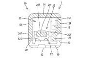
角筒部10は、前後方向に細長い底板12と、底板12の左右両側縁における略前半領域からほぼ直角に立ち上がる一対の側板13L,13Rと、左側板13Lの立ち上がり端縁(上端縁から)における全領域から底板12と略平行に右側板13R(本発明の構成要件である弾性接触片から遠い側の側板)側へ延出する天板14とにより、前後方向に貫通した形態に成形されている。天板14の延出端縁(右端縁)の前端部、後端部及びその中間部分は右側板13Rの上端縁に上から当接されており、天板14の延出端縁のうち右側板13Rの上端縁に当接していない前後2つの領域からは、右側板13Rの内面に沿って(重なるように)下方へ延出する前後2つの係止板15F,15Rが形成されている。前部係止板15Fは全体として方形をなし、その下端縁は角筒部10のほぼ中央高さに位置し、この下端縁の後端部には後縁切欠部16が形成されている。後部係止板15Rは全体として方形をなし、その下端縁は角筒部10における低い位置(底板12に近い位置)に配され、この下端縁の前後方向中央部には下縁切欠部17が形成されている。一方、左側板13Lには、前部係止板15Fの下端縁と対応する略方形の前部係止孔18Fと、後部係止板15Rの下縁切欠部17と対応する略方形の後部係止孔18Rが貫通して形成されている。
The
底板12(弾性接触片25を挟んでタブ進入空間32とは反対側の板部)には、その全幅領域に亘って方形に開口するランス孔19が形成されている。また、左右両側板13L,13Rには、前後方向においてランス孔19と対応する領域の下端縁を、上方へ底板12の上面よりも僅かに高い位置まで切欠することで、側面切欠部20が左右対称に形成されている。この側面切欠部20により、左右両側板13L,13Rの下端縁(下端面)がランス孔19の開口領域に臨む形態となっている。右側板13Rの下端縁部には、そのランス孔19との対応領域を内側(幅方向中央)へ膨出させるように叩き出すことにより侵入規制部21が形成されている。侵入規制部21の側面形状は略方形をなし、侵入規制部の下面から視た形状は台形をなす。尚、上記前部係止板15Fの後縁切欠部16は、侵入規制部21の上縁前端部との干渉を回避するために形成されたものである。
A
また、ランス孔19の開口縁における前端縁には、ランス52の抜止め突起52aを係止させるための抜止め部22が形成されている。この抜止め部22は、底板12におけるランス孔19の開口縁となる端面12Sの一部が抜止め突起52aと対向する向き(後方に面する状態)を保ったままで角筒部10内(上方)へ変位するように、底板12におけるランス孔19の開口縁部を叩き出しによって塑性変形させることによって形成されている。抜止め部22は、角筒部10に対し幅方向(左右方向)において左方へ偏心した配置とされており、この抜止め部22と後述する弾性接触片25とが幅方向において同心の配置となっている。さらに、抜止め部22の上面は、側面切欠部20及び侵入規制部21の下端縁とほぼ同じ高さの平面状をなしている。
A
角筒部10内には弾性接触片25が収容されている。弾性接触片25は、底板12の前端から折り返し状に後方へ片持ち状に延出し、前後方向に細長い形状をなす。弾性接触片25は、底板12の前端に連なる略半円弧状をなす屈曲部26と、この屈曲部26から後方へ延出する延出部27とからなる。延出部27は、屈曲部26の上端から斜め上後方へ延出する前傾部28Fと、前傾部28Fの後端(延出端)から斜め下後方へ延出する後傾部28Rとからなる。弾性接触片25が弾性撓みしていない自由状態では、弾性接触片25の自由端25R(後傾部28Rの後端部)は底板12に対して上方の非接触位置にあるため、弾性接触片25はその前端部において片持ち支持状態となっている。また、弾性接触片25は、屈曲部26を支点とし、主として屈曲部26を弾性撓みさせつつ上下方向へ弾性変形し得るようになっており、下方へ弾性撓みしたときには、弾性接触片25の自由端25R(後傾部28Rの後端)が底板12の上面に当接することで、弾性接触片25が前後両端において支持された状態となる。
An
屈曲部26と前傾部28Fはランス孔19よりも前方の領域に配され、前傾部28Fの後端部(即ち、最も高い部分)には、ドーム状に上方へ叩き出された形態の接点29が形成されている。この接点29も、ランス孔19よりも前方に位置する。後傾部28Rは、ランス孔19の開口縁の前端縁から後部係止板15Rの下縁切欠部17に至る領域に亘っており、後傾部28Rの前端部は、侵入規制部21と対応する高さに配されている。また、弾性接触片25の幅寸法については、屈曲部26と前傾部28Fがほぼ同じ幅寸法とされ、後傾部28Rの前端部と後端部が、前傾部28Fとほぼ同じ寸法とされ、後傾部28Rの前後両端部を除いた領域は、前傾部28Fよりも幅狭となっている。
The
さらに、弾性接触片25の左右両側縁部には、前後一対ずつの突起30F,30Rが幅方向外側へ面一状に張り出す形態で形成されている。左右両前部突起30Fは、互いに対称であり、接点29の近傍、即ち接点29よりも僅かに前方の位置に配されている。この前部突起30Fは、前後方向において前部係止板15Fの下端縁及び前部係止孔18Fと対応するように位置し、弾性接触片25が弾性撓みしていない自由状態では、右側の前部突起30Fの上面が前部係止板15Fの下端縁よりも少し下方の非接触の位置にあるとともに、左側の前部突起30Rの上面が前部係止孔18Fの開口縁の上端縁よりも少し下方の非接触の位置にある。一方、後部突起30Rは、左右対称であり、弾性接触片25の自由端25R(後端)に配されている。この後部突起30Rは、前後方向において後部係止板15Rの下縁切欠部17の下端縁及び後部係止孔18Rと対応するように位置し、弾性接触片25が弾性撓みしていない自由状態では、右側の後部突起30Rの上面が下縁切欠部17の上端縁よりも少し下方の非接触の位置にあるとともに、左側の後部突起30Rの上面が後部係止孔18Rの開口縁の上端縁よりも少し下方の非接触の位置にある。
Further, a pair of front and
かかる弾性接触片25は、左右対称な形状であり、角筒部10及びランス孔19に対し、幅方向において左側へ偏心している。弾性接触片25の幅方向中心は、上記抜止め部22の幅方向中心と合致する。また、下面側からランス孔19を覗くと、弾性接触片25の後傾部28Rの前端側領域がその全幅に亘って露出している。さらに、天板14には、下方へ叩き出すことによってタブ受け部31が形成されているが、このタブ受け部31の幅方向中心も、弾性接触片25と同心となっている。この弾性接触片25の上面とタブ受け部31の下面との間には、前方から角筒部10内に挿入されたタブ54を進入させるためのタブ進入空間32となっている。
The
次に、本実施形態の作用を説明する。
コネクタハウジング50の後方から端子金具Tをキャビティ51内に挿入する過程では、角筒部10の底板12が抜止め突起52aに当接してランス52を下方へ弾性撓みさせる。端子金具Tが正規位置まで挿入されると、ランス52が上方へ弾性復帰して抜止め突起52aがランス孔19内に進入し、抜止め突起52aの前面がランス孔19の抜止め部22に対して後方から係止し、もって、端子金具Tが抜止め状態に保持される。前方から前面板53のタブ挿入口55を通してタブ進入空間32に挿入されたタブ54は、弾性接触片25を弾性撓みさせつつタブ受け部31と接点29との間で弾性的に挟み付けられ、弾性接触片25の弾性復元力によってタブ54と角筒部10が導通可能に接続される。
Next, the operation of this embodiment will be described.
In the process of inserting the terminal fitting T into the
本実施形態においては、次のような作用・効果を奏する。
(1)抜止め部22においては、底板12におけるランス孔19の開口縁となる端面12Sがランス52に当接することで端子金具Tが抜止めされるのであるが、端面12Sの一部が角筒部10内へ変位した形態となっているので、底板の板厚寸法分だけをランス52との係止代としたものと比較すると、係止代が大きく確保されている。
In the present embodiment, the following operations and effects are achieved.
(1) In the retaining
(2)抜止め部22は、底板12の端面12Sの一部がランス52と対向する向きを保ったまま角筒部10内へ変位する形態であって、底板12の外面(下面)と端面12Sとの境界部分はエッジ状の角縁部となっているので、端子金具Tに抜き方向の外力が作用しても、底板の外面(下面)と端面との境界部分が曲面である場合のようにランスが滑って抜止め部から外れる、という虞はない。
(2) The retaining
(3)タブ54が挿入されたときに、弾性接触片25の下方への弾性撓み量がタブ54との正常な接触時よりも大きくなったときには、弾性接触片25における接点29と対応する部分が抜止め部22に対して上から当接し、この当接により、弾性接触片25の弾性限度を超えた過度の撓み変形が規制されるようになっている。このように端子金具Tの抜止め手段である抜止め部22が、弾性接触片25の弾性限度を超えた過度の撓み変形を規制する過度撓み規制機能を兼ね備えているので、抜止め部とは別に専用の過度撓み規制部を設ける場合に比べると、端子金具Tの形状が簡素化されている。
(3) When the amount of elastic deflection of the
(4)ランス孔19から侵入した異物が弾性接触片25を下から押し上げたときには、前部突起30Fが、前部係止板15Fの下端縁と前部係止孔18Fの孔縁に対して下から当接するとともに、後部突起30Rが、後部係止板15Rの下端縁と後部係止孔18Rの孔縁に対して下から当接することにより、タブ進入空間32側(上方)への変位を規制されている。しかも、係止板15F,15Rと係止孔18F,18Rは、ランス孔19よりも前方と後方の2箇所に配されているので、異物の押圧力を受けたときに弾性接触片25が前傾姿勢又は後傾姿勢になる虞はない。これにより、弾性接触片25の撓み支点である屈曲部26が塑性変形することが防止される。
(4) When the foreign matter that has entered from the
(5)ランス孔19よりも前方の前部係止板15Fと前部係止孔18Fが、弾性接触片25におけるタブ54との接点29の近傍に配されているので、たとえ、弾性接触片25における撓み支点(屈曲部26)以外の領域が変形させられたとしても、接点29の位置が変化する虞がなく、タブ54に対して弾性接触片25を適正な接触圧で接触させることができる。
(5) Since the
(6)ランス孔19よりも後方の変位規制部(後部係止板15Rと後部係止孔18R)を弾性接触片25の自由端25Rの近傍に配したので、変位規制部を自由端よりも撓み支点に近い位置(前方の位置)に配したものと比較すると、前側の変位規制部(前部係止板15F及び前部係止孔18F)と後側の変位規制部(後部係止板15R及び後部係止孔18R)との間の前後の間隔が長くなる。したがって、異物の押圧によって弾性接触片25が前後両変位規制部の間で変形させられたときの、弾性撓み量が小さくて済み、弾性接触片25の前後両変位規制部間における塑性変形が生じ難くなっている。
(6) Since the displacement restricting portion (the
(7)底板12には、弾性接触片25を角筒部10外へ臨ませるように開口するランス孔19が開口されているが、右側板13Rには、弾性接触片25に接近し、且つランス孔19の開口領域内に進出する形態の侵入規制部21が形成されているので、この侵入規制部21によりランス孔19における異物の侵入が規制され、ひいては、弾性接触片25に対する異物の干渉が防止されている。
(7) The
(8)侵入規制部21は、幅方向において弾性接触片25の撓み空間外に配されているので、撓み接触片と侵入規制部21との干渉が回避されている。したがって、弾性接触片25の弾性撓み動作に支障を来すことがなく、タブ54と弾性接触片25との接触信頼性が確保される。
(8) Since the
(9)弾性接触片25が角筒部10に対して偏心しているのであるが、これは、弾性接触片25と弾性接触片25から遠い側の側板である右側板13Rとの間にデッドスペースが存在することを意味する。そこで、この点に着目し、このデッドスペースに侵入規制部21を配することで、角筒部10内のデッドスペースの有効利用を図った。
(9) Although the
(10)ランス孔19が角筒部10の全幅に亘って開口し、角筒部10を構成する左右両側板13L,13Rの下端面がランス孔19の開口領域内に露出していることに着目し、右側板13Rにおけるランス孔19に臨む下端縁部を内側へ叩き出すことによって侵入規制部21を形成した。この叩き出しによる形成方法は、切り起こしに比べて加工が簡単であるため、加工コストを低減することができる。
(10) The
<他の実施形態>
本発明は上記記述及び図面によって説明した実施形態に限定されるものではなく、例えば次のような実施態様も本発明の技術的範囲に含まれ、さらに、下記以外にも要旨を逸脱しない範囲内で種々変更して実施することができる。
(1)上記実施形態では侵入規制部を一方の側板のみに設けたが、本発明によれば、侵入規制部を左右両側板に設けてもよい。
(2)上記実施形態では弾性接触片が幅方向において角筒部に対して偏心した位置に配されている場合について説明したが、本発明は、弾性接触片が角筒部に対して偏心せずに幅方向中心を互いに合致させた端子金具にも適用できる。
(3)上記実施形態ではランス孔が角筒部に対して偏心せずに幅方向中心を互いに合致させた場合について説明したが、本発明は、ランス孔が幅方向において角筒部に対して偏心した位置に配されている端子金具にも適用できる。
(4)上記実施形態ではランス孔が角筒部の全幅に亘って開口する場合について説明したが、本発明は、ランス孔の開口幅が角筒部の幅寸法よりも狭い場合にも適用できる。
(5)上記実施形態では侵入規制部を叩き出しによって形成したが、本発明によれば、侵入規制部を切り起こしによって形成してもよい。
<Other embodiments>
The present invention is not limited to the embodiment described with reference to the above description and drawings. For example, the following embodiments are also included in the technical scope of the present invention, and further, within the scope not departing from the gist of the invention other than the following. Various modifications can be made.
(1) Although the intrusion restricting portion is provided only on one side plate in the above embodiment, the intrusion restricting portion may be provided on the left and right side plates according to the present invention.
(2) In the above-described embodiment, the case where the elastic contact piece is disposed at a position eccentric with respect to the rectangular tube part in the width direction has been described. It can also be applied to terminal fittings whose width direction centers match each other.
(3) In the above embodiment, the case where the lance holes are not eccentric with respect to the rectangular tube portion and the centers in the width direction are matched with each other has been described. It can also be applied to terminal fittings arranged at eccentric positions.
(4) In the above embodiment, the case where the lance hole opens over the entire width of the rectangular tube portion has been described, but the present invention can also be applied when the opening width of the lance hole is narrower than the width dimension of the rectangular tube portion. .
(5) Although the intrusion restricting portion is formed by knocking out in the above embodiment, the intrusion restricting portion may be formed by cutting and raising according to the present invention.
T…端子金具
10…角筒部
12…底板(板部)
13R…右側板(弾性接触片から遠い側の側板)
19…ランス孔
21…侵入規制部
25…弾性接触片
50…コネクタハウジング
51…キャビティ
52…ランス
54…タブ
T ...
13R ... right side plate (side plate far from the elastic contact piece)
DESCRIPTION OF
Claims (4)
前記角筒部内には前記タブに対して弾性撓みしつつ接触する弾性接触片が収容されており、
前記角筒部を構成する板部には、前記弾性接触片を前記角筒部外へ臨ませるように開口するランス孔が設けられており、
コネクタハウジングのキャビティ内に挿入された状態では、前記キャビティの内壁に設けた弾性撓み可能なランスに前記ランス孔を係止させることで抜止め状態とされるようになっている端子金具において、
前記角筒部内には前記ランス孔から異物が内部に侵入することを規制する侵入規制部が設けられ、
この侵入規制部は、前記角筒部を構成する板部から、前記弾性接触片に接近し、且つ前記ランス孔に係止する前記ランスと干渉する手前まで前記ランス孔の開口領域内に進出する形態で形成されていることを特徴とする端子金具。 Has a square tube that allows the tab to enter,
An elastic contact piece that comes into contact with the tab while being elastically bent is accommodated in the square tube portion,
The plate portion constituting the square tube portion is provided with a lance hole that opens so that the elastic contact piece faces the outside of the square tube portion,
In the state of being inserted into the cavity of the connector housing, in the terminal fitting adapted to be kept in the unlocked state by locking the lance hole to the elastically deflectable lance provided on the inner wall of the cavity,
An intrusion restricting portion that restricts foreign matter from entering the lance hole is provided in the square tube portion,
The intrusion restricting portion advances into the opening region of the lance hole from the plate portion constituting the rectangular tube portion to a position approaching the elastic contact piece and interfering with the lance locked in the lance hole. A terminal fitting formed in a form.
前記侵入規制部が、前記角筒部を構成する一対の側板のうち前記弾性接触片から遠い側の側板のみに形成されていることを特徴とする請求項1又は請求項2記載の端子金具。 The elastic contact piece is disposed at a position eccentric with respect to the rectangular tube part in the width direction.
3. The terminal fitting according to claim 1, wherein the intrusion restricting portion is formed only on a side plate far from the elastic contact piece among a pair of side plates constituting the rectangular tube portion.
前記側板における前記ランス孔に臨む端縁部を内側へ叩き出すことで、前記侵入規制部が形成されていることを特徴とする請求項1ないし請求項3のいずれかに記載の端子金具。 The lance hole is opened across the entire width of the rectangular tube portion, and the terminal fitting in a form in which the end surfaces of the left and right side plates constituting the rectangular tube portion are exposed in the opening region of the lance hole,
The terminal fitting according to any one of claims 1 to 3, wherein the intrusion restricting portion is formed by knocking an end edge portion of the side plate facing the lance hole inward.
Priority Applications (4)
| Application Number | Priority Date | Filing Date | Title |
|---|---|---|---|
| JP2005026565A JP4392360B2 (en) | 2005-02-02 | 2005-02-02 | Terminal fitting |
| US11/344,758 US7094101B1 (en) | 2005-02-02 | 2006-02-01 | Terminal fitting |
| EP06002203A EP1689052B1 (en) | 2005-02-02 | 2006-02-02 | A terminal fitting and method of forming it |
| DE602006005013T DE602006005013D1 (en) | 2005-02-02 | 2006-02-02 | Terminal contact and method of manufacture |
Applications Claiming Priority (1)
| Application Number | Priority Date | Filing Date | Title |
|---|---|---|---|
| JP2005026565A JP4392360B2 (en) | 2005-02-02 | 2005-02-02 | Terminal fitting |
Publications (2)
| Publication Number | Publication Date |
|---|---|
| JP2006216306A JP2006216306A (en) | 2006-08-17 |
| JP4392360B2 true JP4392360B2 (en) | 2009-12-24 |
Family
ID=36041911
Family Applications (1)
| Application Number | Title | Priority Date | Filing Date |
|---|---|---|---|
| JP2005026565A Active JP4392360B2 (en) | 2005-02-02 | 2005-02-02 | Terminal fitting |
Country Status (4)
| Country | Link |
|---|---|
| US (1) | US7094101B1 (en) |
| EP (1) | EP1689052B1 (en) |
| JP (1) | JP4392360B2 (en) |
| DE (1) | DE602006005013D1 (en) |
Families Citing this family (5)
| Publication number | Priority date | Publication date | Assignee | Title |
|---|---|---|---|---|
| JP5301351B2 (en) * | 2009-05-20 | 2013-09-25 | モレックス インコーポレイテド | Wire-to-board connector and wire connector |
| KR20110081613A (en) * | 2010-01-08 | 2011-07-14 | (주)브이이엔에스 | Automobile |
| JP6551204B2 (en) * | 2015-12-14 | 2019-07-31 | 住友電装株式会社 | Terminal fitting |
| JP7256961B2 (en) * | 2019-09-17 | 2023-04-13 | 住友電装株式会社 | Connectors and terminal fittings |
| JP7447731B2 (en) * | 2020-08-07 | 2024-03-12 | 住友電装株式会社 | connector |
Family Cites Families (8)
| Publication number | Priority date | Publication date | Assignee | Title |
|---|---|---|---|---|
| JP2916001B2 (en) | 1990-07-11 | 1999-07-05 | 矢崎総業株式会社 | Manufacturing method of low insertion force terminal |
| US5235743A (en) * | 1990-07-11 | 1993-08-17 | Yazaki Corporation | Method of manufacturing a pair of terminals having a low friction material on a mating surface to facilitate connection of the terminals |
| JPH09134751A (en) * | 1995-11-08 | 1997-05-20 | Yazaki Corp | Junction structure for box-like portion in terminal metal fitting |
| FR2749441B1 (en) * | 1996-06-03 | 1998-07-10 | Framatome Connectors Int | FEMALE ELECTRIC CONTACT TERMINAL WITH CONTROLLED CONTACT PRESSURE |
| US6280250B1 (en) * | 1998-12-07 | 2001-08-28 | Hon Hai Precision Ind. Co., Ltd. | Electrical connector with terminal retaining means |
| JP2001155810A (en) * | 1999-11-29 | 2001-06-08 | Yazaki Corp | Connector |
| JP4103333B2 (en) * | 2000-12-28 | 2008-06-18 | 住友電装株式会社 | Connector and continuity inspection method in connector |
| JP2002305054A (en) * | 2001-04-04 | 2002-10-18 | Sumitomo Wiring Syst Ltd | Terminal metal fitting |
-
2005
- 2005-02-02 JP JP2005026565A patent/JP4392360B2/en active Active
-
2006
- 2006-02-01 US US11/344,758 patent/US7094101B1/en active Active
- 2006-02-02 DE DE602006005013T patent/DE602006005013D1/en active Active
- 2006-02-02 EP EP06002203A patent/EP1689052B1/en active Active
Also Published As
| Publication number | Publication date |
|---|---|
| US7094101B1 (en) | 2006-08-22 |
| DE602006005013D1 (en) | 2009-03-19 |
| JP2006216306A (en) | 2006-08-17 |
| EP1689052A1 (en) | 2006-08-09 |
| US20060172596A1 (en) | 2006-08-03 |
| EP1689052B1 (en) | 2009-01-28 |
Similar Documents
| Publication | Publication Date | Title |
|---|---|---|
| JP3576488B2 (en) | Female terminal | |
| JP2006216316A (en) | Terminal fitting | |
| JP5233822B2 (en) | Terminal fitting | |
| JP4259472B2 (en) | Terminal fitting | |
| JP6080821B2 (en) | Terminal | |
| JP2011181330A (en) | Terminal fitting | |
| JP6780571B2 (en) | Terminal bracket | |
| JP2006216313A (en) | Terminal fitting | |
| JP4244939B2 (en) | Terminal fitting | |
| JP3642417B2 (en) | Terminal bracket | |
| JP4392360B2 (en) | Terminal fitting | |
| JP4207007B2 (en) | Terminal fitting | |
| JP5482557B2 (en) | Terminal fittings and connectors | |
| EP1689036B1 (en) | A terminal fitting, a connector provided therewith and a method of forming a terminal fitting | |
| JP6540487B2 (en) | Female terminal fitting | |
| JP5440453B2 (en) | connector | |
| JP4304478B2 (en) | connector | |
| JP4442449B2 (en) | Terminal fitting | |
| JP4168911B2 (en) | connector | |
| JP2007141769A (en) | Terminal fitting and manufacturing method of terminal fitting | |
| JP2005216810A (en) | Connector | |
| JP2008218198A (en) | Connector | |
| JP6782735B2 (en) | Terminal fittings and the engagement structure between the terminal fittings and the housing | |
| JP4683287B2 (en) | Terminal fitting | |
| JP2006080004A (en) | Terminal fittings |
Legal Events
| Date | Code | Title | Description |
|---|---|---|---|
| RD04 | Notification of resignation of power of attorney |
Free format text: JAPANESE INTERMEDIATE CODE: A7424 Effective date: 20061025 |
|
| A621 | Written request for application examination |
Free format text: JAPANESE INTERMEDIATE CODE: A621 Effective date: 20070622 |
|
| A977 | Report on retrieval |
Free format text: JAPANESE INTERMEDIATE CODE: A971007 Effective date: 20090701 |
|
| A131 | Notification of reasons for refusal |
Free format text: JAPANESE INTERMEDIATE CODE: A131 Effective date: 20090730 |
|
| A521 | Request for written amendment filed |
Free format text: JAPANESE INTERMEDIATE CODE: A523 Effective date: 20090903 |
|
| TRDD | Decision of grant or rejection written | ||
| A01 | Written decision to grant a patent or to grant a registration (utility model) |
Free format text: JAPANESE INTERMEDIATE CODE: A01 Effective date: 20091001 |
|
| A01 | Written decision to grant a patent or to grant a registration (utility model) |
Free format text: JAPANESE INTERMEDIATE CODE: A01 |
|
| A61 | First payment of annual fees (during grant procedure) |
Free format text: JAPANESE INTERMEDIATE CODE: A61 Effective date: 20091009 |
|
| FPAY | Renewal fee payment (event date is renewal date of database) |
Free format text: PAYMENT UNTIL: 20121016 Year of fee payment: 3 |
|
| R150 | Certificate of patent or registration of utility model |
Ref document number: 4392360 Country of ref document: JP Free format text: JAPANESE INTERMEDIATE CODE: R150 Free format text: JAPANESE INTERMEDIATE CODE: R150 |
|
| FPAY | Renewal fee payment (event date is renewal date of database) |
Free format text: PAYMENT UNTIL: 20121016 Year of fee payment: 3 |
|
| FPAY | Renewal fee payment (event date is renewal date of database) |
Free format text: PAYMENT UNTIL: 20131016 Year of fee payment: 4 |
|
| R250 | Receipt of annual fees |
Free format text: JAPANESE INTERMEDIATE CODE: R250 |
|
| R250 | Receipt of annual fees |
Free format text: JAPANESE INTERMEDIATE CODE: R250 |
|
| R250 | Receipt of annual fees |
Free format text: JAPANESE INTERMEDIATE CODE: R250 |
|
| R250 | Receipt of annual fees |
Free format text: JAPANESE INTERMEDIATE CODE: R250 |
|
| R250 | Receipt of annual fees |
Free format text: JAPANESE INTERMEDIATE CODE: R250 |
|
| R250 | Receipt of annual fees |
Free format text: JAPANESE INTERMEDIATE CODE: R250 |
|
| R250 | Receipt of annual fees |
Free format text: JAPANESE INTERMEDIATE CODE: R250 |
|
| R250 | Receipt of annual fees |
Free format text: JAPANESE INTERMEDIATE CODE: R250 |
|
| R250 | Receipt of annual fees |
Free format text: JAPANESE INTERMEDIATE CODE: R250 |
|
| R250 | Receipt of annual fees |
Free format text: JAPANESE INTERMEDIATE CODE: R250 |
|
| R250 | Receipt of annual fees |
Free format text: JAPANESE INTERMEDIATE CODE: R250 |
|
| R250 | Receipt of annual fees |
Free format text: JAPANESE INTERMEDIATE CODE: R250 |