EP1689052A1 - A terminal fitting and method of forming it - Google Patents
A terminal fitting and method of forming it Download PDFInfo
- Publication number
- EP1689052A1 EP1689052A1 EP06002203A EP06002203A EP1689052A1 EP 1689052 A1 EP1689052 A1 EP 1689052A1 EP 06002203 A EP06002203 A EP 06002203A EP 06002203 A EP06002203 A EP 06002203A EP 1689052 A1 EP1689052 A1 EP 1689052A1
- Authority
- EP
- European Patent Office
- Prior art keywords
- contact piece
- resilient contact
- tube portion
- locking hole
- terminal fitting
- Prior art date
- Legal status (The legal status is an assumption and is not a legal conclusion. Google has not performed a legal analysis and makes no representation as to the accuracy of the status listed.)
- Granted
Links
- 238000000034 method Methods 0.000 title claims description 8
- 238000004049 embossing Methods 0.000 claims description 10
- 238000006073 displacement reaction Methods 0.000 claims description 8
- 230000013011 mating Effects 0.000 claims description 8
- 230000000717 retained effect Effects 0.000 claims description 7
- 239000000463 material Substances 0.000 claims description 2
- 238000005452 bending Methods 0.000 description 5
- 238000003780 insertion Methods 0.000 description 2
- 230000037431 insertion Effects 0.000 description 2
- 238000007493 shaping process Methods 0.000 description 2
- 230000001419 dependent effect Effects 0.000 description 1
- 230000000694 effects Effects 0.000 description 1
- 239000002184 metal Substances 0.000 description 1
- 230000000149 penetrating effect Effects 0.000 description 1
- 229920003002 synthetic resin Polymers 0.000 description 1
- 239000000057 synthetic resin Substances 0.000 description 1
Images


Classifications
-
- H—ELECTRICITY
- H01—ELECTRIC ELEMENTS
- H01R—ELECTRICALLY-CONDUCTIVE CONNECTIONS; STRUCTURAL ASSOCIATIONS OF A PLURALITY OF MUTUALLY-INSULATED ELECTRICAL CONNECTING ELEMENTS; COUPLING DEVICES; CURRENT COLLECTORS
- H01R13/00—Details of coupling devices of the kinds covered by groups H01R12/70 or H01R24/00 - H01R33/00
- H01R13/40—Securing contact members in or to a base or case; Insulating of contact members
- H01R13/42—Securing in a demountable manner
- H01R13/422—Securing in resilient one-piece base or case, e.g. by friction; One-piece base or case formed with resilient locking means
-
- H—ELECTRICITY
- H01—ELECTRIC ELEMENTS
- H01R—ELECTRICALLY-CONDUCTIVE CONNECTIONS; STRUCTURAL ASSOCIATIONS OF A PLURALITY OF MUTUALLY-INSULATED ELECTRICAL CONNECTING ELEMENTS; COUPLING DEVICES; CURRENT COLLECTORS
- H01R43/00—Apparatus or processes specially adapted for manufacturing, assembling, maintaining, or repairing of line connectors or current collectors or for joining electric conductors
- H01R43/16—Apparatus or processes specially adapted for manufacturing, assembling, maintaining, or repairing of line connectors or current collectors or for joining electric conductors for manufacturing contact members, e.g. by punching and by bending
-
- H—ELECTRICITY
- H01—ELECTRIC ELEMENTS
- H01R—ELECTRICALLY-CONDUCTIVE CONNECTIONS; STRUCTURAL ASSOCIATIONS OF A PLURALITY OF MUTUALLY-INSULATED ELECTRICAL CONNECTING ELEMENTS; COUPLING DEVICES; CURRENT COLLECTORS
- H01R13/00—Details of coupling devices of the kinds covered by groups H01R12/70 or H01R24/00 - H01R33/00
- H01R13/02—Contact members
- H01R13/10—Sockets for co-operation with pins or blades
- H01R13/11—Resilient sockets
- H01R13/113—Resilient sockets co-operating with pins or blades having a rectangular transverse section
Definitions
- the present invention relates to a terminal fitting and to a method of forming it.
- a terminal fitting is known from Japanese Unexamined Patent Publication No. H04-115475.
- This terminal fitting includes a rectangular tube portion into which a tab is insertable, wherein a resilient contact piece to be held in contact with the tab while undergoing a resilient deformation is accommodated in the rectangular tube portion and a locking hole is formed in a plate portion forming the rectangular tube portion.
- Such a terminal fitting is inserted into a cavity of a connector housing and is retained therein by the engagement of the locking hole with a resiliently deformable locking portion provided at an inner wall of the cavity.
- part of the resilient contact piece can be seen through the locking hole from the outside of the rectangular tube portion.
- an external matter intrudes into the rectangular tube portion through the locking hole, it may interfere with the resilient contact piece to deform the resilient contact piece.
- the present invention was developed in view of the above problem, an object thereof is to prevent the intrusion of an external matter into a tube portion.
- a terminal fitting comprising:
- the intrusion restricting portion is formed at the plate portion of the tube portion to be at least partly located in the opening area of the locking hole, the intrusion of an external matter through the locking hole can be restricted by the intrusion restricting portion, which in turn can prevent the interference of the external matter with the resilient contact piece.
- a terminal fitting comprising:
- the intrusion restricting portion is arranged outside a deformation space for the resilient contact piece.
- the intrusion restricting portion is located outside the deformation space for the resilient contact piece, the mutual interference of the resilient contact piece and the intrusion restricting portion can be avoided.
- the resilient deformation of the resilient contact piece is not hindered, thereby ensuring contact reliability of the mating contact portion or element (or tab) and the resilient contact piece.
- the resilient contact piece is arranged at such a position where the widthwise center thereof is deviated from that of the tube portion.
- the intrusion restricting portion is formed only at a side plate more distant from the resilient contact piece out of a pair of side plates forming the tube portion.
- the resilient contact piece is arranged at such a position where the widthwise center thereof is deviated from that of the (preferably substantially rectangular or polygonal) tube portion, and the intrusion restricting portion is formed only at a side plate more distant from the resilient contact piece out of a pair of side plates forming the (rectangular/polygonal) tube portion.
- the intrusion restricting portion is arranged in this dead space to effectively utilize a space in the (rectangular/polygonal) tube portion.
- the locking hole is formed over the substantially entire width of the tube portion.
- end surfaces of lateral side surfaces forming the tube portion are exposed in the opening area of the locking hole.
- the intrusion restricting portion is formed by embossing an end edge portion of the side plate substantially facing the locking hole to project substantially inward.
- the locking hole is formed over the entire width of the rectangular tube portion, end surfaces of left and right side surfaces forming the rectangular tube portion are exposed in the opening area of the locking hole, and the intrusion restricting portion is formed by embossing an end edge portion of the side plate facing the locking hole to project inward.
- the end edge portion of this side plate is embossed to form the intrusion restricting portion. Since this method by embossing is easily workable as compared to cutting and bending. Therefore, a processing cost can be reduced.
- a displacement of the resilient contact piece toward a portion of the tube portion is restricted by bringing a portion of the resilient contact piece into contact with a locking plate or locking recess.
- a method of forming or shaping a terminal fitting comprising the following steps:
- the intrusion restricting portion is formed by embossing an end edge portion of the side plate substantially facing the locking hole to project substantially inward.
- the connector housing 50 into which one or more terminal fittings T of this embodiment are to be at least partly accommodated is first described.
- the connector housing 50 is made e.g. of a synthetic resin and internally formed with one or more, preferably a plurality of cavities 51 penetrating the connector housing 50 substantially in forward and backward directions, wherein each cavity 51 is formed with a (preferably substantially cantilever-shaped) locking portion 52 projecting substantially forward along or at the bottom wall thereof and having a retaining projection 52a on the inner (or upper) surface thereof (surface substantially facing the cavity 51).
- a front plate 53 is to be mounted on the front surface of the connector housing 50, and one or more tabs 54 of male terminal fittings mounted in an unillustrated connector are at least partly inserted from front through tab insertion openings 55 formed in the front plate 53 to at least partly enter the cavities 51.
- the terminal fitting T is formed by applying bending, folding, embossing, shaping and the like to a conductive (preferably metal) sheet stamped or cut out into a specified (predetermined or predeterminable) shape as shown in FIG. 10 and substantially narrow and long along forward and backward directions as a whole.
- a front portion (preferably a substantially front half) of the terminal fitting T is or comprises a (preferably substantially rectangular or polygonal) tube portion 10 and a rear portion (preferably a substantially rear half) thereof is or comprises a wire connecting portion 11 preferably in the form of one or more open barrels.
- the wire connecting portion 11 is to be connected, preferably crimped or bent or folded into electrical connection, with an end (front end) of a wire W.
- the (preferably substantially rectangular or polygonal) tube portion 10 is formed into a shape substantially hollow along forward and backward directions by a bottom or base plate 12 substantially narrow and long along forward and backward directions, one or more, preferably a pair of side plates 13L, 13R standing up or projecting at an angle different from 0° or 180°, preferably substantially at right angle from front areas (preferably from substantially front half areas) of the lateral (left and/or right) edge(s) of the bottom or base plate 12, and a ceiling or top plate 14 extending from the (preferably substantially entire) projecting edge (upper edge) of one lateral side plate (e.g.
- the left side plate 13L at an angle different from 0° or 180°, preferably substantially normal thereto, preferably substantially toward the opposite lateral side plate e.g. the right side plate 13R (as a preferred side plate more distant from a resilient contact piece) preferably substantially in parallel with the bottom or base plate 12.
- a front end portion, a rear end portion and an intermediate portion of an extending edge (right edge) of the ceiling plate 14 at least partly is substantially in contact with the upper or distal edge of the lateral (right) side plate 13R from above.
- One or more, preferably two front and/or rear locking plates 15F, 15R extend at an angle different from 0° or 180°, preferably substantially inwardly or downward along (so as to at least partly overlap) the inner surface of the lateral (right) side plate 13R in one or more, preferably two front and/or rear areas of the extending edge of the ceiling plate 14 that preferably are not substantially in contact with the upper edge of the right side plate 13R.
- the front locking plate 15F preferably is substantially rectangular as a whole (see e.g. FIG. 5), and the bottom edge thereof is located at an intermediate height position (preferably substantially at the center height) of the rectangular tube portion 10, wherein a rear notch 16 is formed preferably at or towards the rear end of this bottom edge.
- the rear locking plate 15R preferably has, as a whole, a substantially rectangular shape and the bottom edge thereof is located at a lower position in the rectangular tube portion 10 as compared to the bottom edge of the front locking plate (preferably at a position near the bottom plate 12), wherein a bottom notch 17 is formed preferably at an intermediate position (more preferably at a middle part) of this bottom edge with respect to forward and backward directions.
- the lateral (left) side plate 13L is formed with a (preferably substantially rectangular) front locking hole 18F substantially corresponding to the bottom edge of the front locking plate 15F and/or a (preferably substantially rectangular) rear locking hole 18R substantially corresponding to the bottom notch 17 of the rear locking plate 15R.
- a (preferably substantially rectangular) locking hole 19 is formed preferably over the substantially entire width in the bottom plate 12 (plate portion at a side of a resilient contact piece 25 preferably substantially opposite to a tab entrance space 32).
- the lateral (left and right) side plates 13L, 13R preferably have the bottom edges notched up to a position slightly higher than the upper surface of the bottom plate 12 in areas substantially corresponding to the locking hole 19 with respect to forward and backward directions, thereby preferably transversely symmetrically forming side notches 20.
- the bottom edges (bottom end surfaces) of the lateral (left and right) side plates 13L, 13R substantially face an opening area of the locking hole 19 by forming the side notches 20.
- the bottom edge of the lateral (right) side plate 13R preferably is embossed or bent to project inward (substantially toward the widthwise center) in an area substantially corresponding to the locking hole 19, thereby forming an intrusion restricting portion 21.
- the intrusion restricting portion 21 has a substantially rectangular side view (see e.g. FIG. 3) and/or a trapezoidal bottom view (see e.g. FIG. 4). It should be noted that the rear notch 16 of the front locking plate 15F preferably is formed to avoid the interference with the front upper end of the intrusion restricting portion 21.
- a retaining portion 22 to be engaged with the retaining projection 52a of the locking portion 52 is formed at or close to the front edge of the locking hole 19.
- This retaining portion 22 preferably is formed by plastically deforming the opening edge of the locking hole 19 in the bottom or base plate 12 preferably through stamping or embossing so that part of an end surface 12S serving as the opening edge of the locking hole 19 is displaced substantially inward of the rectangular tube portion 10 (upward) and/or is held substantially faced in such a direction as to be substantially opposed to the retaining projection 52a (faced backward).
- the retaining portion 22 is arranged at such a position where the widthwise (transverse) center thereof is deviated or offset laterally (e.g.
- the upper or inner surface of the retaining portion 22 preferably is a substantially flat surface substantially at the same height as the side notches 20 and/or the bottom edge of the intrusion restricting portion 21.
- the resilient contact piece 25 is at least partly accommodated in the rectangular tube portion 10. As shown in FIG. 5, the resilient contact piece 25 is bent or folded back at the front end of the bottom or base plate 12 to preferably cantilever substantially backward and substantially has a shape narrow and long along forward and backward directions.
- the resilient contact piece 25 preferably is comprised of a (preferably substantially arcuate) bent portion 26 connected with the front end of the bottom plate 12 and an extending portion 27 extending substantially backward from the bent portion 26.
- the extending portion 27 has a front inclined portion 28F extending obliquely upward or inwardly to the back from the upper end of the bent portion 26 and a backward inclined portion 28R extending obliquely downward or outward to the back from the rear end (extending end) of the forward inclined portion 28F.
- a free end 25A of the resilient contact piece 25 (rear end of the backward inclined portion 28R) preferably is at a noncontact position above the bottom plate 12, wherefore the resilient contact piece 25 preferably is supported only at the front end thereof.
- the resilient contact piece 25 is resiliently displaceable in a direction intersecting the forward and backward directions (substantially upward and downward) preferably with at least the bent portion 26 as a supporting point while mainly bending the bent portion 26.
- the resilient contact piece 25 is resiliently displaced substantially downward or outward, the free end 25A thereof (rear end of the backward inclined portion 28R) comes substantially into contact with the inner surface of the bottom plate 12, whereby the resilient contact piece 25 preferably is supported at both front and rear ends.
- the bent portion 26 and the forward inclined portion 28F are located in an area before the locking hole 19, and the rear end (i.e. highest portion) of the forward inclined portion 28F is embossed to project upward or towards a space where a tab is to be at least partly inserted, thereby forming a (preferably substantially dome-shaped) contact point 29.
- This contact point 29 preferably is (also) located before the locking hole 19.
- the rear inclined portion 28R extends from the front edge of the locking hole 19 to the bottom notch 17 of the rear locking plate 15R, and the front end thereof is located at such a height preferably substantially corresponding to the intrusion restricting portion 21.
- the width of the resilient contact piece 25 preferably is such that the bent portion 26 and the forward inclined portion 28F have substantially the same widths, the front and rear ends of the backward inclined portion 28R preferably have substantially the same widths as the forward inclined portion 28F, and/or the backward inclined portion 28R preferably is narrower than the forward inclined portion 28F except at the front and rear ends thereof.
- One or more, preferably a pair of front projections 30F and one or more, preferably a pair of rear projections 30R are formed to bulge out along width direction from the lateral (left and/or right) edge(s) of the resilient contact piece 25 substantially in flush with the resilient contact piece 25.
- the left and right front projections 30F preferably are substantially symmetrical to each other and located in the vicinity of the contact point 29, i.e. preferably slightly before the contact point 29.
- the front projections 30F are so located as to substantially correspond to the bottom edge of the front locking plate 15F and the front locking hole 18F with respect to forward and backward directions.
- the upper surface of the lateral (right) front projection 30F is located at a substantially noncontact position slightly below the bottom edge of the front locking plate 15F and that of the other lateral (left) front projection 30R is located at a substantially noncontact position slightly below the upper edge of the front locking hole 18F.
- the rear projections 30R preferably are substantially transversely symmetrical to each other and arranged at the free end 25R (rear end) of the resilient contact piece 25. The rear projections 30R are so located as to substantially correspond to the upper edge of the bottom notch 17 of the rear locking plate 15R and the rear locking hole 18R.
- the upper surface of the lateral (right) rear projection 30R is located at a substantially noncontact position slightly below the upper edge of the bottom notch 17 and/or that of the other lateral (left) rear projection 30R is located at a substantially noncontact position slightly below the upper edge of the rear locking hole 18R.
- Such a resilient contact piece 25 preferably is substantially transversely symmetrical and/or the widthwise center thereof is deviated or offset laterally e.g. to left from those of the (rectangular) tube portion 10 and the locking hole 19.
- the widthwise center of the resilient contact piece 25 preferably substantially coincides with that of the retaining portion 22.
- a front area of the backward inclined portion 28R of the resilient contact piece 25 is exposed preferably over the substantially entire width.
- the ceiling plate 14 is struck or embossed to project downward or inwardly to form a tab receiving portion 31.
- the widthwise center of the tab receiving portion 31 preferably (also) substantially coincides with that of the resilient contact piece 25.
- the tab entrance space 32 for permitting the at least partial entrance of the tab 54 at least partly inserted into the (rectangular) tube portion 10 from front is defined between the upper or inner surface of the resilient contact piece 25 and the lower or inner surface of the tab receiving portion 31.
- the bottom or base plate 12 of the (preferably substantially rectangular or polygonal) tube portion 10 comes substantially into contact with the retaining projection 52a to resiliently deform the locking portion 52 downward or outwardly.
- the locking portion 52 is resiliently at least partly restored upward or inwardly to at least partly fit the retaining projection 52a into the locking hole 19, whereby the front surface of the retaining projection 52a is engaged with the retaining portion 22 of the locking hole 19 from a withdrawing direction, preferably substantially from behind.
- the terminal fitting T is retained.
- the tab 54 at least partly inserted into the tab entrance space 32 through the tab insertion opening 55 of the front plate 53 from front preferably is resiliently squeezed between the tab receiving portion 31 and the contact point 29 while resiliently deforming the resilient contact piece 25, and the tab 54 and the rectangular tube portion 10 are electrically connected by a resilient restoring force of the resilient contact piece 25.
- This embodiment has following functions and effects.
- a resilient contact piece 25 to be brought into contact with a tab 54 while undergoing a resilient deformation is at least partly accommodated in a (preferably substantially rectangular or polygonal) tube portion 10, and a bottom or base plate 12 of the (rectangular/polygonal) tube portion 10 is formed with such a locking hole 19 as to at least partly expose the resilient contact piece 25 to the outside of the rectangular tube portion 10.
- a side plate 13R of the (rectangular/polygonal) tube portion 10 is provided with an intrusion restricting portion 21 in the vicinity of the resilient contact piece 25 and located in an opening area of the locking hole 19, the intrusion of an external matter through the locking hole 19 can be restricted by the intrusion restricting portion 21, thereby preventing the interference of the external matter with the resilient contact piece 25.
Landscapes
- Engineering & Computer Science (AREA)
- Manufacturing & Machinery (AREA)
- Connector Housings Or Holding Contact Members (AREA)
Abstract
Description
- The present invention relates to a terminal fitting and to a method of forming it.
- A terminal fitting is known from Japanese Unexamined Patent Publication No. H04-115475. This terminal fitting includes a rectangular tube portion into which a tab is insertable, wherein a resilient contact piece to be held in contact with the tab while undergoing a resilient deformation is accommodated in the rectangular tube portion and a locking hole is formed in a plate portion forming the rectangular tube portion. Such a terminal fitting is inserted into a cavity of a connector housing and is retained therein by the engagement of the locking hole with a resiliently deformable locking portion provided at an inner wall of the cavity.
- In this terminal fitting, part of the resilient contact piece can be seen through the locking hole from the outside of the rectangular tube portion. Thus, when an external matter intrudes into the rectangular tube portion through the locking hole, it may interfere with the resilient contact piece to deform the resilient contact piece.
- The present invention was developed in view of the above problem, an object thereof is to prevent the intrusion of an external matter into a tube portion.
- This object is solved according to the invention by the features of the independent claims. Preferred embodiments of the invention are subject of the dependent claims.
- According to the invention, there is provided a terminal fitting, comprising:
- a tube portion enabling the at least partial entrance of a mating contact portion such as a tab thereinto,
- a resilient contact piece at least partly accommodated in the tube portion and to be held in contact with the mating contact portion while being resiliently deformed, and
- a locking hole formed in a plate portion forming (part of) the tube portion in such a manner as to at least partly expose the resilient contact piece to the outside of the tube portion, the locking hole being engageable with a resiliently deformable locking portion of a connector housing to be retained,
- Since the intrusion restricting portion is formed at the plate portion of the tube portion to be at least partly located in the opening area of the locking hole, the intrusion of an external matter through the locking hole can be restricted by the intrusion restricting portion, which in turn can prevent the interference of the external matter with the resilient contact piece.
- According to a preferred embodiment of the invention, there is provided a terminal fitting, comprising:
- a rectangular tube portion enabling the entrance of a tab thereinto,
- a resilient contact piece accommodated in the rectangular tube portion and to be held in contact with the tab while being resiliently deformed, and
- a locking hole formed in a plate portion forming the rectangular tube portion in such a manner as to expose the resilient contact piece to the outside of the rectangular tube portion,
- the terminal fitting inserted in a cavity of a connector housing being retained therein by the engagement of the locking hole with a resiliently deformable locking portion provided at an inner wall of the cavity,
- Preferably, the intrusion restricting portion is arranged outside a deformation space for the resilient contact piece.
- Since the intrusion restricting portion is located outside the deformation space for the resilient contact piece, the mutual interference of the resilient contact piece and the intrusion restricting portion can be avoided. Thus, the resilient deformation of the resilient contact piece is not hindered, thereby ensuring contact reliability of the mating contact portion or element (or tab) and the resilient contact piece.
- Preferably, the resilient contact piece is arranged at such a position where the widthwise center thereof is deviated from that of the tube portion.
- Further preferably, the intrusion restricting portion is formed only at a side plate more distant from the resilient contact piece out of a pair of side plates forming the tube portion.
- Most preferably, the resilient contact piece is arranged at such a position where the widthwise center thereof is deviated from that of the (preferably substantially rectangular or polygonal) tube portion, and the intrusion restricting portion is formed only at a side plate more distant from the resilient contact piece out of a pair of side plates forming the (rectangular/polygonal) tube portion.
- Paying attention to the presence of a dead space between the resilient contact piece and one side plate because of the deviation of the resilient contact piece from the (rectangular/polygonal) tube portion, the intrusion restricting portion is arranged in this dead space to effectively utilize a space in the (rectangular/polygonal) tube portion.
- According to a further preferred embodiment of the invention, the locking hole is formed over the substantially entire width of the tube portion.
- Preferably, end surfaces of lateral side surfaces forming the tube portion are exposed in the opening area of the locking hole.
- Further preferably, the intrusion restricting portion is formed by embossing an end edge portion of the side plate substantially facing the locking hole to project substantially inward.
- Still further preferably, the locking hole is formed over the entire width of the rectangular tube portion,
end surfaces of left and right side surfaces forming the rectangular tube portion are exposed in the opening area of the locking hole, and
the intrusion restricting portion is formed by embossing an end edge portion of the side plate facing the locking hole to project inward. - Paying attention to the end surface of the side plate exposed in the opening area of the locking hole, the end edge portion of this side plate is embossed to form the intrusion restricting portion. Since this method by embossing is easily workable as compared to cutting and bending. Therefore, a processing cost can be reduced.
- Most preferably, a displacement of the resilient contact piece toward a portion of the tube portion is restricted by bringing a portion of the resilient contact piece into contact with a locking plate or locking recess.
- According to the invention, there is further provided a method of forming or shaping a terminal fitting, in particular according to the invention or a preferred embodiment thereof, comprising the following steps:
- providing a plate material being shaped such as to provide a tube portion having a resilient contact piece at least partly accommodated in the tube portion,
- providing a locking hole in a plate portion forming the tube portion in such a manner as to at least partly expose the resilient contact piece to the outside of the tube portion, the locking hole being engageable with a resiliently deformable locking portion of a connector housing to be retained, and
- providing at least one intrusion restricting portion formed near the resilient contact piece in or at a plate portion forming part of the tube portion to be at least partly located in an opening area of the locking hole.
- According to a preferred embodiment of the invention, the intrusion restricting portion is formed by embossing an end edge portion of the side plate substantially facing the locking hole to project substantially inward.
- These and other objects, features and advantages of the present invention will become more apparent upon reading of the following detailed description of preferred embodiments and accompanying drawings. It should be understood that even though embodiments are separately described, single features thereof may be combined to additional embodiments.
- FIG. 1 is a right side view of a terminal fitting according to one embodiment of the invention,
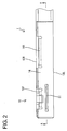
- FIG. 2 is a plan view of the terminal fitting,
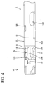
- FIG. 3 is a left side view of the terminal fitting,
- FIG. 4 is a bottom view of the terminal fitting,
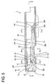
- FIG. 5 is a section along A-A of FIG. 2,
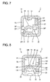
- FIG. 6 is a section along B-B of FIG. 5,
- FIG. 7 is a section along C-C of FIG. 5,
- FIG. 8 is a section along D-D of FIG. 5,
- FIG. 9 is a section along E-E of FIG. 5,
- FIG. 10 is a development of the terminal fitting,
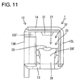
- FIG. 11 is a front view of the terminal fitting, and
- FIG. 12 is a section showing a state where a tab is connected with the terminal fitting.
- One preferred embodiment of the present invention is described with reference to FIGS. 1 to 12. A connector housing 50 into which one or more terminal fittings T of this embodiment are to be at least partly accommodated is first described. The
connector housing 50 is made e.g. of a synthetic resin and internally formed with one or more, preferably a plurality ofcavities 51 penetrating the connector housing 50 substantially in forward and backward directions, wherein eachcavity 51 is formed with a (preferably substantially cantilever-shaped)locking portion 52 projecting substantially forward along or at the bottom wall thereof and having aretaining projection 52a on the inner (or upper) surface thereof (surface substantially facing the cavity 51). Afront plate 53 is to be mounted on the front surface of theconnector housing 50, and one ormore tabs 54 of male terminal fittings mounted in an unillustrated connector are at least partly inserted from front throughtab insertion openings 55 formed in thefront plate 53 to at least partly enter thecavities 51. - Next, the terminal fitting T is described. The terminal fitting T is formed by applying bending, folding, embossing, shaping and the like to a conductive (preferably metal) sheet stamped or cut out into a specified (predetermined or predeterminable) shape as shown in FIG. 10 and substantially narrow and long along forward and backward directions as a whole. A front portion (preferably a substantially front half) of the terminal fitting T is or comprises a (preferably substantially rectangular or polygonal)
tube portion 10 and a rear portion (preferably a substantially rear half) thereof is or comprises awire connecting portion 11 preferably in the form of one or more open barrels. Thewire connecting portion 11 is to be connected, preferably crimped or bent or folded into electrical connection, with an end (front end) of a wire W. - The (preferably substantially rectangular or polygonal)
tube portion 10 is formed into a shape substantially hollow along forward and backward directions by a bottom orbase plate 12 substantially narrow and long along forward and backward directions, one or more, preferably a pair ofside plates base plate 12, and a ceiling ortop plate 14 extending from the (preferably substantially entire) projecting edge (upper edge) of one lateral side plate (e.g. theleft side plate 13L) at an angle different from 0° or 180°, preferably substantially normal thereto, preferably substantially toward the opposite lateral side plate e.g. theright side plate 13R (as a preferred side plate more distant from a resilient contact piece) preferably substantially in parallel with the bottom orbase plate 12. A front end portion, a rear end portion and an intermediate portion of an extending edge (right edge) of theceiling plate 14 at least partly is substantially in contact with the upper or distal edge of the lateral (right)side plate 13R from above. One or more, preferably two front and/orrear locking plates side plate 13R in one or more, preferably two front and/or rear areas of the extending edge of theceiling plate 14 that preferably are not substantially in contact with the upper edge of theright side plate 13R. Thefront locking plate 15F preferably is substantially rectangular as a whole (see e.g. FIG. 5), and the bottom edge thereof is located at an intermediate height position (preferably substantially at the center height) of therectangular tube portion 10, wherein arear notch 16 is formed preferably at or towards the rear end of this bottom edge. Therear locking plate 15R preferably has, as a whole, a substantially rectangular shape and the bottom edge thereof is located at a lower position in therectangular tube portion 10 as compared to the bottom edge of the front locking plate (preferably at a position near the bottom plate 12), wherein abottom notch 17 is formed preferably at an intermediate position (more preferably at a middle part) of this bottom edge with respect to forward and backward directions. On the other hand, the lateral (left)side plate 13L is formed with a (preferably substantially rectangular)front locking hole 18F substantially corresponding to the bottom edge of thefront locking plate 15F and/or a (preferably substantially rectangular)rear locking hole 18R substantially corresponding to thebottom notch 17 of therear locking plate 15R. - A (preferably substantially rectangular) locking
hole 19 is formed preferably over the substantially entire width in the bottom plate 12 (plate portion at a side of aresilient contact piece 25 preferably substantially opposite to a tab entrance space 32). The lateral (left and right)side plates bottom plate 12 in areas substantially corresponding to the lockinghole 19 with respect to forward and backward directions, thereby preferably transversely symmetrically formingside notches 20. The bottom edges (bottom end surfaces) of the lateral (left and right)side plates hole 19 by forming theside notches 20. The bottom edge of the lateral (right)side plate 13R preferably is embossed or bent to project inward (substantially toward the widthwise center) in an area substantially corresponding to the lockinghole 19, thereby forming anintrusion restricting portion 21. Theintrusion restricting portion 21 has a substantially rectangular side view (see e.g. FIG. 3) and/or a trapezoidal bottom view (see e.g. FIG. 4). It should be noted that therear notch 16 of thefront locking plate 15F preferably is formed to avoid the interference with the front upper end of theintrusion restricting portion 21. - Further, a retaining
portion 22 to be engaged with the retainingprojection 52a of the lockingportion 52 is formed at or close to the front edge of the lockinghole 19. This retainingportion 22 preferably is formed by plastically deforming the opening edge of the lockinghole 19 in the bottom orbase plate 12 preferably through stamping or embossing so that part of anend surface 12S serving as the opening edge of the lockinghole 19 is displaced substantially inward of the rectangular tube portion 10 (upward) and/or is held substantially faced in such a direction as to be substantially opposed to the retainingprojection 52a (faced backward). The retainingportion 22 is arranged at such a position where the widthwise (transverse) center thereof is deviated or offset laterally (e.g. to left) from that of the (rectangular)tube portion 10, and the widthwise center thereof preferably substantially coincides with that of theresilient contact piece 25 to be described later. The upper or inner surface of the retainingportion 22 preferably is a substantially flat surface substantially at the same height as theside notches 20 and/or the bottom edge of theintrusion restricting portion 21. - The
resilient contact piece 25 is at least partly accommodated in therectangular tube portion 10. As shown in FIG. 5, theresilient contact piece 25 is bent or folded back at the front end of the bottom orbase plate 12 to preferably cantilever substantially backward and substantially has a shape narrow and long along forward and backward directions. Theresilient contact piece 25 preferably is comprised of a (preferably substantially arcuate)bent portion 26 connected with the front end of thebottom plate 12 and an extendingportion 27 extending substantially backward from thebent portion 26. The extendingportion 27 has a frontinclined portion 28F extending obliquely upward or inwardly to the back from the upper end of thebent portion 26 and a backwardinclined portion 28R extending obliquely downward or outward to the back from the rear end (extending end) of the forward inclinedportion 28F. In a free state where theresilient contact piece 25 is not resiliently displaced, a free end 25A of the resilient contact piece 25 (rear end of the backwardinclined portion 28R) preferably is at a noncontact position above thebottom plate 12, wherefore theresilient contact piece 25 preferably is supported only at the front end thereof. Theresilient contact piece 25 is resiliently displaceable in a direction intersecting the forward and backward directions (substantially upward and downward) preferably with at least thebent portion 26 as a supporting point while mainly bending thebent portion 26. When theresilient contact piece 25 is resiliently displaced substantially downward or outward, the free end 25A thereof (rear end of the backwardinclined portion 28R) comes substantially into contact with the inner surface of thebottom plate 12, whereby theresilient contact piece 25 preferably is supported at both front and rear ends. - The
bent portion 26 and the forwardinclined portion 28F are located in an area before the lockinghole 19, and the rear end (i.e. highest portion) of the forward inclinedportion 28F is embossed to project upward or towards a space where a tab is to be at least partly inserted, thereby forming a (preferably substantially dome-shaped)contact point 29. Thiscontact point 29 preferably is (also) located before the lockinghole 19. The rear inclinedportion 28R extends from the front edge of the lockinghole 19 to thebottom notch 17 of therear locking plate 15R, and the front end thereof is located at such a height preferably substantially corresponding to theintrusion restricting portion 21. The width of theresilient contact piece 25 preferably is such that thebent portion 26 and the forwardinclined portion 28F have substantially the same widths, the front and rear ends of the backwardinclined portion 28R preferably have substantially the same widths as the forwardinclined portion 28F, and/or the backwardinclined portion 28R preferably is narrower than the forwardinclined portion 28F except at the front and rear ends thereof. - One or more, preferably a pair of
front projections 30F and one or more, preferably a pair ofrear projections 30R are formed to bulge out along width direction from the lateral (left and/or right) edge(s) of theresilient contact piece 25 substantially in flush with theresilient contact piece 25. The left and rightfront projections 30F preferably are substantially symmetrical to each other and located in the vicinity of thecontact point 29, i.e. preferably slightly before thecontact point 29. Thefront projections 30F are so located as to substantially correspond to the bottom edge of thefront locking plate 15F and thefront locking hole 18F with respect to forward and backward directions. In the free state where theresilient contact piece 25 is not resiliently displaced, the upper surface of the lateral (right)front projection 30F is located at a substantially noncontact position slightly below the bottom edge of thefront locking plate 15F and that of the other lateral (left)front projection 30R is located at a substantially noncontact position slightly below the upper edge of thefront locking hole 18F. On the other hand, therear projections 30R preferably are substantially transversely symmetrical to each other and arranged at thefree end 25R (rear end) of theresilient contact piece 25. Therear projections 30R are so located as to substantially correspond to the upper edge of thebottom notch 17 of therear locking plate 15R and therear locking hole 18R. In the free state where theresilient contact piece 25 is not resiliently displaced, the upper surface of the lateral (right)rear projection 30R is located at a substantially noncontact position slightly below the upper edge of thebottom notch 17 and/or that of the other lateral (left)rear projection 30R is located at a substantially noncontact position slightly below the upper edge of therear locking hole 18R. - Such a
resilient contact piece 25 preferably is substantially transversely symmetrical and/or the widthwise center thereof is deviated or offset laterally e.g. to left from those of the (rectangular)tube portion 10 and the lockinghole 19. The widthwise center of theresilient contact piece 25 preferably substantially coincides with that of the retainingportion 22. When the lockinghole 19 is seen from below, a front area of the backwardinclined portion 28R of theresilient contact piece 25 is exposed preferably over the substantially entire width. Further, theceiling plate 14 is struck or embossed to project downward or inwardly to form atab receiving portion 31. The widthwise center of thetab receiving portion 31 preferably (also) substantially coincides with that of theresilient contact piece 25. Thetab entrance space 32 for permitting the at least partial entrance of thetab 54 at least partly inserted into the (rectangular)tube portion 10 from front is defined between the upper or inner surface of theresilient contact piece 25 and the lower or inner surface of thetab receiving portion 31. - Next, functions of this embodiment are described.
- In the process of at least partly inserting the terminal fitting T into the
cavity 51 from an inserting side, preferably substantially from behind, theconnector housing 50, the bottom orbase plate 12 of the (preferably substantially rectangular or polygonal)tube portion 10 comes substantially into contact with the retainingprojection 52a to resiliently deform the lockingportion 52 downward or outwardly. When the terminal fitting T is at least partly inserted to a substantially proper position, the lockingportion 52 is resiliently at least partly restored upward or inwardly to at least partly fit the retainingprojection 52a into the lockinghole 19, whereby the front surface of the retainingprojection 52a is engaged with the retainingportion 22 of the lockinghole 19 from a withdrawing direction, preferably substantially from behind. As a result, the terminal fitting T is retained. Thetab 54 at least partly inserted into thetab entrance space 32 through the tab insertion opening 55 of thefront plate 53 from front preferably is resiliently squeezed between thetab receiving portion 31 and thecontact point 29 while resiliently deforming theresilient contact piece 25, and thetab 54 and therectangular tube portion 10 are electrically connected by a resilient restoring force of theresilient contact piece 25. - This embodiment has following functions and effects.
- (1) At the retaining
portion 22, theend surface 12S constituting or forming part of the opening edge of the lockinghole 19 formed in the bottom orbase plate 12 is brought or bringable substantially into contact with the lockingportion 52 to retain the terminal fitting T. Since the part of theend surface 12S is displaced inwardly of the (rectangular)tube portion 10, a larger engaging margin can be ensured as compared to a case where only the thickness of the plate portion serves as an engaging margin. - (2) The retaining
portion 22 preferably is displaced inwardly of the (rectangular)tube portion 10 while the part of theend surface 12S of thebottom plate 12 is held substantially faced in such a direction as to be substantially opposed to the lockingportion 52, and a boundary between the outer surface (lower surface) of thebottom plate 12 and theend surface 12S preferably is substantially in the form of an edge-shaped angled portion. Thus, even if an external force acts on the terminal fitting T in withdrawing direction, there is no likelihood that the locking portion slips to be disengaged from the retaining portion as in the case where the boundary between the outer surface (lower surface) of the bottom plate and the end surface is in the form of a curved surface. - (3) If a degree of downward or outward resilient deformation of the
resilient contact piece 25 becomes larger than the one in a normal contact state of theresilient contact piece 25 with thetab 54 when thetab 54 is at least partly inserted, a portion of theresilient contact piece 25 corresponding to thecontact point 29 comes substantially into contact with the retainingportion 22 from above, thereby preventing theresilient contact piece 25 from being excessively resiliently deformed beyond its resiliency limit. Since the retainingportion 22 as means for retaining the terminal fitting T preferably also has an excessive deformation preventing function of preventing an excessive resilient deformation of theresilient contact piece 25 beyond or close to its resiliency limit, the shape of the terminal fitting T can be simplified as compared to a case where an excessive deformation preventing portion for exclusive use is provided in addition to the retaining portion. - (4) If an external matter having intruded through the locking
hole 19 pushes theresilient contact piece 25 up or inwardly from outside or below, thefront projections 30F preferably come substantially into contact with the bottom edge of thefront locking plate 15F and the edge of thefront locking hole 18F from below, and/or therear projections 30R preferably come or can come substantially into contact with the bottom edge of therear locking plate 15R and the edge of therear locking hole 18R from below, thereby preventing theresilient contact piece 25 from being displaced toward the tab entrance space 32 (upward). Further, since the one ormore locking plates more locking holes hole 19, there is no likelihood that theresilient contact piece 25 is inclined forward and/or backward upon receiving a pushing force from the external matter. This can prevent thebent portion 26 as the supporting point of resilient deformation of theresilient contact piece 25 from being plastically deformed. - (5) Since the
front locking plate 15F and/or thefront locking hole 18F located before the lockinghole 19 preferably are arranged in the vicinity of thecontact point 29 of theresilient contact piece 25 with thetab 54, even if an area of theresilient contact piece 25 except the supporting point of resilient deformation (bent portion 26) is deformed, there is no likelihood of changing the position of thecontact point 29. Therefore, theresilient contact piece 25 can be brought into contact with thetab 54 substantially with a proper contact pressure. - (6) Since a rear displacement preventing portion (
rear locking plate 15R and/orrear locking hole 18R) located behind (or substantially opposite to a mating side with the mating terminal) thelocking hole 19 preferably are arranged in the vicinity of thefree end 25R of theresilient contact piece 25, an interval along forward and backward directions between a front displacement preventing portion (front locking plate 15F and/orfront locking hole 18F) and the rear displacement preventing portion (rear locking plate 15R and/orrear locking hole 18R) is longer as compared to a case where the rear displacement preventing portion is arranged at a position closer to the supporting point of resilient deformation (front position) than to the free end. Accordingly, a degree of resilient deformation of theresilient contact piece 25 when theresilient contact piece 25 is deformed between the front and rear displacement preventing portions by being pressed by an external matter can be suppressed, and theresilient contact piece 25 is unlikely to undergo a plastic deformation between the front and rear displacement preventing portions. - (7) The bottom or
base plate 12 preferably is formed with the lockinghole 19 for exposing theresilient contact piece 25 to the outside of therectangular tube portion 10, but the lateral (right)side plate 13R is formed with theintrusion restricting portion 21 close or adjacent to theresilient contact piece 25 and/or located at least partly within the opening area of the lockinghole 19. Thus, the intrusion of an external matter into the lockinghole 19 can be restricted by theintrusion restricting portion 21, which in turn prevents the interference of an external matter with theresilient contact piece 25. - (8) Since the
intrusion restricting portion 21 preferably is located outside a deformation space for theresilient contact piece 25 with respect to width direction, the interference of theresilient contact piece 25 and theintrusion restricting portion 21 can be avoided. Accordingly, the contact reliability of thetab 54 and theresilient contact piece 25 can be ensured without hindering the resilient deformation of theresilient contact piece 25. - (9) The widthwise center of
resilient contact piece 25 preferably is deviated from that of the preferably substantiallyrectangular tube portion 10. This means the presence of a dead space between theresilient contact piece 25 and the lateral (right)side plate 13R which is a side plate more distant from theresilient contact piece 25. Paying attention to this point, it is tried to effectively utilize the dead space in therectangular tube portion 10 by arranging theintrusion restricting portion 21 in this dead space. - (10) Paying attention to the locking
hole 19 formed preferably over the substantially entire width of the preferably substantiallyrectangular tube portion 10 and the exposure of the bottom end surfaces of the lateral (left and right)side plates rectangular tube portion 10 in the opening area of the lockinghole 19, the bottom end portion of the lateral (right)side plate 13R substantially facing the lockinghole 19 is embossed to project inward, thereby forming theintrusion restricting portion 21. This forming method preferably by embossing or stamping is easily workable as compared to cutting and bending. Therefore, a processing cost can be reduced. - Accordingly, to prevent the intrusion of an external matter into a rectangular tube portion, a
resilient contact piece 25 to be brought into contact with atab 54 while undergoing a resilient deformation is at least partly accommodated in a (preferably substantially rectangular or polygonal)tube portion 10, and a bottom orbase plate 12 of the (rectangular/polygonal)tube portion 10 is formed with such alocking hole 19 as to at least partly expose theresilient contact piece 25 to the outside of therectangular tube portion 10. Since aside plate 13R of the (rectangular/polygonal)tube portion 10 is provided with anintrusion restricting portion 21 in the vicinity of theresilient contact piece 25 and located in an opening area of the lockinghole 19, the intrusion of an external matter through the lockinghole 19 can be restricted by theintrusion restricting portion 21, thereby preventing the interference of the external matter with theresilient contact piece 25. - The present invention is not limited to the above described and illustrated embodiment. For example, the following embodiments are also embraced by the technical scope of the present invention as defined by the claims. Beside the following embodiments, various changes can be made without departing from the scope and spirit of the present invention as defined by the claims.
- (1) Although the intrusion restricting portion is provided only at one side plate in the foregoing embodiment, it may be provided at both of the lateral (left and right) side plates according to the present invention.
- (2) Although the resilient contact piece is arranged at such a position where the widthwise center thereof preferably is deviated or offset from that of the resilient contact piece in the foregoing embodiment, the present invention is also applicable to terminal fittings in which a locking hole is formed at such a position where the widthwise center thereof substantially coincides with that of a rectangular tube portion.
- (3) Although the widthwise center of the locking hole preferably substantially coincides with that of the rectangular tube portion without being deviated in the foregoing embodiment, the present invention is also applicable to terminal fittings in which a locking hole is formed at such a position where the widthwise center thereof preferably substantially coincides with that of the rectangular tube portion.
- (4) Although the locking hole is formed preferably over the substantially entire width of the rectangular tube portion in the foregoing embodiment, the present invention is also applicable to cases where the opening width of the locking hole is smaller than the width of the (rectangular/polygonal) tube portion.
- (5) Although the intrusion restricting portion is formed by embossing in the foregoing embodiment, it may be formed by cutting and bending according to the present invention.
- (6) Although the tube portion according to the above preferably has a substantially rectangular cross-sectional shape it should be understood that the invention is equally applicable to tube portions having other shapes, particularly substantially polygonal (triangular, pentagonal, hexagonal, etc.) shapes and/or substantially round or oval or elliptic shapes.
-
- T ...
- terminal fitting
- 10 ...
- rectangular tube portion
- 12 ...
- bottom plate (plate portion)
- 13R ...
- right side plate (side plate more distant from resilient contact piece)
- 19 ...
- locking hole
- 21 ...
- intrusion restricting portion
- 25 ...
- resilient contact piece
- 50 ...
- connector housing
- 51 ...
- cavity
- 52 ...
- locking portion
- 54 ...
- tab (mating contact portion)
Claims (10)
- A terminal fitting (T), comprising:a tube portion (10) enabling the at least partial entrance of a mating contact portion (54) thereinto,a resilient contact piece (25) at least partly accommodated in the tube portion (10) and to be held in contact with the mating contact portion (54) while being resiliently deformed, anda locking hole (19) formed in a plate portion forming the tube portion (10) in such a manner as to at least partly expose the resilient contact piece (25) to the outside of the tube portion (10), the locking hole (19) being engageable with a resiliently deformable locking portion (52) of a connector housing (50) to be retained,wherein a plate portion (12) forming part of the tube portion (10) has at least one intrusion restricting portion (21) formed near the resilient contact piece (25) to be at least partly located in an opening area of the locking hole (19).
- A terminal fitting according to claim 1, wherein the intrusion restricting portion (21) is arranged outside a deformation space for the resilient contact piece (25).
- A terminal fitting according to one or more of the preceding claims, wherein the resilient contact piece (25) is arranged at such a position where the widthwise center thereof is deviated from that of the tube portion (10).
- A terminal fitting according to claim 3, wherein the intrusion restricting portion (21) is formed only at a side plate (13R) more distant from the resilient contact piece (25) out of a pair of side plates (13R, 13L) forming the tube portion (10).
- A terminal fitting according to one or more of the preceding claims, wherein the locking hole (19) is formed over the substantially entire width of the tube portion (10).
- A terminal fitting according to one or more of the preceding claims, wherein end surfaces of lateral side surfaces (13R, 13L) forming the tube portion (10) are exposed in the opening area of the locking hole (19).
- A terminal fitting according to one or more of the preceding claims, wherein the intrusion restricting portion (21) is formed by embossing an end edge portion of the side plate (13R) substantially facing the locking hole (19) to project substantially inward.
- A terminal fitting according to one or more of the preceding claims, wherein a displacement of the resilient contact piece (25) toward a portion (14) of the tube portion (10) is restricted by bringing a portion of the resilient contact piece (25) into contact with a locking plate (15F; 15R) or locking recess.
- A method of forming a terminal fitting (T), comprising the following steps:providing a plate material being shaped such as to provide a tube portion (10) having a resilient contact piece (25) at least partly accommodated in the tube portion (10),providing a locking hole (19) in a plate portion forming the tube portion (10) in such a manner as to at least partly expose the resilient contact piece (25) to the outside of the tube portion (10), the locking hole (19) being engageable with a resiliently deformable locking portion (52) of a connector housing (50) to be retained, andproviding at least one intrusion restricting portion (21) formed near the resilient contact piece (25) in or at a plate portion (12) forming part of the tube portion (10) to be at least partly located in an opening area of the locking hole (19).
- A method according to claim 9, wherein the intrusion restricting portion (21) is formed by embossing an end edge portion of the side plate (13R) substantially facing the locking hole (19) to project substantially inward.
Applications Claiming Priority (1)
| Application Number | Priority Date | Filing Date | Title |
|---|---|---|---|
| JP2005026565A JP4392360B2 (en) | 2005-02-02 | 2005-02-02 | Terminal fitting |
Publications (2)
| Publication Number | Publication Date |
|---|---|
| EP1689052A1 true EP1689052A1 (en) | 2006-08-09 |
| EP1689052B1 EP1689052B1 (en) | 2009-01-28 |
Family
ID=36041911
Family Applications (1)
| Application Number | Title | Priority Date | Filing Date |
|---|---|---|---|
| EP06002203A Active EP1689052B1 (en) | 2005-02-02 | 2006-02-02 | A terminal fitting and method of forming it |
Country Status (4)
| Country | Link |
|---|---|
| US (1) | US7094101B1 (en) |
| EP (1) | EP1689052B1 (en) |
| JP (1) | JP4392360B2 (en) |
| DE (1) | DE602006005013D1 (en) |
Families Citing this family (5)
| Publication number | Priority date | Publication date | Assignee | Title |
|---|---|---|---|---|
| JP5301351B2 (en) * | 2009-05-20 | 2013-09-25 | モレックス インコーポレイテド | Wire-to-board connector and wire connector |
| KR20110081613A (en) * | 2010-01-08 | 2011-07-14 | (주)브이이엔에스 | Automobile |
| JP6551204B2 (en) * | 2015-12-14 | 2019-07-31 | 住友電装株式会社 | Terminal fitting |
| JP7256961B2 (en) * | 2019-09-17 | 2023-04-13 | 住友電装株式会社 | Connectors and terminal fittings |
| JP7447731B2 (en) * | 2020-08-07 | 2024-03-12 | 住友電装株式会社 | connector |
Citations (4)
| Publication number | Priority date | Publication date | Assignee | Title |
|---|---|---|---|---|
| JPH04115475A (en) | 1990-07-11 | 1992-04-16 | Yazaki Corp | Low insertion force terminal |
| EP0812036A1 (en) * | 1996-06-03 | 1997-12-10 | Framatome Connectors International | Electrical contact socket with controlled contact pressure |
| US5775962A (en) * | 1995-11-08 | 1998-07-07 | Yazaki Corporation | Joining structure for box-shaped portion of terminal lug |
| US20020146943A1 (en) * | 2001-04-04 | 2002-10-10 | Sumitomo Wiring Systems, Ltd. | Terminal fitting and a connector |
Family Cites Families (4)
| Publication number | Priority date | Publication date | Assignee | Title |
|---|---|---|---|---|
| US5235743A (en) * | 1990-07-11 | 1993-08-17 | Yazaki Corporation | Method of manufacturing a pair of terminals having a low friction material on a mating surface to facilitate connection of the terminals |
| US6280250B1 (en) * | 1998-12-07 | 2001-08-28 | Hon Hai Precision Ind. Co., Ltd. | Electrical connector with terminal retaining means |
| JP2001155810A (en) * | 1999-11-29 | 2001-06-08 | Yazaki Corp | Connector |
| JP4103333B2 (en) * | 2000-12-28 | 2008-06-18 | 住友電装株式会社 | Connector and continuity inspection method in connector |
-
2005
- 2005-02-02 JP JP2005026565A patent/JP4392360B2/en active Active
-
2006
- 2006-02-01 US US11/344,758 patent/US7094101B1/en active Active
- 2006-02-02 EP EP06002203A patent/EP1689052B1/en active Active
- 2006-02-02 DE DE602006005013T patent/DE602006005013D1/en active Active
Patent Citations (4)
| Publication number | Priority date | Publication date | Assignee | Title |
|---|---|---|---|---|
| JPH04115475A (en) | 1990-07-11 | 1992-04-16 | Yazaki Corp | Low insertion force terminal |
| US5775962A (en) * | 1995-11-08 | 1998-07-07 | Yazaki Corporation | Joining structure for box-shaped portion of terminal lug |
| EP0812036A1 (en) * | 1996-06-03 | 1997-12-10 | Framatome Connectors International | Electrical contact socket with controlled contact pressure |
| US20020146943A1 (en) * | 2001-04-04 | 2002-10-10 | Sumitomo Wiring Systems, Ltd. | Terminal fitting and a connector |
Also Published As
| Publication number | Publication date |
|---|---|
| US7094101B1 (en) | 2006-08-22 |
| EP1689052B1 (en) | 2009-01-28 |
| JP4392360B2 (en) | 2009-12-24 |
| DE602006005013D1 (en) | 2009-03-19 |
| US20060172596A1 (en) | 2006-08-03 |
| JP2006216306A (en) | 2006-08-17 |
Similar Documents
| Publication | Publication Date | Title |
|---|---|---|
| EP1689037B1 (en) | A terminal fitting and method of forming it | |
| US7147522B2 (en) | Terminal fitting and a connector provided therewith | |
| US7048582B2 (en) | Female terminal fitting and connector provided therewith | |
| US7204728B2 (en) | Terminal fitting and a connector provided therewith | |
| EP1689038B1 (en) | A terminal fitting, a connector provided therewith, a method of forming a terminal fitting and an electrical connection testing method | |
| EP1689035B1 (en) | A terminal fitting and method of forming it | |
| US6733346B2 (en) | Terminal fitting, a connector provided therewith and a method for forming a terminal fitting | |
| EP2445057B1 (en) | Terminal fitting | |
| US6767259B2 (en) | Terminal fitting with outwardly projecting engagement portion for engaging a resin lock and a method of forming the terminal fitting | |
| EP1689036B1 (en) | A terminal fitting, a connector provided therewith and a method of forming a terminal fitting | |
| EP1689052A1 (en) | A terminal fitting and method of forming it | |
| US6994596B2 (en) | Terminal fitting, a connector provided therewith and method of forming a terminal fitting | |
| EP1391970B1 (en) | A connector | |
| US6692303B2 (en) | Terminal fitting, a connector and a method for forming a terminal fitting that facilitate insertion of the terminal fitting into the connector | |
| EP1689051B1 (en) | A terminal fitting, a blank thereof and a method of forming a terminal fitting |
Legal Events
| Date | Code | Title | Description |
|---|---|---|---|
| PUAI | Public reference made under article 153(3) epc to a published international application that has entered the european phase |
Free format text: ORIGINAL CODE: 0009012 |
|
| 17P | Request for examination filed |
Effective date: 20060209 |
|
| AK | Designated contracting states |
Kind code of ref document: A1 Designated state(s): AT BE BG CH CY CZ DE DK EE ES FI FR GB GR HU IE IS IT LI LT LU LV MC NL PL PT RO SE SI SK TR |
|
| AX | Request for extension of the european patent |
Extension state: AL BA HR MK YU |
|
| AKX | Designation fees paid |
Designated state(s): DE FR IT |
|
| GRAP | Despatch of communication of intention to grant a patent |
Free format text: ORIGINAL CODE: EPIDOSNIGR1 |
|
| GRAS | Grant fee paid |
Free format text: ORIGINAL CODE: EPIDOSNIGR3 |
|
| GRAA | (expected) grant |
Free format text: ORIGINAL CODE: 0009210 |
|
| AK | Designated contracting states |
Kind code of ref document: B1 Designated state(s): DE FR IT |
|
| REF | Corresponds to: |
Ref document number: 602006005013 Country of ref document: DE Date of ref document: 20090319 Kind code of ref document: P |
|
| PLBE | No opposition filed within time limit |
Free format text: ORIGINAL CODE: 0009261 |
|
| STAA | Information on the status of an ep patent application or granted ep patent |
Free format text: STATUS: NO OPPOSITION FILED WITHIN TIME LIMIT |
|
| 26N | No opposition filed |
Effective date: 20091029 |
|
| REG | Reference to a national code |
Ref country code: FR Ref legal event code: PLFP Year of fee payment: 11 |
|
| REG | Reference to a national code |
Ref country code: FR Ref legal event code: PLFP Year of fee payment: 12 |
|
| REG | Reference to a national code |
Ref country code: DE Ref legal event code: R084 Ref document number: 602006005013 Country of ref document: DE |
|
| REG | Reference to a national code |
Ref country code: FR Ref legal event code: PLFP Year of fee payment: 13 |
|
| PGFP | Annual fee paid to national office [announced via postgrant information from national office to epo] |
Ref country code: IT Payment date: 20210112 Year of fee payment: 16 |
|
| PGFP | Annual fee paid to national office [announced via postgrant information from national office to epo] |
Ref country code: DE Payment date: 20211230 Year of fee payment: 17 |
|
| PG25 | Lapsed in a contracting state [announced via postgrant information from national office to epo] |
Ref country code: IT Free format text: LAPSE BECAUSE OF NON-PAYMENT OF DUE FEES Effective date: 20220202 |
|
| P01 | Opt-out of the competence of the unified patent court (upc) registered |
Effective date: 20230517 |
|
| REG | Reference to a national code |
Ref country code: DE Ref legal event code: R119 Ref document number: 602006005013 Country of ref document: DE |
|
| PG25 | Lapsed in a contracting state [announced via postgrant information from national office to epo] |
Ref country code: DE Free format text: LAPSE BECAUSE OF NON-PAYMENT OF DUE FEES Effective date: 20230901 |
|
| PGFP | Annual fee paid to national office [announced via postgrant information from national office to epo] |
Ref country code: FR Payment date: 20240103 Year of fee payment: 19 |