JP4392149B2 - Optical information storage device and optical head - Google Patents
Optical information storage device and optical head Download PDFInfo
- Publication number
- JP4392149B2 JP4392149B2 JP2001537053A JP2001537053A JP4392149B2 JP 4392149 B2 JP4392149 B2 JP 4392149B2 JP 2001537053 A JP2001537053 A JP 2001537053A JP 2001537053 A JP2001537053 A JP 2001537053A JP 4392149 B2 JP4392149 B2 JP 4392149B2
- Authority
- JP
- Japan
- Prior art keywords
- light
- slit
- shielding body
- recording medium
- track
- Prior art date
- Legal status (The legal status is an assumption and is not a legal conclusion. Google has not performed a legal analysis and makes no representation as to the accuracy of the status listed.)
- Expired - Fee Related
Links
Images


Classifications
-
- G—PHYSICS
- G11—INFORMATION STORAGE
- G11B—INFORMATION STORAGE BASED ON RELATIVE MOVEMENT BETWEEN RECORD CARRIER AND TRANSDUCER
- G11B7/00—Recording or reproducing by optical means, e.g. recording using a thermal beam of optical radiation by modifying optical properties or the physical structure, reproducing using an optical beam at lower power by sensing optical properties; Record carriers therefor
- G11B7/08—Disposition or mounting of heads or light sources relatively to record carriers
- G11B7/085—Disposition or mounting of heads or light sources relatively to record carriers with provision for moving the light beam into, or out of, its operative position or across tracks, otherwise than during the transducing operation, e.g. for adjustment or preliminary positioning or track change or selection
- G11B7/08547—Arrangements for positioning the light beam only without moving the head, e.g. using static electro-optical elements
- G11B7/08564—Arrangements for positioning the light beam only without moving the head, e.g. using static electro-optical elements using galvanomirrors
-
- G—PHYSICS
- G11—INFORMATION STORAGE
- G11B—INFORMATION STORAGE BASED ON RELATIVE MOVEMENT BETWEEN RECORD CARRIER AND TRANSDUCER
- G11B11/00—Recording on or reproducing from the same record carrier wherein for these two operations the methods are covered by different main groups of groups G11B3/00 - G11B7/00 or by different subgroups of group G11B9/00; Record carriers therefor
- G11B11/10—Recording on or reproducing from the same record carrier wherein for these two operations the methods are covered by different main groups of groups G11B3/00 - G11B7/00 or by different subgroups of group G11B9/00; Record carriers therefor using recording by magnetic means or other means for magnetisation or demagnetisation of a record carrier, e.g. light induced spin magnetisation; Demagnetisation by thermal or stress means in the presence or not of an orienting magnetic field
- G11B11/105—Recording on or reproducing from the same record carrier wherein for these two operations the methods are covered by different main groups of groups G11B3/00 - G11B7/00 or by different subgroups of group G11B9/00; Record carriers therefor using recording by magnetic means or other means for magnetisation or demagnetisation of a record carrier, e.g. light induced spin magnetisation; Demagnetisation by thermal or stress means in the presence or not of an orienting magnetic field using a beam of light or a magnetic field for recording by change of magnetisation and a beam of light for reproducing, i.e. magneto-optical, e.g. light-induced thermomagnetic recording, spin magnetisation recording, Kerr or Faraday effect reproducing
- G11B11/10532—Heads
- G11B11/10534—Heads for recording by magnetising, demagnetising or transfer of magnetisation, by radiation, e.g. for thermomagnetic recording
- G11B11/10536—Heads for recording by magnetising, demagnetising or transfer of magnetisation, by radiation, e.g. for thermomagnetic recording using thermic beams, e.g. lasers
-
- G—PHYSICS
- G11—INFORMATION STORAGE
- G11B—INFORMATION STORAGE BASED ON RELATIVE MOVEMENT BETWEEN RECORD CARRIER AND TRANSDUCER
- G11B11/00—Recording on or reproducing from the same record carrier wherein for these two operations the methods are covered by different main groups of groups G11B3/00 - G11B7/00 or by different subgroups of group G11B9/00; Record carriers therefor
- G11B11/10—Recording on or reproducing from the same record carrier wherein for these two operations the methods are covered by different main groups of groups G11B3/00 - G11B7/00 or by different subgroups of group G11B9/00; Record carriers therefor using recording by magnetic means or other means for magnetisation or demagnetisation of a record carrier, e.g. light induced spin magnetisation; Demagnetisation by thermal or stress means in the presence or not of an orienting magnetic field
- G11B11/105—Recording on or reproducing from the same record carrier wherein for these two operations the methods are covered by different main groups of groups G11B3/00 - G11B7/00 or by different subgroups of group G11B9/00; Record carriers therefor using recording by magnetic means or other means for magnetisation or demagnetisation of a record carrier, e.g. light induced spin magnetisation; Demagnetisation by thermal or stress means in the presence or not of an orienting magnetic field using a beam of light or a magnetic field for recording by change of magnetisation and a beam of light for reproducing, i.e. magneto-optical, e.g. light-induced thermomagnetic recording, spin magnetisation recording, Kerr or Faraday effect reproducing
- G11B11/10532—Heads
- G11B11/10541—Heads for reproducing
- G11B11/10543—Heads for reproducing using optical beam of radiation
-
- G—PHYSICS
- G11—INFORMATION STORAGE
- G11B—INFORMATION STORAGE BASED ON RELATIVE MOVEMENT BETWEEN RECORD CARRIER AND TRANSDUCER
- G11B11/00—Recording on or reproducing from the same record carrier wherein for these two operations the methods are covered by different main groups of groups G11B3/00 - G11B7/00 or by different subgroups of group G11B9/00; Record carriers therefor
- G11B11/10—Recording on or reproducing from the same record carrier wherein for these two operations the methods are covered by different main groups of groups G11B3/00 - G11B7/00 or by different subgroups of group G11B9/00; Record carriers therefor using recording by magnetic means or other means for magnetisation or demagnetisation of a record carrier, e.g. light induced spin magnetisation; Demagnetisation by thermal or stress means in the presence or not of an orienting magnetic field
- G11B11/105—Recording on or reproducing from the same record carrier wherein for these two operations the methods are covered by different main groups of groups G11B3/00 - G11B7/00 or by different subgroups of group G11B9/00; Record carriers therefor using recording by magnetic means or other means for magnetisation or demagnetisation of a record carrier, e.g. light induced spin magnetisation; Demagnetisation by thermal or stress means in the presence or not of an orienting magnetic field using a beam of light or a magnetic field for recording by change of magnetisation and a beam of light for reproducing, i.e. magneto-optical, e.g. light-induced thermomagnetic recording, spin magnetisation recording, Kerr or Faraday effect reproducing
- G11B11/1055—Disposition or mounting of transducers relative to record carriers
- G11B11/10552—Arrangements of transducers relative to each other, e.g. coupled heads, optical and magnetic head on the same base
- G11B11/10554—Arrangements of transducers relative to each other, e.g. coupled heads, optical and magnetic head on the same base the transducers being disposed on the same side of the carrier
-
- G—PHYSICS
- G11—INFORMATION STORAGE
- G11B—INFORMATION STORAGE BASED ON RELATIVE MOVEMENT BETWEEN RECORD CARRIER AND TRANSDUCER
- G11B11/00—Recording on or reproducing from the same record carrier wherein for these two operations the methods are covered by different main groups of groups G11B3/00 - G11B7/00 or by different subgroups of group G11B9/00; Record carriers therefor
- G11B11/10—Recording on or reproducing from the same record carrier wherein for these two operations the methods are covered by different main groups of groups G11B3/00 - G11B7/00 or by different subgroups of group G11B9/00; Record carriers therefor using recording by magnetic means or other means for magnetisation or demagnetisation of a record carrier, e.g. light induced spin magnetisation; Demagnetisation by thermal or stress means in the presence or not of an orienting magnetic field
- G11B11/105—Recording on or reproducing from the same record carrier wherein for these two operations the methods are covered by different main groups of groups G11B3/00 - G11B7/00 or by different subgroups of group G11B9/00; Record carriers therefor using recording by magnetic means or other means for magnetisation or demagnetisation of a record carrier, e.g. light induced spin magnetisation; Demagnetisation by thermal or stress means in the presence or not of an orienting magnetic field using a beam of light or a magnetic field for recording by change of magnetisation and a beam of light for reproducing, i.e. magneto-optical, e.g. light-induced thermomagnetic recording, spin magnetisation recording, Kerr or Faraday effect reproducing
- G11B11/1055—Disposition or mounting of transducers relative to record carriers
- G11B11/1058—Flying heads
-
- G—PHYSICS
- G11—INFORMATION STORAGE
- G11B—INFORMATION STORAGE BASED ON RELATIVE MOVEMENT BETWEEN RECORD CARRIER AND TRANSDUCER
- G11B7/00—Recording or reproducing by optical means, e.g. recording using a thermal beam of optical radiation by modifying optical properties or the physical structure, reproducing using an optical beam at lower power by sensing optical properties; Record carriers therefor
- G11B7/12—Heads, e.g. forming of the optical beam spot or modulation of the optical beam
- G11B7/122—Flying-type heads, e.g. analogous to Winchester type in magnetic recording
-
- G—PHYSICS
- G11—INFORMATION STORAGE
- G11B—INFORMATION STORAGE BASED ON RELATIVE MOVEMENT BETWEEN RECORD CARRIER AND TRANSDUCER
- G11B7/00—Recording or reproducing by optical means, e.g. recording using a thermal beam of optical radiation by modifying optical properties or the physical structure, reproducing using an optical beam at lower power by sensing optical properties; Record carriers therefor
- G11B7/12—Heads, e.g. forming of the optical beam spot or modulation of the optical beam
- G11B7/135—Means for guiding the beam from the source to the record carrier or from the record carrier to the detector
- G11B7/1362—Mirrors
-
- G—PHYSICS
- G11—INFORMATION STORAGE
- G11B—INFORMATION STORAGE BASED ON RELATIVE MOVEMENT BETWEEN RECORD CARRIER AND TRANSDUCER
- G11B7/00—Recording or reproducing by optical means, e.g. recording using a thermal beam of optical radiation by modifying optical properties or the physical structure, reproducing using an optical beam at lower power by sensing optical properties; Record carriers therefor
- G11B7/12—Heads, e.g. forming of the optical beam spot or modulation of the optical beam
- G11B7/135—Means for guiding the beam from the source to the record carrier or from the record carrier to the detector
- G11B7/1372—Lenses
- G11B7/1374—Objective lenses
-
- G—PHYSICS
- G11—INFORMATION STORAGE
- G11B—INFORMATION STORAGE BASED ON RELATIVE MOVEMENT BETWEEN RECORD CARRIER AND TRANSDUCER
- G11B7/00—Recording or reproducing by optical means, e.g. recording using a thermal beam of optical radiation by modifying optical properties or the physical structure, reproducing using an optical beam at lower power by sensing optical properties; Record carriers therefor
- G11B7/12—Heads, e.g. forming of the optical beam spot or modulation of the optical beam
- G11B7/135—Means for guiding the beam from the source to the record carrier or from the record carrier to the detector
- G11B7/1387—Means for guiding the beam from the source to the record carrier or from the record carrier to the detector using the near-field effect
-
- G—PHYSICS
- G11—INFORMATION STORAGE
- G11B—INFORMATION STORAGE BASED ON RELATIVE MOVEMENT BETWEEN RECORD CARRIER AND TRANSDUCER
- G11B5/00—Recording by magnetisation or demagnetisation of a record carrier; Reproducing by magnetic means; Record carriers therefor
- G11B2005/0002—Special dispositions or recording techniques
- G11B2005/0005—Arrangements, methods or circuits
- G11B2005/0021—Thermally assisted recording using an auxiliary energy source for heating the recording layer locally to assist the magnetization reversal
-
- G—PHYSICS
- G11—INFORMATION STORAGE
- G11B—INFORMATION STORAGE BASED ON RELATIVE MOVEMENT BETWEEN RECORD CARRIER AND TRANSDUCER
- G11B7/00—Recording or reproducing by optical means, e.g. recording using a thermal beam of optical radiation by modifying optical properties or the physical structure, reproducing using an optical beam at lower power by sensing optical properties; Record carriers therefor
- G11B7/12—Heads, e.g. forming of the optical beam spot or modulation of the optical beam
- G11B7/135—Means for guiding the beam from the source to the record carrier or from the record carrier to the detector
- G11B7/1372—Lenses
- G11B2007/13727—Compound lenses, i.e. two or more lenses co-operating to perform a function, e.g. compound objective lens including a solid immersion lens, positive and negative lenses either bonded together or with adjustable spacing
Landscapes
- Physics & Mathematics (AREA)
- Optics & Photonics (AREA)
- Optical Head (AREA)
Description
技術分野
本発明は、記録媒体表面に光を照射して情報アクセスを行う光情報記憶装置、およびそのような情報記憶装置に用いられる光学ヘッドに関する。
背景技術
従来より、音声、画像情報、文字、コンピュータプログラム等を記憶する媒体として、CD、CD−ROM、CD−R、DVD、PD、MOといった光ディスクが知られており、このような光ディスク上に、上述したような光学ヘッドを用いてレーザ光等を集光することによって集光スポットを形成し、その集光スポットを用いて光ディスクにアクセスする光情報記憶装置も知られている。このような光情報記憶装置は、記録媒体が可搬である点や、大容量かつ小型軽量である点で注目されており、近年におけるコンピュータの高性能化に伴い、そのような光情報記憶装置による情報の記憶密度を飛躍的に向上させることが望まれている。
上述したような光情報記憶装置による情報の記憶密度は、光ディスク上での集光スポットサイズが小さいほど高い。そのため、短波長レーザ光源の開発や対物レンズの高NA化の研究が現在盛んに行なわれており、対物レンズの高NA化の方法としては、光学顕微鏡における油浸レンズのように、屈折率の高い媒質の中で光を集光させることにより、開口数が1を超えて1.4程度となるような対物レンズを実現する方法が知られている。しかし、レーザ光源の短波長化や対物レンズの高NA化では、集光スポットのサイズを飛躍的に小さくすることはできず、従って記憶密度の飛躍的な向上は難しい。また、ピンホールを用いてサイズの小さな集光スポットを物理的に形成する技術も提案されている。しかし、ピンホールを用いる技術では、ピンホールを抜ける光量が少なくて光利用効率が0.1%以下であり、またピンホールに対する集光スポットの位置決めも困難であるため、安定した情報アクセスや高速な情報転送および再生が困難であるという問題がある。また、トラッキング時には、集光スポットとともにピンホールを高速に並進させる必要があるが、ピンホールを高速に移動させる低価格なアクチュエータ等の実現は難しい。
これらの技術に対して、集光スポットサイズよりも小さなマーク長で情報を記録する技術としてレーザパルス磁界変調方式による光磁気記録技術が提案されている。ところが、記憶密度の飛躍的な向上のためには、トラックピッチを狭くすることが不可欠であるところ、上述したような光磁気記録技術ではトラックピッチを狭くすることができないという問題がある。
発明の開示
本発明は、上記事情に鑑み、高い記憶密度での安定した情報アクセスが可能な光情報記憶装置および光学ヘッドを提供することを目的とする。
上記目的を達成する本発明の第1の光情報記憶装置は、光が照射されることによって情報が少なくとも再生されるトラックを有する記録媒体表面に光を照射して情報のアクセスを行う光情報記憶装置において、
記録媒体を所定の位置に保持する媒体保持部と、
媒体保持部が保持している記録媒体表面に光を照射する光学ヘッドとを備え、
光学ヘッドが、
光を発する光源と、
スリットが設けられた遮光体と、
前記遮光体を、該遮光体のスリットが前記トラックに対して45°以下の角度で交わるように、前記記録媒体表面に近接しあるいは接触した位置に保持する遮光体保持部と、
光源から発せられた光を遮光体のスリット上に集光する集光手段と、
集光手段によってスリット上に集光された光をスリットに沿って移動させる移動手段とを具備するものであることを特徴とする。
本発明の第1の光情報記憶装置は、上記保持部が、上記遮光体を、遮光体のスリットがトラックに対して5°以下の角度で交わるように保持するものであることが望ましい。
また、上記目的を達成する本発明の第2の光情報記憶装置は、光が照射されることによって情報がアクセスされる線状のトラックが表面に所定間隔で複数本設けられた記録媒体表面に光を照射して情報のアクセスを行う光情報記憶装置において、
記録媒体を所定の位置に保持する媒体保持部と、
媒体保持部が保持している記録媒体表面に光を照射する光学ヘッドとを備え、
光学ヘッドが、
光を発する光源と、
スリットが設けられた遮光体と、
前記遮光体を、該遮光体のスリットが前記トラックに対して45°以下の角度で交わるように、前記記録媒体表面に近接しあるいは接触した位置に保持する遮光体保持部と、
光源が発した光を遮光体のスリット上に集光する集光手段と、
集光手段に入射する光の入射角度を変えて、集光手段によってスリット上に集光された光をスリットに沿って移動させる移動手段とを具備し、かつ、
トラックの相互間隔Tpと、集光手段の焦点距離fと、移動手段による角度変更の最小変更量Δθと、トラックに対してスリットが交わる角度αとが
Tp/(sinα・f・Δθ)≧10
なる関係を有するものであることを特徴とする。
ここで、トラックとは、情報が線状に記録されるものであればよく、物理的な溝などとして形成されているものには限定されず、平面上に磁気的あるいは光学的にのみ形成されているものであってもよい。
また、「スリット」とは、光学的な意味でのスリットのことであって、光の光束を所定方向にのみ絞るものであればよく、光を透過する部分がガラスなどの透明物質で埋まっているものであってもよい。
また、遮光体保持部は、レールに沿って移動するキャリッジであってもよく、あるいは所定の視点を中心に回動するスイングアームであってもよい。また、これらのキャリッジやスイングアームは、遮光体が搭載されたスライダを保持するものであってもよい。
本発明の第1および第2の光情報記憶装置によれば、上述した角度でトラックと交わるスリットによって、集光スポットのスリット幅方向のサイズが物理的に小さくなるのでトラックピッチを狭くすることができ、高い記憶密度での情報アクセスができる。特に、レーザパルス磁界変調方式による光磁気記録技術と併用することにより極めて高い記憶密度を実現することができる。また、スリットの長手方向では集光スポットのけられがなく光利用効率のロスがないので光利用効率が高く、十分な光量を記録媒体に照射することができ、安定した情報アクセスおよび高速なデータ転送が可能である。更に、スリット上に集光された光が移動手段によってスリットに沿って移動されるので、トラックに直交する方向ではトラッキングの精度が高くなってきめ細やかなトラッキング制御ができる。
本発明の第1および第2の光情報記憶装置は、上記光学ヘッドの集光手段が、記録媒体のトラックに平行な方向に長い楕円状に光を集光するものであることが好適である。このような楕円状に集光スポットが形成されることにより、トラックに平行な方向について、スリットに対する集光スポットの位置決め精度は緩くてもよい。
また、光学ヘッドの集光手段がこのような楕円状に光を集光するものである場合には、その集光手段が、記録媒体のトラックに直交する方向に母線が向くように遮光体のスリット上に設けられたシリンドリカルレンズを具備し、そのシリンドリカルレンズを通して光を集光するものであることが望ましく、更には、
上記光源が赤外線を発するものであり、
上記遮光体がシリコンからなるものであり、
上記集光手段が、その赤外線を透過する半導体からなるシリンドリカルレンズを具備したものであることが望ましい。
集光スポットを楕円状に形成する集光手段は、シリンドリカルレンズを用いることによって簡易な構造で実現することができる。また、上述した材質の遮光体やシリンドリカルレンズは、フォトエッチング技術などを用いることによって安価かつ大量に製造することができる。
上記目的を達成する本発明の光学ヘッドは、光を発する光源と、
記録媒体表面に対して光を導くスリットが設けられた遮光体と、
光源から発せられた光を遮光体のスリット上に集光する集光手段と、
集光手段によってスリット上に集光された光をスリットに沿って移動させる移動手段とを備えたことを特徴とする。
本発明の光学ヘッドが光記憶装置に用いられ、光学ヘッドの遮光体に設けられたスリットと記録媒体のトラックが上述したような角度で交わるように保持されることによって、高い記憶密度での安定した情報アクセスが可能となる。
また、本発明の光学ヘッドは、上記遮光体が、上記スリットとして、スリット幅が、光源から発せられた光の波長の2分の1以下であるスリットが設けられたものであることが望ましく、このような幅のスリットが設けられることによって、スリットから近接場光と称される光が滲みだしてきて微細なスポットが形成され、飛躍的に高い記憶密度での情報アクセスができる。
また、本発明の光学ヘッドは、記録媒体表面に近接しあるいは接触した位置に保持される、遮光体のスリットに沿ったコイルを備えたものであってもよい。
レーザパルス磁界変調方式による光磁気記録のために必要な磁界を記録媒体表面に発生させるためには、記録媒体表面に対しておよそ10μm程度までコイルを近接させることが必要であり、上述したようなコイルは記録媒体表面に十分に近づけることができる。
以上説明したように、本発明の光情報記憶装置および光学ヘッドによれば、高い記憶密度での安定した情報アクセスが可能である。
発明を実施するための最良の形態
以下、本発明の光学ヘッドの一実施形態を含む、本発明の光情報記憶装置の一実施形態について説明する。
Fig.1は、光情報記憶装置の一実施形態に含まれる光学ヘッドの正面図であり、Fig.2は、その光学ヘッドの側面図である。
この光学ヘッド10には、本発明にいう光源の一例である半導体レーザ11が備えられている。本発明にいう光源としては半導体レーザ11のほかLED等が考えられる。また、この光学ヘッド10には、本発明にいう移動手段の一例である回動自在なガルバノミラー12が備えられており、ガルバノミラー12は所定の回動軸を有する。ガルバノミラー12の駆動方式は電磁型でもよくあるいは静電型でもよい。
半導体レーザ11から発せられたレーザ光Lは、コリメートレンズ13によって平行光にされ、ガルバノミラー12によって反射され、反射ミラー14によって更に反射されて、本発明にいう記録媒体の一例である光磁気ディスク20表面へと導かれる。光磁気ディスク20は、光情報記憶装置の媒体保持部30によって所定位置に保持された状態で回転される。
また、この光学ヘッド10には、本発明にいう集光手段および遮光体が搭載されたスライダ15が備えられており、このスライダ15は、光磁気ディスク20の表面から極めて狭い間隔dだけ浮上している。スライダ15に搭載された集光手段によってレーザ光Lが光磁気ディスク20表面に集光されて集光スポットが形成される。スライダ15の詳細な構造については後述する。
光磁気ディスク20の表面には、情報が記憶されるトラックが同心円状に設けられており、矢印F1が示すようにレール16に沿って光学ヘッド10が移動することによってスライダ15が光磁気ディスク20上を所望のトラックまで移動するシーク動作が行われる。また、矢印F2が示すようにガルバノミラー12が回動することによって、集光スポットが所望のトラック上に保持されるいわゆるトラッキング動作が行われる。
Fig.3は、スライダ15の詳細な構造を示す斜視図である。
このスライダ15には、集光レンズ17aとシリンドリカルレンズ17bが搭載されており、集光レンズ17aとシリンドリカルレンズ17bによって、本発明にいう集光手段の一例が構成されている。ここで、シリンドリカルレンズ17bは、光ディスク上のトラックに対して母線が平行となるように搭載されている。また、このスライダ15には、本発明にいう遮光体の一例である遮光膜18が形成されており、遮光膜18にはスリット18aが設けられている。また、遮光膜18に沿って平面コイル19が設けられている。
Fig.1およびFig.2に示す反射ミラー14によって反射されたレーザ光Lは、断面が円形のまま集光レンズ17aによって収束され、シリンドリカルレンズ17bによって、光磁気ディスクのトラックに直交する方向にのみ更に収束されて、遮光膜18のスリット18a上に楕円形の集光スポットが形成される。レーザ光Lのうちスリット18aを通過した分だけが光磁気ディスク上に照射されるため、集光スポットのサイズはスリット18aによって物理的に小さくなる。スリット18aの幅W(Fig.5参照)は、レーザ光の波長の2分の1以下であり、このようなスリット幅Wのスリット18aが設けられた遮光膜を用いることによって、スリット18aからしみ出してくる近接場光により、トラックに直交する方向のサイズが微細なスポットが形成される。その結果、SILなどを用いる従来技術では実現不可能なスポットサイズを実現し、飛躍的に高い記録密度を実現することができる。また、スリット18aを通過した光が光磁気ディスク上に照射されて情報アクセスに利用されるため、情報アクセスのための光量は十分に得られ、安定した情報アクセスが行われる。
ここでは、レーザーパルス磁界変調方式による光磁気記録技術が採用されており、所定時間間隔のパルス状に変調されたレーザ光Lが照射されるとともに、記録される情報に応じて極性が反転する記録磁界が平面コイル19によって発生されて光ディスク上にマークが形成される。
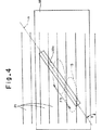
Fig.4およびFig.5は、遮光膜18のスリット18a周辺の詳細図であり、Fig.4には集光スポットの様子が示されており、Fig.5には、光磁気ディスク上にマークが形成される様子が示されている。
Fig.4およびFig.5には、光ディスク上に同心円状に多数設けられているトラック21の一部分が示されており、トラック21相互間の境界は平行線で示されている。光ディスクの大きさに対して、トラック21相互間の間隔やスリット18aの長さは十分に小さいので、スリット18a周辺に着目した場合にはトラック21は十分に直線的であると考えてよい。
Fig.4にはスリット18aの中心線mが一点鎖線で示されており、スリット18aは、トラック21に対して所定の角度αで交わるように設けられている。上述したように、スリット18a上には楕円状の集光スポットSが形成され、集光スポットSの長軸はトラック21に対して平行である。また、集光スポットSは、Fig.1およびFig.2に示すガルバノミラーが回動することによって回転走査されて、矢印F3が示すようにスリット18aに沿って移動し、これによりトラッキング動作が行われる。つまり、トラッキング動作時には遮光体を動かす必要がない。また、ここでは集光スポットSが楕円形であるため、集光スポットSの位置がスリット18aの幅方向に相対的にある程度ずれても、スリット18aを透過して光ディスク上に照射される光の光量は安定しており、即ち、集光スポットSの位置決めにはマージンがあるので、情報アクセスが安定している。
ここで、スリット18aとトラック21が交わる角度αについて考察する。
トラック21のトラックピッチをTpとし、Fig.3に示す集光レンズ17aおよびシリンドリカルレンズ17bからなる集光光学系の焦点距離をfとし、Fig.1およびFig.2に示すガルバノミラー12の最少回動によりレーザ光Lの進行方向が変更される最少変更角度をΔθとすると、トラックピッチTpがガルバノミラー12の最少回動による集光スポットSの移動量のいくつ分に相当するかを表すトラッキング誤差精度Cは、
C=Tp/(sinα・f・Δθ) ・・・(1)
なる関係式で表される。そして、このトラッキング誤差精度Cは少なくとも10以上の値であることが実用上不可欠であるため、
Tp/(sinα・f・Δθ)≧10
なる関係式を満たす角度αでスリット18aとトラック21が交わる必要がある。
また、現状における光磁気ディスクのトラックピッチTpは0.5μm程度であり、現状で一般的に求められるトラッキング誤差精度Cは150程度であり、通常のガルバノミラーによる最少変更角度Δθは1秒程度であり、通常の集光光学系の焦点距離fが1mm程度であることを考慮すると、式(1)から、スリット18aとトラック21が交わる角度αは45°以下であることが望ましいことがわかる。更に、角度αが5°以下であれば、トラックピッチTpが0.1μm程度で、かつ、トラッキング誤差精度Cが1000程度であるという極めて高いスペックも実現可能であるので、将来的な技術進歩にも十分に対応することができる。このように角度αを設定することにより、光学ヘッドを構成するガルバノミラーや集光レンズといった光学素子の設定精度の許容度が高くなる。
次に、スリット18aを透過した光によって光磁気ディスク上に形成される記録マークについて、Fig.5を参照しながら説明する。
光磁気ディスク上に照射された光は、レーザ光の1パルス毎に光磁気ディスク表面を加熱する。そして、集光スポットS内の光強度の分布や、スリット18aとトラック21との交差角度αや、光磁気ディスクの回転速度などが影響した結果として、楕円形領域21aが、記録磁場によって極性が反転可能な所定温度となる。ここで、Fig.3に示す平面コイル19によって記録磁場が発生されることにより、各楕円形領域21a内の極性は記録磁場の極性に応じた極性となる。また、楕円形領域21aの位置は、光磁気ディスクの回転に伴って各レーザパルス毎に少しずつずれていくので、記録磁場の極性が一定であると、その記録磁場の極性に応じた極性の領域が1パルス毎に延びていく。そして、記録磁場の極性が反転すると、その時点のレーザパルスによって所定温度になった楕円形領域21a内の極性も反転し、その結果、Fig.5に斜線を付して示したような三日月型の記録マーク21bが残されることとなる。
スリット18aを介して光磁気ディスクのトラック21上に照射される光は、上述したようにトラック幅方向のサイズがスリット18aによって物理的に小さくされているため、トラック21上に形成される三日月型の記録マーク21bのトラック幅方向のサイズも小さく、その分だけトラックピッチを狭くして記録密度を高めることができる。尚、三日月型の記録マーク21bとしては、縦横のサイズが互いに同程度のものが形成される。
上述した角度αを数度以内とし、トラック幅と矩形スリットの短辺の長さとをほぼ等しくするのが最も好ましく、トラック幅方向についてはスポットサイズが微細となる。また、スリットの長さ方向については光量のロスがなくてスポットサイズが微細ではないが、磁界変調によってマークサイズを短くすることできる。更に、スポットをガルバノミラーなどで粗く移動させても、トラック幅方向のトラッキングはきめ細やかに制御できる。
Fig.6は、本実施形態の光情報記憶装置の制御系等を表す概念構成図である。
半導体レーザ11から出射されコリメートレンズ13により平行光束にされた光は、偏光ビームスプリッタ40によって透過光と反射光に分離される。反射光は集光レンズ41によりフォトディテクタ42に集光され、半導体レーザの光量モニタや、オートパワーコントロールに用いられる。
偏光ビームスプリッタ40からの透過光は、ガルバノミラー12等を経由した後、照射光として、スライダ15に搭載された集光光学系により光磁気ディスク20上に集光される。
スライダ15には平面コイル19(Fig.3参照)が設けられており、この平面コイル19によって記憶磁界が発生される。光磁気ディスク20に記録する情報に応じた入力信号が入力系43から磁界変調駆動装置44に入力され、磁界変調駆動装置44から変調信号が出力される。この変調信号が平面コイル19に入力されると変調記録磁界が発生する。一方、半導体レーザ11は、レーザ光をパルス状に発しており、変調記録磁界のもとで光磁気ディスク20にレーザ光が照射されることにより、上述したような三日月型の記録マークが光磁気ディスク20上に形成される。このように記録マークが形成されることにより光磁気ディスク20に情報が記憶される。尚、ここでは、情報読み出しの際にはレーザ光のみが照射されて磁界は発生されないものとする。
偏光ビームスプリッタ40を透過して光磁気ディスク20上に照射された光は、光磁気ディスク20によって反射され、再び偏光ビームスプリッタ40に到達して更に反射された後、ビームスプリッタ45によって透過光と反射光に分割される。
ビームスプリッタ45により反射された光はフォーカシングエラー信号の検出に用いられる。フォーカシングエラー信号の検出方法としては、ナイフエッジ法、非点収差法、スポットサイズ検出法または臨界角法等が考えられ、どの方法で検出を行っても何ら問題ない。このFig.6には一例としてナイフエッジ法が示されており、ビームスプリッタ45により反射された光は、レンズ46、ナイフエッジ47を介して2分割フォトディテクタ48に到達する。2分割フォトディテクタ48からの信号は差動アンプ49によって検出され、フォーカシングエラー信号が得られる。このフォーカシングエラー信号がフォーカス制御系50に入力され、フィードバック信号が、フォーカス制御系50から、図示を省略したアクチュエータに入力される。このアクチュエータは、Fig.3に示す集光レンズを光磁気ディスク20に対して垂直な方向に駆動させるものである。
なお、ここではスライダ15が光磁気ディスク20の表面に対して浮上しているので、浮上量を適切な手段で安定させることによりフォーカス制御系50を省略することもできる。
上記ビームスプリッタ45を透過した光は、トラッキング制御と信号検出に用いられる。ビームスプリッタ45を透過した光は、ウォラストンプリズム51により偏光成分が分離され、レンズ52を経て2分割フォトディテクタ53に到達する。2分割フォトディテクタ53からの信号は、差動アンプ54により光磁気信号として検出されて検出系55に入力され、この検出系55によって、光磁気ディスク20に記憶されていた情報が得られる。
上述したようなトラックを光磁気ディスク20上に設ける方式としては、ここでは一例として、光磁気ディスク20上にプリグルーブを設けてトラックの境界として用いる方式が採用されているものとする。このようなプリグルーブを設ける方式では、光磁気ディスク20表面を平滑にすることができるので、スライダ15を光磁気ディスク20表面に十分に近接させることができる。
2分割フォトディテクタ53からの信号は、和算アンプ56によって足し合わされ、プリグルーブによって強度変調されたサンプルサーボ信号となってトラッキング制御系57に入力される。トラッキング制御系57は、サンプルサーボによるトラッキングエラー信号を検出し、このトラッキングエラー信号に基づいたフィードバック信号に従ってガルバノミラー12が回動する。その結果、Fig.4等で説明したようにトラッキング動作が行われる。また、ここでは、上述したシーク動作もトラッキング制御系57によって制御されており、更に、媒体保持部30による光磁気ディスク20の回転速度もシーク動作に応じて制御される。
なお、スリット18aとトラックとの交差角度αが小さくなると、スリット18aからの戻り光が弱くなる。この場合には、プリグルーブに替えて、トラックの位置情報を記録したピットパターンを用いたサンプルサーボ方式が有用である。このサンプルサーボ方式では、通常の再生信号を読み取るのと同様にサーボ信号を読み取る。
上記説明したような構成によって、大容量であり、かつデータ転送速度が高速な光情報記憶装置が実現される。
以下、本発明の光学ヘッドの他の実施形態について説明する。以下説明する実施形態の光学ヘッドは、スライダが異なる点を除いて、Fig.1およびFig.2に示す光学ヘッド10と同様の光学ヘッドであって、上記説明した光情報記憶装置の光学ヘッドとしてそのまま適用することができるものである。
Fig.7は、本発明の光学ヘッドの他の実施形態におけるスライダを示す斜視図であり、Fig.8は、そのスライダの断面図である。
このスライダ60には、集光レンズ61aとシリンドリカルレンズ61bが搭載されており、集光レンズ61aおよびシリンドリカルレンズ61bによって、本発明にいう集光手段の一例が構成されている。
また、このスライダ60には、本発明にいう遮光体の一例である遮光ブロック62が形成されており、遮光ブロック62にはスリット62aが設けられている。また、遮光ブロック62の周囲に沿って平面コイル63が設けられている。
遮光ブロック62はシリコン結晶で形成されており、シリンドリカルレンズ61bは、遮光ブロック62にフォトエッチング技術などによってスリット62aを設けた後、半導体材料を積層すること等によって形成される。但し、この半導体材料としては、赤外線を透過する性質を有するものが用いられ、光源としては、その赤外線を発する半導体レーザが用いられる。このような材料が用いられたスライダ60は、フォトエッチング技術などによって大量かつ安価に製造することができ、光学ヘッドや光情報記録装置のコストダウンを図ることができる。
このようなスライダ60により集光スポットが形成される様子は、Fig.3などを用いた説明と重複するので説明を省略する。
尚、本発明の光情報記憶装置や光学ヘッドでは、光源の短波長化および、シリンダレンズを形成するシリコンに屈折率の高いものを用いることにより、記録マークの微細化や高い光利用効率を実現することができる。また、光源としてLEDを用いることにより光源を十分に高出力化することができ、高速メモリが安価に実現できるよういう利点がある。
また、本発明にいう記録媒体は、光磁気ディスクに限定されるものではなく、レーザ光による補助が用いられる磁気ディスクであってもよい。このような磁気ディスクの場合には、情報再生は磁気ディスク用のGMRヘッドやスピンバルブヘッドが用いられて行われる。そして、これらのヘッドと、上述したスライダとを一体化して用いることができる。さらに、本発明にいう記録媒体は、光テープを用いた光カードであってもよく、この光カードは、直線状の平行トラックを有している。
【図面の簡単な説明】
Fig.1は光情報記憶装置の一実施形態に含まれる光学ヘッドの正面図である。
Fig.2は光情報記憶装置の一実施形態に含まれる光学ヘッドの側面図である。
Fig.3はスライダの詳細な構造を示す斜視図である。
Fig.4は遮光膜のスリット上の集光スポットの様子を示す図である。
Fig.5は光磁気ディスク上にマークが形成される様子を示す図である。
Fig.6は本実施形態の光情報記憶装置の制御系等を表す概念構成図である。
Fig.7は本発明の光学ヘッドの他の実施形態におけるスライダを示す斜視図である。
Fig.8は本発明の光学ヘッドの他の実施形態におけるスライダを示す断面図である。Technical field
The present invention relates to an optical information storage device that performs information access by irradiating light onto a recording medium surface, and an optical head used in such an information storage device.
Background art
Conventionally, optical disks such as CD, CD-ROM, CD-R, DVD, PD, and MO are known as media for storing voice, image information, characters, computer programs, and the like. There is also known an optical information storage device that forms a condensing spot by condensing laser light or the like using such an optical head, and accesses the optical disc using the condensing spot. Such an optical information storage device has attracted attention in terms of the portability of the recording medium, the large capacity, the small size, and the light weight. It is desired to dramatically improve the storage density of information.
The storage density of information by the optical information storage device as described above is higher as the focused spot size on the optical disk is smaller. Therefore, the development of short wavelength laser light sources and research on increasing the NA of the objective lens are being actively conducted. As a method for increasing the NA of the objective lens, the refractive index of an objective lens such as an oil immersion lens can be increased. There is known a method of realizing an objective lens having a numerical aperture exceeding 1 and about 1.4 by condensing light in a high medium. However, when the wavelength of the laser light source is shortened or the NA of the objective lens is increased, the size of the focused spot cannot be drastically reduced, and thus it is difficult to dramatically improve the storage density. In addition, a technique for physically forming a small focused spot using a pinhole has been proposed. However, with the technology using pinholes, the amount of light passing through the pinhole is small, the light utilization efficiency is 0.1% or less, and the positioning of the focused spot with respect to the pinhole is difficult. There is a problem that it is difficult to transfer and reproduce information. Further, at the time of tracking, it is necessary to translate the pinhole together with the condensing spot at a high speed, but it is difficult to realize a low-cost actuator that moves the pinhole at a high speed.
In contrast to these techniques, a magneto-optical recording technique based on a laser pulse magnetic field modulation method has been proposed as a technique for recording information with a mark length smaller than the focused spot size. However, in order to dramatically improve the storage density, it is indispensable to reduce the track pitch. However, there is a problem that the track pitch cannot be reduced by the magneto-optical recording technique as described above.
Disclosure of the invention
In view of the above circumstances, an object of the present invention is to provide an optical information storage device and an optical head capable of stable information access at a high storage density.
The first optical information storage device of the present invention that achieves the above object is an optical information storage for accessing information by irradiating light onto a recording medium surface having a track on which at least information is reproduced by being irradiated with light. In the device
A medium holding unit for holding the recording medium in a predetermined position;
An optical head for irradiating light onto the surface of the recording medium held by the medium holding unit,
The optical head
A light source that emits light;
A shading body provided with a slit;
A light-shielding body holding unit that holds the light-shielding body at a position close to or in contact with the surface of the recording medium such that the slit of the light-shielding body intersects the track at an angle of 45 ° or less;
Condensing means for condensing the light emitted from the light source onto the slit of the light shielding body;
And moving means for moving the light collected on the slit by the light collecting means along the slit.
In the first optical information storage device of the present invention, it is preferable that the holding unit holds the light shield so that the slit of the light shield intersects the track at an angle of 5 ° or less.
Further, the second optical information storage device of the present invention that achieves the above object is provided on the surface of a recording medium in which a plurality of linear tracks on which information is accessed by irradiation with light are provided at predetermined intervals. In an optical information storage device that accesses information by irradiating light,
A medium holding unit for holding the recording medium in a predetermined position;
An optical head for irradiating light onto the surface of the recording medium held by the medium holding unit,
The optical head
A light source that emits light;
A shading body provided with a slit;
A light-shielding body holding unit that holds the light-shielding body at a position close to or in contact with the surface of the recording medium such that the slit of the light-shielding body intersects the track at an angle of 45 ° or less;
Condensing means for condensing the light emitted from the light source onto the slit of the light shielding body;
Changing the incident angle of the light incident on the condensing means, and moving means for moving the light collected on the slit by the condensing means along the slit, and
The mutual distance Tp between the tracks, the focal length f of the light collecting means, the minimum change amount Δθ of the angle change by the moving means, and the angle α at which the slit intersects the track.
Tp / (sin α · f · Δθ) ≧ 10
It has the relationship which becomes.
Here, the track is not limited to those formed as physical grooves or the like as long as information is recorded in a linear form, and is formed only on a plane magnetically or optically. It may be.
In addition, the “slit” is a slit in an optical sense, and only needs to narrow the light beam only in a predetermined direction, and a portion that transmits light is filled with a transparent material such as glass. It may be.
Further, the light-shielding body holding unit may be a carriage that moves along a rail, or may be a swing arm that rotates around a predetermined viewpoint. In addition, these carriages and swing arms may hold a slider on which a light shield is mounted.
According to the first and second optical information storage devices of the present invention, the size of the focused spot in the slit width direction is physically reduced by the slit intersecting with the track at the angle described above, so that the track pitch can be reduced. It is possible to access information with high storage density. In particular, extremely high storage density can be realized by using in combination with the magneto-optical recording technique based on the laser pulse magnetic field modulation method. Also, in the longitudinal direction of the slit, there is no loss of the condensing spot and there is no loss of light utilization efficiency, so the light utilization efficiency is high, a sufficient amount of light can be irradiated to the recording medium, stable information access and high-speed data Transfer is possible. Furthermore, since the light condensed on the slit is moved along the slit by the moving means, the tracking accuracy becomes high in the direction orthogonal to the track, and fine tracking control can be performed.
In the first and second optical information storage devices of the present invention, it is preferable that the light condensing means of the optical head condenses light in an elliptical shape that is long in a direction parallel to the track of the recording medium. . By forming the condensing spot in such an ellipse shape, the positioning accuracy of the condensing spot with respect to the slit may be loose in the direction parallel to the track.
In addition, when the light collecting means of the optical head collects light in such an elliptical shape, the light collecting means is arranged so that the light-shielding body is oriented so that the bus line is oriented in a direction perpendicular to the track of the recording medium. It is desirable to have a cylindrical lens provided on the slit, and to collect light through the cylindrical lens.
The light source emits infrared rays,
The light-shielding body is made of silicon;
It is desirable that the condensing means includes a cylindrical lens made of a semiconductor that transmits the infrared rays.
The condensing means for forming the condensing spot in an elliptical shape can be realized with a simple structure by using a cylindrical lens. Further, the light shielding body and the cylindrical lens made of the above-described materials can be manufactured at low cost and in large quantities by using a photo etching technique or the like.
An optical head of the present invention that achieves the above object includes a light source that emits light,
A light shield provided with a slit for guiding light to the surface of the recording medium;
Condensing means for condensing the light emitted from the light source onto the slit of the light shielding body;
And moving means for moving the light collected on the slit by the light collecting means along the slit.
The optical head of the present invention is used in an optical storage device, and a slit provided in a light shield of the optical head and a track of a recording medium are held so that they intersect at an angle as described above, thereby stabilizing at a high storage density. Information access is possible.
In the optical head of the present invention, it is desirable that the light-shielding body is provided with a slit having a slit width that is half or less of the wavelength of light emitted from a light source, as the slit. By providing a slit having such a width, light called near-field light oozes out from the slit to form a fine spot, and information access at a remarkably high storage density can be performed.
Further, the optical head of the present invention may be provided with a coil along the slit of the light shielding body that is held at a position close to or in contact with the surface of the recording medium.
In order to generate a magnetic field necessary for magneto-optical recording by the laser pulse magnetic field modulation method on the surface of the recording medium, it is necessary to bring the coil close to the recording medium surface to about 10 μm. The coil can be sufficiently close to the surface of the recording medium.
As described above, according to the optical information storage device and the optical head of the present invention, stable information access with high storage density is possible.
BEST MODE FOR CARRYING OUT THE INVENTION
Hereinafter, one embodiment of the optical information storage device of the present invention including one embodiment of the optical head of the present invention will be described.
FIG. 1 is a front view of an optical head included in an embodiment of an optical information storage device. 2 is a side view of the optical head.
The
The laser beam L emitted from the
Further, the
Tracks for storing information are concentrically provided on the surface of the magneto-
FIG. 3 is a perspective view showing a detailed structure of the
The
FIG. 1 and FIG. The laser beam L reflected by the reflecting
Here, a magneto-optical recording technique based on a laser pulse magnetic field modulation method is employed, and recording is performed in which the laser light L modulated in a pulse shape at a predetermined time interval is irradiated and the polarity is inverted according to the recorded information. A magnetic field is generated by the
FIG. 4 and FIG. 5 is a detailed view around the
FIG. 4 and FIG. 5 shows a part of a plurality of
FIG. 4, a center line m of the
Here, the angle α at which the
The track pitch of the
C = Tp / (sin α · f · Δθ) (1)
It is expressed by the following relational expression. And since it is indispensable practically that this tracking error accuracy C is a value of at least 10 or more,
Tp / (sin α · f · Δθ) ≧ 10
The
Further, the track pitch Tp of the present magneto-optical disk is about 0.5 μm, the tracking error accuracy C generally required at present is about 150, and the minimum change angle Δθ by a normal galvanometer mirror is about 1 second. In view of the fact that the focal length f of a normal condensing optical system is about 1 mm, it can be seen from the equation (1) that the angle α at which the
Next, with respect to the recording mark formed on the magneto-optical disk by the light transmitted through the
The light irradiated on the magneto-optical disk heats the surface of the magneto-optical disk for each pulse of the laser beam. As a result of the influence of the light intensity distribution in the condensing spot S, the crossing angle α between the
The light irradiated onto the
It is most preferable that the angle α is within a few degrees, and the track width and the length of the short side of the rectangular slit are substantially equal, and the spot size is fine in the track width direction. Further, although there is no loss of light quantity and the spot size is not fine in the slit length direction, the mark size can be shortened by magnetic field modulation. Furthermore, even if the spot is roughly moved by a galvanometer mirror or the like, tracking in the track width direction can be finely controlled.
FIG. 6 is a conceptual configuration diagram showing a control system and the like of the optical information storage device of the present embodiment.
The light emitted from the
The transmitted light from the
The
The light transmitted through the
The light reflected by the
Here, since the
The light transmitted through the
As a method of providing the tracks as described above on the magneto-
The signals from the two-divided
When the crossing angle α between the
With the configuration as described above, an optical information storage device having a large capacity and a high data transfer rate is realized.
Hereinafter, other embodiments of the optical head of the present invention will be described. The optical head according to the embodiment described below is the same as the optical head shown in FIG. 1 and FIG. The optical head is the same as the
FIG. 7 is a perspective view showing a slider in another embodiment of the optical head of the present invention, FIG. 8 is a cross-sectional view of the slider.
The
Further, the
The
The manner in which the condensed spot is formed by such a
In the optical information storage device and optical head of the present invention, the recording mark is miniaturized and high light utilization efficiency is realized by shortening the wavelength of the light source and using silicon having a high refractive index for forming the cylinder lens. can do. Further, by using an LED as the light source, the output of the light source can be sufficiently increased, and there is an advantage that a high-speed memory can be realized at low cost.
In addition, the recording medium referred to in the present invention is not limited to a magneto-optical disk, and may be a magnetic disk using assistance by a laser beam. In such a magnetic disk, information reproduction is performed using a GMR head or a spin valve head for the magnetic disk. These heads and the slider described above can be used in an integrated manner. Furthermore, the recording medium referred to in the present invention may be an optical card using an optical tape, and this optical card has linear parallel tracks.
[Brief description of the drawings]
FIG. 1 is a front view of an optical head included in an embodiment of an optical information storage device.
FIG. 2 is a side view of an optical head included in an embodiment of the optical information storage device.
FIG. 3 is a perspective view showing a detailed structure of the slider.
FIG. 4 is a view showing a state of a condensing spot on the slit of the light shielding film.
FIG. FIG. 5 is a diagram showing how marks are formed on the magneto-optical disk.
FIG. 6 is a conceptual configuration diagram showing a control system and the like of the optical information storage device of the present embodiment.
FIG. 7 is a perspective view showing a slider in another embodiment of the optical head of the present invention.
FIG. 8 is a cross-sectional view showing a slider in another embodiment of the optical head of the present invention.
Claims (7)
前記記録媒体を所定の位置に保持する媒体保持部と、
前記媒体保持部が保持している記録媒体表面に光を照射する光学ヘッドとを備え、
前記光学ヘッドが、
光を発する光源と、
スリットが設けられた遮光体と、
前記遮光体を、該遮光体のスリットが前記トラックに対して45°以下の角度αで交わるように、前記記録媒体表面に近接しあるいは接触した位置に保持する遮光体保持部と、
前記光源から発せられた光を前記遮光体のスリット上に集光する集光手段と、
前記集光手段によってスリット上に集光された光を該スリットに沿って移動させる移動手段とを具備し、
前記遮光体のスリットの寸法は、スリットの長手方向の長さ×sinαがトラック幅より長く、スリットの幅が、前記集光手段によって集光される光のスポットサイズよりも狭いことを特徴とする光情報記憶装置。In an optical information storage device that reproduces at least information by irradiating light on the surface of a recording medium having a track on which information is reproduced at least by irradiation of light,
A medium holding unit for holding the recording medium in a predetermined position;
An optical head for irradiating light onto the surface of the recording medium held by the medium holding unit,
The optical head is
A light source that emits light;
A shading body provided with a slit;
A light-shielding body holding unit that holds the light-shielding body at a position close to or in contact with the surface of the recording medium such that the slit of the light-shielding body intersects the track at an angle α of 45 ° or less;
Condensing means for condensing the light emitted from the light source onto the slit of the light shielding body;
Moving means for moving the light collected on the slit by the light collecting means along the slit ;
The dimension of the slit of the light shielding body is characterized in that the length in the longitudinal direction of the slit × sin α is longer than the track width, and the width of the slit is narrower than the spot size of the light collected by the light collecting means. Optical information storage device.
前記記録媒体を所定の位置に保持する媒体保持部と、
前記媒体保持部が保持している記録媒体表面に光を照射する光学ヘッドとを備え、
前記光学ヘッドが、
光を発する光源と、
スリットが設けられた遮光体と、
前記遮光体を、該遮光体のスリットが前記トラックに対して45°以下の角度αで交わるように、前記記録媒体表面に近接しあるいは接触した位置に保持する遮光体保持部と、
前記光源が発した光を前記遮光体のスリット上に集光する集光手段と、
前記集光手段に入射する光の入射角度を変えて、該集光手段によってスリット上に集光された光を該スリットに沿って移動させる移動手段とを具備し、
前記遮光体のスリットの寸法は、スリットの長手方向の長さ×sinαがトラック幅より長く、スリットの幅が、前記集光手段によって集光される光のスポットサイズよりも狭く、かつ、
前記トラックの相互間隔Tpと、前記集光手段の焦点距離fと、前記移動手段による角度変更の最小変更量Δθと、前記トラックに対して前記スリットが交わる角度αとが
Tp/(sinα・f・Δθ)≧10
なる関係を有するものであることを特徴とする光情報記憶装置。In an optical information storage device that reproduces at least information by irradiating light on the surface of a recording medium in which tracks on which at least information is reproduced by light irradiation are provided at predetermined intervals,
A medium holding unit for holding the recording medium in a predetermined position;
An optical head for irradiating light onto the surface of the recording medium held by the medium holding unit,
The optical head is
A light source that emits light;
A shading body provided with a slit;
A light-shielding body holding unit that holds the light-shielding body at a position close to or in contact with the surface of the recording medium such that the slit of the light-shielding body intersects the track at an angle α of 45 ° or less;
Condensing means for condensing the light emitted from the light source onto the slit of the light shielding body;
Changing the incident angle of the light incident on the light collecting means, and moving means for moving the light condensed on the slit by the light collecting means along the slit,
The dimension of the slit of the light shielding body is such that the length in the longitudinal direction of the slit × sin α is longer than the track width, the width of the slit is narrower than the spot size of the light collected by the light collecting means, and
The mutual distance Tp between the tracks, the focal length f of the light collecting means, the minimum change amount Δθ of the angle change by the moving means, and the angle α at which the slit intersects the track Tp / (sin α · f・ Δθ) ≧ 10
An optical information storage device characterized by having the following relationship:
記録媒体表面に対して光を導くスリットが設けられた遮光体と、
光が照射されることによって情報が少なくとも再生されるトラックが所定間隔で設けられた記録媒体のトラックに対して前記遮光体のスリットが45°以下の角度αで交わるように該遮光体を、前記記録媒体表面に近接しあるいは接触した位置に保持する遮光体保持部と、
前記光源から発せられた光を前記遮光体のスリット上に集光する集光手段と、
前記集光手段によってスリット上に集光された光を該スリットに沿って移動させる移動手段とを具備し、
前記遮光体のスリットの寸法は、スリットの長手方向の長さ×sinαがトラック幅より長く、スリットの幅が、前記集光手段によって集光される光のスポットサイズよりも狭いことを特徴とする光学ヘッド。A light source that emits light;
A light shield provided with a slit for guiding light to the surface of the recording medium;
The light shielding body is arranged so that the slit of the light shielding body intersects at an angle α of 45 ° or less with respect to the track of the recording medium in which at least tracks on which information is reproduced by light irradiation are provided at predetermined intervals. A light-shielding body holding unit that holds the recording medium surface close to or in contact with the surface,
Condensing means for condensing the light emitted from the light source onto the slit of the light shielding body;
Moving means for moving the light collected on the slit by the light collecting means along the slit ;
The dimension of the slit of the light shielding body is characterized in that the length in the longitudinal direction of the slit × sin α is longer than the track width, and the width of the slit is narrower than the spot size of the light collected by the light collecting means. Optical head.
Applications Claiming Priority (1)
| Application Number | Priority Date | Filing Date | Title |
|---|---|---|---|
| PCT/JP1999/006284 WO2001035399A1 (en) | 1999-11-11 | 1999-11-11 | Optical information storage and optical head |
Publications (1)
| Publication Number | Publication Date |
|---|---|
| JP4392149B2 true JP4392149B2 (en) | 2009-12-24 |
Family
ID=14237255
Family Applications (1)
| Application Number | Title | Priority Date | Filing Date |
|---|---|---|---|
| JP2001537053A Expired - Fee Related JP4392149B2 (en) | 1999-11-11 | 1999-11-11 | Optical information storage device and optical head |
Country Status (5)
| Country | Link |
|---|---|
| US (1) | US6563781B2 (en) |
| EP (1) | EP1229525B1 (en) |
| JP (1) | JP4392149B2 (en) |
| DE (1) | DE69933708T2 (en) |
| WO (1) | WO2001035399A1 (en) |
Families Citing this family (6)
| Publication number | Priority date | Publication date | Assignee | Title |
|---|---|---|---|---|
| JP2002050001A (en) * | 2000-05-23 | 2002-02-15 | Sharp Corp | Information recording and reproducing head, information recording and reproducing device, tracking device and information recording medium |
| US6735005B2 (en) * | 2001-11-09 | 2004-05-11 | Tokyo Seimitso (Israel) Ltd. | Cartesian scanning system |
| KR100792593B1 (en) * | 2005-10-12 | 2008-01-09 | 한국정보통신대학교 산학협력단 | Method for formating single pulse pattern by using a ultrashort pulse laser and its system |
| CA2904893C (en) * | 2013-03-13 | 2021-11-16 | Optimedica Corporation | Free floating patient interface for laser surgery system |
| AU2014242096B2 (en) | 2013-03-13 | 2018-06-28 | Amo Development, Llc | Laser eye surgery system |
| US9508380B2 (en) | 2013-10-29 | 2016-11-29 | Sony Corporation Of America | Enclosure for reading an optical medium at an input port |
Family Cites Families (13)
| Publication number | Priority date | Publication date | Assignee | Title |
|---|---|---|---|---|
| JPS57108811A (en) * | 1980-12-26 | 1982-07-07 | Hitachi Ltd | Optical focus position detector |
| US4742219A (en) * | 1981-09-17 | 1988-05-03 | Tokyo Shibaura Denki Kabushiki Kaisha | Apparatus for detecting the focusing state and positional accuracy of a light beam directed onto an optical disk tracking guide in an optical read/write system |
| JPS62112245A (en) * | 1985-11-12 | 1987-05-23 | Olympus Optical Co Ltd | Recording and reproducing device for optical recording disk |
| JPS6363137A (en) * | 1986-09-02 | 1988-03-19 | Seiko Epson Corp | Optical head |
| JPH0619845B2 (en) | 1986-09-26 | 1994-03-16 | ティアツク株式会社 | Disk fluctuation state detection device |
| JPH01232581A (en) | 1988-03-11 | 1989-09-18 | Hitachi Ltd | Position detecting device |
| US5125750A (en) | 1991-03-14 | 1992-06-30 | The Board Of Trustees Of The Leland Stanford Junior University | Optical recording system employing a solid immersion lens |
| JP3019181B2 (en) | 1993-12-27 | 2000-03-13 | 日本電気株式会社 | Optical head servo signal detection device |
| US5600620A (en) * | 1994-11-08 | 1997-02-04 | Nec Corporation | Optical head apparatus having means to eliminate noise caused by side-lobes |
| EP1150281B1 (en) * | 1995-02-02 | 2004-05-12 | Pioneer Electronic Corporation | Optical pickup apparatus and identification apparatus for identifying the type of optical record medium |
| JP3071141B2 (en) | 1995-06-12 | 2000-07-31 | 三洋電機株式会社 | Optical recording or optical reproducing device |
| JPH10162443A (en) | 1996-12-02 | 1998-06-19 | Sanyo Electric Co Ltd | Information reproducing device |
| JPH10320826A (en) | 1997-03-14 | 1998-12-04 | Sanyo Electric Co Ltd | Optical pickup device and optical recording medium driving device using the same |
-
1999
- 1999-11-11 WO PCT/JP1999/006284 patent/WO2001035399A1/en active IP Right Grant
- 1999-11-11 JP JP2001537053A patent/JP4392149B2/en not_active Expired - Fee Related
- 1999-11-11 DE DE69933708T patent/DE69933708T2/en not_active Expired - Lifetime
- 1999-11-11 EP EP99974164A patent/EP1229525B1/en not_active Expired - Lifetime
-
2002
- 2002-03-14 US US10/097,317 patent/US6563781B2/en not_active Expired - Fee Related
Also Published As
| Publication number | Publication date |
|---|---|
| EP1229525A1 (en) | 2002-08-07 |
| DE69933708T2 (en) | 2007-02-22 |
| DE69933708D1 (en) | 2006-11-30 |
| WO2001035399A1 (en) | 2001-05-17 |
| EP1229525A4 (en) | 2005-10-19 |
| US20020093903A1 (en) | 2002-07-18 |
| US6563781B2 (en) | 2003-05-13 |
| EP1229525B1 (en) | 2006-10-18 |
Similar Documents
| Publication | Publication Date | Title |
|---|---|---|
| JPH03102647A (en) | Optical head | |
| JP2000331302A (en) | Recording/reproducing head, recording/reproducing disk device, and manufacture of magnetic sensor | |
| US6992968B2 (en) | Optical head and disk unit | |
| KR20000029090A (en) | Magneto-optical head device having integrated auxiliary lens and magnetic reproducing haed and recording and reproducing device using magneto-optical head device | |
| JP4392149B2 (en) | Optical information storage device and optical head | |
| JP2000242963A (en) | Optical information storage device and optical head | |
| JP2001256601A (en) | Composite magnetic head device, information recoridng/ reproducing device using the same, and recording medium | |
| JP3782916B2 (en) | Optical information storage device and optical element | |
| JP2794876B2 (en) | Flying magnetic head position controller | |
| JP3773681B2 (en) | Optical head, optical component, and optical storage device | |
| JP2790705B2 (en) | Optical information writing / reading device | |
| KR100392255B1 (en) | Near-field optical data storage head minimized by using SIL | |
| JPH11213420A (en) | Information recording and reproducing head, and information recording and reproducing device | |
| JPS6316429A (en) | Optical head device for information recording medium | |
| JP2929463B2 (en) | Magneto-optical disk drive | |
| JP2000099970A (en) | Optical disk device | |
| JP3580040B2 (en) | Optical pickup device and disc player device | |
| JP2797676B2 (en) | Magneto-optical disk drive | |
| JP2792267B2 (en) | Light head | |
| JP2000149304A (en) | Optical disk device and optical pickup as well as hemispherical lens used for the same and its production | |
| JPH04126318U (en) | optical head device | |
| JP2001307348A (en) | Near-field optical head | |
| JPH0354738A (en) | Optical recording and reproducing device | |
| JP2000339769A (en) | Information recording medium and information recording and reproducing device | |
| JP2003109242A (en) | Proximity field light probe unit and information recording/reproducing device |
Legal Events
| Date | Code | Title | Description |
|---|---|---|---|
| A621 | Written request for application examination |
Free format text: JAPANESE INTERMEDIATE CODE: A621 Effective date: 20060810 |
|
| A131 | Notification of reasons for refusal |
Free format text: JAPANESE INTERMEDIATE CODE: A131 Effective date: 20090106 |
|
| A521 | Written amendment |
Free format text: JAPANESE INTERMEDIATE CODE: A523 Effective date: 20090309 |
|
| A131 | Notification of reasons for refusal |
Free format text: JAPANESE INTERMEDIATE CODE: A131 Effective date: 20090707 |
|
| A521 | Written amendment |
Free format text: JAPANESE INTERMEDIATE CODE: A523 Effective date: 20090904 |
|
| TRDD | Decision of grant or rejection written | ||
| A01 | Written decision to grant a patent or to grant a registration (utility model) |
Free format text: JAPANESE INTERMEDIATE CODE: A01 Effective date: 20091006 |
|
| A01 | Written decision to grant a patent or to grant a registration (utility model) |
Free format text: JAPANESE INTERMEDIATE CODE: A01 |
|
| A61 | First payment of annual fees (during grant procedure) |
Free format text: JAPANESE INTERMEDIATE CODE: A61 Effective date: 20091009 |
|
| FPAY | Renewal fee payment (event date is renewal date of database) |
Free format text: PAYMENT UNTIL: 20121016 Year of fee payment: 3 |
|
| R150 | Certificate of patent or registration of utility model |
Free format text: JAPANESE INTERMEDIATE CODE: R150 |
|
| FPAY | Renewal fee payment (event date is renewal date of database) |
Free format text: PAYMENT UNTIL: 20121016 Year of fee payment: 3 |
|
| FPAY | Renewal fee payment (event date is renewal date of database) |
Free format text: PAYMENT UNTIL: 20131016 Year of fee payment: 4 |
|
| LAPS | Cancellation because of no payment of annual fees |