EP1229525B1 - Optical head and optical information storage device - Google Patents
Optical head and optical information storage device Download PDFInfo
- Publication number
- EP1229525B1 EP1229525B1 EP99974164A EP99974164A EP1229525B1 EP 1229525 B1 EP1229525 B1 EP 1229525B1 EP 99974164 A EP99974164 A EP 99974164A EP 99974164 A EP99974164 A EP 99974164A EP 1229525 B1 EP1229525 B1 EP 1229525B1
- Authority
- EP
- European Patent Office
- Prior art keywords
- light
- slit
- recording medium
- shielding body
- optical
- Prior art date
- Legal status (The legal status is an assumption and is not a legal conclusion. Google has not performed a legal analysis and makes no representation as to the accuracy of the status listed.)
- Expired - Lifetime
Links
Images


Classifications
-
- G—PHYSICS
- G11—INFORMATION STORAGE
- G11B—INFORMATION STORAGE BASED ON RELATIVE MOVEMENT BETWEEN RECORD CARRIER AND TRANSDUCER
- G11B7/00—Recording or reproducing by optical means, e.g. recording using a thermal beam of optical radiation by modifying optical properties or the physical structure, reproducing using an optical beam at lower power by sensing optical properties; Record carriers therefor
- G11B7/08—Disposition or mounting of heads or light sources relatively to record carriers
- G11B7/085—Disposition or mounting of heads or light sources relatively to record carriers with provision for moving the light beam into, or out of, its operative position or across tracks, otherwise than during the transducing operation, e.g. for adjustment or preliminary positioning or track change or selection
- G11B7/08547—Arrangements for positioning the light beam only without moving the head, e.g. using static electro-optical elements
- G11B7/08564—Arrangements for positioning the light beam only without moving the head, e.g. using static electro-optical elements using galvanomirrors
-
- G—PHYSICS
- G11—INFORMATION STORAGE
- G11B—INFORMATION STORAGE BASED ON RELATIVE MOVEMENT BETWEEN RECORD CARRIER AND TRANSDUCER
- G11B11/00—Recording on or reproducing from the same record carrier wherein for these two operations the methods are covered by different main groups of groups G11B3/00 - G11B7/00 or by different subgroups of group G11B9/00; Record carriers therefor
- G11B11/10—Recording on or reproducing from the same record carrier wherein for these two operations the methods are covered by different main groups of groups G11B3/00 - G11B7/00 or by different subgroups of group G11B9/00; Record carriers therefor using recording by magnetic means or other means for magnetisation or demagnetisation of a record carrier, e.g. light induced spin magnetisation; Demagnetisation by thermal or stress means in the presence or not of an orienting magnetic field
- G11B11/105—Recording on or reproducing from the same record carrier wherein for these two operations the methods are covered by different main groups of groups G11B3/00 - G11B7/00 or by different subgroups of group G11B9/00; Record carriers therefor using recording by magnetic means or other means for magnetisation or demagnetisation of a record carrier, e.g. light induced spin magnetisation; Demagnetisation by thermal or stress means in the presence or not of an orienting magnetic field using a beam of light or a magnetic field for recording by change of magnetisation and a beam of light for reproducing, i.e. magneto-optical, e.g. light-induced thermomagnetic recording, spin magnetisation recording, Kerr or Faraday effect reproducing
- G11B11/10532—Heads
- G11B11/10534—Heads for recording by magnetising, demagnetising or transfer of magnetisation, by radiation, e.g. for thermomagnetic recording
- G11B11/10536—Heads for recording by magnetising, demagnetising or transfer of magnetisation, by radiation, e.g. for thermomagnetic recording using thermic beams, e.g. lasers
-
- G—PHYSICS
- G11—INFORMATION STORAGE
- G11B—INFORMATION STORAGE BASED ON RELATIVE MOVEMENT BETWEEN RECORD CARRIER AND TRANSDUCER
- G11B11/00—Recording on or reproducing from the same record carrier wherein for these two operations the methods are covered by different main groups of groups G11B3/00 - G11B7/00 or by different subgroups of group G11B9/00; Record carriers therefor
- G11B11/10—Recording on or reproducing from the same record carrier wherein for these two operations the methods are covered by different main groups of groups G11B3/00 - G11B7/00 or by different subgroups of group G11B9/00; Record carriers therefor using recording by magnetic means or other means for magnetisation or demagnetisation of a record carrier, e.g. light induced spin magnetisation; Demagnetisation by thermal or stress means in the presence or not of an orienting magnetic field
- G11B11/105—Recording on or reproducing from the same record carrier wherein for these two operations the methods are covered by different main groups of groups G11B3/00 - G11B7/00 or by different subgroups of group G11B9/00; Record carriers therefor using recording by magnetic means or other means for magnetisation or demagnetisation of a record carrier, e.g. light induced spin magnetisation; Demagnetisation by thermal or stress means in the presence or not of an orienting magnetic field using a beam of light or a magnetic field for recording by change of magnetisation and a beam of light for reproducing, i.e. magneto-optical, e.g. light-induced thermomagnetic recording, spin magnetisation recording, Kerr or Faraday effect reproducing
- G11B11/10532—Heads
- G11B11/10541—Heads for reproducing
- G11B11/10543—Heads for reproducing using optical beam of radiation
-
- G—PHYSICS
- G11—INFORMATION STORAGE
- G11B—INFORMATION STORAGE BASED ON RELATIVE MOVEMENT BETWEEN RECORD CARRIER AND TRANSDUCER
- G11B11/00—Recording on or reproducing from the same record carrier wherein for these two operations the methods are covered by different main groups of groups G11B3/00 - G11B7/00 or by different subgroups of group G11B9/00; Record carriers therefor
- G11B11/10—Recording on or reproducing from the same record carrier wherein for these two operations the methods are covered by different main groups of groups G11B3/00 - G11B7/00 or by different subgroups of group G11B9/00; Record carriers therefor using recording by magnetic means or other means for magnetisation or demagnetisation of a record carrier, e.g. light induced spin magnetisation; Demagnetisation by thermal or stress means in the presence or not of an orienting magnetic field
- G11B11/105—Recording on or reproducing from the same record carrier wherein for these two operations the methods are covered by different main groups of groups G11B3/00 - G11B7/00 or by different subgroups of group G11B9/00; Record carriers therefor using recording by magnetic means or other means for magnetisation or demagnetisation of a record carrier, e.g. light induced spin magnetisation; Demagnetisation by thermal or stress means in the presence or not of an orienting magnetic field using a beam of light or a magnetic field for recording by change of magnetisation and a beam of light for reproducing, i.e. magneto-optical, e.g. light-induced thermomagnetic recording, spin magnetisation recording, Kerr or Faraday effect reproducing
- G11B11/1055—Disposition or mounting of transducers relative to record carriers
- G11B11/10552—Arrangements of transducers relative to each other, e.g. coupled heads, optical and magnetic head on the same base
- G11B11/10554—Arrangements of transducers relative to each other, e.g. coupled heads, optical and magnetic head on the same base the transducers being disposed on the same side of the carrier
-
- G—PHYSICS
- G11—INFORMATION STORAGE
- G11B—INFORMATION STORAGE BASED ON RELATIVE MOVEMENT BETWEEN RECORD CARRIER AND TRANSDUCER
- G11B11/00—Recording on or reproducing from the same record carrier wherein for these two operations the methods are covered by different main groups of groups G11B3/00 - G11B7/00 or by different subgroups of group G11B9/00; Record carriers therefor
- G11B11/10—Recording on or reproducing from the same record carrier wherein for these two operations the methods are covered by different main groups of groups G11B3/00 - G11B7/00 or by different subgroups of group G11B9/00; Record carriers therefor using recording by magnetic means or other means for magnetisation or demagnetisation of a record carrier, e.g. light induced spin magnetisation; Demagnetisation by thermal or stress means in the presence or not of an orienting magnetic field
- G11B11/105—Recording on or reproducing from the same record carrier wherein for these two operations the methods are covered by different main groups of groups G11B3/00 - G11B7/00 or by different subgroups of group G11B9/00; Record carriers therefor using recording by magnetic means or other means for magnetisation or demagnetisation of a record carrier, e.g. light induced spin magnetisation; Demagnetisation by thermal or stress means in the presence or not of an orienting magnetic field using a beam of light or a magnetic field for recording by change of magnetisation and a beam of light for reproducing, i.e. magneto-optical, e.g. light-induced thermomagnetic recording, spin magnetisation recording, Kerr or Faraday effect reproducing
- G11B11/1055—Disposition or mounting of transducers relative to record carriers
- G11B11/1058—Flying heads
-
- G—PHYSICS
- G11—INFORMATION STORAGE
- G11B—INFORMATION STORAGE BASED ON RELATIVE MOVEMENT BETWEEN RECORD CARRIER AND TRANSDUCER
- G11B7/00—Recording or reproducing by optical means, e.g. recording using a thermal beam of optical radiation by modifying optical properties or the physical structure, reproducing using an optical beam at lower power by sensing optical properties; Record carriers therefor
- G11B7/12—Heads, e.g. forming of the optical beam spot or modulation of the optical beam
- G11B7/122—Flying-type heads, e.g. analogous to Winchester type in magnetic recording
-
- G—PHYSICS
- G11—INFORMATION STORAGE
- G11B—INFORMATION STORAGE BASED ON RELATIVE MOVEMENT BETWEEN RECORD CARRIER AND TRANSDUCER
- G11B7/00—Recording or reproducing by optical means, e.g. recording using a thermal beam of optical radiation by modifying optical properties or the physical structure, reproducing using an optical beam at lower power by sensing optical properties; Record carriers therefor
- G11B7/12—Heads, e.g. forming of the optical beam spot or modulation of the optical beam
- G11B7/135—Means for guiding the beam from the source to the record carrier or from the record carrier to the detector
- G11B7/1362—Mirrors
-
- G—PHYSICS
- G11—INFORMATION STORAGE
- G11B—INFORMATION STORAGE BASED ON RELATIVE MOVEMENT BETWEEN RECORD CARRIER AND TRANSDUCER
- G11B7/00—Recording or reproducing by optical means, e.g. recording using a thermal beam of optical radiation by modifying optical properties or the physical structure, reproducing using an optical beam at lower power by sensing optical properties; Record carriers therefor
- G11B7/12—Heads, e.g. forming of the optical beam spot or modulation of the optical beam
- G11B7/135—Means for guiding the beam from the source to the record carrier or from the record carrier to the detector
- G11B7/1372—Lenses
- G11B7/1374—Objective lenses
-
- G—PHYSICS
- G11—INFORMATION STORAGE
- G11B—INFORMATION STORAGE BASED ON RELATIVE MOVEMENT BETWEEN RECORD CARRIER AND TRANSDUCER
- G11B7/00—Recording or reproducing by optical means, e.g. recording using a thermal beam of optical radiation by modifying optical properties or the physical structure, reproducing using an optical beam at lower power by sensing optical properties; Record carriers therefor
- G11B7/12—Heads, e.g. forming of the optical beam spot or modulation of the optical beam
- G11B7/135—Means for guiding the beam from the source to the record carrier or from the record carrier to the detector
- G11B7/1387—Means for guiding the beam from the source to the record carrier or from the record carrier to the detector using the near-field effect
-
- G—PHYSICS
- G11—INFORMATION STORAGE
- G11B—INFORMATION STORAGE BASED ON RELATIVE MOVEMENT BETWEEN RECORD CARRIER AND TRANSDUCER
- G11B5/00—Recording by magnetisation or demagnetisation of a record carrier; Reproducing by magnetic means; Record carriers therefor
- G11B2005/0002—Special dispositions or recording techniques
- G11B2005/0005—Arrangements, methods or circuits
- G11B2005/0021—Thermally assisted recording using an auxiliary energy source for heating the recording layer locally to assist the magnetization reversal
-
- G—PHYSICS
- G11—INFORMATION STORAGE
- G11B—INFORMATION STORAGE BASED ON RELATIVE MOVEMENT BETWEEN RECORD CARRIER AND TRANSDUCER
- G11B7/00—Recording or reproducing by optical means, e.g. recording using a thermal beam of optical radiation by modifying optical properties or the physical structure, reproducing using an optical beam at lower power by sensing optical properties; Record carriers therefor
- G11B7/12—Heads, e.g. forming of the optical beam spot or modulation of the optical beam
- G11B7/135—Means for guiding the beam from the source to the record carrier or from the record carrier to the detector
- G11B7/1372—Lenses
- G11B2007/13727—Compound lenses, i.e. two or more lenses co-operating to perform a function, e.g. compound objective lens including a solid immersion lens, positive and negative lenses either bonded together or with adjustable spacing
Definitions
- the present invention relates to an optical information storage device for accessing information by irradiating a light on a surface of a recording medium, and an optical head used for such an information storage device.
- an optical disk such as a CD, a CD-ROM, a CD-R, a DVD, a PD or an MO
- An optical information storage device which forms a condensing spot by using the optical head to condense a laser beam or the like on such an optical disk, and accesses the optical disk by using the condensing spot.
- Such an optical information storage device is now a focus of attention because of portability of a recording medium, a large capacity and a light weight. With achievement of higher performance of a computer in recent years, there is a demand for a great increase in an information recording density by such an optical information storage device.
- the information recording density by the above-described optical information storage device is higher as a size of the condensing spot on the optical disk is smaller.
- developments of a shorter wavelength laser beam source, and studies of a higher NA of an objective lens have been actively conducted.
- a method for realizing an objective lens which has a numerical aperture set to exceed 1 and reach about 1.4 by condensing a light in a medium of a high refractive index, as in the case of an oil immersion lens of an optical microscope.
- the size of the condensing spot cannot be greatly reduced by the shorter wavelength of the laser beam source or the higher NA of the objective lens, and thus it is difficult to greatly increase the recording density.
- a magneto-optical recording technology based on a laser pulse magnetic field modulation system which records information by a mark length smaller than the size of the condensing spot.
- narrowing of a track pitch is essential.
- US 5600620 discloses an optical head apparatus including a light source, an optical modulation unit, an objective lens, a reflected beam condensing unit, and a photodetection unit.
- the light source emits a light beam.
- the optical modulation unit modulates one of a light intensity and a phase in a section of the light beam from the light source and adjusts a generation position of a side lobe light beam of the light beam.
- the optical modulation unit has at least a first strip-like light-shielding area inclined by a first predetermined angle with respect to a vertical axis in the section of the light beam.
- the objective lens focuses the light beam from the optical modulation unit to form a small spot on a recording medium.
- the reflected beam condensing unit condenses a reflected beam from the small spot on the recording medium.
- the photodetection unit detects the reflected beam from the reflected beam condensing unit to reproduce information.
- the present invention has been developed to solve the foregoing problems, and an object of the present invention is to provide an optical information storage device capable of performing stable information accessing at a high recording density, and an optical head.
- an optical head comprising:
- Such an optical head can be used for an optical storage device, and the slit provided in the light shielding body of the optical head intersects the track of the recording medium by the foregoing angle, and thus, it is possible to perform stable information accessing a high recording density.
- the slit provided in the light shielding body has a width set equal to or less than 1/2 of a wavelength of the light emitted from the light source. Because of the slit provided to have such a width, a light called near light is oozed out from the slit to form a fine spot, making it possible to access information at a much higher recording density.
- a coil may be provided along the slit of the light shielding body held in the position close to/in contact with the surface of the recording surface.
- the coil To generate a magnetic field necessary for magneto-optical recording by a laser pulse magnetic field modulation system on the surface of the recording medium, the coil must be brought close to about 10 ⁇ m from the surface of the recording medium.
- the foregoing coil can be brought sufficiently close to the surface of the recording medium.
- an optical information storage device for at least performing information reproducing by irradiating a light on a surface of a recording medium, the recording medium having a track irradiated with the light to at least reproduce information, comprising: a medium holding section for holding the recording medium in a predetermined position; and an optical head, embodying the aforesaid first aspect of the present invention, for irradiating the light on the surface of the recording medium held by said medium holding section, wherein said optical head further includes a light shielding body holding section for holding the light shielding body in a position close to/in contact with the surface of the recording medium such that the slit of the light shielding body intersects the track by an angle of 45° or lower.
- the holding section holds the light shielding body such that the slit of the light shielding body intersects the track by an angle of 5° or lower.
- an optical information storage device for at least performing information reproducing by irradiating a light on a surface of a recording medium, the recording medium having tracks provided at predetermined intervals and irradiated with the light to at least reproduce information, comprising: a medium holding section for holding the recording medium in a predetermined position; and an optical head, embodying the aforesaid first aspect of the invention, for irradiating the light on the surface of the recording medium held by said medium holding section, wherein: said optical head further includes a light shielding body holding section for holding the light shielding body in a position close to/in contact with the surface of the recording medium such that the slit of the light shielding body intersects the tracks by an angle of 45° or lower; said moving means are adapted to move the light condensed on the slit by the condensing means along the slit by changing an incident angle of the light made incident on the condensing means; and a following relationship is established among an interval
- any tracks can be used as long as they allow information to be linearly recorded.
- the tracks are not limited to those physically formed as grooves, and tracks formed only magnetically or optically on a plane may also be used.
- the "slit” means an optical slit. Any slits can be used as long as they diaphragm luminous fluxes only in a predetermined direction, and a slit having a light transmitting portion filled with a transparent material such as glass may also be used.
- the light shielding body holding section may be a carriage moving on a rail, or a swing arm rotating around a predetermined point of view.
- the carriage or the swing arm may hold a slider having the light shielding body loaded.
- an optical information storage device embodying either of the second and third aspects of the present invention, since the slit intersecting the track by the foregoing angle physically reduces a size of the condensing spot in a slit width direction, a track pitch can be narrowed. As a result, it is possible to perform information accessing at a high recording density. Especially, by using the device in combination with a magneto-optical recording technology based on a laser pulse magnetic field modulation system, a very high recording density can be realized. Because of no eclipsing of the condensing spot and no losses of efficiency of light utilization in a longitudinal direction of the slit, the efficiency of light utilization is high, and the recording medium can be irradiated with a sufficient quantity of light.
- the condensing means of the optical head condenses the light to be in a long elliptic shape in a direction parallel to the track of the recording medium. Because of such an elliptic shape of the condensing spot, accuracy of positioning the condensing spot with respect to the slit in the direction parallel to the track may be lowered.
- the condensing means of the optical head condenses the light to be in such an elliptic shape
- the condensing means includes a cylindrical lens provided on the slit of the light shielding body so as to direct a bus in a direction orthogonal to the track of the recording medium, and the light is condensed through the cylindrical lens.
- the light source emits infrared rays
- the light shielding body is made of silicon
- the condensing means includes a cylindrical lens made of a semiconductor transmitting the infrared rays.
- the condensing means forming the condensing spot in the elliptic shape can be realized in a simple structure by using the cylindrical lens.
- the light shielding body and the cylindrical lens made of the foregoing materials can be mass-produced inexpensively by using a photoetching technology or the like.
- the optical information storage device and the optical head of the present invention it is possible to perform stable information accessing at a high recording density.
- an optical information storage device including an optical head of an embodiment of the present invention.
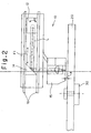
- Fig. 1 is a front view of the optical head included in the optical information storage device of the embodiment; and Fig. 2 a side view of the optical head.
- This optical head 10 includes a semiconductor laser 11 as an example of a light source of the present invention. Other than the semiconductor laser 11 as the light source of the present invention, an LED or the like is conceivable.
- the optical head 10 also includes a freely rotatable galvanomirror 12 as an example of moving means of the present invention.
- the galvanomirror 12 has a predetermined rotary shaft.
- a driving system of the galvanomirror 12 may be an electromagnetic type or an electrostatic type.
- Laser beams L emitted from the semiconductor layer 11 are set to be parallel beams by a collimation lens 13, reflected by the galvanomirror 12, further reflected by a reflecting mirror 14, and then guided to a surface of a magneto-optical disk 20 as an example of a recording medium of the present invention.
- the magneto-optical disk 20 is rotated while being held in a predetermined position by a medium holding section 30 of the optical information storage device.
- the optical head 10 further includes a slider 15 on which condensing means and a light shielding body of the present invention are loaded.
- This slider 15 is floated from the surface of the magneto-optical disk 20 by a very narrow gap d.
- the laser beams L are condensed on the surface of the magneto-optical disk 20 by the condensing means to form a condensing spot.
- a detailed structure of the slider 15 will be described later.
- tracks for storing information are provided concentric-circularly.
- a seeking operation is carried out to move the slider 15 to a desired track on the magneto-optical disk 20.
- a so-called tracking operation is carried out to hold the condensing spot on the desired track.
- Fig. 3 is a perspective view showing the detailed structure of the slider 15.
- a condensing lens 17a and a cylindrical lens 17b are loaded, which constitute an example of the condensing means of the present invention.
- the cylindrical lens 17b is loaded such that a bus is parallel to the track on the optical disk.
- the slider 15 also includes a light shielding film 18 formed as an example of a light shielding body of the present invention.
- a slit 18a is provided in the light shielding film 18.
- a plane coil 19 is provided along the light shielding film 18.
- the laser beams L reflected by the reflecting mirror 14 shown in Figs. 1 and 2 are converged by the condensing lens 17a while circular sections thereof are maintained, and further converged by the cylindrical lens 17b only in a direction orthogonal to the track of the magneto-optical disk to form an elliptic condensing spot on the slit 18a of the light shielding film 18.
- the laser beams L only a portion passed through the slit 18a is radiated onto the magneto-optical disk.
- a width W (see Fig. 5) of the slit 18a is equal to or less than 1/2 of a wavelength of the laser beam.
- the light shielding film having the slit 18a having such a width W By using the light shielding film having the slit 18a having such a width W, near light oozed out from the slit 18a forms a spot of a very small size in the direction orthogonal to the track. As a result, a spot size that cannot be realized in the conventional art using an SIL or the like is realized, making it possible to realize a much higher recording density. Moreover, since the beam passed through the slit 18a is radiated onto the magneto-optical disk to be used for information accessing, a sufficient quantity of light for information accessing can be obtained, making it possible to perform stable information accessing.
- a magneto-optical recording technology based on a laser pulse magnetic field modulation system is employed.
- the laser beams L modulated in pulse shapes of predetermined time intervals are radiated, and a recording magnetic field having a polarity reversed according to information to be recorded is generated by the plane coil 19 to form a mark on the optical disk.
- Figs. 4 and 5 are detailed views of peripheries of the slit 18a of the light shielding film 18, Fig. 4 shows a situation of the condensing spot, and Fig. 5 shows a situation of the mark formed on the magneto-optical disk.
- a center line m of the slit 18a is indicated by a dashed line, and the slit 18a is provided to intersect the track 21 by a predetermined angle ⁇ .
- the elliptic condensing spot S is formed on the slit 18a, and a major axis of the condensing spot S is parallel to the track 21.
- the condensing spot S is rotated and scanned by rotating the galvanomirror shown in Figs. 1 and 2, moved along the slit 18a as indicated by an arrow F3, and thereby a tracking operation is carried out. In other words, it is not necessary to move the light shielding body during the tracking operation.
- the condensing spot S is elliptic, even if a position of the condensing spot S is relatively shifted to a certain extent in a width direction of the slit 18a, a quantity of light passed through the slit 18a and radiated onto the optical disk is stable. In other words, since there is a margin in positioning of the condensing spot S, information accessing is stable.
- a track pitch of the track 21 is set to Tp; a focal distance of a condensing optical system composed of the condensing lens 17a and the cylindrical lens 17b to f; and a minimum changing angle for changing an advancing direction of the laser beams L by minimum rotation of the galvanomirror 12 shown in Figs. 1 and 2 to ⁇ .
- the tracking error accuracy C takes a value of at least 10 or more.
- the slit 18a and the track 21 must intersect each other by an angle ⁇ , which satisfies the following relational equation: T p / ( sin ⁇ ⁇ f ⁇ ⁇ ⁇ ) ⁇ 10
- the track pitch Tp of the magneto-optical disk is about 0.5 ⁇ m
- the tracking error accuracy C generally requested at present is about 150
- the minimum changing angle ⁇ by the normal galvanomirror is about 1 sec.
- the focal distance f of the normal condensing optical system is about 1mm.
- a light radiated onto the magneto-optical disk heats the surface of the magneto-optical disk for each pulse of the laser beam. Then, as a result of influence by a distribution of light intensities in the condensing spot S, the angle ⁇ of intersection between the slit 18a and the track 21, a rotational speed of the magneto-optical disk and the like, an elliptic region 21a is set to a predetermined temperature, which enables a polarity to be reversed by a recording magnetic field.
- the recording magnetic field is generated by the plane coil 19 shown in Fig. 3, and thus a polarity in each elliptic region 21a is set according to a polarity of the recording magnetic field.
- a position of the elliptic region 21a is shifted little by little for each laser pulse following the rotation of the magneto-optical disk. If the polarity of the recording magnetic field is constant, the region of the polarity set according to the polarity of the recording magnetic field is extended for each pulse. Then, when the polarity of the recording magnetic field is reversed, the polarity in the elliptic region 21a set to the predetermined temperature by a laser pulse at this point of time is also reversed. As a result, a crescent-shaped recording mark 21b is left, which is indicated by an oblique line in Fig. 5.
- the light radiated onto the track 21 of the magneto-optical disk through the slit 18a has the size physically reduced in the track width direction by the slit 18a as described above.
- a size of the crescent-shaped recording mark 21b formed on the track 21 in the track width direction is also small, and the track pitch can be narrowed by a corresponding amount to increase a recoding density.
- the crescent-shaped recording mark 21b a mark having longitudinal and horizontal sizes substantially equal to each other is formed.
- the foregoing angle ⁇ should be set within several degrees, and a track width and a length of a short side of the rectangular slit should be substantially equal to each other, and in the track width direction, a spot size is very small.
- a spot size In a slit longitudinal direction, no losses occur in a quantity of light, and a spot size is not so small.
- a mark size can be reduced by magnetic field modulation.
- tracking in the track width direction can be meticulously controlled.
- Fig. 6 is a conceptual configuration view showing a control system and the like of the optical information storage device of the embodiment.
- Beams emitted from the semiconductor laser 11 and set to parallel luminous fluxes by the collimation lens 13 are separated into a transmitted beam and a reflected beam by a polarizing beam splitter 40.
- the reflected beam is condensed on a photodetector 42 by a condensing lens 41, and used for light quantity monitoring of the semiconductor laser and automatic power control.
- the transmitted beam from the polarizing beam splitter 40 is passed through the galvanomirror 12 or the like, and then condensed as an irradiation light on the magneto-optical disk 20 by the condensing optical system loaded on the slider 15.
- the slider 15 is provided with the plane coil 19 (see Fig. 3), which generates a recording magnetic field.
- An input signal corresponding to information recorded in the magneto-optical disk 20 is entered from an input system 43 to a magnetic field modulation driving device 44, and a modulating signal is outputted from the magnetic field modulation driving device 44.
- a modulation recording magnetic field is generated.
- the semiconductor laser 11 emits a laser beam in a pulse shape.
- the magneto-optical disk 20 is irradiated with the laser beam based on the modulation recording magnetic field, and thus a crescent-shaped recording mark similar to that described above is formed on the magneto-optical disk 20.
- the formation of such a recording mark enables information to be stored in the magneto-optical disk 20. In this case, it is assumed that when the information is read out, only the laser beam is radiated, and no magnetic fields are generated.
- the beam transmitted through the polarizing beam splitter 40 and radiated onto the magneto-optical disk 20 is reflected by the magneto-optical disk 20, further reflected after reaching the polarizing beam splitter 40 again, and then divided into a transmitted beam and a reflected beam by a beam splitter 45.
- the beam reflected by the beam splitter 45 is used for detection of a focusing error signal.
- a knife-edge method As a method of detecting such a focusing error signal, a knife-edge method, an astigmatic method, a spot size detecting method, a critical angle method or the like is conceivable, and no problems occur even if any one of these methods is used.
- Fig. 6 shows the knife-edge method as an example, where the beam reflected by the beam splitter 45 reaches a two-division photodetector 48 through a lens 46 and a knife-edge 47. A signal from the two-division photodetector 48 is detected by a differential amplifier 49, and a focusing error signal is obtained.
- This focusing error signal is entered to a focus control system 50, and a feedback signal is entered from the focus control system 50 to a not-shown actuator.
- This actuator drives the condensing lens shown in Fig. 3 in a direction perpendicular to the magneto-optical disk 20.
- the focus control system 50 can be omitted by stabilizing a floating amount by proper means.
- the beam transmitted through the beam splitter 45 is used for tracking control and signal detection.
- a polarized component of the beam transmitted through the beam splitter 45 is separated by Wollaston prism 51, and then the beam is passed through a lens 52 to reach a two-division photodetector 53.
- a signal from the two-division photodetector 53 is detected as a magneto-optical signal by a differential amplifier 54, and entered to a detection system 55. By this detection system 55, the information stored in the magneto-optical disk 20 is obtained.
- Signals from the two-division photodetector 53 are added together by an addition amplifier 56, becoming a sample servo signal intensity-modulated by the pre-groove, and then entered to a tracking control system 57.
- the tracking control system 57 detects a tracking error signal by sample servo, and the galvanomirror 12 is rotated according to a feedback signal based on this tracking error signal.
- a tracking operation is carried out as in the case described above with reference to Fig. 4 or the like.
- the foregoing seeking operation is also controlled by the tracking control system 57 and, further, a rotational speed of the magneto-optical disk 20 by the medium holding section 30 is also controlled according to the seeking operation.
- the sampled servo system is advantageous, which uses a pit pattern for recording track positional information instead of the pre-groove.
- a servo signal is read as in the normal case of reading a reproducing signal.
- optical head according to another embodiment of the present invention.
- the optical head described hereinafter is similar to the optical head 10 shown in Figs. 1 and 2 except for the fact that a slider is different, and can be directly applied as the optical head of the foregoing optical information storage device.
- Fig. 7 is a perspective view showing the slider of the optical head of another embodiment of the present invention
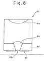
- Fig. 8 is a sectional view of the slider.
- a condensing lens 61a and a cylindrical lens 61b are loaded, which constitute an example of condensing means of the present invention.
- the slider 60 also includes a light shielding block 62 as an example of a light shielding body of the present invention, and the light shielding block 62 is provided with a slit 62a.
- a plane coil 63 is provided around the light shielding block 62.
- the light shielding block 62 is made of a silicon crystal.
- the cylindrical lens 61b is formed by providing the slit 62a in the light shielding block 62 by a photoetching technology or the like, and then laminating a semiconductor material, or the like.
- the semiconductor material a material having quality to transmit infrared rays is used and, as a light source, a semiconductor laser for emitting such infrared rays is used.
- the slider 60 using the above materials can be mass-produced inexpensively by the photoetching technology or the like. As a result, it is possible to reduce costs for the optical head and the optical information storage device.
- a situation of forming a condensing spot by the slider 60 is similar to that described above with reference to Fig. 3 and the like, and thus description thereof will be omitted to prevent repetition.
- the optical information storage device and the optical head of the present invention by shortening the wavelength of the light source, and using silicon of a high refractive index for the cylindrical lens, it is possible to realize a very small recording mark, and high efficiency of light utilization.
- the LED as the light source, a sufficiently high output can be achieved for the light source, making it possible to realize a high-speed memory at low costs.
- the recording medium of the present invention is not limited to the magneto-optical disk, and a magnetic disk using assistance by a laser beam may be used. In the case of such a magnetic disk, information reproducing is performed by using a GMR head or a spin valve head for a magnetic disk. These heads and the foregoing slider can be integrated to be used.
- the recording medium of the present invention may be an optical card using an optical tape, and this optical card has linear parallel tracks.
Landscapes
- Physics & Mathematics (AREA)
- Optics & Photonics (AREA)
- Optical Head (AREA)
Abstract
Description
- The present invention relates to an optical information storage device for accessing information by irradiating a light on a surface of a recording medium, and an optical head used for such an information storage device.
- Conventionally, as a medium for storing a voice, image information, a character, a computer program or the like, an optical disk such as a CD, a CD-ROM, a CD-R, a DVD, a PD or an MO, has been known. An optical information storage device has also been known, which forms a condensing spot by using the optical head to condense a laser beam or the like on such an optical disk, and accesses the optical disk by using the condensing spot. Such an optical information storage device is now a focus of attention because of portability of a recording medium, a large capacity and a light weight. With achievement of higher performance of a computer in recent years, there is a demand for a great increase in an information recording density by such an optical information storage device.
- The information recording density by the above-described optical information storage device is higher as a size of the condensing spot on the optical disk is smaller. Thus, developments of a shorter wavelength laser beam source, and studies of a higher NA of an objective lens have been actively conducted. Regarding achievement of the higher NA of the objective lens, there has been known a method for realizing an objective lens, which has a numerical aperture set to exceed 1 and reach about 1.4 by condensing a light in a medium of a high refractive index, as in the case of an oil immersion lens of an optical microscope. However, the size of the condensing spot cannot be greatly reduced by the shorter wavelength of the laser beam source or the higher NA of the objective lens, and thus it is difficult to greatly increase the recording density. In addition, a technology has been presented, which physically forms a condensing spot of a smaller size by using a pinhole. However, in the technology using the pinhole, a quantity of light is small, efficiency of light utilization is 0.1% or lower, and positioning of the condensing spot with respect to the pinhole is difficult. Thus, there are difficulties of stable information accessing, high-speed information transferring and reproducing. Moreover, during tracking, the condensing spot and the pinhole must be translated at a high speed. However, it is difficult to realize a low-priced actuator or the like for moving the pinhole at a high speed.
- With respect to the foregoing technologies, a magneto-optical recording technology based on a laser pulse magnetic field modulation system has been presented, which records information by a mark length smaller than the size of the condensing spot. To greatly increase the recording density, narrowing of a track pitch is essential. In the above-described magneto-optical recording technology, however, it is impossible to narrow such a track pitch.
- US 5600620 discloses an optical head apparatus including a light source, an optical modulation unit, an objective lens, a reflected beam condensing unit, and a photodetection unit. The light source emits a light beam. The optical modulation unit modulates one of a light intensity and a phase in a section of the light beam from the light source and adjusts a generation position of a side lobe light beam of the light beam. The optical modulation unit has at least a first strip-like light-shielding area inclined by a first predetermined angle with respect to a vertical axis in the section of the light beam. The objective lens focuses the light beam from the optical modulation unit to form a small spot on a recording medium. The reflected beam condensing unit condenses a reflected beam from the small spot on the recording medium. The photodetection unit detects the reflected beam from the reflected beam condensing unit to reproduce information.
- The present invention has been developed to solve the foregoing problems, and an object of the present invention is to provide an optical information storage device capable of performing stable information accessing at a high recording density, and an optical head.
- According to a first aspect of the present invention, there is provided an optical head comprising:
- a light source for emitting a light;
- a light shielding body provided with a slit for guiding a light to a surface of a recording medium; and
- condensing means for condensing the light emitted from the light source on the slit of the light shielding body;
- Such an optical head can be used for an optical storage device, and the slit provided in the light shielding body of the optical head intersects the track of the recording medium by the foregoing angle, and thus, it is possible to perform stable information accessing a high recording density.
- In addition, in an optical head embodying the present invention, preferably, the slit provided in the light shielding body has a width set equal to or less than 1/2 of a wavelength of the light emitted from the light source. Because of the slit provided to have such a width, a light called near light is oozed out from the slit to form a fine spot, making it possible to access information at a much higher recording density.
- Furthermore, in an optical head embodying the present invention, a coil may be provided along the slit of the light shielding body held in the position close to/in contact with the surface of the recording surface.
- To generate a magnetic field necessary for magneto-optical recording by a laser pulse magnetic field modulation system on the surface of the recording medium, the coil must be brought close to about 10µm from the surface of the recording medium. The foregoing coil can be brought sufficiently close to the surface of the recording medium.
- According to a second aspect of the present invention, there is provided an optical information storage device for at least performing information reproducing by irradiating a light on a surface of a recording medium, the recording medium having a track irradiated with the light to at least reproduce information, comprising: a medium holding section for holding the recording medium in a predetermined position; and an optical head, embodying the aforesaid first aspect of the present invention, for irradiating the light on the surface of the recording medium held by said medium holding section, wherein said optical head further includes a light shielding body holding section for holding the light shielding body in a position close to/in contact with the surface of the recording medium such that the slit of the light shielding body intersects the track by an angle of 45° or lower.
- In an optical information storage device embodying the second aspect of the present invention, preferably, the holding section holds the light shielding body such that the slit of the light shielding body intersects the track by an angle of 5° or lower.
- According to a third aspect of the present invention, there is provided an optical information storage device for at least performing information reproducing by irradiating a light on a surface of a recording medium, the recording medium having tracks provided at predetermined intervals and irradiated with the light to at least reproduce information, comprising: a medium holding section for holding the recording medium in a predetermined position; and an optical head, embodying the aforesaid first aspect of the invention, for irradiating the light on the surface of the recording medium held by said medium holding section, wherein: said optical head further includes a light shielding body holding section for holding the light shielding body in a position close to/in contact with the surface of the recording medium such that the slit of the light shielding body intersects the tracks by an angle of 45° or lower; said moving means are adapted to move the light condensed on the slit by the condensing means along the slit by changing an incident angle of the light made incident on the condensing means; and a following relationship is established among an interval Tp between the tracks, a focal distance f of the condensing means, a minimum changing amount Δθ of angle changed by the moving means, and an angle α of intersection of the slit with respect to the tracks: Tp/(sinα·f·Δθ)≥10.
- In this case, any tracks can be used as long as they allow information to be linearly recorded. The tracks are not limited to those physically formed as grooves, and tracks formed only magnetically or optically on a plane may also be used.
- The "slit" means an optical slit. Any slits can be used as long as they diaphragm luminous fluxes only in a predetermined direction, and a slit having a light transmitting portion filled with a transparent material such as glass may also be used.
- In addition, the light shielding body holding section may be a carriage moving on a rail, or a swing arm rotating around a predetermined point of view. The carriage or the swing arm may hold a slider having the light shielding body loaded.
- In an optical information storage device embodying either of the second and third aspects of the present invention, since the slit intersecting the track by the foregoing angle physically reduces a size of the condensing spot in a slit width direction, a track pitch can be narrowed. As a result, it is possible to perform information accessing at a high recording density. Especially, by using the device in combination with a magneto-optical recording technology based on a laser pulse magnetic field modulation system, a very high recording density can be realized. Because of no eclipsing of the condensing spot and no losses of efficiency of light utilization in a longitudinal direction of the slit, the efficiency of light utilization is high, and the recording medium can be irradiated with a sufficient quantity of light. As a result, it is possible to perform stable information accessing and high-speed data transferring. Moreover, since the light condensed on the slit is moved along the slit by the moving means, tracking accuracy is high in a direction orthogonal to the track, and thus it is possible to perform meticulous tracking control.
- In an optical information storage device embodying either of the second and third aspects of the present invention, preferably, the condensing means of the optical head condenses the light to be in a long elliptic shape in a direction parallel to the track of the recording medium. Because of such an elliptic shape of the condensing spot, accuracy of positioning the condensing spot with respect to the slit in the direction parallel to the track may be lowered.
- In addition, if the condensing means of the optical head condenses the light to be in such an elliptic shape, preferably, the condensing means includes a cylindrical lens provided on the slit of the light shielding body so as to direct a bus in a direction orthogonal to the track of the recording medium, and the light is condensed through the cylindrical lens. Furthermore, preferably,
the light source emits infrared rays,
the light shielding body is made of silicon, and
the condensing means includes a cylindrical lens made of a semiconductor transmitting the infrared rays. - The condensing means forming the condensing spot in the elliptic shape can be realized in a simple structure by using the cylindrical lens. In addition, the light shielding body and the cylindrical lens made of the foregoing materials can be mass-produced inexpensively by using a photoetching technology or the like.
- As described above, according to the optical information storage device and the optical head of the present invention, it is possible to perform stable information accessing at a high recording density.
-
- Fig. 1 is a front view of an optical head included in an optical information storage device according to an embodiment.
- Fig. 2 is a side view of the optical head included in the optical information storage device of the embodiment.
- Fig. 3 is a perspective view showing a detailed structure of a slider.
- Fig. 4 is a view showing a situation of a condensing spot on a slit of a light shielding film.
- Fig. 5 is a view showing a situation of a mark formed on a magneto-optical disk.
- Fig. 6 is a conceptual configuration view showing a control system and the like of the optical information storage device of the embodiment.
- Fig. 7 is a perspective view showing a slider in an optical head according to another embodiment of the present invention.
- Fig. 8 is a sectional view showing the slider in the optical head of the embodiment of the present invention.
- Next, description will be made of an optical information storage device according to an embodiment of the present invention, including an optical head of an embodiment of the present invention.
- Fig. 1 is a front view of the optical head included in the optical information storage device of the embodiment; and Fig. 2 a side view of the optical head.
- This
optical head 10 includes asemiconductor laser 11 as an example of a light source of the present invention. Other than thesemiconductor laser 11 as the light source of the present invention, an LED or the like is conceivable. Theoptical head 10 also includes a freelyrotatable galvanomirror 12 as an example of moving means of the present invention. Thegalvanomirror 12 has a predetermined rotary shaft. A driving system of thegalvanomirror 12 may be an electromagnetic type or an electrostatic type. - Laser beams L emitted from the
semiconductor layer 11 are set to be parallel beams by acollimation lens 13, reflected by thegalvanomirror 12, further reflected by a reflectingmirror 14, and then guided to a surface of a magneto-optical disk 20 as an example of a recording medium of the present invention. The magneto-optical disk 20 is rotated while being held in a predetermined position by amedium holding section 30 of the optical information storage device. - The
optical head 10 further includes aslider 15 on which condensing means and a light shielding body of the present invention are loaded. Thisslider 15 is floated from the surface of the magneto-optical disk 20 by a very narrow gap d. The laser beams L are condensed on the surface of the magneto-optical disk 20 by the condensing means to form a condensing spot. A detailed structure of theslider 15 will be described later. - On the surface of the magneto-
optical disk 20, tracks for storing information are provided concentric-circularly. By moving theoptical head 10 onrails 16 as indicated by an arrow F1, a seeking operation is carried out to move theslider 15 to a desired track on the magneto-optical disk 20. By rotating the galvanomirror 20 as indicated by an arrow F2, a so-called tracking operation is carried out to hold the condensing spot on the desired track. - Fig. 3 is a perspective view showing the detailed structure of the
slider 15. - On the
slider 15, a condensing lens 17a and acylindrical lens 17b are loaded, which constitute an example of the condensing means of the present invention. Here, thecylindrical lens 17b is loaded such that a bus is parallel to the track on the optical disk. Theslider 15 also includes alight shielding film 18 formed as an example of a light shielding body of the present invention. Aslit 18a is provided in thelight shielding film 18. In addition, aplane coil 19 is provided along thelight shielding film 18. - The laser beams L reflected by the reflecting
mirror 14 shown in Figs. 1 and 2 are converged by the condensing lens 17a while circular sections thereof are maintained, and further converged by thecylindrical lens 17b only in a direction orthogonal to the track of the magneto-optical disk to form an elliptic condensing spot on theslit 18a of thelight shielding film 18. Of the laser beams L, only a portion passed through theslit 18a is radiated onto the magneto-optical disk. Thus, a size of the condensing spot is physically reduced by theslit 18a. A width W (see Fig. 5) of theslit 18a is equal to or less than 1/2 of a wavelength of the laser beam. By using the light shielding film having theslit 18a having such a width W, near light oozed out from theslit 18a forms a spot of a very small size in the direction orthogonal to the track. As a result, a spot size that cannot be realized in the conventional art using an SIL or the like is realized, making it possible to realize a much higher recording density. Moreover, since the beam passed through theslit 18a is radiated onto the magneto-optical disk to be used for information accessing, a sufficient quantity of light for information accessing can be obtained, making it possible to perform stable information accessing. - In this case, a magneto-optical recording technology based on a laser pulse magnetic field modulation system is employed. The laser beams L modulated in pulse shapes of predetermined time intervals are radiated, and a recording magnetic field having a polarity reversed according to information to be recorded is generated by the
plane coil 19 to form a mark on the optical disk. - Figs. 4 and 5 are detailed views of peripheries of the
slit 18a of thelight shielding film 18, Fig. 4 shows a situation of the condensing spot, and Fig. 5 shows a situation of the mark formed on the magneto-optical disk. - In each of Figs. 4 and 5, only a portion of a number of
tracks 21 provided concentric-circularly on the optical disk is shown, and a boundary between thetracks 21 is indicated by parallel lines. A gap between thetracks 21 and a length of theslit 18a are sufficiently small with respect to a size of the optical disk. Accordingly, it can be considered that thetrack 21 is sufficiently linear when attention is paid to the periphery of theslit 18a. - In Fig. 4, a center line m of the
slit 18a is indicated by a dashed line, and theslit 18a is provided to intersect thetrack 21 by a predetermined angle α. As described above, the elliptic condensing spot S is formed on theslit 18a, and a major axis of the condensing spot S is parallel to thetrack 21. In addition, the condensing spot S is rotated and scanned by rotating the galvanomirror shown in Figs. 1 and 2, moved along theslit 18a as indicated by an arrow F3, and thereby a tracking operation is carried out. In other words, it is not necessary to move the light shielding body during the tracking operation. Moreover, since the condensing spot S is elliptic, even if a position of the condensing spot S is relatively shifted to a certain extent in a width direction of theslit 18a, a quantity of light passed through theslit 18a and radiated onto the optical disk is stable. In other words, since there is a margin in positioning of the condensing spot S, information accessing is stable. - Now, consideration is given to the angle α of intersection between the
slit 18a and thetrack 21. - A track pitch of the
track 21 is set to Tp; a focal distance of a condensing optical system composed of the condensing lens 17a and thecylindrical lens 17b to f; and a minimum changing angle for changing an advancing direction of the laser beams L by minimum rotation of thegalvanomirror 12 shown in Figs. 1 and 2 to Δθ. Then, tracking error accuracy C indicating what portion of a moving amount of the condensing spot S by the minimum rotation of thegalvanomirror 12 the track pitch Tp is equivalent to, is represented by the following relational equation:
For practical purposes, it is essential that the tracking error accuracy C takes a value of at least 10 or more. Thus, theslit 18a and thetrack 21 must intersect each other by an angle α, which satisfies the following relational equation:
- At present, the track pitch Tp of the magneto-optical disk is about 0.5µm, the tracking error accuracy C generally requested at present is about 150, the minimum changing angle Δθ by the normal galvanomirror is about 1 sec., and the focal distance f of the normal condensing optical system is about 1mm. Considering these, it can be understood from the equation (1) that the angle α of intersection between the
slit 18a and thetrack 21 should preferably be 45° or lower. Further, if the angle α is 5° or lower, specifications can be realized, where the track pitch Tp is about 0.1µm, and the tracking error accuracy C is very high, about 1000. Thus, it is possible to satisfactorily deal with future technical advancements. By setting the angle α in such a manner, tolerance of setting accuracy for optical devices, e.g., the galvanomirror, the condensing lens and the like, constituting the optical head, is high. - Next, description will be made of the recording mark formed on the magneto-optical disk by the light passed through the
slit 18a by referring to Fig. 5. - A light radiated onto the magneto-optical disk heats the surface of the magneto-optical disk for each pulse of the laser beam. Then, as a result of influence by a distribution of light intensities in the condensing spot S, the angle α of intersection between the
slit 18a and thetrack 21, a rotational speed of the magneto-optical disk and the like, anelliptic region 21a is set to a predetermined temperature, which enables a polarity to be reversed by a recording magnetic field. Here, the recording magnetic field is generated by theplane coil 19 shown in Fig. 3, and thus a polarity in eachelliptic region 21a is set according to a polarity of the recording magnetic field. In addition, a position of theelliptic region 21a is shifted little by little for each laser pulse following the rotation of the magneto-optical disk. If the polarity of the recording magnetic field is constant, the region of the polarity set according to the polarity of the recording magnetic field is extended for each pulse. Then, when the polarity of the recording magnetic field is reversed, the polarity in theelliptic region 21a set to the predetermined temperature by a laser pulse at this point of time is also reversed. As a result, a crescent-shapedrecording mark 21b is left, which is indicated by an oblique line in Fig. 5. - The light radiated onto the
track 21 of the magneto-optical disk through theslit 18a has the size physically reduced in the track width direction by theslit 18a as described above. Thus, a size of the crescent-shapedrecording mark 21b formed on thetrack 21 in the track width direction is also small, and the track pitch can be narrowed by a corresponding amount to increase a recoding density. As the crescent-shapedrecording mark 21b, a mark having longitudinal and horizontal sizes substantially equal to each other is formed. - Most preferably, the foregoing angle α should be set within several degrees, and a track width and a length of a short side of the rectangular slit should be substantially equal to each other, and in the track width direction, a spot size is very small. In a slit longitudinal direction, no losses occur in a quantity of light, and a spot size is not so small. However, a mark size can be reduced by magnetic field modulation. Moreover, even if the spot is roughly moved by the galvanomirror or the like, tracking in the track width direction can be meticulously controlled.
- Fig. 6 is a conceptual configuration view showing a control system and the like of the optical information storage device of the embodiment.
- Beams emitted from the
semiconductor laser 11 and set to parallel luminous fluxes by thecollimation lens 13 are separated into a transmitted beam and a reflected beam by apolarizing beam splitter 40. The reflected beam is condensed on aphotodetector 42 by a condensinglens 41, and used for light quantity monitoring of the semiconductor laser and automatic power control. - The transmitted beam from the
polarizing beam splitter 40 is passed through thegalvanomirror 12 or the like, and then condensed as an irradiation light on the magneto-optical disk 20 by the condensing optical system loaded on theslider 15. - The
slider 15 is provided with the plane coil 19 (see Fig. 3), which generates a recording magnetic field. An input signal corresponding to information recorded in the magneto-optical disk 20 is entered from aninput system 43 to a magnetic fieldmodulation driving device 44, and a modulating signal is outputted from the magnetic fieldmodulation driving device 44. When this modulating signal is entered to theplane coil 19, a modulation recording magnetic field is generated. On the other hand, thesemiconductor laser 11 emits a laser beam in a pulse shape. The magneto-optical disk 20 is irradiated with the laser beam based on the modulation recording magnetic field, and thus a crescent-shaped recording mark similar to that described above is formed on the magneto-optical disk 20. The formation of such a recording mark enables information to be stored in the magneto-optical disk 20. In this case, it is assumed that when the information is read out, only the laser beam is radiated, and no magnetic fields are generated. - The beam transmitted through the
polarizing beam splitter 40 and radiated onto the magneto-optical disk 20 is reflected by the magneto-optical disk 20, further reflected after reaching thepolarizing beam splitter 40 again, and then divided into a transmitted beam and a reflected beam by abeam splitter 45. - The beam reflected by the
beam splitter 45 is used for detection of a focusing error signal. As a method of detecting such a focusing error signal, a knife-edge method, an astigmatic method, a spot size detecting method, a critical angle method or the like is conceivable, and no problems occur even if any one of these methods is used. Fig. 6 shows the knife-edge method as an example, where the beam reflected by thebeam splitter 45 reaches a two-division photodetector 48 through alens 46 and a knife-edge 47. A signal from the two-division photodetector 48 is detected by adifferential amplifier 49, and a focusing error signal is obtained. This focusing error signal is entered to afocus control system 50, and a feedback signal is entered from thefocus control system 50 to a not-shown actuator. This actuator drives the condensing lens shown in Fig. 3 in a direction perpendicular to the magneto-optical disk 20. - Here, since the
slider 15 is floated with respect to the surface of the magneto-optical disk 20, thefocus control system 50 can be omitted by stabilizing a floating amount by proper means. - The beam transmitted through the
beam splitter 45 is used for tracking control and signal detection. A polarized component of the beam transmitted through thebeam splitter 45 is separated byWollaston prism 51, and then the beam is passed through alens 52 to reach a two-division photodetector 53. A signal from the two-division photodetector 53 is detected as a magneto-optical signal by adifferential amplifier 54, and entered to adetection system 55. By thisdetection system 55, the information stored in the magneto-optical disk 20 is obtained. - Regarding a system of providing the foregoing track on the magneto-
optical disk 20, here as an example, it is assumed that a system of providing a pre-groove on the magneto-optical disk 20 and using it as a boundary between the tracks is employed. The system of providing such a pre-groove enables the surface of the magneto-optical disk 20 to be smooth. As a result, it is possible to bring theslider 15 sufficiently close to the surface of the magneto-optical disk 20. - Signals from the two-
division photodetector 53 are added together by anaddition amplifier 56, becoming a sample servo signal intensity-modulated by the pre-groove, and then entered to atracking control system 57. Thetracking control system 57 detects a tracking error signal by sample servo, and thegalvanomirror 12 is rotated according to a feedback signal based on this tracking error signal. As a result, a tracking operation is carried out as in the case described above with reference to Fig. 4 or the like. Here, the foregoing seeking operation is also controlled by thetracking control system 57 and, further, a rotational speed of the magneto-optical disk 20 by themedium holding section 30 is also controlled according to the seeking operation. - When the angle α of intersection between the
slit 18a and the track becomes smaller, a return beam from theslit 18a becomes weaker. In this case, the sampled servo system is advantageous, which uses a pit pattern for recording track positional information instead of the pre-groove. In this sampled servo system, a servo signal is read as in the normal case of reading a reproducing signal. - By the foregoing configuration, it is possible to realize an optical information storage device, which is large in capacity and high in data transfer speed.
- Next, description will be made of an optical head according to another embodiment of the present invention. The optical head described hereinafter is similar to the
optical head 10 shown in Figs. 1 and 2 except for the fact that a slider is different, and can be directly applied as the optical head of the foregoing optical information storage device. - Fig. 7 is a perspective view showing the slider of the optical head of another embodiment of the present invention, and Fig. 8 is a sectional view of the slider.
- On this
slider 60, a condensinglens 61a and a cylindrical lens 61b are loaded, which constitute an example of condensing means of the present invention. - The
slider 60 also includes alight shielding block 62 as an example of a light shielding body of the present invention, and thelight shielding block 62 is provided with aslit 62a. In addition, aplane coil 63 is provided around thelight shielding block 62. - The
light shielding block 62 is made of a silicon crystal. The cylindrical lens 61b is formed by providing theslit 62a in thelight shielding block 62 by a photoetching technology or the like, and then laminating a semiconductor material, or the like. However, as the semiconductor material, a material having quality to transmit infrared rays is used and, as a light source, a semiconductor laser for emitting such infrared rays is used. Theslider 60 using the above materials can be mass-produced inexpensively by the photoetching technology or the like. As a result, it is possible to reduce costs for the optical head and the optical information storage device. - A situation of forming a condensing spot by the
slider 60 is similar to that described above with reference to Fig. 3 and the like, and thus description thereof will be omitted to prevent repetition. - In the optical information storage device and the optical head of the present invention, by shortening the wavelength of the light source, and using silicon of a high refractive index for the cylindrical lens, it is possible to realize a very small recording mark, and high efficiency of light utilization. In addition, by using the LED as the light source, a sufficiently high output can be achieved for the light source, making it possible to realize a high-speed memory at low costs.
- Furthermore, the recording medium of the present invention is not limited to the magneto-optical disk, and a magnetic disk using assistance by a laser beam may be used. In the case of such a magnetic disk, information reproducing is performed by using a GMR head or a spin valve head for a magnetic disk. These heads and the foregoing slider can be integrated to be used. Moreover, the recording medium of the present invention may be an optical card using an optical tape, and this optical card has linear parallel tracks.
Claims (7)
- An optical head comprising:a light source (11) for emitting a light;a light shielding body (18; 62) provided with a slit (18a; 62c) for guiding the light to a surface of a recording medium (20); andcondensing means (17a; 61a) for condensing the light emitted from said light source on the slit of said light shielding body;characterised by moving means (12) for moving the light condensed on the slit by said condensing means along the slit.
- An optical head according to claim 1, wherein the slit provided in said light shielding body has a width set equal to or less than 1/2 of a wavelength of the light emitted from said light source.
- An optical head according to claim 1 or 2, further comprising a coil (19; 63) provided close to the slit of said light shielding body to generate a magnetic field.
- An optical information storage device for at least performing information reproducing by irradiating a light on a surface of a recording medium (20), the recording medium having a track irradiated with the light to at least reproduce information, comprising:a medium holding section (30) for holding the recording medium in a predetermined position; andan optical head (10), as claimed in any preceding claim, for irradiating the light on the surface of the recording medium held by said medium holding section,wherein said optical head further includes a light shielding body holding section (15) for holding the light shielding body in a position close to/in contact with the surface of the recording medium such that the slit of the light shielding body intersects the track by an angle of 45° or lower.
- An optical information storage device according to claim 4, wherein the holding section holds the light shielding body such that the slit of the light shielding body intersects the track by an angle of 5° or lower.
- An optical information storage device according to claim 4 or 5, wherein the condensing means of said optical head condenses the light to be in a long elliptic shape in a direction parallel to the track of the recording medium.
- An optical information storage device for at least performing information reproducing by irradiating a light on a surface of a recording medium (20), the recording medium having tracks provided at predetermined intervals and irradiated with the light to at least reproduce information, comprising:a medium holding section (30) for holding the recording medium in a predetermined position; andan optical head (10), as claimed in any one of claims 1 to 3, for irradiating the light on the surface of the recording medium held by said medium holding section,
wherein:said optical head further includes a light shielding body holding section (15) for holding the light shielding body in a position close to/in contact with the surface of the recording medium such that the slit of the light shielding body intersects the tracks by an angle of 45° or lower;said moving means (12) are adapted to move the light condensed on the slit by the condensing means along the slit by changing an incident angle of the light made incident on the condensing means; anda following relationship is established among an interval Tp between the tracks, a focal distance f of the condensing means, a minimum changing amount Δθ of angle changed by the moving means, and an angle α of intersection of the slit with respect to the tracks:
Applications Claiming Priority (1)
| Application Number | Priority Date | Filing Date | Title |
|---|---|---|---|
| PCT/JP1999/006284 WO2001035399A1 (en) | 1999-11-11 | 1999-11-11 | Optical information storage and optical head |
Publications (3)
| Publication Number | Publication Date |
|---|---|
| EP1229525A1 EP1229525A1 (en) | 2002-08-07 |
| EP1229525A4 EP1229525A4 (en) | 2005-10-19 |
| EP1229525B1 true EP1229525B1 (en) | 2006-10-18 |
Family
ID=14237255
Family Applications (1)
| Application Number | Title | Priority Date | Filing Date |
|---|---|---|---|
| EP99974164A Expired - Lifetime EP1229525B1 (en) | 1999-11-11 | 1999-11-11 | Optical head and optical information storage device |
Country Status (5)
| Country | Link |
|---|---|
| US (1) | US6563781B2 (en) |
| EP (1) | EP1229525B1 (en) |
| JP (1) | JP4392149B2 (en) |
| DE (1) | DE69933708T2 (en) |
| WO (1) | WO2001035399A1 (en) |
Families Citing this family (6)
| Publication number | Priority date | Publication date | Assignee | Title |
|---|---|---|---|---|
| JP2002050001A (en) * | 2000-05-23 | 2002-02-15 | Sharp Corp | Information recording and reproducing head, information recording and reproducing device, tracking device and information recording medium |
| US6735005B2 (en) * | 2001-11-09 | 2004-05-11 | Tokyo Seimitso (Israel) Ltd. | Cartesian scanning system |
| KR100792593B1 (en) * | 2005-10-12 | 2008-01-09 | 한국정보통신대학교 산학협력단 | Method for formating single pulse pattern by using a ultrashort pulse laser and its system |
| WO2014163897A1 (en) * | 2013-03-13 | 2014-10-09 | Optimedica Corporation | Free floating patient interface for laser surgery system |
| EP3434235B1 (en) | 2013-03-13 | 2023-04-26 | AMO Development, LLC | Laser eye surgery system |
| WO2015066216A1 (en) | 2013-10-29 | 2015-05-07 | Optical Archive Inc. | Array reader and array reading of optical media |
Family Cites Families (13)
| Publication number | Priority date | Publication date | Assignee | Title |
|---|---|---|---|---|
| JPS57108811A (en) * | 1980-12-26 | 1982-07-07 | Hitachi Ltd | Optical focus position detector |
| US4742219A (en) * | 1981-09-17 | 1988-05-03 | Tokyo Shibaura Denki Kabushiki Kaisha | Apparatus for detecting the focusing state and positional accuracy of a light beam directed onto an optical disk tracking guide in an optical read/write system |
| JPS62112245A (en) * | 1985-11-12 | 1987-05-23 | Olympus Optical Co Ltd | Recording and reproducing device for optical recording disk |
| JPS6363137A (en) * | 1986-09-02 | 1988-03-19 | Seiko Epson Corp | Optical head |
| JPH0619845B2 (en) * | 1986-09-26 | 1994-03-16 | ティアツク株式会社 | Disk fluctuation state detection device |
| JPH01232581A (en) | 1988-03-11 | 1989-09-18 | Hitachi Ltd | Position detecting device |
| US5125750A (en) | 1991-03-14 | 1992-06-30 | The Board Of Trustees Of The Leland Stanford Junior University | Optical recording system employing a solid immersion lens |
| JP3019181B2 (en) | 1993-12-27 | 2000-03-13 | 日本電気株式会社 | Optical head servo signal detection device |
| US5600620A (en) * | 1994-11-08 | 1997-02-04 | Nec Corporation | Optical head apparatus having means to eliminate noise caused by side-lobes |
| DE69620495T2 (en) * | 1995-02-02 | 2002-10-10 | Pioneer Electronic Corp., Tokio/Tokyo | Optical scanning device and identification device for identifying the type of an optical recording medium |
| JP3071141B2 (en) | 1995-06-12 | 2000-07-31 | 三洋電機株式会社 | Optical recording or optical reproducing device |
| JPH10162443A (en) | 1996-12-02 | 1998-06-19 | Sanyo Electric Co Ltd | Information reproducing device |
| JPH10320826A (en) | 1997-03-14 | 1998-12-04 | Sanyo Electric Co Ltd | Optical pickup device and optical recording medium driving device using the same |
-
1999
- 1999-11-11 DE DE69933708T patent/DE69933708T2/en not_active Expired - Lifetime
- 1999-11-11 JP JP2001537053A patent/JP4392149B2/en not_active Expired - Fee Related
- 1999-11-11 EP EP99974164A patent/EP1229525B1/en not_active Expired - Lifetime
- 1999-11-11 WO PCT/JP1999/006284 patent/WO2001035399A1/en active IP Right Grant
-
2002
- 2002-03-14 US US10/097,317 patent/US6563781B2/en not_active Expired - Fee Related
Also Published As
| Publication number | Publication date |
|---|---|
| EP1229525A1 (en) | 2002-08-07 |
| EP1229525A4 (en) | 2005-10-19 |
| WO2001035399A1 (en) | 2001-05-17 |
| US20020093903A1 (en) | 2002-07-18 |
| US6563781B2 (en) | 2003-05-13 |
| DE69933708D1 (en) | 2006-11-30 |
| DE69933708T2 (en) | 2007-02-22 |
| JP4392149B2 (en) | 2009-12-24 |
Similar Documents
| Publication | Publication Date | Title |
|---|---|---|
| EP0414380B1 (en) | Optical recording and reproducing apparatus and adaptor for use with said apparatus | |
| JPH03102647A (en) | Optical head | |
| US6992968B2 (en) | Optical head and disk unit | |
| EP1811511A2 (en) | Optical recording/reprducing apparatus, optical pickup, and tracking error detecting method | |
| JP4038336B2 (en) | Information recording and playback method | |
| KR100241984B1 (en) | Magneto optical recording/reproducing apparatus | |
| US4977552A (en) | Split type optical pick-up device with a tracking error detector on the moving part | |
| US5594711A (en) | Optical recording and reproducing apparatus using a plurality of light spots for recording and reproducing | |
| EP1229525B1 (en) | Optical head and optical information storage device | |
| KR20000029090A (en) | Magneto-optical head device having integrated auxiliary lens and magnetic reproducing haed and recording and reproducing device using magneto-optical head device | |
| JPS5982646A (en) | Optomagnetic storage device | |
| JPH09293247A (en) | Optical disk initialization device | |
| CN101010740A (en) | Optical scanning device | |
| JP2563261B2 (en) | Optical information recording / reproducing device | |
| JP2000207765A (en) | Optical head, optical part and optical memory | |
| KR100392255B1 (en) | Near-field optical data storage head minimized by using SIL | |
| JPH0644601A (en) | Optical information recording and reproducing device and adjusting method therefor | |
| JP3580040B2 (en) | Optical pickup device and disc player device | |
| JPH06325404A (en) | Information memory device | |
| JP2002032941A (en) | Head position adjusting method and recording/ reproducing device | |
| JPH07169085A (en) | Optical information recorder/reproducer | |
| JP2006012336A (en) | Disk-like recording medium and disk device | |
| JPS61273750A (en) | Automatic focus controller | |
| JPH03224142A (en) | Optical head and control method thereof | |
| JP2000076697A (en) | Magneto-optical head device |
Legal Events
| Date | Code | Title | Description |
|---|---|---|---|
| PUAI | Public reference made under article 153(3) epc to a published international application that has entered the european phase |
Free format text: ORIGINAL CODE: 0009012 |
|
| 17P | Request for examination filed |
Effective date: 20020225 |
|
| AK | Designated contracting states |
Kind code of ref document: A1 Designated state(s): AT BE CH CY DE DK ES FI FR GB GR IE IT LI LU MC NL PT SE |
|
| AX | Request for extension of the european patent |
Free format text: AL;LT;LV;MK;RO;SI |
|
| RBV | Designated contracting states (corrected) |
Designated state(s): DE FR GB |
|
| A4 | Supplementary search report drawn up and despatched |
Effective date: 20050905 |
|
| GRAP | Despatch of communication of intention to grant a patent |
Free format text: ORIGINAL CODE: EPIDOSNIGR1 |
|
| RTI1 | Title (correction) |
Free format text: OPTICAL HEAD AND OPTICAL INFORMATION STORAGE DEVICE |
|
| GRAS | Grant fee paid |
Free format text: ORIGINAL CODE: EPIDOSNIGR3 |
|
| GRAA | (expected) grant |
Free format text: ORIGINAL CODE: 0009210 |
|
| AK | Designated contracting states |
Kind code of ref document: B1 Designated state(s): DE FR GB |
|
| REG | Reference to a national code |
Ref country code: GB Ref legal event code: FG4D |
|
| REF | Corresponds to: |
Ref document number: 69933708 Country of ref document: DE Date of ref document: 20061130 Kind code of ref document: P |
|
| ET | Fr: translation filed | ||
| PLBE | No opposition filed within time limit |
Free format text: ORIGINAL CODE: 0009261 |
|
| STAA | Information on the status of an ep patent application or granted ep patent |
Free format text: STATUS: NO OPPOSITION FILED WITHIN TIME LIMIT |
|
| 26N | No opposition filed |
Effective date: 20070719 |
|
| PGFP | Annual fee paid to national office [announced via postgrant information from national office to epo] |
Ref country code: GB Payment date: 20131106 Year of fee payment: 15 Ref country code: FR Payment date: 20131108 Year of fee payment: 15 Ref country code: DE Payment date: 20131106 Year of fee payment: 15 |
|
| REG | Reference to a national code |
Ref country code: DE Ref legal event code: R119 Ref document number: 69933708 Country of ref document: DE |
|
| GBPC | Gb: european patent ceased through non-payment of renewal fee |
Effective date: 20141111 |
|
| REG | Reference to a national code |
Ref country code: FR Ref legal event code: ST Effective date: 20150731 |
|
| PG25 | Lapsed in a contracting state [announced via postgrant information from national office to epo] |
Ref country code: GB Free format text: LAPSE BECAUSE OF NON-PAYMENT OF DUE FEES Effective date: 20141111 Ref country code: DE Free format text: LAPSE BECAUSE OF NON-PAYMENT OF DUE FEES Effective date: 20150602 |
|
| PG25 | Lapsed in a contracting state [announced via postgrant information from national office to epo] |
Ref country code: FR Free format text: LAPSE BECAUSE OF NON-PAYMENT OF DUE FEES Effective date: 20141201 |