JP4391209B2 - Ventilation system - Google Patents

Ventilation system Download PDF

Info

Publication number
JP4391209B2
JP4391209B2 JP2003387557A JP2003387557A JP4391209B2 JP 4391209 B2 JP4391209 B2 JP 4391209B2 JP 2003387557 A JP2003387557 A JP 2003387557A JP 2003387557 A JP2003387557 A JP 2003387557A JP 4391209 B2 JP4391209 B2 JP 4391209B2
Authority
JP
Japan
Prior art keywords
air
passage
ventilation
passage portion
room
Prior art date
Legal status (The legal status is an assumption and is not a legal conclusion. Google has not performed a legal analysis and makes no representation as to the accuracy of the status listed.)
Expired - Fee Related
Application number
JP2003387557A
Other languages
Japanese (ja)
Other versions
JP2005147565A5 (en
JP2005147565A (en
Inventor
勇 川渕
裕信 中村
和彦 遠藤
Current Assignee (The listed assignees may be inaccurate. Google has not performed a legal analysis and makes no representation or warranty as to the accuracy of the list.)
Mitsubishi Electric Corp
Original Assignee
Mitsubishi Electric Corp
Priority date (The priority date is an assumption and is not a legal conclusion. Google has not performed a legal analysis and makes no representation as to the accuracy of the date listed.)
Filing date
Publication date
Application filed by Mitsubishi Electric Corp filed Critical Mitsubishi Electric Corp
Priority to JP2003387557A priority Critical patent/JP4391209B2/en
Publication of JP2005147565A publication Critical patent/JP2005147565A/en
Publication of JP2005147565A5 publication Critical patent/JP2005147565A5/ja
Application granted granted Critical
Publication of JP4391209B2 publication Critical patent/JP4391209B2/en
Anticipated expiration legal-status Critical
Expired - Fee Related legal-status Critical Current

Links

Images

Description

本発明は、給気流と排気流との間で熱交換しながら居室の換気を行う空調換気扇に関するものである。   The present invention relates to an air-conditioning fan that ventilates a room while exchanging heat between a supply air flow and an exhaust air flow.

従来のこの種の換気システムは、給気及び排気による換気を可能な複数の部屋からなる気密住宅において、排気を強制的に行なうように設定した複数の部屋に排気手段としてそれぞれ風量可変の排気用換気装置を設け、これらの排気用換気装置の特定の一つを、基準換気装置として、当該基準換気装置を通過する風量が設定風量になるような換気駆動指令信号を生成し、基準換気装置への給電を制御する制御装置によって、前記換気駆動指令信号を基準換気装置に対応するチャンネルの通電率制御回路により制御し、基準換気装置以外の他の排気用換気装置については、制御装置に備えた個別の他のチャンネルの通電率制御回路により前記換気駆動指令信号に基づきそれぞれ独立に各排気用換気装置の風量特性に応じた電源を供給するように構成して、基準換気装置と他の排気用換気装置との換気風量を均衡させるようにしている(例えば特許文献1)。   This type of conventional ventilation system is used in an airtight house consisting of a plurality of rooms that can be ventilated with air supply and exhaust. A ventilation device is provided, and a specific one of these exhaust ventilation devices is used as a reference ventilation device, and a ventilation drive command signal is generated so that the amount of air passing through the reference ventilation device becomes the set air volume, and to the reference ventilation device The ventilation drive command signal is controlled by the power supply rate control circuit of the channel corresponding to the reference ventilation device by the control device that controls the power supply of the exhaust gas. Other exhaust ventilation devices other than the reference ventilation device are provided in the control device. A power supply according to the air flow characteristics of each exhaust ventilation device is independently supplied based on the ventilation drive command signal by the energization rate control circuit of another individual channel. Form and, so that to balance the ventilation power of the reference ventilator and other exhaust ventilator (for example, Patent Document 1).

かかる換気システムによれば、気密性のある戸建住宅にも容易に適用でき、風量特性の異なる排気用換気装置であっても対応することが可能となる。   According to such a ventilation system, it can be easily applied to an airtight detached house, and even an exhaust ventilation device having different air volume characteristics can be used.

特開平9−318110号公報JP-A-9-318110

しかしながら、従来の換気システムは、各部屋を個々に換気することを前提として成されており、住宅全体を効率良く換気して気流が流れる床下や側面側通路部となる壁の中のカビ等の発生を防止する機能は持っていない。 However, the conventional ventilation system is based on the premise that each room is individually ventilated, and the entire house is efficiently ventilated, such as mold in the wall under the floor or side wall where airflow flows . It does not have a function to prevent the occurrence.

本発明の技術的課題は、住宅全体を効率良く換気できて気流が流れる床下や側面側通路部となる壁の中のカビ等の発生を防止できるようにすることにある。
The technical problem of the present invention is to efficiently ventilate the entire house and to prevent the occurrence of mold and the like in the wall that becomes the underfloor and side passage portions where airflow flows .

本発明に係る換気システムは、複数の部屋を有する外断熱の住宅の床下に設けられて気流が流れる床下通路部と、住宅の側面側に床下通路部と連通させて設けられた側面側通路部と、住宅の天井側に側面側通路部と連通させて設けられた天井通路部と、屋外から外気を取り込み、屋内の内気を排出させるとともに、内気の一部を循環させる換気手段と、この換気手段と床下通路部とを接続する第1のダクトと、換気手段と部屋とを接続する第2のダクトと、換気手段により取り込んだ外気の流路を第1のダクトと第2のダクトとの間で切り換える風路切換え手段と、前記部屋の内気を換気手段に連なる通路に向けて排出する排気口と、前記部屋に側面側通路部の第1のダクトからの外気を給気する換気ファンと、を備えたものである。 The ventilation system according to the present invention includes an underfloor passage portion that is provided under the floor of an externally insulated house having a plurality of rooms and through which airflow flows, and a side passage portion that is provided in communication with the underfloor passage portion on the side of the house. When the ceiling passage portion provided ceiling side surface side passage portion and is communicated with the housing, I Capture the outside air from the outdoors, with discharging the inside air of the indoor, and ventilation means for circulating a portion of the inside air, A first duct connecting the ventilation means and the underfloor passage portion, a second duct connecting the ventilation means and the room, and a flow path of outside air taken in by the ventilation means, the first duct and the second duct. Air path switching means for switching between, an exhaust port for discharging the room's inside air toward a passage connected to the ventilation means, and ventilation for supplying outside air from the first duct of the side passage section to the room And a fan .

本発明に係る換気システムにおいては、風路切換え手段により部屋または床下通路部に気流を送出して住宅の部屋、床下通路部、側面側通路部、天井通路部を気流が循環し、換気手段を介して内気を住宅外に排出して換気できる。このため、特に床下のカビ、結露の発生を抑制できるとともに、風路切換え手段により部屋の空調および換気もできるという効果がある。また、部屋の内気を換気手段に連なる通路に向けて排出する排気口と、部屋に側面側通路部の第1のダクトからの外気を給気する換気ファンを設けているので、外気を供給する換気手段からのダクトを床下通路部に連通させるだけで、側面側通路部を介して各部屋の換気ファンにより、各部屋へ外気を取り込むことができる。このため、各部屋への換気のためのダクト配管は基本的に必要なくなる。 In the ventilation system according to the present invention, the airflow is sent to the room or the underfloor passage by the airway switching means, and the airflow circulates through the room, underfloor passage, the side passage portion, and the ceiling passage portion of the house. The inside air can be exhausted outside the house and ventilated. For this reason, in particular, it is possible to suppress the occurrence of mold and dew condensation under the floor, and it is possible to effect air conditioning and ventilation of the room by the air path switching means. Moreover, since the room is provided with an exhaust port for discharging the room air toward the passage connected to the ventilation means, and the room is provided with a ventilation fan for supplying outside air from the first duct of the side passage section, the outside air is supplied. By merely communicating the duct from the ventilation means to the underfloor passage portion, the outside air can be taken into each room by the ventilation fan of each room via the side passage portion. For this reason, duct piping for ventilation to each room is basically unnecessary.

実施の形態1.
以下、図示実施形態により本発明を説明する。
図1乃至図4はいずれも本発明の請求項1,8,9,10,11に係る換気システムを示すもので、図1は本実施の形態1に係る換気システムを導入した住宅の縦断面図、図2は図1に示す住宅の一部断面を有する斜視図、図3は図1に示す熱交換型換気扇に係る熱交換器の模式図、図4は図1の換気システムの電気配線図である。
Embodiment 1 FIG.
The present invention will be described below with reference to illustrated embodiments.
1 to 4 all show a ventilation system according to claims 1, 8, 9, 10, and 11 of the present invention, and FIG. 1 is a longitudinal section of a house in which the ventilation system according to the first embodiment is introduced. FIG. 2, FIG. 2 is a perspective view having a partial cross section of the house shown in FIG. 1, FIG. 3 is a schematic diagram of a heat exchanger according to the heat exchange type exhaust fan shown in FIG. 1, and FIG. FIG.

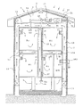
この実施の形態1の換気システムは、本発明を二階建て住宅1に適用したものである。この住宅1は、屋根裏3及び四つの部屋R1〜R4を有し、高断熱、高気密で外張り断熱工法によって建築されており、住宅1の外側全体に発泡プラスチック等の断熱材7が張り巡らされ、屋根5に太陽電池41が固定設置されている。   The ventilation system according to the first embodiment is an application of the present invention to a two-story house 1. This house 1 has an attic 3 and four rooms R1 to R4, and is constructed by a highly heat-insulated, air-tight and heat-insulated outer construction method, and a heat insulating material 7 such as foamed plastic is stretched around the entire outside of the house 1. The solar cell 41 is fixedly installed on the roof 5.

また住宅1には、床下の上面と部屋R1,R2の下面との間に気流を通過させる床下通路部11と、床下通路部11と連通するとともに、側面の断熱材7と部屋R1,R3又はR2,R4の端部との間に気流を通過させる側面側通路部13と、側面側通路部13と連通するとともに、屋根5の下面と部屋R3,R4の上面との間に気流を通過させる天井通路部15と、側面側通路部13と連通するとともに、一階の部屋R1,R2と二階の部屋R3,R4との間に気流を通過させる階間通路部17と、天井通路部15及び床下通路部11に連通されるとともに、部屋R1,R2と部屋R3,R4との間に気流を通過させる部屋間通路部19とが形成されており、気流が床下通路部11から側面側通路部13を通り天井通路部15に流れたり、床下通路部11から部屋間通路部19を通り天井通路部15に流れたり、床下通路部11から側面側通路部13を通り階間通路部17を通過して、更に側面側通路部13を通り天井通路部15に流れたりするように構成されている。   In addition, the house 1 communicates with the underfloor passage portion 11 for allowing airflow to pass between the upper surface under the floor and the lower surfaces of the rooms R1 and R2, and the underfloor passage portion 11 and the side heat insulating material 7 and the rooms R1, R3 or The side surface passage portion 13 that allows airflow to pass between the end portions of R2 and R4, and the side surface passage portion 13 communicate with the airflow between the lower surface of the roof 5 and the upper surfaces of the rooms R3 and R4. An inter-floor passage portion 17 that communicates with the ceiling passage portion 15 and the side-surface passage portion 13 and allows airflow to pass between the first floor rooms R1 and R2 and the second floor rooms R3 and R4, and the ceiling passage section 15 and An inter-room passage portion 19 is formed between the rooms R1 and R2 and the rooms R3 and R4. The inter-room passage portion 19 is formed between the rooms R1 and R2 and the rooms R3 and R4. 13 to the ceiling passage 15 and The lower passage portion 11 passes through the inter-room passage portion 19 to the ceiling passage portion 15, or the lower floor passage portion 11 passes through the side passage portion 13, passes through the inter-floor passage portion 17, and further passes through the side passage portion 13. It is comprised so that it may flow into the ceiling channel | path part 15. FIG.

屋根裏3には、スイッチSWLによりオン・オフ操作される外気用空調手段すなわち熱交換型換気扇21が設けられ、熱交換型換気扇21には、そのハウジング内に熱交換器21E(図3)が設けられている。熱交換器21Eは、間隔板21aと仕切り板21cとにより互いに直交する内気流路A1及び外気流路A2が層状に形成され、これによって内気取込通路RA、外気取込通路OA、内気排出通路EA、外気排出通路SAが形成されていて、内気流路A1を通過する内気と外気流路A2を通過する外気との間で潜熱および顕熱が交換されるようになっている。なお、熱交換器21Eは、これが占有するエリア(平面の面積S)を大きくし、間隔板21aと仕切り板21cとにより形成される段の数を少なくし、高さを屋根裏最狭部の高さよりも低く設定することが望ましい。このようにすることにより、コンパクトな設置が可能となる。   The attic 3 is provided with an air-conditioning means for outside air that is turned on / off by a switch SWL, that is, a heat exchange type ventilation fan 21, and the heat exchange type ventilation fan 21 is provided with a heat exchanger 21E (FIG. 3) in its housing. It has been. In the heat exchanger 21E, an internal air flow path A1 and an external air flow path A2 that are orthogonal to each other are formed in layers by a spacing plate 21a and a partition plate 21c, whereby an internal air intake passage RA, an external air intake passage OA, an internal air discharge passage The EA and the outside air discharge passage SA are formed, and latent heat and sensible heat are exchanged between the inside air passing through the inside air passage A1 and the outside air passing through the outside air passage A2. The heat exchanger 21E increases the area occupied by the heat exchanger (planar area S), reduces the number of steps formed by the spacing plates 21a and the partition plates 21c, and increases the height of the narrowest part of the attic. It is desirable to set lower than this. In this way, a compact installation is possible.

また、屋根裏3には、熱交換型換気扇21に接続された内気用空調手段すなわち空調機31が設けられている。空調機31は、温度制御すなわち冷暖房の機能と、温度を制御せずに除湿する機能とを有し、スイッチSWaによりオン・オフ操作されるようになっている。また空調機31には、天井通路部15の気流を取り込む内気取込通路RAと、外気や循環流を風路切換えダンパ35を介して床下を含む屋内の複数個所に選択的に送り込む外気排出通路SAが備えられている。すなわち、風路切換えダンパ35には、屋根裏3から床下まで延設された第1のダクトとなる床下ダクト37により床下通路部11に接続された外気排出通路SA1と、屋根裏3から各部屋R1〜R4まで延設された第2のダクトとなる部屋ダクト39(図では部屋R3のダクトのみ示す)により各部屋にそれぞれ接続された外気排出通路SA2とが接続されており、ダンパ切換スイッチSWdにより、外気の排出通路が、外気排出通路SA1と外気排出通路SA2の間で切換えられるように構成されている。   The attic 3 is provided with air-conditioning means for inside air, that is, an air conditioner 31 connected to the heat exchange type ventilation fan 21. The air conditioner 31 has a temperature control, that is, a function of air conditioning, and a function of dehumidifying without controlling the temperature, and is turned on / off by a switch SWa. Further, the air conditioner 31 includes an internal air intake passage RA that takes in the airflow of the ceiling passage portion 15 and an external air discharge passage that selectively sends outside air and a circulating flow to a plurality of indoor locations including the floor under the airway switching damper 35. SA is provided. That is, the air path switching damper 35 includes an outside air discharge passage SA1 connected to the underfloor passage portion 11 by an underfloor duct 37 serving as a first duct extending from the attic 3 to the underfloor, and the rooms R1 to R1 from the attic 3. The room duct 39 (only the duct of the room R3 is shown in the figure) that is a second duct extending to R4 is connected to the outside air discharge passage SA2 connected to each room, and the damper changeover switch SWd The outside air discharge passage is configured to be switched between the outside air discharge passage SA1 and the outside air discharge passage SA2.

各部屋R1〜R4には、側面側通路部13との間に給気用の換気ファンF1〜F4と、部屋間通路部19との間に排気口E1〜E4とが設けられている。換気ファンF1〜F4には、それぞれに気流の流れを解放する蓋と、粉塵などを補集するフィルタとが取付けられ、換気ファンスイッチSW1〜SW4によりオン・オフ操作されるようになっているとともに、各換気ファンスイッチSW1〜SW4のオン・オフ操作に連動して蓋が開閉されるようになっている。   In each of the rooms R <b> 1 to R <b> 4, ventilation fans F <b> 1 to F <b> 4 for supplying air are provided between the side passage portions 13 and exhaust ports E <b> 1 to E <b> 4 are provided between the inter-room passage portions 19. Each of the ventilation fans F1 to F4 is provided with a lid for releasing the flow of airflow and a filter for collecting dust and the like, and is turned on and off by ventilation fan switches SW1 to SW4. The lid is opened and closed in conjunction with the on / off operation of the ventilation fan switches SW1 to SW4.

この換気システムの電源系統は、太陽電池41により得られる電源と商用電源の2系統あり、電源切換え手段にて、いずれかの電源に切り換えられるようになっている。電源切換え手段は、太陽電池41の直流出力電圧Vdを交流電圧Vcに変換するインバータ45と、直流出力電圧Vdを検出する電圧計43aと、検出された直流出力電圧Vdと予め設定された電圧とを比較する比較器43bと、比較器43bの出力に基づいて直流出力電圧Vdが設定電圧を超えたか否かを判断して、超えている場合にはスイッチSWcをインバータ45に切換えさせ、越えていない場合にはスイッチSWcを商用電源に切換えさせる切換電圧判定手段43cとから構成されている。なお、メインスイッチSWmを介して各スイッチSWd,SW1〜SW4,SWL,SWaが接続されている。   There are two power supply systems for the ventilation system: a power supply obtained by the solar battery 41 and a commercial power supply, and can be switched to any one of the power supplies by the power supply switching means. The power source switching means includes an inverter 45 that converts the DC output voltage Vd of the solar battery 41 into an AC voltage Vc, a voltmeter 43a that detects the DC output voltage Vd, a detected DC output voltage Vd, and a preset voltage. Based on the output of the comparator 43b and the output of the comparator 43b, it is determined whether or not the DC output voltage Vd exceeds the set voltage. In the absence of the switch SWc, the switch SWc is switched to a commercial power source. Each switch SWd, SW1 to SW4, SWL, SWa is connected through the main switch SWm.

次に、前述のように構成された本実施の形態の換気システムの動作について図1乃至図4に基づき説明する。いま、快晴で、太陽電池41から十分な直流出力電圧Vdが発生していると切換電圧判定手段43cが判定すると、スイッチSWcがインバータ45側に切り換えられる。これにより、電源が太陽電池41に切り換えられ、インバータ45が動作して太陽電池41からの直流出力電圧Vdを交流電圧Vcに変換して出力する。ここで、各換気ファンのスイッチSW1〜SW4をオフにし、メインスイッチSWm、熱交換型換気扇21のスイッチSWL、空調機31のスイッチSWaを、それぞれオンにするとともに、ダンパ切換スイッチSWdをSA1側(床下側)に投入すると、外気取込通路OAから外気が強制的に取り込まれる。   Next, the operation of the ventilation system according to the present embodiment configured as described above will be described with reference to FIGS. If the switching voltage determination means 43c determines that the solar battery 41 generates a sufficient DC output voltage Vd, the switch SWc is switched to the inverter 45 side. As a result, the power source is switched to the solar cell 41, and the inverter 45 operates to convert the DC output voltage Vd from the solar cell 41 into the AC voltage Vc and output it. Here, the switches SW1 to SW4 of each ventilation fan are turned off, the main switch SWm, the switch SWL of the heat exchange type ventilation fan 21 and the switch SWa of the air conditioner 31 are turned on, and the damper changeover switch SWd is turned on the SA1 side ( When it is introduced into the lower floor), the outside air is forcibly taken in from the outside air intake passage OA.

外気取込通路OAから取り込まれた外気は、熱交換型換気扇21、空調機31を通り、風路切換えダンパ35が端子SA1側に投入されているので、床下ダクト37から外気排出通路SA1を通過して床下通路部11に排出される。床下通路部11に排出された外気は、床下を分流して両側の側面側通路部13を通り、下方から上方に通過する間に一部が階間通路部17にも分流して階間通路部17を図中矢印で示すように通過して、天井通路部15に至り、天井通路部15内に開口する内気取込通路RAから熱交換型換気扇21を介して内気排出通路EAを通過して住宅1の外部に放出される。また前述のように各通路部を通過して天井通路部15内に至った内気の一部は、空調機31の内気取込通路RAより取り込まれて循環流となる。このようにして住宅1内の床下通路部11、側面側通路部13、階間通路部17、天井通路部15を換気することができる。したがって、カビ、結露の発生を抑制できる。   Since the outside air taken in from the outside air intake passage OA passes through the heat exchange type ventilation fan 21 and the air conditioner 31, and the air path switching damper 35 is introduced to the terminal SA1 side, it passes through the outside air discharge passage SA1 from the underfloor duct 37. Then, it is discharged to the underfloor passage portion 11. The outside air discharged to the underfloor passage portion 11 is diverted under the floor, passes through the side passage portions 13 on both sides, and a part is also diverted to the interfloor passage portion 17 while passing from below to above. Passing through the portion 17 as indicated by the arrow in the figure, reaches the ceiling passage portion 15, and passes through the inside air discharge passage EA from the inside air intake passage RA opening in the ceiling passage portion 15 via the heat exchange type ventilation fan 21. To the outside of the house 1. Further, as described above, a part of the inside air that has passed through each passage portion and reached the ceiling passage portion 15 is taken in from the inside air intake passage RA of the air conditioner 31 and becomes a circulating flow. In this way, the underfloor passage portion 11, the side passage portion 13, the inter-floor passage portion 17, and the ceiling passage portion 15 in the house 1 can be ventilated. Therefore, generation | occurrence | production of mold | fungi and dew condensation can be suppressed.

次に、各換気ファンのスイッチSW1〜SW4をオンにすると、気流は側面側通路部13から各換気ファンF1〜F4によりフィルタを介して各部屋R1〜R4に取り込まれ、各部屋R1〜R4内を循環して排出口E1〜E4から部屋間通路部19を通過して天井通路部15に至り、内気取込通路RAから熱交換型換気扇21を介して内気排出通路EAを通過して住宅1の外部に放出される。また天井通路部15内に至った内気の一部は、空調機31の内気取込通路RAより取り込まれて循環流となる。このようにして住宅1の各部屋R1〜R4を換気、空調することができる。   Next, when the switches SW1 to SW4 of the ventilation fans are turned on, the airflow is taken into the rooms R1 to R4 through the filters by the ventilation fans F1 to F4 from the side-side passage portion 13, and in the rooms R1 to R4. Circulates through the outlets E1 to E4 through the inter-room passage part 19 to the ceiling passage part 15, and passes through the inside air discharge passage EA from the inside air intake passage RA through the heat exchange ventilator 21 to the house 1 Released to the outside. A part of the inside air reaching the ceiling passage portion 15 is taken in from the inside air intake passage RA of the air conditioner 31 and becomes a circulating flow. Thus, each room R1-R4 of the house 1 can be ventilated and air-conditioned.

ここで、各換気ファンのスイッチSW1〜SW4をオフにし、メインスイッチSWm、熱交換型換気扇21のスイッチSWL、空調機31のスイッチSWaをオンするとともに、ダンパ切換スイッチSWdをSA2側(部屋側)に投入すると、外気取込通路OAから強制的に取り込まれ外気は、熱交換型換気扇21、空調機31を通り、各部屋ダクト39から各外気排出通路SA2を通過して各部屋R1〜R4に排出される。排出された外気は、各部屋R1〜R4内を循環して各排出口E1〜E4から部屋間通路部19を介して天井通路部15に至り、内気取込通路RAから熱交換型換気扇21を介して内気排出通路EAを通過して住宅1の外部に放出される。また天井通路部15内に至った内気の一部は、空調機31の内気取込通路RAより取り込まれて循環流となる。このようにして住宅1の各部屋R1〜R4を換気、空調することができる。なお、ここでは、熱交換型換気扇21及び空調機31の両方を有する換気システムを例に挙げて説明したが、熱交換型換気扇21又は空調機31のいずれか一つのみ用いた換気システムでもよいことは言うまでもない。このことは後述する他の実施の形態においても同様である。   Here, the switches SW1 to SW4 of each ventilation fan are turned off, the main switch SWm, the switch SWL of the heat exchange type ventilation fan 21 and the switch SWa of the air conditioner 31 are turned on, and the damper changeover switch SWd is set to the SA2 side (room side). , The outside air is forcibly taken in from the outside air intake passage OA, passes through the heat exchange type ventilation fan 21 and the air conditioner 31, passes from each room duct 39 to each outside air discharge passage SA2, and enters each room R1 to R4. Discharged. The discharged outside air circulates through the rooms R1 to R4 and reaches the ceiling passage 15 through the passages 19 between the discharge ports E1 to E4, and the heat exchange type ventilation fan 21 from the inside air intake passage RA. Through the inside air discharge passage EA and discharged to the outside of the house 1. A part of the inside air reaching the ceiling passage portion 15 is taken in from the inside air intake passage RA of the air conditioner 31 and becomes a circulating flow. Thus, each room R1-R4 of the house 1 can be ventilated and air-conditioned. Here, although the ventilation system having both the heat exchange type ventilation fan 21 and the air conditioner 31 has been described as an example, a ventilation system using only one of the heat exchange type ventilation fan 21 or the air conditioner 31 may be used. Needless to say. The same applies to other embodiments described later.

このように、本実施の形態の換気システムにおいては、複数の部屋R1〜R4を有する外断熱の住宅1の床下に設けられて気流が流れる床下通路部11と、住宅1の側面側に床下通路部11と連通させて設けられた側面側通路部13と、住宅1の天井側に側面側通路部13と連通させて設けられた天井通路部15と、屋外から外気を取り込むとともに、屋内の内気を排出する換気手段すなわち熱交換型換気扇21および空調機31と、空調機31と床下通路部11とを接続する第1のダクトすなわち床下ダクト37と、空調機31と部屋R1〜R4とを接続する第2のダクトすなわち部屋ダクト39と、換気手段により取り込んだ外気の流路を床下ダクト37と部屋ダクト39の間で切り換える風路切換え手段すなわち風路切換えダンパ35と、部屋の内気を換気手段に連なる通路、つまり部屋間通路部19に向けて排出する部屋内気排出部すなわち換気ファンF1〜F4および排気口E1〜E4と、を備えているので、風路切換えダンパ35により部屋または床下通路部11に気流を送出して住宅1の部屋、床下通路部11、側面側通路部13、階間通路部17、天井通路部15を気流が循環し、天井通路部15から換気手段を介して内気を住宅外に排出して換気できる。このため、特に床下のカビ、結露の発生を抑制できるとともに、風路切換え手段により部屋の空調および換気もできるという効果がある。   As described above, in the ventilation system of the present embodiment, the underfloor passage portion 11 provided under the floor of the externally insulated house 1 having a plurality of rooms R1 to R4 and the airflow flows, and the underfloor passage on the side of the house 1 A side passage portion 13 provided in communication with the portion 11, a ceiling passage portion 15 provided in communication with the side passage portion 13 on the ceiling side of the house 1, and outside air from the outside, Connecting the air conditioner 31 and the rooms R1 to R4, the first duct connecting the air conditioner 31 and the underfloor passage portion 11, that is, the underfloor duct 37, and the ventilation means for discharging the air, that is, the heat exchange type ventilation fan 21 and the air conditioner 31 The second duct, that is, the room duct 39, and the air path switching means, that is, the air path switching damper 35, for switching the flow path of the outside air taken in by the ventilation means between the underfloor duct 37 and the room duct 39. The air passage switching damper is provided with a room internal air discharge section that discharges the room internal air to the passage connecting to the ventilation means, that is, the room air passage section 19, that is, the ventilation fans F1 to F4 and the exhaust ports E1 to E4. 35, the airflow is sent to the room or the underfloor passage portion 11, and the airflow circulates through the room of the house 1, the underfloor passage portion 11, the side surface passage portion 13, the interstitial passage portion 17, and the ceiling passage portion 15, and the ceiling passage portion 15 The inside air can be discharged outside the house through the ventilation means. For this reason, in particular, it is possible to suppress the occurrence of mold and dew condensation under the floor, and it is possible to effect air conditioning and ventilation of the room by the air path switching means.

また、換気手段は、外気と内気との間で熱交換する熱交換器21Eを備えているとともに、熱交換器21Eの高さを屋根裏最狭部の高さよりも低く設定されているので、熱交換器21Eが薄型化し、屋根裏3などに容易に設置することができる。   The ventilation means includes a heat exchanger 21E for exchanging heat between the outside air and the inside air, and the height of the heat exchanger 21E is set lower than the height of the narrowest part of the attic. The exchanger 21E is thin and can be easily installed in the attic 3 or the like.

また、換気手段は、外気を取り込むとともに、内気を排出する外気用空調手段すなわち熱交換型換気扇21を備えているので、部屋等を外気によって換気することができる。   Further, since the ventilation means includes the outside air conditioning means for taking in the outside air and discharging the inside air, that is, the heat exchange type ventilation fan 21, the room or the like can be ventilated with the outside air.

また、換気手段は、内気の温度を下降または上昇させる冷暖房機能と、内気温度を制御せずに除湿する除湿機能とを有する内気用空調手段すなわち空調機31を備えているので、各部屋の湿度を空調機31によって容易に調整することができる。   In addition, the ventilation means includes an air-conditioning means for air, that is, an air conditioner 31 having a cooling / heating function for lowering or raising the temperature of the inside air and a dehumidifying function for dehumidifying without controlling the inside air temperature. Can be easily adjusted by the air conditioner 31.

また、住宅1は屋根5に太陽電池41が設置され、電源系統が太陽電池41により得られる電源と商用電源の2系統あり、太陽電池41の出力電圧が設定電圧以上の時に電源切換え手段によって電源が太陽電池側に切り換えられるようにしているので、太陽エネルギを有効に利用することができる。   The house 1 has a solar battery 41 installed on the roof 5 and has two power systems, a power source obtained from the solar cell 41 and a commercial power source. When the output voltage of the solar cell 41 is equal to or higher than a set voltage, the power source is switched by the power source switching means. Can be switched to the solar cell side, so that solar energy can be used effectively.

実施の形態2.
図5は本発明の請求項1,2,8,9,10,11に係る換気システムを導入した住宅の縦断面図であり、図中、前述の実施の形態1のもの(図1)と同一部分には同一符号を付し、その説明は省略する。なお、説明にあたっては前述の図4の電気配線図を参照するものとする。
Embodiment 2. FIG.
FIG. 5 is a longitudinal sectional view of a house into which a ventilation system according to claims 1, 2, 8, 9, 10, and 11 of the present invention is introduced. In FIG. The same parts are denoted by the same reference numerals, and the description thereof is omitted. In the description, the above-described electrical wiring diagram of FIG. 4 will be referred to.

この実施の形態2の換気システムは、屋根裏3に、前述の実施の形態1のものと同様に外気用空調手段すなわち熱交換型換気扇(ここでは外気空調機という)25と、この外気空調機25に接続された内気用空調手段すなわち空調機31と、風路切換えダンパ35が設けられていて、外気取込通路OAより取り込まれた外気の排出先が、風路切換えダンパ35により床下ダクト37と部屋ダクト39との間で切り換えられるようになっている。なお、部屋ダクト39は各部屋R1〜R4までそれぞれ延設されているが、ここでも部屋R3のダクトのみ示す。   In the ventilation system of the second embodiment, an air-conditioning means for outside air, that is, a heat exchange type ventilation fan (herein referred to as an outside-air air conditioner) 25, and the outside-air air conditioner 25 are provided on the attic 3 in the same manner as in the first embodiment. The air-conditioning means for the inside air, that is, the air conditioner 31 and the air path switching damper 35 are connected to the outside air, and the discharge destination of the outside air taken in from the outside air intake passage OA is connected to the underfloor duct 37 by the air path switching damper 35. Switching between the room duct 39 is possible. The room duct 39 extends from the rooms R1 to R4, but only the duct of the room R3 is shown here.

部屋R1には、床の一側に暖房機50が設けられているとともに、天井にこの室内の空気を階間通路部17に排出する排気ファンFSが設けられている。さらに、階間通路部17の左端部には、排気ファンFSからの気流を階間通路部17内に取り込むとともに、左側の側面側通路部13からの気流の進入を阻止するガイドGLが設けられている。なお、暖房機50の外機52が住宅1の外に設置されている。つまり、部屋R1には、前述の実施の形態1のような壁面設置の換気ファンF1と排気口E1が無く、代わり天井設置の排気ファンFSが設けられている。したがって、電気配線図は図4中の換気ファンF1を排気ファンFSに置き換えた構成となりスイッチSW1は排気ファンスイッチとなる。それ以外の構成は前述の実施の形態1のものと同様である。   In the room R1, a heater 50 is provided on one side of the floor, and an exhaust fan FS that discharges air in the room to the inter-floor passage portion 17 is provided on the ceiling. Furthermore, a guide GL is provided at the left end portion of the interstitial passage portion 17 to take in the airflow from the exhaust fan FS into the interstitial passage portion 17 and prevent the airflow from entering from the left side passage portion 13. ing. An outer unit 52 of the heater 50 is installed outside the house 1. That is, the room R1 does not have the wall-mounted ventilation fan F1 and the exhaust port E1 as in the first embodiment, but is provided with the ceiling-mounted exhaust fan FS instead. Therefore, the electrical wiring diagram has a configuration in which the ventilation fan F1 in FIG. 4 is replaced with the exhaust fan FS, and the switch SW1 is an exhaust fan switch. Other configurations are the same as those of the first embodiment.

この実施の形態2の換気システムにおいて、いま、部屋R1の暖房機50を運転し、排気ファンスイッチSW1と各換気ファンのスイッチSW2〜SW4をオンし、メインスイッチSWm、外気空調機25のスイッチSWL、空調機31のスイッチSWaを、それぞれオンにするとともに、ダンパ切換スイッチSWdをSA1側(床下側)に投入すると、排気ファンFSが駆動されて部屋R1の暖かい空気を階間通路部17に暖気流として排出すると、暖気流が階間通路部17内を右方向に流れて、その右端に連通する側面側通路部13から天井通路部15に流れ、前述の実施の形態1のように天井通路部15内に開口する内気取込通路RAから外気空調機25を介して内気排出通路EAを通過して住宅1の外部に放出される。   In the ventilation system of the second embodiment, the heater 50 in the room R1 is now operated, the exhaust fan switch SW1 and the switches SW2 to SW4 of each ventilation fan are turned on, the main switch SWm, and the switch SWL of the outside air conditioner 25. When the switch SWa of the air conditioner 31 is turned on and the damper changeover switch SWd is turned on to the SA1 side (under the floor), the exhaust fan FS is driven to warm the warm air in the room R1 to the interstitial passage portion 17. When discharged as an airflow, the warm airflow flows rightward in the interstitial passage portion 17 and flows from the side-side passage portion 13 communicating with the right end to the ceiling passage portion 15, and the ceiling passage as in the first embodiment. The inside air intake passage RA that opens into the portion 15 passes through the inside air discharge passage EA via the outside air conditioner 25 and is discharged to the outside of the house 1.

また、外気取込通路OAから外気が強制的に取り込まれ、取り込まれ外気が、外気空調機25、空調機31を通り、風路切換えダンパ35により床下ダクト37側へ向きを変えられ、外気排出通路SA1を通過して床下通路部11に排出される。床下通路部11に排出された外気は、床下を分流して両側の側面側通路部13を通り、下方から上方に通過して、天井通路部15に至り、内気取込通路RAから外気空調機25を介して内気排出通路EAを通過して住宅1の外部に放出される。   Further, outside air is forcibly taken in from the outside air intake passage OA, and the taken outside air passes through the outside air conditioner 25 and the air conditioner 31 and is turned to the underfloor duct 37 side by the air path switching damper 35 to discharge outside air. It passes through the passage SA1 and is discharged to the underfloor passage portion 11. The outside air discharged to the underfloor passage portion 11 is diverted under the floor, passes through the side passage portions 13 on both sides, passes from the lower side to the upper side, reaches the ceiling passage portion 15, and passes through the inside air intake passage RA to the outside air conditioner. The air passes through the inside air discharge passage EA via 25 and is discharged to the outside of the house 1.

また、側面側通路部13を下方から上方に通過する気流の一部は、各換気ファンF2〜F4によりフィルタを介して各部屋R2〜R4に取り込まれ、各部屋R2〜R4内を循環して排出口E2〜E4から部屋間通路部19を通過して天井通路部15に至り、内気取込通路RAから外気空調機25を介して内気排出通路EAを通過して住宅1の外部に放出される。   A part of the airflow passing through the side passage 13 from below to above is taken into the rooms R2 to R4 through the filters by the ventilation fans F2 to F4, and circulates in the rooms R2 to R4. The exhaust ports E2 to E4 pass through the inter-room passage portion 19 to the ceiling passage portion 15, and are discharged from the inside air intake passage RA through the outside air conditioner 25 to the outside of the house 1 through the inside air discharge passage EA. The

また、前述のように各通路部を通過して天井通路部15内に至った暖気と外気を含む内気の一部は、空調機31の内気取込通路RAより取り込まれて循環流となる。このようにして住宅1内の床下通路部11、側面側通路部13、天井通路部15を換気しながら、階間通路部17すなわち二階の部屋R3,R4の床下を効率よく暖房できる。   Further, as described above, a part of the inside air including the warm air and the outside air that has passed through each passage portion and reached the ceiling passage portion 15 is taken in from the inside air intake passage RA of the air conditioner 31 and becomes a circulating flow. In this way, the underfloor passage portion 17, that is, the underfloor of the rooms R3 and R4 on the second floor can be efficiently heated while ventilating the underfloor passage portion 11, the side passage portion 13, and the ceiling passage portion 15 in the house 1.

ここで、各換気ファンのスイッチSW2〜SW4と空調機31のスイッチSWaをオフにし、メインスイッチSWm、外気空調機25のスイッチSWL、及び排気ファンスイッチSW1をオンにするとともに、スイッチSWdをSA2側(部屋側)に投入すると、外気取込通路OAから取り込まれ外気は、外気空調機25の運転により停止中の空調機31を通過して、風路切換えダンパ35により各部屋ダクト39側へ向きを変えられ、各部屋ダクト39から各外気排出通路SA2を通過して各部屋R1〜R4に排出される。排出された外気は、それぞれの部屋R1〜R4内を循環して、部屋R2〜R4内の空気は、排出口E2〜E4から部屋間通路部19を通過して天井通路部15に流れ、また部屋R1内の空気は、排気ファンFSにより階間通路部17に排出されて、階間通路部17内を右方向に流れて、右側の側面側通路部13から天井通路部15に流れ、内気取込通路RAから外気空調機25を介して内気排出通路EAを通過して住宅1の外部に放出される。   Here, the switches SW2 to SW4 of each ventilation fan and the switch SWa of the air conditioner 31 are turned off, the main switch SWm, the switch SWL of the outside air conditioner 25, and the exhaust fan switch SW1 are turned on, and the switch SWd is switched to the SA2 side. When it is introduced into the room side, the outside air is taken in from the outside air intake passage OA, passes through the air conditioner 31 that is stopped by the operation of the outside air conditioner 25, and is directed to the room duct 39 side by the air path switching damper 35. Are changed, and each room duct 39 passes through each outside air discharge passage SA2 and is discharged to each room R1 to R4. The discharged outside air circulates in the rooms R1 to R4, and the air in the rooms R2 to R4 flows from the discharge ports E2 to E4 through the inter-room passage portion 19 to the ceiling passage portion 15, The air in the room R1 is discharged to the interstitial passage portion 17 by the exhaust fan FS, flows in the interstitial passage portion 17 in the right direction, flows from the right side surface passage portion 13 to the ceiling passage portion 15, and flows into the interior air. From the intake passage RA, the outside air conditioner 25 passes through the inside air discharge passage EA and is discharged to the outside of the house 1.

このように、本実施の形態の換気システムにおいても、住宅1の各部屋R1〜R4に外気を取り込んで換気することができる。   Thus, also in the ventilation system of the present embodiment, it is possible to take outside air into the rooms R1 to R4 of the house 1 and ventilate.

また、一階の暖房の排気(暖気)を階間通路部17に流すことができて、一階の暖房の排気を利用して二階の床暖房を行うことができ、省エネルギ化が可能となる。   Further, the first floor heating exhaust (warm air) can flow to the inter-floor passage section 17, and the second floor floor heating can be performed using the first floor heating exhaust, which can save energy. Become.

実施の形態3.
図6は本発明の請求項1,3,4,5,8,9,10,11に係る換気システムを導入した住宅の縦断面図、図7は図6の換気システムの開閉ダンパの制御ブロック図であり、図6中、前述の実施の形態1の図1と同一部分には同一符号を付し、その説明は省略する。
Embodiment 3 FIG.
6 is a longitudinal sectional view of a house in which a ventilation system according to claims 1, 3, 4, 5, 8, 9, 10, and 11 of the present invention is introduced, and FIG. 7 is a control block of an opening / closing damper of the ventilation system of FIG. In FIG. 6, the same reference numerals are given to the same portions as those in FIG.

この実施の形態3の換気システムは、一階の部屋R2に隣接させて浴室が設けられており、浴室には、部屋R2との隔壁に、浴室内に開口するダクト61が貫通して設けられている。ダクト61には、その両端側に開閉ダンパG1,G2を有する排出口D1,D2が設けられていて、各排出口D1,D2から一階の部屋R1,R2に浴室内の湿気を排出できるようになっている。また、ダクト61にはこれから分岐して上方に延びるダクト63、65が接続され、これらダクト63、65の上端部に開閉ダンパG3,G4を有する排出口D3,D4が設けられていて、これら排出口D3,D4からそれぞれ二階の部屋R3,R4にも浴室内の湿気を排出できるようになっている。また浴室には、その天井に第1の湿気排出手段となる開閉ダンパGbを有する排出口Ebが設けられているとともに、その側壁に換気ファンFbが設けられていて、排出口Ebから階間通路部17に浴室内の湿気を排出できるようになっている。また部屋R2には、前述の図1及び図5で説明したような換気ファンF2は設置されておらず、その排出口(図1及び図5のE2部分参照)に排気ファンFS2が設けられている。また前述の実施の形態1のものと同様、ここでも外気取込通路OAより取り込まれた外気の排出先が、風路切換えダンパ35により床下ダクト37と部屋ダクト39との間で切り換えられるようになっていて、部屋ダクト39は各部屋R1〜R4までそれぞれ延設されているが、部屋R3のダクトのみ示す。なお、各部屋R1〜R4には、湿度を検出する湿度センサS1〜S4が設置されている。   In the ventilation system of the third embodiment, a bathroom is provided adjacent to the room R2 on the first floor. In the bathroom, a duct 61 that opens into the bathroom is provided in a partition wall with the room R2. ing. The duct 61 is provided with discharge ports D1 and D2 having opening / closing dampers G1 and G2 on both ends thereof, so that moisture in the bathroom can be discharged from the discharge ports D1 and D2 to the rooms R1 and R2 on the first floor. It has become. The duct 61 is connected to ducts 63 and 65 that are branched from the duct 63 and extend upward. The upper ends of the ducts 63 and 65 are provided with discharge ports D3 and D4 having opening and closing dampers G3 and G4. Moisture in the bathroom can be discharged from the outlets D3 and D4 to the rooms R3 and R4 on the second floor, respectively. Further, the bathroom is provided with a discharge port Eb having an opening / closing damper Gb serving as a first moisture discharge means on the ceiling, and a ventilation fan Fb is provided on the side wall thereof. The part 17 can discharge moisture in the bathroom. Further, the room R2 is not provided with the ventilation fan F2 as described with reference to FIGS. 1 and 5 described above, and the exhaust fan FS2 is provided at the exhaust port (see the portion E2 in FIGS. 1 and 5). Yes. Similarly to the first embodiment, the discharge destination of the outside air taken in from the outside air intake passage OA is switched between the underfloor duct 37 and the room duct 39 by the air path switching damper 35 here. The room duct 39 extends to each of the rooms R1 to R4, but only the duct of the room R3 is shown. In each of the rooms R1 to R4, humidity sensors S1 to S4 that detect humidity are installed.

開閉ダンパG1〜G4,Gbの開閉は、湿度センサS1〜S4が検出した各部屋の湿度に基づいて行われる。すなわち、湿度センサS1〜S4により検出された湿度が予め定められた湿度以下なら開閉ダンパG1〜G4を開放するとともに、開閉ダンパGbを閉じて、浴室内の湿気を各部屋R1〜R4内に排出する。逆に湿度センサS1〜S4により検出された湿度が予め定められた湿度以上ならば、開閉ダンパG1〜G4を閉じるとともに、開閉ダンパGbを開放して、浴室内の湿気を階間通路部17に排出する。これを実現するため、図7において、湿度センサS1〜S4がインターフェイス(以下、I/Fという)71,73,75,77を介してCPU81に接続され、CPU81にRAM83、ROM85が接続されており、CPU81にI/F91,93,95,97,99を介して開閉ダンパG1〜G4,Gbが接続されて、前述のように開閉ダンパG1〜G4,Gbの開閉制御が行われるようになっている。それ以外の構成は前述の実施の形態1のものと同様である。   The open / close dampers G1 to G4 and Gb are opened and closed based on the humidity of each room detected by the humidity sensors S1 to S4. That is, if the humidity detected by the humidity sensors S1 to S4 is equal to or lower than a predetermined humidity, the open / close dampers G1 to G4 are opened, the open / close damper Gb is closed, and the moisture in the bathroom is discharged into the rooms R1 to R4. To do. On the contrary, if the humidity detected by the humidity sensors S1 to S4 is equal to or higher than a predetermined humidity, the open / close dampers G1 to G4 are closed and the open / close damper Gb is opened so that moisture in the bathroom is transferred to the interstitial passage portion 17. Discharge. In order to realize this, in FIG. 7, humidity sensors S1 to S4 are connected to the CPU 81 via interfaces (hereinafter referred to as I / F) 71, 73, 75, 77, and the RAM 83 and ROM 85 are connected to the CPU 81. The open / close dampers G1 to G4 and Gb are connected to the CPU 81 via the I / Fs 91, 93, 95, 97 and 99, and the open / close control of the open / close dampers G1 to G4 and Gb is performed as described above. Yes. Other configurations are the same as those of the first embodiment.

この実施の形態3の換気システムにおいて、いま、風路が切換えダンパ35により床下ダクト37側へ切り換えられていて、空調機31、熱交換型換気扇21が動作して床下通路部11、階間通路部17、側面側通路部13、天井通路部15を気流が流れ温度、湿度が制御されているものとする。かかる状態から空調機31を停止した状態において、CPU81は、各部屋R1〜R4の湿度センサS1〜S4からの各湿度信号をI/F71〜77を介して取込み、予め定めた湿度を超えたか否かを判断する。   In the ventilation system of the third embodiment, the air path is switched to the underfloor duct 37 side by the switching damper 35, and the air conditioner 31 and the heat exchange type ventilation fan 21 are operated to operate the underfloor passage portion 11 and the interfloor passage. It is assumed that the airflow flows through the portion 17, the side passage portion 13, and the ceiling passage portion 15, and the temperature and humidity are controlled. In a state where the air conditioner 31 is stopped from such a state, the CPU 81 fetches each humidity signal from the humidity sensors S1 to S4 of each room R1 to R4 via the I / F 71 to 77, and whether or not the predetermined humidity is exceeded. Determine whether.

ここで、検出湿度が予め定めた湿度よりも低いと判断された場合、CPU81は、換気ファンFbを駆動させて浴室に側面側通路部13からの空気を取り込ませるとともに、開閉ダンパGbを閉じさせ、開閉ダンパG1〜G4を開放させる。これにより、排出口D1〜D4から浴室の湿気の多い空気が部屋R1〜R4に流れ込み、室内が加湿される。   Here, when it is determined that the detected humidity is lower than the predetermined humidity, the CPU 81 drives the ventilation fan Fb to cause the bathroom to take in air from the side-side passage portion 13 and closes the open / close damper Gb. Then, the open / close dampers G1 to G4 are opened. Thereby, the humid air of the bathroom flows into the rooms R1 to R4 from the discharge ports D1 to D4, and the room is humidified.

また、湿度センサS1〜S4の検出湿度が予め定めた湿度よりも高いと判断されると、CPU81は、I/F91〜99を介して開閉ダンパG1〜G4を閉じさせるとともに、開閉ダンパGbを開放させる。これにより、排出口Ebから湿気の多い空気が階間通路部17に排出され、階間通路部17から側面側通路部13、天井通路部15を経て、天井通路部15内に開口する内気取込通路RAから熱交換型換気扇21を介して内気排出通路EAを通過して住宅1の外部に放出される。なお、前述のダンパの開閉制御による各部屋R1〜R4の湿度調整は、排出口D1〜D4の近傍で、部屋R1〜R4内の空気と浴室の空気との湿度比が1:4〜1:5となるように調整するのが望ましく、この範囲内に調整することで、部屋全体における適度な湿気の保持が可能となる。   When it is determined that the humidity detected by the humidity sensors S1 to S4 is higher than the predetermined humidity, the CPU 81 closes the open / close dampers G1 to G4 and opens the open / close damper Gb via the I / Fs 91 to 99. Let As a result, humid air is discharged from the discharge port Eb to the interstitial passage portion 17, and the internal air opening that opens into the ceiling passage portion 15 from the interstitial passage portion 17 through the side passage portion 13 and the ceiling passage portion 15. It passes through the inside air discharge passage EA via the heat exchange type ventilation fan 21 from the entrance passage RA and is discharged to the outside of the house 1. The humidity adjustment of each of the rooms R1 to R4 by the damper opening / closing control described above is performed in the vicinity of the discharge ports D1 to D4 so that the humidity ratio between the air in the rooms R1 to R4 and the bathroom air is 1: 4 to 1: It is desirable to adjust so that it becomes 5, and by adjusting within this range, moderate humidity can be maintained in the entire room.

このように、本実施の形態の換気システムにおいては、各部屋R1〜R4にダクト61,63,65を介して浴室の湿気を送り込めるようにしているので、加湿器のように浴室の湿気を用いることができる。   As described above, in the ventilation system of the present embodiment, the bathroom moisture can be sent to the rooms R1 to R4 via the ducts 61, 63, 65, so that the bathroom moisture is supplied like a humidifier. Can be used.

また、各部屋R1〜R4に湿度センサS1〜S4を設置して、湿度センサS1〜S4が検出した各部屋の湿度に基づき、各開閉ダンパG1〜G4,Gbの開閉制御を行うようにしているので、浴室からの湿った空気を利用して各部屋の湿度を適切な値にできる。   In addition, humidity sensors S1 to S4 are installed in the rooms R1 to R4, and the open / close control of the open / close dampers G1 to G4 and Gb is performed based on the humidity of each room detected by the humidity sensors S1 to S4. Therefore, the humidity of each room can be set to an appropriate value using the humid air from the bathroom.

また、浴室の天井に開閉ダンパGbを有する排出口Ebを設けるとともに、浴室の側壁に換気ファンFbを設けて、排出口Ebから階間通路部17に浴室内の湿気を強制排出できるようにしているので、浴室を換気することができる。   In addition, a discharge port Eb having an opening / closing damper Gb is provided on the ceiling of the bathroom, and a ventilation fan Fb is provided on the side wall of the bathroom so that moisture in the bathroom can be forcibly discharged from the discharge port Eb to the interstitial passage portion 17. So you can ventilate the bathroom.

実施の形態4.
図8は本発明の請求項1,6,8,9,10,11に係る換気システムを導入した住宅の縦断面図であり、図中、前述の実施の形態1の図1と同一部分には同一符号を付し、その説明は省略する。
Embodiment 4 FIG.
FIG. 8 is a longitudinal sectional view of a house into which a ventilation system according to claims 1, 6, 8, 9, 10, and 11 of the present invention is introduced. In the figure, the same part as that of FIG. Are denoted by the same reference numerals, and the description thereof is omitted.

この実施の形態4の換気システムは、階間通路部17の右端に閉鎖板101を設けて、階間通路部17の右端を封鎖するとともに、浴室の天井部に、階間通路部17に連通する排出口Ebを設け、さらに浴室の右側壁部に、浴室の空気を住宅1の外部に直接放出するためのダクト103を備えた排気ファンFSbを設けたもので、排出口Ebとダクト103及び排気ファンFSbにより第2の湿気排出手段が構成されている。それ以外の構成は前述の実施の形態1のものと同様である。   In the ventilation system of the fourth embodiment, the closing plate 101 is provided at the right end of the interstitial passage portion 17 to block the right end of the interstitial passage portion 17 and communicated with the interstitial passage portion 17 on the ceiling of the bathroom. And an exhaust fan FSb provided with a duct 103 for directly discharging bathroom air to the outside of the house 1 is provided on the right side wall of the bathroom. The exhaust fan FSb constitutes a second moisture discharge means. Other configurations are the same as those of the first embodiment.

この実施の形態4の換気システムにおいて、排気ファンFSbを駆動すると、階間通路部17を流れる気流が、排出口Ebから浴室内に流れ込み、排気ファンFSb、ダクト103を通過して住宅1の外部に直接排出される。このため、浴室の湿気を階間通路部17を流れる気流を用いて外部に効率的に排出でき、浴室を快適な状態に維持することができる。   In the ventilation system of the fourth embodiment, when the exhaust fan FSb is driven, the airflow flowing through the interstitial passage portion 17 flows into the bathroom from the exhaust port Eb, passes through the exhaust fan FSb, the duct 103, and the outside of the house 1 Discharged directly. For this reason, the humidity of a bathroom can be efficiently discharged | emitted outside using the airflow which flows through the floor passage part 17, and a bathroom can be maintained in a comfortable state.

実施の形態5.
図9は本発明の請求項1,7,8,9,10,11に係る換気システムを導入した住宅の一例を示す縦断面図であり、図中、前述の実施の形態1の図1と同一部分には同一符号を付し、その説明は省略する。
Embodiment 5 FIG.
FIG. 9 is a longitudinal sectional view showing an example of a house into which a ventilation system according to claims 1, 7, 8, 9, 10, and 11 of the present invention is introduced. In the figure, FIG. 9 and FIG. The same parts are denoted by the same reference numerals, and the description thereof is omitted.

この実施の形態5の換気システムは、住宅1の二階に設けられた部屋R3と部屋R4とが連通し、部屋R3と部屋R4との間で室内空気が自由に移動できるように形成されているとともに、二階においては部屋R4の右側壁部のみに排出口E4が設けられ、排出口E4を介して側面側通路部13と連通している。また空調機31には、天井通路部15の気流を取り込む第1の内気取込通路RA1と、部屋R3,R4空間内の空気を直接取り込む第2の内気取込通路RA2とが設けられている。それ以外の構成は前述の実施の形態1のものと同様である。   The ventilation system of the fifth embodiment is formed such that the room R3 and the room R4 provided on the second floor of the house 1 communicate with each other, and the room air can freely move between the room R3 and the room R4. In addition, on the second floor, the discharge port E4 is provided only in the right side wall portion of the room R4, and communicates with the side surface side passage portion 13 through the discharge port E4. The air conditioner 31 is provided with a first inside air intake passage RA1 that takes in the airflow in the ceiling passage portion 15 and a second inside air intake passage RA2 that directly takes in the air in the rooms R3 and R4. . Other configurations are the same as those of the first embodiment.

この実施の形態5の換気システムにおいて、熱交換型換気扇21と空調機31を駆動するとともに、風路切換えダンパ35をSA2側(部屋側)に投入すると、外気取込通路OAから外気が取り込まれ、熱交換型換気扇21、空調機31を通り、部屋ダクト39から外気排出通路SA2を通過して部屋R3,R4の空間内に排出される。排出された外気は、部屋R3と部屋R4との間で循環して、一部が排出口E4から側面側通路部13へ流れ天井通路部15に至り、内気取込通路RAから熱交換型換気扇21を介して内気排出通路EAを通過して住宅1の外部に放出される。また部屋R3と部屋R4との間で循環している空気の一部は第2の内気取込通路RA2から空調機31に直接取り込まれて循環流となる。さらに天井通路部15の気流の一部も第1の内気取込通路RA1から空調機31に取り込まれて循環流となる。このようにして住宅1の各部屋R3,R4を換気、空調することができる。したがって、部屋R3,R4には、前述の実施の形態1のような換気ファンF3,F4は不要になる。   In the ventilation system of the fifth embodiment, when the heat exchange type ventilation fan 21 and the air conditioner 31 are driven and the air path switching damper 35 is input to the SA2 side (room side), outside air is taken in from the outside air intake passage OA. Then, the air passes through the heat exchange type ventilation fan 21 and the air conditioner 31, passes through the outside air discharge passage SA2 from the room duct 39, and is discharged into the spaces of the rooms R3 and R4. The discharged outside air circulates between the room R3 and the room R4, a part flows from the discharge port E4 to the side-side passage part 13 and reaches the ceiling passage part 15, and from the inside air intake passage RA to the heat exchange type ventilation fan. It passes through the inside air discharge passage EA via 21 and is discharged to the outside of the house 1. A part of the air circulating between the room R3 and the room R4 is directly taken into the air conditioner 31 from the second inside air intake passage RA2 and becomes a circulating flow. Furthermore, a part of the airflow in the ceiling passage portion 15 is also taken into the air conditioner 31 from the first inside air intake passage RA1 and becomes a circulating flow. In this way, the rooms R3 and R4 of the house 1 can be ventilated and air-conditioned. Therefore, the rooms R3 and R4 do not require the ventilation fans F3 and F4 as in the first embodiment.

実施の形態6.
図10は本発明の請求項1,7,8,9,10,11に係る換気システムを導入した住宅の他の例を示す縦断面図であり、図中、前述の実施の形態5の図9と同一または相当する部分には同一符号を付し、その説明は省略する。
Embodiment 6 FIG.
FIG. 10 is a longitudinal sectional view showing another example of a house into which a ventilation system according to claims 1, 7, 8, 9, 10, and 11 of the present invention is introduced. Parts identical or corresponding to those in FIG.

この実施の形態6の換気システムは、住宅1の二階に設けられた部屋R3と部屋R4とが連通し、部屋R3と部屋R4との間で室内空気が自由に移動できるように形成されているとともに、二階においては部屋R4の右側壁部のみに排出口E4が設けられ、排出口E4を介して側面側通路部13と連通している。ここまでは前述の実施の形態5のものと同一である。この実施の形態6では、熱交換型換気扇21に、天井通路部15の気流を取り込む第1の内気取込通路RA1と、部屋R3,R4空間内の空気を直接取り込む第2の内気取込通路RA2とが設けられている点が前述の実施の形態5のものと異なっており、それ以外の構成は前述の実施の形態1のものと同様である。   The ventilation system of the sixth embodiment is formed such that the room R3 and the room R4 provided on the second floor of the house 1 communicate with each other, and the room air can freely move between the room R3 and the room R4. In addition, on the second floor, the discharge port E4 is provided only in the right side wall portion of the room R4, and communicates with the side surface side passage portion 13 through the discharge port E4. The steps so far are the same as those of the fifth embodiment described above. In the sixth embodiment, the first internal air intake passage RA1 that takes in the airflow in the ceiling passage portion 15 and the second internal air intake passage that directly takes in the air in the rooms R3 and R4 into the heat exchange type ventilation fan 21. The point that RA2 is provided is different from that of the fifth embodiment described above, and the other configuration is the same as that of the first embodiment.

この実施の形態6の換気システムにおいて、熱交換型換気扇21と空調機31を駆動するとともに、風路切換えダンパ35をSA2側(部屋側)に投入すると、外気取込通路OAから外気が取り込まれ、熱交換型換気扇21、空調機31を通り、部屋ダクト39から外気排出通路SA2を通過して部屋R3,R4の空間内に排出される。排出された外気は、部屋R3と部屋R4との間で循環して、一部が排出口E4から側面側通路部13へ流れ天井通路部15に至り、内気取込通路RAから空調機31に取り込まれて循環流となる。また、部屋R3と部屋R4との間で循環している空気の一部は第2の内気取込通路RA2から熱交換型換気扇21に直接取り込まれ、内気排出通路EAを通過して住宅1の外部に放出される。さらに天井通路部15の気流の一部も第1の内気取込通路RA1から熱交換型換気扇21に直接取り込まれ、内気排出通路EAを通過して住宅1の外部に放出される。このようにして住宅1の各部屋R3,R4を換気、空調することができる。したがって、部屋R3,R4には、前述の実施の形態1のような換気ファンF3,F4は不要になる。   In the ventilation system of the sixth embodiment, when the heat exchange type ventilation fan 21 and the air conditioner 31 are driven and the air path switching damper 35 is input to the SA2 side (room side), outside air is taken in from the outside air intake passage OA. Then, the air passes through the heat exchange type ventilation fan 21 and the air conditioner 31, passes through the outside air discharge passage SA2 from the room duct 39, and is discharged into the spaces of the rooms R3 and R4. The discharged outside air circulates between the room R3 and the room R4, a part flows from the discharge port E4 to the side surface side passage part 13 and reaches the ceiling passage part 15, and from the inside air intake passage RA to the air conditioner 31. It is taken in and becomes a circulation flow. A part of the air circulating between the room R3 and the room R4 is directly taken into the heat exchange ventilator 21 from the second inside air intake passage RA2, passes through the inside air discharge passage EA, and passes through the inside air discharge passage EA. Released to the outside. Furthermore, part of the airflow in the ceiling passage portion 15 is also directly taken into the heat exchange type ventilation fan 21 from the first inside air intake passage RA1, passes through the inside air discharge passage EA, and is discharged to the outside of the house 1. In this way, the rooms R3 and R4 of the house 1 can be ventilated and air-conditioned. Therefore, the rooms R3 and R4 do not require the ventilation fans F3 and F4 as in the first embodiment.

本発明の実施の形態1に係る換気システムを導入した住宅の縦断面図である。It is a longitudinal cross-sectional view of the house which introduced the ventilation system which concerns on Embodiment 1 of this invention. 実施の形態1に係る換気システムを導入した住宅の一部断面を有する斜視図である。It is a perspective view which has a partial cross section of the house which introduced the ventilation system which concerns on Embodiment 1. FIG. 実施の形態1に係る換気システムの熱交換型換気扇に係る熱交換器の模式図である。It is a schematic diagram of the heat exchanger which concerns on the heat exchange type exhaust fan of the ventilation system which concerns on Embodiment 1. FIG. 実施の形態1に係る換気システムの電気配線図である。2 is an electrical wiring diagram of the ventilation system according to Embodiment 1. FIG. 本発明の実施の形態2に係る換気システムを導入した住宅の縦断面図である。It is a longitudinal cross-sectional view of the house which introduced the ventilation system which concerns on Embodiment 2 of this invention. 本発明の実施の形態3に係る換気システムを導入した住宅の縦断面図である。It is a longitudinal cross-sectional view of the house which introduced the ventilation system which concerns on Embodiment 3 of this invention. 実施の形態3に係る換気システムの開閉ダンパの制御ブロック図である。FIG. 10 is a control block diagram of an open / close damper of a ventilation system according to Embodiment 3. 本発明の実施の形態4に係る換気システムを導入した住宅の縦断面図である。It is a longitudinal cross-sectional view of the house which introduced the ventilation system which concerns on Embodiment 4 of this invention. 本発明の実施の形態5に係る換気システムを導入した住宅の縦断面図である。It is a longitudinal cross-sectional view of the house which introduced the ventilation system which concerns on Embodiment 5 of this invention. 本発明の実施の形態6に係る換気システムを導入した住宅の縦断面図である。It is a longitudinal cross-sectional view of the house which introduced the ventilation system which concerns on Embodiment 6 of this invention.

符号の説明Explanation of symbols

1 住宅、5 屋根、R1〜R4 部屋、11 床下通路部、13 側面側通路部、15 天井通路部、17 階間通路部、21 熱交換型換気扇(外気用空調手段)、21E 熱交換器、31 空調機(内気用空調手段)、35 風路切換えダンパ(風路切換え手段)、37 床下ダクト(第1のダクト)、39 部屋ダクト(第2のダクト)、F1〜F4 換気ファン(部屋内気排出部)、E1〜E4 排気口(部屋内気排出部)、41 太陽電池、50 暖房機、FS 排気ファン(送風手段)、D1〜D4 送出口、61,63,65 ダクト、G1〜G4 開閉ダンパ、S1〜S4 湿度センサ(湿度検出手段)、81 CPU(制御手段)、Fb 換気ファン(第1の湿気排出手段)、Gb 開閉ダンパ(第1の湿気排出手段)、Eb 排出口(第2の湿気排出手段)、103 ダクト(第2の湿気排出手段)、FSb 排気ファン(第2の湿気排出手段)、RA1 第1の内気取込通路、RA2 第2の内気取込通路。
DESCRIPTION OF SYMBOLS 1 House, 5 roofs, R1-R4 room, 11 Underfloor passage part, 13 Side passage part, 15 Ceiling passage part, 17 Interstory passage part, 21 Heat exchange type exhaust fan (air-conditioning means for outside air), 21E Heat exchanger, 31 air conditioner (air conditioner for inside air), 35 air path switching damper (air path switching means), 37 underfloor duct (first duct), 39 room duct (second duct), F1 to F4 ventilation fans (room air) Exhaust part), E1-E4 exhaust port (room air exhaust part), 41 solar cell, 50 heater, FS exhaust fan (air blowing means), D1-D4 outlet, 61, 63, 65 duct, G1-G4 open / close damper , S1 to S4 Humidity sensor (humidity detection means), 81 CPU (control means), Fb ventilation fan (first moisture discharge means), Gb open / close damper (first moisture discharge means), Eb discharge port (second Moisture discharge means , 103 duct (second moisture discharging means), FSB exhaust fan (second moisture discharging means), RA1 first inside air intake passage, RA2 second inside air intake passage.

Claims (11)

複数の部屋を有する外断熱の住宅の床下に設けられて気流が流れる床下通路部と、
前記住宅の側面側に前記床下通路部と連通させて設けられた側面側通路部と、
前記住宅の天井側に前記側面側通路部と連通させて設けられた天井通路部と、
屋外から外気を取り込み、屋内の内気を排出させるとともに、内気の一部を循環させる換気手段と、
前記換気手段と前記床下通路部とを接続する第1のダクトと、
前記換気手段と前記部屋とを接続する第2のダクトと、
前記換気手段により取り込んだ外気の流路を前記第1のダクトと前記第2のダクトの間で切り換える風路切換え手段と、
前記部屋の内気を前記換気手段に連なる通路に向けて排出する排気口と、
前記部屋に前記側面側通路部の前記第1のダクトからの外気を給気する換気ファンと、
を備ていることを特徴とする換気システム。
An underfloor passage portion that is provided under the floor of an externally insulated house having a plurality of rooms and through which airflow flows;
A side passage portion provided on the side surface of the house in communication with the underfloor passage portion;
A ceiling passage portion provided on the ceiling side of the house in communication with the side surface passage portion;
It captures the outside air from outdoors, along with the discharges the inside air of the indoor, and ventilation means for circulating a part of the shy,
A first duct connecting the ventilation means and the underfloor passage section;
A second duct connecting the ventilation means and the room;
Air path switching means for switching the flow path of the outside air taken in by the ventilation means between the first duct and the second duct;
An exhaust port for discharging the room air toward a passage connected to the ventilation means;
A ventilation fan for supplying outside air to the room from the first duct of the side passage portion;
Ventilation system, characterized in that it has e Bei a.
前記住宅は二階建てで、一階と二階との仕切り部に前記側面側通路部と連通する階間通路部を有しているとともに、一階に設けられた暖房機からの暖かい空気を前記階間通路部に送る送風手段を備えていることを特徴とする請求項1記載の換気システム。   The house is a two-story building and has an inter-floor passage portion communicating with the side passage portion at a partition between the first floor and the second floor, and warm air from a heater provided on the first floor. The ventilation system according to claim 1, further comprising a blowing unit that sends the air to the inter-passage part. 前記住宅は浴室を有し、該浴室の空気を前記部屋に送る送出口を有するダクトと、
前記送出口を開閉する開閉ダンパと、
を備えていることを特徴とする請求項1記載の換気システム。
The house has a bathroom, and a duct having a delivery port for sending the air of the bathroom to the room;
An open / close damper that opens and closes the delivery port;
The ventilation system according to claim 1, further comprising:
前記部屋の湿度を検出して湿度検出信号を発生する湿度検出手段と、
予め定められた湿度値と前記湿度検出信号に基づく検出湿度値とを比較して前記ダンパを開閉する制御手段と、
を備えていることを特徴とする請求項3記載の換気システム。
Humidity detecting means for detecting the humidity of the room and generating a humidity detection signal;
A control means for opening and closing the damper by comparing a predetermined humidity value with a detected humidity value based on the humidity detection signal;
The ventilation system according to claim 3, further comprising:
前記住宅は二階建てで、一階と二階との仕切り部に前記側面側通路部と連通する階間通路部を有しているとともに、前記浴室の空気を、前記階間通路部を介して住宅の外部に排出する第1の湿気排出手段を備えていることを特徴とする請求項3又は請求項4記載の換気システム。   The house is a two-story building, and has an interstitial passage part communicating with the side-side passage part in a partition part between the first floor and the second floor, and the air in the bathroom is housed through the interstory passage part. The ventilation system according to claim 3 or 4, further comprising first moisture discharge means for discharging to the outside. 前記住宅は二階建てで、一階と二階との仕切り部に前記側面側通路部と連通する階間通路部を有しているとともに、前記階間通路部を流れる気流を、前記浴室を介して住宅の外部に排出する第2の湿気排出手段を備えていることを特徴とする請求項1記載の換気システム。   The house is a two-story building and has an inter-floor passage portion communicating with the side-surface passage portion at a partition portion between the first floor and the second floor, and an air flow flowing through the inter-floor passage portion through the bathroom. The ventilation system according to claim 1, further comprising a second moisture discharging means for discharging outside the house. 前記換気手段は、前記天井通路部の内気を取り込む第1の内気取込通路と、前記部屋の内気を取り込む第2の内気取込通路と、を備えていることを特徴とする請求項1記載の換気システム。   The said ventilation means is provided with the 1st inside air taking-in passage which takes in the inside air of the said ceiling passage part, and the 2nd inside air taking-in passage which takes in the inside air of the said room. Ventilation system. 前記換気手段は、前記外気と前記内気との間で熱交換する熱交換器を備えているとともに、該熱交換器の高さを屋根裏最狭部の高さよりも低く設定されてなることを特徴とする請求項1乃至請求項7のいずれかに記載の換気システム。   The ventilation means includes a heat exchanger that exchanges heat between the outside air and the inside air, and the height of the heat exchanger is set to be lower than the height of the narrowest part of the attic. The ventilation system according to any one of claims 1 to 7. 前記換気手段は、外気を取り込むとともに、内気を排出する外気用空調手段を備えていることを特徴とする請求項1乃至請求項8のいずれかに記載の換気システム。   The ventilation system according to any one of claims 1 to 8, wherein the ventilation means includes outside air conditioning means for taking in outside air and discharging the inside air. 前記換気手段は、前記内気の温度を下降または上昇させる冷暖房機能と、内気温度を制御せずに除湿する除湿機能とを有する内気用空調手段を備えていることを特徴とする請求項1乃至請求項9のいずれかに記載の換気システム。   The said ventilation means is provided with the air-conditioning means for inside air which has an air-conditioning function which reduces or raises the temperature of the said inside air, and a dehumidification function which dehumidifies without controlling inside temperature. Item 10. The ventilation system according to any one of Items 9. 前記住宅は、屋根に太陽電池が設置され、電源系統が該太陽電池により得られる電源と商用電源の2系統あり、前記太陽電池の出力電圧が所定値以上の時に電源切換え手段によって電源が太陽電池側に切り換えられることを特徴とする請求項1乃至請求項10のいずれかに記載の換気システム。   The house has a solar cell installed on the roof, and there are two power source systems, a power source obtained from the solar cell and a commercial power source. When the output voltage of the solar cell exceeds a predetermined value, the power source is switched by the power source switching means. The ventilation system according to any one of claims 1 to 10, wherein the ventilation system is switched to a side.
JP2003387557A 2003-11-18 2003-11-18 Ventilation system Expired - Fee Related JP4391209B2 (en)

Priority Applications (1)

Application Number Priority Date Filing Date Title
JP2003387557A JP4391209B2 (en) 2003-11-18 2003-11-18 Ventilation system

Applications Claiming Priority (1)

Application Number Priority Date Filing Date Title
JP2003387557A JP4391209B2 (en) 2003-11-18 2003-11-18 Ventilation system

Publications (3)

Publication Number Publication Date
JP2005147565A JP2005147565A (en) 2005-06-09
JP2005147565A5 JP2005147565A5 (en) 2005-12-08
JP4391209B2 true JP4391209B2 (en) 2009-12-24

Family

ID=34694875

Family Applications (1)

Application Number Title Priority Date Filing Date
JP2003387557A Expired - Fee Related JP4391209B2 (en) 2003-11-18 2003-11-18 Ventilation system

Country Status (1)

Country Link
JP (1) JP4391209B2 (en)

Families Citing this family (7)

* Cited by examiner, † Cited by third party
Publication number Priority date Publication date Assignee Title
KR100733862B1 (en) 2005-07-07 2007-06-29 한국건설기술연구원 Improvement system of living conditions using double-layered floor structure and apartment applying the same
JP4818690B2 (en) * 2005-11-07 2011-11-16 三機工業株式会社 Ventilation equipment behind the ceiling or under the floor
JP5182870B2 (en) * 2008-05-09 2013-04-17 株式会社国興 Heat exchange ventilation method of building
JP5899414B2 (en) * 2011-12-15 2016-04-06 パナソニックIpマネジメント株式会社 Ventilation system
JP2013195023A (en) * 2012-03-22 2013-09-30 Marushichi Home Kk House
JP6621719B2 (en) * 2016-08-22 2019-12-18 日本オーガニックアーキテクチャー株式会社 Residential air conditioning system
KR102149678B1 (en) * 2019-10-15 2020-08-31 문선혜 Energy recovery ventilation system that performs the control function based on the information on the window opening and closing state

Also Published As

Publication number Publication date
JP2005147565A (en) 2005-06-09

Similar Documents

Publication Publication Date Title
US11168903B2 (en) Air-conditioning system and air-conditioning system controller
JP2006105423A (en) Ventilating device and building
KR20070054230A (en) Ventilator and building
JP4647503B2 (en) Air conditioning system
JP4391209B2 (en) Ventilation system
WO2006035826A1 (en) Ventilator, air conditioner system, ventilation system, and building
JP2007139333A (en) Ventilating device and building
JP2010032099A (en) Ventilation system
JP4466306B2 (en) Ventilator and building
WO2007058260A1 (en) Ventilator and ventilating system
JP5182870B2 (en) Heat exchange ventilation method of building
JP6632446B2 (en) Air conditioning system
JPH09210421A (en) Ventilating and air-conditioning system
JPH11173623A (en) Ventilation system device for housing
JP2001108271A (en) Ventilating device, air conditioning and ventilating system as well as building employing the ventilating device
JP2007139336A (en) Ventilation device and building
JP2003269767A (en) Ventilating and air-conditioning system and building
JP2020076571A (en) Air conditioning system and air conditioning system controller
JP2000074446A (en) Heat exchanging ventilation system
US20230082958A1 (en) Air-conditioning system and air-conditioning system controller
CN113551325B (en) Air conditioning system and air conditioning system controller
JP2956468B2 (en) Multi-room ventilation method, multi-room ventilation device and multi-room ventilation system
JP2007139337A (en) Ventilation air conditioner, air-conditioning system and building
JP2007139332A (en) Ventilating device, ventilating system, and building
JP2006105425A (en) Ventilating device, ventilating system and building

Legal Events

Date Code Title Description
A521 Written amendment

Free format text: JAPANESE INTERMEDIATE CODE: A523

Effective date: 20051026

A621 Written request for application examination

Free format text: JAPANESE INTERMEDIATE CODE: A621

Effective date: 20051026

A131 Notification of reasons for refusal

Free format text: JAPANESE INTERMEDIATE CODE: A131

Effective date: 20081111

A521 Written amendment

Free format text: JAPANESE INTERMEDIATE CODE: A523

Effective date: 20090109

TRDD Decision of grant or rejection written
A01 Written decision to grant a patent or to grant a registration (utility model)

Free format text: JAPANESE INTERMEDIATE CODE: A01

Effective date: 20090929

A01 Written decision to grant a patent or to grant a registration (utility model)

Free format text: JAPANESE INTERMEDIATE CODE: A01

A61 First payment of annual fees (during grant procedure)

Free format text: JAPANESE INTERMEDIATE CODE: A61

Effective date: 20091007

FPAY Renewal fee payment (event date is renewal date of database)

Free format text: PAYMENT UNTIL: 20121016

Year of fee payment: 3

R150 Certificate of patent or registration of utility model

Ref document number: 4391209

Country of ref document: JP

Free format text: JAPANESE INTERMEDIATE CODE: R150

Free format text: JAPANESE INTERMEDIATE CODE: R150

FPAY Renewal fee payment (event date is renewal date of database)

Free format text: PAYMENT UNTIL: 20131016

Year of fee payment: 4

R250 Receipt of annual fees

Free format text: JAPANESE INTERMEDIATE CODE: R250

R250 Receipt of annual fees

Free format text: JAPANESE INTERMEDIATE CODE: R250

R250 Receipt of annual fees

Free format text: JAPANESE INTERMEDIATE CODE: R250

R250 Receipt of annual fees

Free format text: JAPANESE INTERMEDIATE CODE: R250

LAPS Cancellation because of no payment of annual fees