JP4390887B2 - Imaging equipment - Google Patents
Imaging equipment Download PDFInfo
- Publication number
- JP4390887B2 JP4390887B2 JP01609599A JP1609599A JP4390887B2 JP 4390887 B2 JP4390887 B2 JP 4390887B2 JP 01609599 A JP01609599 A JP 01609599A JP 1609599 A JP1609599 A JP 1609599A JP 4390887 B2 JP4390887 B2 JP 4390887B2
- Authority
- JP
- Japan
- Prior art keywords
- image
- camera
- screen
- imaging
- mirror
- Prior art date
- Legal status (The legal status is an assumption and is not a legal conclusion. Google has not performed a legal analysis and makes no representation as to the accuracy of the status listed.)
- Expired - Fee Related
Links
Images


Description
【0001】
【発明の属する技術分野】
本発明は、TV会議等を行うパーソナルコンピューターに備えられた、通信相手に伝送する画像を撮像する撮像機器、及びその画像を表示する画像表示機器に関するものである。
【0002】
【従来の技術】
一般に、電話回線等のケーブル回線や、LAN、あるいは通信衛星等で形成された各種ネットワークにパーソナルコンピューター(以下、単に「パソコン」と称する)を通信可能に接続させ、離れた場所に居る者同士が互いの画像及び音声をデータ通信して会話や会議を行うTV会議システムにおいて、通信相手へ伝送する自分の画像を撮像するためのPCカメラ(撮像機器)をディスプレイ(画像表示機器)の上部に設ける方法が知られている。
【0003】
また、PCカメラをパソコンに取付ける他の方法としては、ノートブック型パソコンのディスプレイ上端に取付ける方法(特開平9−128091)や、PCカード型とされたPCカメラの本体部分をパソコンのPCカードスロットに差し込んで取付け、撮像した画像データをパソコン側へ伝送する方法(特開平8−130702)等も提案されている。
【0004】
図9、及び図10には、上記のようなTV会議システムに用いられるパソコンのディスプレイ上部に取付けられたPCカメラが示されている。
【0005】
PCカメラ100は、ディスプレイ106の画面108外側に位置し、ディスプレイ106の上部に設置されている。このPCカメラ100は、架台102上に所定範囲内で上下左右方向へ回動可能に支持されており、任意の方向へ向けて固定できる構造である。ここでは、PCカメラ100がディスプレイ106の前方に位置する人物114に向けられている。
【0006】
尚、PCカメラ100の回動操作は、手で動かす方式や、リモコンでPCカメラ100に設けられた回動機構(図示省略)を動作させる方式等がある。
【0007】
またPCカメラ100は、ディスプレイ106が接続されたパソコン本体104に接続されており、撮像した画像を、パソコン本体104を介してディスプレイ106の画面108に表示できる構成である。このパソコン本体104は、さらに前述のような通信回線(ネットワーク)にも接続されており、データ通信が可能な状態である。
【0008】
このようなシステムにより、PCカメラ100でディスプレイ106の前方に位置する人物114が撮像され、その画像110がディスプレイ106の画面108に表示される。よって人物114は、この画像110を見ることで自分自身の撮像状態が確認できる。
【0009】
ここで、同様のシステムを用いる通信相手と回線が接続された状態であれば、同様にして撮像され、回線を経由して伝送される相手の画像112が画面108に表示されるので、人物114は通信相手の姿も同時に確認可能となる。また、このような両者(自分と相手)の画像は、通信相手側のディスプレイにも同様に写し出される。
【0010】
さらに、パソコンに接続(あるいは内蔵)されたマイクロフォンやスピーカー(いずれも図示省略)を用いることで、画像と共に音声の伝送も可能である。このようなパソコンを利用したTV会議システムによって、通信する両者は、双方にほぼリアルタイムに伝送される相手の画像と音声を通じて会話や会議が行えるわけである。
【0011】
【発明が解決しようとする課題】
しかしながら、上記構成のPCカメラでは、PCカメラが画面内の画像表示位置と離れて配置されているため、被写体となる自分を画像内の適切な位置に撮像するための画角合わせが容易ではなかった。
【0012】
すなわち、図10のように、人物114が画像110を見るときの視線I1とPCカメラ100を見るときの視線I2との間には大きな開き(角度差)があるので、それらを交互に見るときの目や顔の上下動も当然大きくなり、面倒な動作が強いられることである。
【0013】
さらに、自分が撮像された画像110を自分で目視する場合、当然ながら左右は反対に見える。つまり、仮にPCカメラ100を右方向へ回動させると被写体(人物114)像は画像110内で反対の左方向へ移動する。従って、左右方向の画角合わせの際は、PCカメラ100を被写体像の移動させたい方向と逆の方向へ動かすことになり、操作方向が分かりにくい面があった。
【0014】
一方、TV会議時は、通常画面に表示される相手の画像を見ながら行われるので、両者共に斜め上方からの撮像による顔が少し下を向いた画像となる。そのような画像の相手に向かって話しかける会話は、相手の顔を見て話し合う普通の会話に比べて極めて不自然である。
【0015】
ここで、相手に自然な(正面を向いた)自分を見せるため、自分の目や顔をPCカメラ100へ向けることもできるが、このときは画面108を見ることができない。よって、画像110内での自分の顔の位置や相手に見せる表情等を確認することは不可能となる。
【0016】
本発明は上記事実を考慮して、TV会議等をパソコンで行う際に、被写体となる自分を撮像するときの画角合わせが容易であり、会話をする上で被写体の画像が自然な状態に撮像でき、且つそのときの撮像状態が被写体本人にも確認できる撮像機器及び画像表示機器を提供することを課題とする。
【0017】
【課題を解決するための手段】
請求項1に記載の撮像機器の構成は、通信手段を介して通信可能に接続された画像表示機器を用い、通信者同士の画像をデータ通信して前記画像表示機器の画面に表示するために、通信相手へ伝送する通信者本人の画像を撮像する撮像機器において、前記撮像機器は、前記画像表示機器の前記画面を除く表面に取付けられる取付け部と、基端側が回動機構を介して前記取付け部に連結されたアーム部と、前記アーム部の先端側に設けられた撮像部と、を有し、前記撮像部が前記アーム部の回動により、画像表示機器の前記画面内に配置され、前記撮像部の撮影可能な方向が前記画面の前方である使用位置と、前記取付け部側に回動して退避した退避位置と、の間で移動可能とされ、前記取付け部が前記画像表示機器の上面に取付けられ、前記撮像部が前記取付け部側に退避すると、前記アーム部が前記取付け部上に載置されると共に前記撮像部が下方を向くことを特徴とする。
また、課題を解決する手段の他の例としては、例えば、以下に示す第1変形例〜第12変形例に係る構成とすることができる。
第1変形例に係る撮像機器は、通信手段を介して通信可能に接続された画像表示機器を用い、通信者同士の画像をデータ通信して画像表示機器の画面に表示するために、通信相手へ伝送する通信者本人の画像を撮像するものであり、撮像する被写体の画像と略同一の被写体像を写す鏡が設けられている。
【0018】
これにより、鏡の中央に被写体となる自分の顔が写るよう撮像機器の向きを変えることで、撮像される画像の中央に自分の顔が位置するようになる。またこの時は、画面の画像を見る必要はなく、言いかえれば鏡だけを見て撮像機器を操作すればよいので、視線の移動による無駄な動作も少なくなる。
【0019】
さらにまた、鏡は自分の姿等を見るための道具として最も一般的なものであり、その使い方は当然の如く知られている。例えば手鏡を使って自分の顔を見る場合、通常であれば手鏡を顔の見たい部分や方向に思い通りに向けることができる。これには、特に鏡を左右方向へ動かしたり傾けたりするとき、左右反転して写る像の動きが鏡の動きに合って見えるので、見たい像のイメージに対して鏡をどのように動かしたらよいか逐一思考していないことがある。
【0020】
同様に、撮像機器に設けられた鏡の中央に自分の顔を合わせるための撮像機器の操作は、特に左右方向への動かし方が上記の如く思い通りに行えるので、分かりやすいものとなる。従って、これらのことにより撮像機器の画角合わせが容易になる。
【0021】
さらに、相手に自然な自分の表情(正面を向いた画像)を見せたいときに、自分の顔を撮像機器に向けると、撮像機器に設けられた鏡には自分の顔が写るので、その鏡に写された顔を見るという僅かな視線の移動だけで、相手が見る自分の画像を確認することができる。
【0022】
第2変形例に係る撮像機器は、鏡面が撮像機器のレンズの光軸と直交する面に対して被写体方向へ傾斜して配置されている。その傾斜角度は、被写体となる通信者本人の目がほぼその光軸上に位置しており、そこから鏡の中央を見たときの視線と、その光軸とにより形成される角と略同一に設定されている。
【0023】
これにより、撮像機器で撮像される画像及び鏡の中心に目が位置して、被写体から見る鏡の被写体像に対する画像内の被写体像の位置ズレが少なくなり、鏡を見て行う画角合わせがより正確になる。
【0024】
第3変形例に係る撮像機器は、被写体との距離を計測する距離計測手段と、その距離計測手段で計測された被写体との距離情報により、鏡の鏡面を被写体方向へ向ける駆動制御手段とを有している。
【0025】
これにより、撮像機器の画角が被写体に合わせられた後、被写体が姿勢を変えるなどして撮像される画像の中央付近(レンズの光軸上)からズレない状態のまま多少前後に移動するような場合、距離計測手段によって撮像機器と被写体との距離、すなわち被写体の移動距離が計測される。この距離情報に基づいて動作する駆動制御手段によって、鏡の鏡面の向きは被写体の方向へ向けられる。
【0026】
このように、鏡が被写体の動きに合わせて被写体の方向へ向けられることで、被写体が上記のような移動をした場合でも、鏡に写る自分の顔を見ることができるようになる。
【0027】
第4変形例に係る撮像機器は、第1変形例〜第3変形例のいずれか1つの構成において、鏡が凸面鏡とされる。
【0028】
凸面鏡は、同じ大きさの平面鏡よりも写角(被写体を写す範囲)が大きいので、同じ大きさ、あるいは範囲の被写体が写せる平面鏡と比べ鏡が小型化できる。
【0029】
第5変形例に係る撮像機器は、通信手段を介して通信可能に接続された画像表示機器を用い、通信者同士の画像をデータ通信して前記画像表示機器の画面に表示するために、通信相手へ伝送する通信者本人の画像を撮像する撮像機器において、前記撮像機器は前記画像表示機器の上面に配置されるとともに、撮像機器に設けられた撮像部が可動機構を有する支持部に支持されて、画像表示機器の上部から吊り下げられ前記画面内に配置される使用位置と、画像表示機器の上面側に退避した退避位置と、の間で移動可能とされていることを特徴とする。
【0030】
第6変形例に係る撮像機器は、通信手段を介して通信可能に接続された画像表示機器を用い、通信者同士の画像をデータ通信して前記画像表示機器の画面に表示するために、通信相手へ伝送する通信者本人の画像を撮像する撮像機器において、前記撮像機器は、前記画像表示機器の前記画面を除く表面に取付けられる取付け部と、前記取付け部に基端側が可動機構を介して連結されたアーム部と、前記アーム部の先端側に設けられた撮像部と、を有し、前記撮像部が前記アーム部の移動により、画像表示機器の前記画面内に配置される使用位置と、前記取付け部側に退避した退避位置と、の間で移動可能とされていることを特徴とする。
【0031】
第7変形例に係る撮像機器は、第6変形例の撮像機器において、前記取付け部に対して前記アーム部を回動可能とする回動機構であることを特徴とする。
【0032】
第8変形例に係る撮像機器は、第6変形例の撮像機器において、前記可動機構は、前記取付け部に対して前記アーム部を回動可能及びスライド可能とするスライド機構であることを特徴とする。
【0033】
第9変形例に係る撮像機器は、第6変形例又は第7変形例の撮像機器において、前記アーム部に伸縮機構が設けられ、前記撮像部は前記画面内でスライド可能とされていることを特徴とする。
【0034】
第10変形例に係る撮像機器は、第6変形例〜第9変形例の何れか1つに記載の撮像機器において、前記取付け部が前記画像表示機器の上面に取付けられ、前記撮像部が前記取付け部側に退避すると、少なくとも前記アーム部は取付け部上に載置されることを特徴とする。
【0035】
第11変形例に係る撮像機器は、第6変形例〜第9変形例の何れか1つに記載の撮像機器において、前記撮像部が前記取付け部側に退避すると、少なくとも前記アーム部は取付け部内に格納されることを特徴とする。
【0036】
第12変形例に係る画像表示機器は、通信手段を介して通信可能に接続されるとともに、通信相手へデータ通信により伝送される通信者本人の画像が撮像機器により撮像され、互いに撮像された通信者同士の前記画像が画面に表示されるもので、画面に表示する画像を撮像するための第1変形例〜第11変形例の何れか1つに記載の撮像機器が備えられており、その撮像機器の撮像部は画像表示機器の画面内に配置されている。
【0037】
このため、画面を見る自分の顔が画面内に配置された撮像部によりほぼ正面から撮像される。よって画面を見たままの視線、あるいは姿勢でありながら、正面を向いた状態の自分の自然な画像が撮像される。さらに、被写体が画面の正面に位置する場合は、画角合わせが要らなくなる。
【0038】
【発明の実施の形態】
以下、図面を参照して本発明の実施の形態を説明する。
【0039】
(第1の実施の形態)
図1、及び図2には、本発明の第1の実施の形態に係るPCカメラ10が示されている。略円柱体のPCカメラ10は、袈台12に所定範囲内で上下左右方向へ回動可能に支持されており、この袈台12が、ディスプレイ14の上部14Aに取付けられている。取付け位置は、ディスプレイ14の画面16側で、ディスプレイ16の幅方向ほぼ中央とされる。
【0040】
ディスプレイ14の前方には、本実施の形態に係るTV会議システム26を用いる人物18が位置し、PCカメラ10は、その人物18の方向へ向けられている。
【0041】
また、PCカメラ10のレンズ10A上方には、矩形の平面鏡20が設けられている。平面鏡20は、横方向がレンズ10Aの光軸Lと直交する面M(レンズ10Aの取付け面)に平行に合わせられており、下端に設けられた支持部20Bにより前後(図中矢印A方向)に回動可能とされる。
【0042】
ここで平面鏡20の鏡面20Aは、面Mに対し人物18方向へ若干傾斜している。その傾斜角度θ1は、ほぼ光軸L上に位置する人物18(被写体)の目18Aから鏡20の中央を見たときの視線Iと、その光軸Lとにより形成される角θ2と略同一に設定されている。
【0043】
θ2、あるいはθ1は、光軸L上のレンズ10A中心から目18Aまでの距離L1、及びレンズ10A中心と平面鏡20の中央部との間隔Nにより、計算で求められる(θ2=Tan-1N/L1)。
【0044】
間隔N=8cm、目測で距離L1=約80cmとされた場合、θ2は約5.7°となり、θ1=5.7°に設定すればよいことになる。ちなみに、距離L1が約50cm及び約100cmとなる場合は、θ2は約9.1°及び約4.6°になる。
【0045】
このθ1の設定方法は種々考えられるが、簡単な構造で実現するには、平面鏡20の支持部20BにPCカメラ10との回動角度がわかるような目盛りを設ける方法が適する。また、同支持部分に角度センサ等を設け、検出された平面鏡20の角度を画面に表示させて設定することも可能である。
【0046】
このような平面鏡20が設けられたPCカメラ10は、パソコン本体22に接続されており、撮像した画像データをパソコン本体22に伝送できる構成である。さらにパソコン本体22には、前述のディスプレイ14やキーボード24、図示しないマウス、マイク、スピーカ等が接続されており、TV会議を行うためのネットワークにも接続されている。
【0047】
これにより、PCカメラ10で撮像された人物18の画像16Aや、通信相手の画像16Bが画面16に表示され、それらの画像や音声を通じてTV会議が行われる。尚、本実施の形態に係るTV会議システム26では、画像16A、及び画像16Bは、画面16内で任意の位置、及び大きさ(ただし、画像の縦横比は一定)に変えることができる。
【0048】
このように、PCカメラ10に平面鏡20が設けられ、鏡面20Aの傾斜角度θ1がθ2とほぼ同じ角度に設定されることで、光軸Lと視線Iとの交わった点に目18Aが位置する人物18からは、PCカメラ10で撮像される画像16A及び平面鏡20の中心に目が位置して見えるようになる。
【0049】
これにより、平面鏡20の中央に、自分の顔が写るようPCカメラ10の向きを変えることで、撮像される画像16Aの中央に自分の顔が位置するようになり、且つ平面鏡20の被写体像に対する画像16内の被写体像の位置ズレが少なくなり、画角合わせが正確になる。
【0050】
またこの時は、画面16の画像16Aを見る必要はなく、言いかえれば平面鏡20だけを見てPCカメラ10を操作すればよいので、視線の移動による無駄な動作が少なくなり、且つ平面鏡20の中央に自分の顔を合わせるという簡単な操作となるので、PCカメラ10の画角合わせが容易になる。
【0051】
さらに、相手に自然な自分の表情(正面を向いた画像)を見せたいときに、人物18が顔をPCカメラ10に向けたると、PCカメラ10に設けられた平面鏡20には人物18の顔が写るので、その平面鏡20に写された顔を見るという僅かな視線の移動だけで、相手が見る自分の画像を確認することができる。
【0052】
(第2の実施の形態)
次に、本発明の第2の実施の形態について説明する。この第2の実施の形態では、上記第1の実施の形態で説明した構成とほぼ同一であるため、同一構成部品については同一符合を付し、その構成の説明を省略する。
【0053】
この第2の実施の形態の特徴は、PCカメラに設けられた平面鏡の回動方法に関するものであり、主にブロック図を用いて説明する。
【0054】
図3には、本発明の第2の実施の形態に係るPCカメラ30のブロック図が示されている。PCカメラ30は自動焦点(AF)式とされ、赤外光を発光、及び受光させて被写体との距離を計測するフォーカシングセンサ32が内部に設けられている。このフォーカシングセンサ32はCPU34に接続されており、計測された被写体との距離情報はCPU34にて演算処理される。
【0055】
また、CPU34には演算処理された距離情報が送られる駆動回路36が接続されており、この駆動回路36には、レンズ10Aを駆動させる駆動機構38、及び平面鏡20を回動させる回動機構40が各々接続されている。回動機構40は小型モータやギア群から成り(何れも図示省略)、平面鏡20の支持部20Bに設けられている。
【0056】
一方、レンズ10Aの焦点側には撮像デバイス42が設けられており、撮像デバイス42には、駆動制御部としての撮像デバイスドライバ46、及びタイミング発生回路44が順に接続されている。さらに撮像デバイス42からは、信号処理部としてのアナログ信号処理回路48、A/Dコンバータ50、デジタル信号処理回路52、及びPCインターフェース部54が順に接続されている。
【0057】
これにより、被写体となる人物18の撮像時は、人物18の反射光がレンズ10Aを介して入射し、タイミング発生回路44からのタイミング、及び撮像デバイスドライバ46で駆動制御される撮像デバイス42により、画像信号に変換される。
【0058】
この画像信号は、アナログ信号処理回路48で信号処理された後、A/Dコンバータ50でデジタル信号に変換され、デジタル信号処理回路52で再び信号処理され、PCインターフェース部54からパソコン本体22に画像データとして伝送される。また、PCインターフェース部54からは、画像データの伝送経路とは別の伝送経路でパソコン本体22から送られる各回路部の動作信号や駆動電力等が、接続される各回路部(駆動回路36、タイミング発生回路44、アナログ信号処理回路48、A/Dコンバータ50、デジタル信号処理回路52、PCインターフェース部54)に供給される。
【0059】
尚、ここでのPCインターフェース部54は、パソコン本体22のシリアルあるいはパラレルポートやUSBと接続したり、IrDA等の光や無線を使った種々の通信インターフェースとすることが可能である。
【0060】
また、PCカメラ30の画角が人物18に合わせられた後、人物18が姿勢を変えるなどして撮像される画像16Aの中央付近(レンズ10Aの光軸L上)からズレない状態のまま多少前後に移動するような場合、フォーカシングセンサ32によってPCカメラ30と人物18との距離、すなわち人物18の移動距離が計測され、その距離情報がCPU34にて演算処理されて駆動回路36に送られる。
【0061】
駆動回路36からは、駆動機構38に信号が送られ、レンズ10Aの焦点距離が人物18との距離に合わせて最適に設定される。さらに、回動機構40にも回動機構40を駆動制御する信号が送られ、これにより、平面鏡20の鏡面20Aの向きは人物18の方向へ向けられる。
【0062】
このように、平面鏡20が人物18の動きに合わせて人物18の方向へ向けられることで、人物18が上記のような移動をした場合でも、平面鏡20に写る自分の顔を見ることができるようになる。
【0063】
ここで、自動焦点のためにフォーカシングセンサを用いる構成としたが、撮像デバイス42の出力から被写体との距離情報を得て、フォーカスを合わせたり平面鏡20を回動させることも可能である。この場合、フォーカシングセンサは不要であり簡単な構成にできる。
【0064】
尚、第1の実施の形態に及び、本実施の形態に係るPCカメラでは、何れも鏡が矩形の平面鏡とされ、PCカメラのレンズ上方に設けられている。しかし、鏡の形状や種類、及び取付け位置はこれらに限定されるものではない。
【0065】
鏡の外形は、矩形以外に円形や楕円形とすることもできる。特にその形状をPCカメラやレンズの形状に合わせることで(第1及び本実施の形態ではPCカメラが略円柱体なので、略同サイズの円形とする)、PCカメラを使わない時には鏡でレンズを塞ぐように鏡を回動させ、レンズカバーとして利用することも可能である。
【0066】
また、鏡の種類は、平面鏡以外に凸面鏡とすることもできる。この場合、同じ大きさ、あるいは範囲の被写体が写せる平面鏡と比べ鏡が小型化できる。
【0067】
さらに、鏡の取付け位置は、レンズ上方以外にレンズ側方とすることもできる。そのように設けた場合でも、鏡を前述のように被写体方向へ傾斜させることで、画角合わせ時に同様の効果が得られる。
【0068】
さらにまた、第1の実施の形態に及び、本実施の形態に係るPCカメラで画角合わせするための回動操作は、手で動かす方式によるものとして説明をした。しかし、PCカメラに設けられた回動機構をリモコンで動作させる方式のものに本発明を用いることも可能である。
【0069】
(第3の実施の形態)
次に、本発明の第3の実施の形態について説明する。この第3の実施の形態では、前記第1の実施の形態で説明した構成とほぼ同一であるため、同一構成部品については同一符合を付し、その構成の説明を省略する。
【0070】
この第3の実施の形態は、PCカメラを備えたディスプレイに関するものであり、その特徴はPCカメラの配置に関するものでる。
【0071】
図4、及び図5には、本発明の第3の実施の形態に係るPCカメラ50を設けたディスプレイ14が示されている。
【0072】
略円柱体のPCカメラ50は、略L型をしたカメラ台52のアーム部52A先端に固定されている。またカメラ台52は、アーム部52Aを下方に向けて、取付け部52Bがディスプレイ14の上部14Aに取付けられている。取付け位置は、ディスプレイ14の画面16側で、ディスプレイ16の幅方向ほぼ中央とされる。従って、PCカメラ50はディスプレイ14の画面16内、すなわち画面16の幅方向中央でアーム部52Aの長さによる所定の高さに配置され、ディスプレイ14の前方を撮像することができる。
【0073】
また、ディスプレイ14の画面16内には、PCカメラ50の両隣に、人物18の画像16A及び通信相手の画像16Bが、アーム部52Aと重ならないように表示されている。
【0074】
これにより、人物18は、画面16を見るときの自分の顔がPCカメラ50によりほぼ正面から撮像される。よって画面16を見たままの視線、あるいは姿勢でありながら、正面を向いた状態の自分の自然な画像16Aが撮像される。さらに、被写体となる人物18が画面16の正面に位置する場合、PCカメラ50の画角合わせが要らなくなる。
【0075】
ここで、パソコンをTV会議以外の用途で使用する場合、すなわちPCカメラを使用しない場合は、画面内に配置されたPCカメラ50や取付けに用いたカメラ台52により、画面16の表示が見にくくなることが考えられる。
【0076】
そこで、アーム部52Aと取付け部52Bとの連結部を着脱式にしたり、連結部に種々の可動機構を設けることで対応できる。例えば、図6に示すような回動部52Cを設けて、アーム部52Aをディスプレイ上面側に倒せるようにしたり、図7に示すようなスライド機構52Dを設けて、アーム部52Aを取付け部52B内に格納できる構造としてもよい。
【0077】
尚、本実施の形態に係るディスプレイでは、PCカメラは略L型のカメラ台に固定され、そのカメラ台がディスプレイ上面に取付けられることでPCカメラが画面内に配置される構成とした。しかし、PCカメラの画面内への配置方法や位置はこれに限定されるものではない。
【0078】
カメラ台のアーム部に伸縮機構を設け、PCカメラを上下方向でスライドさせて画像が見やすくなるようにしたり、カメラ台をディスプレイの側面や底面に取付けることも可能である。
【0079】
さらに、ディスプレイの画面がCRT型のようなガラス製であれば、PCカメラの背面にゴム等の弾性体で形成された吸盤状の部材を設け、その部材でPCカメラを画面の任意の位置に吸着させて取付けることも可能である。
【0080】
さらにまた、本実施の形態に係るディスプレイは、タワー型(あるいはデスクトップ型)のパソコンに用いられる単体のCRT型ディスプレイとした。しかし、ディスプレイの種類はこれに限定されるものではない。単体の液晶型ディスプレイやノートブック型パソコンのディスプレイに、同様にPCカメラを配置することも可能である。
【0081】
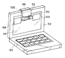
ここで図8に示すような、ディスプレイ62の上部62AにPCカードスロット66が設けられたノートブック型パソコン60であれば、カメラ台52にPCカード型の取付け部52Eを設け、その取付け部52EをPCカードスロット66に挿入することで、PCカメラ50を画面64内に配置することもできる。この場合、PCカメラ50とノートブック型パソコン60の接続が、ケーブルレスで簡単になる。
【0082】
【発明の効果】
本発明の撮像機器及び画像表示機器は上記構成としたので、TV会議等をパソコンで行う際に、被写体となる自分を撮像するときの画角合わせが容易になり、会話をする上で被写体の画像が自然な状態に撮像でき、且つそのときの撮像状態が被写体本人にも確認できる。
【図面の簡単な説明】
【図1】 本発明の第1の実施の形態に係る撮像機器を示す斜視図である。
【図2】 本発明の第1の実施の形態に係る撮像機器を示す側面図である。
【図3】 本発明の第2の実施の形態に係る撮像機器のブロック図である。
【図4】 本発明の第3の実施の形態に係る画像表示機器を示す斜視図である。
【図5】 本発明の第3の実施の形態に係る画像表示機器を示す側面図である。
【図6】 本発明の第3の実施の形態に係る画像表示機器に設けられた撮像機器の可動機構を示す拡大斜視図である。
【図7】 本発明の第3の実施の形態に係る画像表示機器に設けられた撮像機器の可動機構を示す拡大斜視図である。
【図8】 本発明の第3の実施の形態に係る画像表示機器の変形例を示す斜視図である。
【図9】 従来の撮像機器及び画像表示機器を示す斜視図である。
【図10】 従来の撮像機器及び画像表示機器を示す側面図である。
【符号の説明】
10 PCカメラ(撮像機器)
10A レンズ
14 ディスプレイ(画像表示機器)
16 画面
16A 画像
18 人物(被写体)
18A 目
20 平面鏡
20A 鏡面
30 PCカメラ(撮像機器)
32 フォーカシングセンサ(距離計測手段)
34 CPU(駆動制御手段)
36 駆動回路(駆動制御手段)
40 回動機構(駆動制御手段)
42 撮像デバイス(距離計測手段)
50 PCカメラ(撮像機器/撮像部)
52 カメラ台(可動機構を有する支持部)
52A アーム部
52B 取付け部
52C 回動部(回動機構)
52D スライド機構
62 ディスプレイ(画像表示機器)
64 画面
I 視線
L 光軸
M 面(レンズの光軸と直交する面)[0001]
BACKGROUND OF THE INVENTION
The present invention relates to an imaging device for capturing an image to be transmitted to a communication partner, and an image display device for displaying the image, which are provided in a personal computer that performs a TV conference or the like.
[0002]
[Prior art]
In general, personal computers (hereinafter simply referred to as “PCs”) are connected to various networks formed by cable lines such as telephone lines, LANs, or communication satellites so that persons who are in remote locations can communicate with each other. In a TV conference system in which conversations and conferences are performed by data communication of each other's images and sounds, a PC camera (imaging device) for capturing an image of the user to be transmitted to a communication partner is provided on the upper part of a display (image display device). The method is known.
[0003]
Other methods for attaching the PC camera to the personal computer include a method for attaching to the upper end of the display of a notebook personal computer (Japanese Patent Laid-Open No. 9-128091), and the PC camera body portion of the PC card type is connected to the PC card slot of the personal computer. There has also been proposed a method (Japanese Patent Laid-Open No. 8-130702) for transmitting image data inserted into, attached to, and captured to a personal computer.
[0004]
9 and 10 show a PC camera attached to the upper part of the display of a personal computer used in the TV conference system as described above.
[0005]
The
[0006]
The
[0007]
The
[0008]
With such a system, the
[0009]
Here, if the communication partner using the same system is connected to the line, the
[0010]
Furthermore, by using a microphone or a speaker (both not shown) connected (or built-in) to a personal computer, audio can be transmitted together with an image. With such a TV conference system using a personal computer, both communicating parties can perform a conversation or a conference through the other party's images and voices transmitted in almost real time.
[0011]
[Problems to be solved by the invention]
However, in the PC camera configured as described above, since the PC camera is arranged away from the image display position in the screen, it is not easy to adjust the angle of view for capturing the subject himself at an appropriate position in the image. It was.
[0012]
That is, as shown in FIG. 10, since there is a large opening (angle difference) between the line of sight I1 when the
[0013]
Furthermore, when viewing the
[0014]
On the other hand, at the time of a TV conference, since it is performed while viewing the image of the other party displayed on the normal screen, both face images obtained by imaging from diagonally upward. Such a conversation talking to the other party of the image is extremely unnatural compared to a normal conversation in which the other person's face is discussed.
[0015]
Here, in order to show the other person natural (facing the front), his eyes and face can be directed to the
[0016]
In consideration of the above facts, the present invention makes it easy to adjust the angle of view when taking a picture of yourself as a subject when conducting a TV conference or the like on a personal computer, so that the subject image is in a natural state for conversation. It is an object of the present invention to provide an imaging device and an image display device that can capture an image and can confirm the imaging state at that time also to the subject.
[0017]
[Means for Solving the Problems]
The configuration of the imaging device according to claim 1 is to use an image display device that is communicably connected via a communication unit, and to perform data communication between the communicating parties and display on the screen of the image display device. In the imaging device that captures the image of the correspondent who transmits to the communication partner, the imaging device includes an attachment portion that is attached to a surface other than the screen of the image display device, and a proximal end side through the rotation mechanism. An arm unit coupled to the mounting unit; and an imaging unit provided on a distal end side of the arm unit, and the imaging unit is disposed in the screen of the image display device by the rotation of the arm unit. The imaging direction of the imaging unit is movable between a use position in front of the screen and a retracted position that is rotated and retracted to the attachment unit side,The attachment portion is attached to the upper surface of the image display device, and when the imaging unit is retracted to the attachment unit side, the arm portion is placed on the attachment portion and the imaging unit faces downward. And
Further, as another example of means for solving the problem, for example, a configuration according to a first modification to a twelfth modification shown below can be employed.
The imaging device according to the first modified example uses an image display device that is communicably connected via a communication unit, and performs data communication between the communicating parties to display the image on the screen of the image display device. A mirror is provided that captures a subject image that is substantially the same as the subject image to be captured.
[0018]
Thus, by changing the orientation of the imaging device so that the subject's own face appears in the center of the mirror, the user's face is positioned at the center of the image to be captured. At this time, it is not necessary to view the image on the screen. In other words, it is only necessary to operate the imaging device while looking only at the mirror.
[0019]
Furthermore, mirrors are the most common tool for viewing one's own figure, and their usage is naturally known. For example, when you look at your face using a hand mirror, you can usually point your hand mirror at the part and direction you want to see. This is especially true when moving or tilting the mirror to the left or right, as the movement of the mirrored image appears to match the movement of the mirror, so how do you move the mirror relative to the image you want to see? Sometimes I don't think about it right or wrong.
[0020]
Similarly, the operation of the image pickup device for aligning his / her face with the center of the mirror provided in the image pickup device is easy to understand because the operation in the left / right direction can be performed as desired as described above. Therefore, these make it easy to adjust the angle of view of the imaging device.
[0021]
Furthermore, when you want to show your partner's natural facial expression (an image facing the front), if you point your face to the imaging device, your mirror will be reflected in the mirror provided on the imaging device. You can confirm your image as seen by the other party by moving the line of sight of the face.
[0022]
The imaging device according to the second modification isThe mirror surface is disposed so as to be inclined toward the subject with respect to a surface orthogonal to the optical axis of the lens of the imaging device. The inclination angle is substantially the same as the angle formed by the line of sight when the center of the mirror is viewed from the center of the mirror when the eye of the correspondent who is the subject is located almost on the optical axis. Is set to
[0023]
As a result, the eye is positioned at the center of the image captured by the imaging device and the mirror, the positional deviation of the subject image in the image with respect to the subject image of the mirror viewed from the subject is reduced, and the angle of view adjustment performed by looking at the mirror is reduced. Become more accurate.
[0024]
The imaging device according to the third modified example isDistance measuring means for measuring the distance to the subject and drive control means for directing the mirror surface of the mirror in the direction of the subject based on distance information from the subject measured by the distance measuring means.
[0025]
As a result, after the angle of view of the imaging device is adjusted to the subject, the subject moves slightly back and forth without shifting from the vicinity of the center of the image (on the optical axis of the lens) of the image captured by changing the posture of the subject. In this case, the distance measuring unit measures the distance between the imaging device and the subject, that is, the moving distance of the subject. The direction of the mirror surface of the mirror is directed toward the subject by the drive control means that operates based on this distance information.
[0026]
In this way, the mirror is directed in the direction of the subject in accordance with the movement of the subject, so that even if the subject moves as described above, it is possible to see his / her face reflected in the mirror.
[0027]
The imaging device according to the fourth modified example has the configuration of any one of the first modified example to the third modified example,The mirror is a convex mirror.
[0028]
Since a convex mirror has a larger angle of view (a range in which a subject is captured) than a plane mirror of the same size, the mirror can be made smaller than a plane mirror that can capture a subject of the same size or range.
[0029]
The imaging device according to the fifth modification isAn image display device connected to be communicable through a communication means is used, and in order to display data on the screen of the image display device by communicating the images of the communicators with each other, the image of the communicator himself to be transmitted to the communication partner is displayed. In the imaging device for imaging, the imaging device is disposed on an upper surface of the image display device, and an imaging unit provided in the imaging device is supported by a support unit having a movable mechanism and is suspended from an upper part of the image display device. It is possible to move between a use position arranged in the screen and a retracted position retracted on the upper surface side of the image display device.
[0030]
The imaging device according to the sixth modification isAn image display device connected to be communicable through a communication means is used, and in order to display data on the screen of the image display device by communicating the images of the communicators with each other, the image of the communicator himself to be transmitted to the communication partner is displayed. In the imaging device for imaging, the imaging device includes an attachment portion attached to a surface excluding the screen of the image display device, an arm portion having a proximal end connected to the attachment portion via a movable mechanism, and the arm portion An image pickup unit provided on the distal end side of the image display unit, and a use position where the image pickup unit is arranged in the screen of the image display device by the movement of the arm unit, and a retreat position retracted to the attachment unit side It is possible to move between and.
[0031]
The imaging device according to the seventh modification is the imaging device of the sixth modification,It is a rotation mechanism which makes the said arm part rotatable with respect to the said attachment part, It is characterized by the above-mentioned.
[0032]
The imaging device according to the eighth modification is the imaging device according to the sixth modification.The movable mechanism is a slide mechanism that allows the arm portion to rotate and slide with respect to the attachment portion.
[0033]
The imaging device according to the ninth modification is the imaging device of the sixth modification or the seventh modification.The arm part is provided with a telescopic mechanism, and the imaging part is slidable within the screen.
[0034]
The imaging device according to the tenth modification is the imaging device according to any one of the sixth to ninth modifications,The attachment portion is attached to the upper surface of the image display device, and when the imaging portion is retracted to the attachment portion side, at least the arm portion is placed on the attachment portion.
[0035]
The imaging device according to the eleventh modification is the imaging device according to any one of the sixth to ninth modifications,When the imaging unit is retracted to the attachment part side, at least the arm part is stored in the attachment part.
[0036]
According to the twelfth modificationThe image display device is communicably connected via a communication means, and an image of a communication person himself / herself transmitted by data communication to a communication partner is picked up by the image pickup device. It is displayed on the screen and is used to capture the image displayed on the screen.As described in any one of the first modification to the eleventh modificationAn imaging device is provided, and an imaging unit of the imaging device is arranged in the screen of the image display device.
[0037]
For this reason, the image of your face looking at the screen is placed in the screen.PartThe image is picked up almost from the front. Therefore, a natural image of the person facing the front is captured while keeping the line of sight or posture while looking at the screen. Further, when the subject is located in front of the screen, it is not necessary to adjust the angle of view.
[0038]
DETAILED DESCRIPTION OF THE INVENTION
Embodiments of the present invention will be described below with reference to the drawings.
[0039]
(First embodiment)
1 and 2 show a
[0040]
A
[0041]
A
[0042]
Here, the
[0043]
θ2 or θ1 is obtained by calculation based on the distance L1 from the center of the lens 10A to the eye 18A on the optical axis L and the distance N between the center of the lens 10A and the center of the plane mirror 20 (θ2 = Tan).-1N / L1).
[0044]
When the distance N = 8 cm and the distance L1 = about 80 cm as a result of the measurement, θ2 is about 5.7 °, and θ1 = 5.7 ° may be set. Incidentally, when the distance L1 is about 50 cm and about 100 cm, θ2 is about 9.1 ° and about 4.6 °.
[0045]
Various methods for setting θ1 are conceivable, but in order to realize a simple structure, a method of providing a scale so that the rotation angle with respect to the
[0046]
The
[0047]
As a result, the
[0048]
Thus, the
[0049]
As a result, by changing the orientation of the
[0050]
At this time, it is not necessary to look at the
[0051]
Furthermore, when the
[0052]
(Second Embodiment)
Next, a second embodiment of the present invention will be described. In this second embodiment, since it is almost the same as the configuration described in the first embodiment, the same components are denoted by the same reference numerals, and the description of the configuration is omitted.
[0053]
The feature of the second embodiment relates to a method of rotating the plane mirror provided in the PC camera.AhThis will be mainly described with reference to a block diagram.
[0054]
FIG. 3 is a block diagram of a
[0055]
The
[0056]
On the other hand, an
[0057]
As a result, at the time of imaging of the
[0058]
This image signal is subjected to signal processing by the analog
[0059]
Here, the
[0060]
Further, after the angle of view of the
[0061]
A signal is sent from the
[0062]
In this way, the
[0063]
Here, the focusing sensor is used for automatic focusing. However, it is also possible to obtain distance information with respect to the subject from the output of the
[0064]
In the PC camera according to the first embodiment and the first embodiment, the mirror is a rectangular plane mirror and is provided above the lens of the PC camera. However, the shape and type of the mirror and the mounting position are not limited to these.
[0065]
The external shape of the mirror can be a circle or an ellipse in addition to the rectangle. In particular, by matching the shape to the shape of the PC camera or the lens (in the first and the present embodiments, the PC camera is a substantially cylindrical body, so that it is a circle of substantially the same size), the lens is mirrored when not using the PC camera. It is also possible to turn the mirror so as to close it and use it as a lens cover.
[0066]
Moreover, the kind of mirror can also be a convex mirror other than a plane mirror. In this case, the size of the mirror can be reduced compared to a plane mirror that can capture a subject of the same size or range.
[0067]
Further, the mirror can be attached to the side of the lens other than the upper side of the lens. Even in such a case, the same effect can be obtained when the angle of view is adjusted by inclining the mirror toward the subject as described above.
[0068]
Furthermore, in the first embodiment, the rotation operation for adjusting the angle of view by the PC camera according to the present embodiment has been described as being based on a method of moving by hand. However, the present invention can also be used for a system in which a turning mechanism provided in a PC camera is operated by a remote controller.
[0069]
(Third embodiment)
Next, a third embodiment of the present invention will be described. In the third embodiment, since it is almost the same as the configuration described in the first embodiment, the same components are denoted by the same reference numerals, and the description of the configuration is omitted.
[0070]
The third embodiment relates to a display provided with a PC camera, and the feature relates to the arrangement of the PC camera.
[0071]
4 and 5 show the
[0072]
The substantially
[0073]
Further, on the
[0074]
As a result, the
[0075]
Here, when the personal computer is used for purposes other than the TV conference, that is, when the PC camera is not used, the display of the
[0076]
Therefore, this can be dealt with by making the connecting portion between the
[0077]
In the display according to the present embodiment, the PC camera is fixed to a substantially L-shaped camera base, and the PC camera is arranged in the screen by attaching the camera base to the upper surface of the display. However, the arrangement method and position of the PC camera on the screen are not limited to this.
[0078]
It is also possible to provide an expansion / contraction mechanism on the arm part of the camera base so that the PC camera can be slid in the vertical direction so that the image can be easily seen, or the camera base can be attached to the side surface or bottom surface of the display.
[0079]
Furthermore, if the display screen is made of glass such as a CRT type, a sucker-like member made of an elastic material such as rubber is provided on the back of the PC camera, and the PC camera is placed at an arbitrary position on the screen by the member. It is also possible to attach it by adsorption.
[0080]
Furthermore, the display according to the present embodiment is a single CRT type display used for a tower type (or desktop type) personal computer. However, the type of display is not limited to this. Similarly, a PC camera can be arranged on a single liquid crystal display or a notebook PC display.
[0081]
Here, in the notebook type
[0082]
【The invention's effect】
Since the imaging device and the image display device of the present invention have the above-described configuration, when a video conference or the like is performed on a personal computer, it is easy to adjust the angle of view when capturing an image of the subject as a subject. The image can be captured in a natural state, and the imaging state at that time can be confirmed by the subject himself / herself.
[Brief description of the drawings]
FIG. 1 is a perspective view showing an imaging device according to a first embodiment of the present invention.
FIG. 2 is a side view showing the imaging device according to the first embodiment of the present invention.
FIG. 3 is a block diagram of an imaging device according to a second embodiment of the present invention.
FIG. 4 is a perspective view showing an image display device according to a third embodiment of the present invention.
FIG. 5 is a side view showing an image display device according to a third embodiment of the present invention.
FIG. 6 is an enlarged perspective view showing a movable mechanism of an imaging device provided in an image display device according to a third embodiment of the present invention.
FIG. 7 is an enlarged perspective view showing a movable mechanism of an imaging device provided in an image display device according to a third embodiment of the present invention.
FIG. 8 is a perspective view showing a modification of the image display device according to the third embodiment of the present invention.
FIG. 9 is a perspective view showing a conventional imaging device and image display device.
FIG. 10 is a side view showing a conventional imaging device and image display device.
[Explanation of symbols]
10 PC camera (imaging equipment)
10A lens
14 Display (image display device)
16 screens
16A image
18 Person (Subject)
18A eyes
20 Plane mirror
20A Mirror surface
30 PC camera (imaging equipment)
32 Focusing sensor (distance measuring means)
34 CPU (drive control means)
36 Drive circuit (drive control means)
40 Rotating mechanism (drive control means)
42 Imaging device (distance measuring means)
50 PC camera (imaging equipment)/ Imaging unit)
52 Camera stand (supporting part having movable mechanism)
52A Arm
52B Mounting part
52C Rotating part (Rotating mechanism)
52D slide mechanism
62 Display (image display device)
64 screens
I eyes
L Optical axis
M surface (surface orthogonal to the optical axis of the lens)
Claims (1)
前記撮像機器は、
前記画像表示機器の前記画面を除く表面に取付けられる取付け部と、
基端側が回動機構を介して前記取付け部に連結されたアーム部と、
前記アーム部の先端側に設けられた撮像部と、
を有し、
前記撮像部が前記アーム部の回動により、画像表示機器の前記画面内に配置され、前記撮像部の撮影可能な方向が前記画面の前方である使用位置と、前記取付け部側に回動して退避した退避位置と、の間で移動可能とされ、
前記取付け部が前記画像表示機器の上面に取付けられ、
前記撮像部が前記取付け部側に退避すると、前記アーム部が前記取付け部上に載置されると共に前記撮像部が下方を向くことを特徴とする撮像機器。 An image display device connected to be communicable through a communication means is used, and in order to display data on the screen of the image display device by communicating the images of the communicators with each other, the image of the communicator himself to be transmitted to the communication partner is displayed. In imaging equipment that captures images,
The imaging device is
An attachment portion that is attached to a surface of the image display device other than the screen;
An arm portion having a base end connected to the mounting portion via a rotation mechanism;
An imaging unit provided on the distal end side of the arm unit;
Have
The imaging unit is arranged in the screen of the image display device by the rotation of the arm unit, and the imaging direction of the imaging unit is rotated to the use position in front of the screen and the mounting unit side. It is possible to move between the retracted position and
The attachment portion is attached to the upper surface of the image display device;
When the imaging unit is retracted to the mounting unit side, the arm unit is placed on the mounting unit and the imaging unit faces downward.
Priority Applications (1)
| Application Number | Priority Date | Filing Date | Title |
|---|---|---|---|
| JP01609599A JP4390887B2 (en) | 1999-01-25 | 1999-01-25 | Imaging equipment |
Applications Claiming Priority (1)
| Application Number | Priority Date | Filing Date | Title |
|---|---|---|---|
| JP01609599A JP4390887B2 (en) | 1999-01-25 | 1999-01-25 | Imaging equipment |
Publications (3)
| Publication Number | Publication Date |
|---|---|
| JP2000214517A JP2000214517A (en) | 2000-08-04 |
| JP2000214517A5 JP2000214517A5 (en) | 2006-03-30 |
| JP4390887B2 true JP4390887B2 (en) | 2009-12-24 |
Family
ID=11906969
Family Applications (1)
| Application Number | Title | Priority Date | Filing Date |
|---|---|---|---|
| JP01609599A Expired - Fee Related JP4390887B2 (en) | 1999-01-25 | 1999-01-25 | Imaging equipment |
Country Status (1)
| Country | Link |
|---|---|
| JP (1) | JP4390887B2 (en) |
Families Citing this family (7)
| Publication number | Priority date | Publication date | Assignee | Title |
|---|---|---|---|---|
| JP4809624B2 (en) * | 2005-04-21 | 2011-11-09 | 彌吉郎 酒井 | Video conference system |
| US7728906B2 (en) | 2006-01-04 | 2010-06-01 | Apple Inc. | Embedded camera with privacy filter |
| KR102146025B1 (en) * | 2011-12-30 | 2020-08-20 | 삼성전자주식회사 | Display apparatus |
| US8867015B2 (en) | 2012-01-11 | 2014-10-21 | Apple Inc. | Displays with liquid crystal shutters |
| JP2013178702A (en) * | 2012-02-29 | 2013-09-09 | Azbil Corp | Face authentication sensor |
| KR102100184B1 (en) * | 2013-02-18 | 2020-04-13 | 삼성전자주식회사 | Display apparatus |
| AT514520B1 (en) * | 2013-07-04 | 2015-04-15 | Friedrich Dipl Ing Scherübel | Method for ergonomically correct adjustment of a screen and set to carry out the same |
-
1999
- 1999-01-25 JP JP01609599A patent/JP4390887B2/en not_active Expired - Fee Related
Also Published As
| Publication number | Publication date |
|---|---|
| JP2000214517A (en) | 2000-08-04 |
Similar Documents
| Publication | Publication Date | Title |
|---|---|---|
| US10331024B2 (en) | Mobile and portable screen to view an image recorded by a camera | |
| US10831093B1 (en) | Focus control for a plurality of cameras in a smartphone | |
| FI111892B (en) | Multifunction messaging device | |
| US20080239061A1 (en) | First portable communication device | |
| US7822338B2 (en) | Camera for electronic device | |
| JP3950399B2 (en) | Image stabilization device for micro camera module of handheld device and method for stabilizing micro camera module of handheld device | |
| EP1793599A1 (en) | Electronic device | |
| US20180234635A1 (en) | Imaging system and imaging control method | |
| JP2001522063A (en) | Eyeglass interface system | |
| US10261408B2 (en) | Mobile and portable camera platform for tracking an object | |
| US20200348627A1 (en) | Wrist-Worn Device with One or More Cameras and a Comfortable Arm Posture During Imaging | |
| CN106664361B (en) | Information processing apparatus, information processing method, and computer-readable storage medium | |
| JP4390887B2 (en) | Imaging equipment | |
| JP6074894B2 (en) | Information display device | |
| US20050128347A1 (en) | Tripod of image photographing apparatus | |
| JP2000214517A5 (en) | ||
| JP2004274777A (en) | Portable multifunctional electronic apparatus | |
| JP2013174730A (en) | Information display device | |
| JPH0898076A (en) | Image input device | |
| JP2002218292A (en) | Mobile information communication terminal with camera function | |
| JPH0964777A (en) | Radio video signal transmitter-receiver | |
| JP2005020187A (en) | Stereoscopic image photographing apparatus, and electronic apparatus provided with stereoscopic image photographing apparatus | |
| JP2005250396A (en) | Personal digital assistant with camera | |
| KR200261399Y1 (en) | Computer communication camera with the Viewfinder/Moniter | |
| EP2053444A1 (en) | Optical system |
Legal Events
| Date | Code | Title | Description |
|---|---|---|---|
| A521 | Request for written amendment filed |
Free format text: JAPANESE INTERMEDIATE CODE: A523 Effective date: 20060125 |
|
| A621 | Written request for application examination |
Free format text: JAPANESE INTERMEDIATE CODE: A621 Effective date: 20060125 |
|
| A711 | Notification of change in applicant |
Free format text: JAPANESE INTERMEDIATE CODE: A712 Effective date: 20070105 |
|
| A977 | Report on retrieval |
Free format text: JAPANESE INTERMEDIATE CODE: A971007 Effective date: 20090401 |
|
| A131 | Notification of reasons for refusal |
Free format text: JAPANESE INTERMEDIATE CODE: A131 Effective date: 20090428 |
|
| A521 | Request for written amendment filed |
Free format text: JAPANESE INTERMEDIATE CODE: A523 Effective date: 20090615 |
|
| A131 | Notification of reasons for refusal |
Free format text: JAPANESE INTERMEDIATE CODE: A131 Effective date: 20090714 |
|
| A521 | Request for written amendment filed |
Free format text: JAPANESE INTERMEDIATE CODE: A523 Effective date: 20090826 |
|
| TRDD | Decision of grant or rejection written | ||
| A01 | Written decision to grant a patent or to grant a registration (utility model) |
Free format text: JAPANESE INTERMEDIATE CODE: A01 Effective date: 20090929 |
|
| A01 | Written decision to grant a patent or to grant a registration (utility model) |
Free format text: JAPANESE INTERMEDIATE CODE: A01 |
|
| A61 | First payment of annual fees (during grant procedure) |
Free format text: JAPANESE INTERMEDIATE CODE: A61 Effective date: 20091007 |
|
| FPAY | Renewal fee payment (event date is renewal date of database) |
Free format text: PAYMENT UNTIL: 20121016 Year of fee payment: 3 |
|
| R150 | Certificate of patent or registration of utility model |
Free format text: JAPANESE INTERMEDIATE CODE: R150 |
|
| FPAY | Renewal fee payment (event date is renewal date of database) |
Free format text: PAYMENT UNTIL: 20121016 Year of fee payment: 3 |
|
| FPAY | Renewal fee payment (event date is renewal date of database) |
Free format text: PAYMENT UNTIL: 20131016 Year of fee payment: 4 |
|
| LAPS | Cancellation because of no payment of annual fees |