JP4388057B2 - Developer container, image forming unit, and image forming apparatus - Google Patents
Developer container, image forming unit, and image forming apparatus Download PDFInfo
- Publication number
- JP4388057B2 JP4388057B2 JP2006292575A JP2006292575A JP4388057B2 JP 4388057 B2 JP4388057 B2 JP 4388057B2 JP 2006292575 A JP2006292575 A JP 2006292575A JP 2006292575 A JP2006292575 A JP 2006292575A JP 4388057 B2 JP4388057 B2 JP 4388057B2
- Authority
- JP
- Japan
- Prior art keywords
- developer
- supply port
- developer container
- opening
- closing member
- Prior art date
- Legal status (The legal status is an assumption and is not a legal conclusion. Google has not performed a legal analysis and makes no representation as to the accuracy of the status listed.)
- Active
Links
Images


Classifications
-
- G—PHYSICS
- G03—PHOTOGRAPHY; CINEMATOGRAPHY; ANALOGOUS TECHNIQUES USING WAVES OTHER THAN OPTICAL WAVES; ELECTROGRAPHY; HOLOGRAPHY
- G03G—ELECTROGRAPHY; ELECTROPHOTOGRAPHY; MAGNETOGRAPHY
- G03G15/00—Apparatus for electrographic processes using a charge pattern
- G03G15/06—Apparatus for electrographic processes using a charge pattern for developing
- G03G15/08—Apparatus for electrographic processes using a charge pattern for developing using a solid developer, e.g. powder developer
- G03G15/0822—Arrangements for preparing, mixing, supplying or dispensing developer
- G03G15/0877—Arrangements for metering and dispensing developer from a developer cartridge into the development unit
- G03G15/0881—Sealing of developer cartridges
- G03G15/0886—Sealing of developer cartridges by mechanical means, e.g. shutter, plug
-
- G—PHYSICS
- G03—PHOTOGRAPHY; CINEMATOGRAPHY; ANALOGOUS TECHNIQUES USING WAVES OTHER THAN OPTICAL WAVES; ELECTROGRAPHY; HOLOGRAPHY
- G03G—ELECTROGRAPHY; ELECTROPHOTOGRAPHY; MAGNETOGRAPHY
- G03G15/00—Apparatus for electrographic processes using a charge pattern
- G03G15/06—Apparatus for electrographic processes using a charge pattern for developing
- G03G15/08—Apparatus for electrographic processes using a charge pattern for developing using a solid developer, e.g. powder developer
- G03G15/0822—Arrangements for preparing, mixing, supplying or dispensing developer
- G03G15/0848—Arrangements for testing or measuring developer properties or quality, e.g. charge, size, flowability
- G03G15/0849—Detection or control means for the developer concentration
- G03G15/0855—Detection or control means for the developer concentration the concentration being measured by optical means
-
- G—PHYSICS
- G03—PHOTOGRAPHY; CINEMATOGRAPHY; ANALOGOUS TECHNIQUES USING WAVES OTHER THAN OPTICAL WAVES; ELECTROGRAPHY; HOLOGRAPHY
- G03G—ELECTROGRAPHY; ELECTROPHOTOGRAPHY; MAGNETOGRAPHY
- G03G15/00—Apparatus for electrographic processes using a charge pattern
- G03G15/06—Apparatus for electrographic processes using a charge pattern for developing
- G03G15/08—Apparatus for electrographic processes using a charge pattern for developing using a solid developer, e.g. powder developer
- G03G15/0822—Arrangements for preparing, mixing, supplying or dispensing developer
- G03G15/0865—Arrangements for supplying new developer
-
- G—PHYSICS
- G03—PHOTOGRAPHY; CINEMATOGRAPHY; ANALOGOUS TECHNIQUES USING WAVES OTHER THAN OPTICAL WAVES; ELECTROGRAPHY; HOLOGRAPHY
- G03G—ELECTROGRAPHY; ELECTROPHOTOGRAPHY; MAGNETOGRAPHY
- G03G2215/00—Apparatus for electrophotographic processes
- G03G2215/06—Developing structures, details
- G03G2215/066—Toner cartridge or other attachable and detachable container for supplying developer material to replace the used material
- G03G2215/0663—Toner cartridge or other attachable and detachable container for supplying developer material to replace the used material having a longitudinal rotational axis, around which at least one part is rotated when mounting or using the cartridge
- G03G2215/0665—Generally horizontally mounting of said toner cartridge parallel to its longitudinal rotational axis
- G03G2215/067—Toner discharging opening covered by arcuate shutter
-
- G—PHYSICS
- G03—PHOTOGRAPHY; CINEMATOGRAPHY; ANALOGOUS TECHNIQUES USING WAVES OTHER THAN OPTICAL WAVES; ELECTROGRAPHY; HOLOGRAPHY
- G03G—ELECTROGRAPHY; ELECTROPHOTOGRAPHY; MAGNETOGRAPHY
- G03G2215/00—Apparatus for electrophotographic processes
- G03G2215/06—Developing structures, details
- G03G2215/066—Toner cartridge or other attachable and detachable container for supplying developer material to replace the used material
- G03G2215/0692—Toner cartridge or other attachable and detachable container for supplying developer material to replace the used material using a slidable sealing member, e.g. shutter
Description
本発明は、現像剤収容器、画像形成ユニット及び画像形成装置に関するものである。 The present invention relates to a developer container, an image forming unit, and an image forming apparatus.
従来、電子写真式のプリンタ、複写機、ファクシミリ装置、複合機等の画像形成装置、例えば、プリンタにおいては、画像形成ユニットが配設され、該画像形成ユニットに感光体ドラム、帯電ローラ、現像器等が配設される。そして、帯電ローラによって一様に、かつ、均一に帯電させられた感光体ドラムの表面をLEDヘッドによって露光して静電潜像を形成し、該静電潜像を現像器によって現像してトナー像を形成し、該トナー像を転写ローラによって用紙に転写し、定着器によって定着させることにより、画像を形成し、印刷を行うようになっている。 2. Description of the Related Art Conventionally, in an image forming apparatus such as an electrophotographic printer, a copying machine, a facsimile machine, and a multifunction machine, for example, a printer, an image forming unit is provided, and a photosensitive drum, a charging roller, and a developing device are provided in the image forming unit. Etc. are arranged. Then, the surface of the photosensitive drum uniformly and uniformly charged by the charging roller is exposed by an LED head to form an electrostatic latent image, and the electrostatic latent image is developed by a developing device to form a toner. An image is formed, the toner image is transferred onto a sheet by a transfer roller, and fixed by a fixing device, thereby forming an image and printing.
ところで、前記画像形成ユニットにおいては、現像剤収容器としてのトナーカートリッジが着脱自在に配設され、該トナーカートリッジから前記現像器にトナーが供給される。そのために、トナーカートリッジの下面にトナー供給口が形成され、該トナー供給口を開閉するために、シャッタが配設される。該シャッタには開口部が形成され、シャッタと一体に形成された操作レバーを回動させ、前記トナー供給口と開口部とを合わせることによって、トナー供給口を開放することができる(例えば、特許文献1参照。)。
しかしながら、前記従来のトナーカートリッジにおいては、画像形成ユニットの本体、すなわち、画像形成ユニット本体に対して未装着の状態において、トナー供給口を上方に向けたまま開閉させることができるので、不用意にシャッタを開放すると、トナーカートリッジ内に異物が混入してしまうことがある。 However, in the conventional toner cartridge, the toner supply port can be opened and closed with the image forming unit main body, that is, the image forming unit main body not attached to the main body. When the shutter is opened, foreign matter may enter the toner cartridge.
本発明は、前記従来のトナーカートリッジの問題点を解決して、現像剤収容器に異物が混入するのを防止することができる現像剤収容器、画像形成ユニット及び画像形成装置を提供することを目的とする。 The present invention provides a developer container, an image forming unit, and an image forming apparatus capable of solving the problems of the conventional toner cartridge and preventing foreign matter from entering the developer container. Objective.
そのために、本発明の現像剤収容器においては、現像剤供給口が形成された現像剤収容体と、該現像剤収容体に対して移動自在に配設され、移動に伴って、前記現像剤供給口を開閉する開閉部材と、該開閉部材を移動させるための操作部と、前記現像剤供給口の向きに応じて前記開閉部材の回動を阻止又は許容する回動規制部材とを有する。
そして、該回動規制部材は、前記現像剤収容体及び操作部のうちの一方に形成された係止部と係脱させられる係合部を備え、現像剤収容体の前記現像剤供給口を上方に向けたときに、前記係止部と前記係合部とが係合させられて前記開閉部材の回動を阻止し、現像剤収容体の前記現像剤供給口を下方に向けたときに、前記係止部と前記係合部との係合が解除されて前記開閉部材の回動を許容する。
For this purpose, in the developer container of the present invention, the developer container having a developer supply port formed therein, and the developer container is movably disposed with respect to the developer container. An opening / closing member that opens and closes the supply port; an operation unit that moves the opening / closing member; and a rotation restricting member that prevents or allows rotation of the opening / closing member depending on the direction of the developer supply port.
The rotation restricting member includes an engaging part that is engaged with and disengaged from a locking part formed on one of the developer container and the operation part, and the developer supply port of the developer container is provided. When the locking portion and the engaging portion are engaged with each other to prevent the rotation of the opening / closing member and the developer supply port of the developer container is directed downward. The engagement between the locking part and the engaging part is released, and the opening / closing member is allowed to rotate.
本発明によれば、現像剤収容器においては、現像剤供給口が形成された現像剤収容体と、該現像剤収容体に対して移動自在に配設され、移動に伴って、前記現像剤供給口を開閉する開閉部材と、該開閉部材を移動させるための操作部と、前記現像剤供給口の向きに応じて前記開閉部材の回動を阻止又は許容する回動規制部材とを有する。
そして、該回動規制部材は、前記現像剤収容体及び操作部のうちの一方に形成された係止部と係脱させられる係合部を備え、現像剤収容体の前記現像剤供給口を上方に向けたときに、前記係止部と前記係合部とが係合させられて前記開閉部材の回動を阻止し、現像剤収容体の前記現像剤供給口を下方に向けたときに、前記係止部と前記係合部との係合が解除されて前記開閉部材の回動を許容する。
According to the present invention, in the developer container, the developer container in which the developer supply port is formed and the developer container are movably disposed with respect to the developer container, and the developer is moved along with the movement. An opening / closing member that opens and closes the supply port; an operation unit that moves the opening / closing member; and a rotation restricting member that prevents or allows rotation of the opening / closing member depending on the direction of the developer supply port.
The rotation restricting member includes an engaging part that is engaged with and disengaged from a locking part formed on one of the developer container and the operation part, and the developer supply port of the developer container is provided. When the locking portion and the engaging portion are engaged with each other to prevent the rotation of the opening / closing member and the developer supply port of the developer container is directed downward. The engagement between the locking part and the engaging part is released, and the opening / closing member is allowed to rotate.
この場合、前記現像剤供給口の向きに応じて前記開閉部材の回動が阻止又は許容されるので、不用意に現像剤供給口が開くことがなくなる。したがって、現像剤収容器内に異物が混入するのを防止することができる。 In this case, since the opening / closing member is prevented or allowed to rotate according to the direction of the developer supply port, the developer supply port is not opened carelessly. Therefore, it is possible to prevent foreign matters from entering the developer container.
以下、本発明の実施の形態について図面を参照しながら詳細に説明する。この場合、画像形成装置としてのプリンタについて説明する。 Hereinafter, embodiments of the present invention will be described in detail with reference to the drawings. In this case, a printer as an image forming apparatus will be described.
図2は本発明の第1の実施の形態におけるプリンタの概略図である。 FIG. 2 is a schematic view of the printer according to the first embodiment of the present invention.
図に示されるように、プリンタの下部に媒体収容部としての給紙カセット11が配設され、該給紙カセット11内に記録媒体としての図示されない用紙が収容される。前記給紙カセット11の前端に隣接させて、用紙を1枚ずつ分離させて給紙するための給紙機構が配設される。該給紙機構は、給紙ローラ12及び分離ローラ13を備え、給紙機構によって給紙された用紙は、上方に配設された搬送ローラ14に送られ、更に搬送ローラ15に送られた後、ブラック、イエロー、マゼンタ及びシアンの各色の画像を形成する画像形成部としての画像形成ユニット16Bk、16Y、16M、16Cに供給される。
As shown in the drawing, a
該各画像形成ユニット16Bk、16Y、16M、16Cには、像担持体としての感光体ドラム31Bk、31Y、31M、31Cが配設され、該各感光体ドラム31Bk、31Y、31M、31Cの表面を露光して静電潜像を形成するための露光装置としてのLEDヘッド22Bk、22Y、22M、22Cが、各画像形成ユニット16Bk、16Y、16M、16Cに隣接させて、かつ、各感光体ドラム31Bk、31Y、31M、31Cと対向させて配設される。 The image forming units 16Bk, 16Y, 16M, and 16C are provided with photosensitive drums 31Bk, 31Y, 31M, and 31C as image carriers, and the surface of each of the photosensitive drums 31Bk, 31Y, 31M, and 31C is disposed. LED heads 22Bk, 22Y, 22M, and 22C as exposure devices for exposing to form an electrostatic latent image are adjacent to each image forming unit 16Bk, 16Y, 16M, and 16C, and each photosensitive drum 31Bk. , 31Y, 31M, and 31C.
また、前記各画像形成ユニット16Bk、16Y、16M、16Cに沿って、転写ユニットu1が配設され、該転写ユニットu1は、駆動ローラr1、従動ローラr2、前記駆動ローラr1と従動ローラr2との間に張設され、走行自在に配設された搬送部材としての搬送ベルト17、及び該搬送ベルト17を挟み、前記感光体ドラム31Bk、31Y、31M、31Cと対向させて配設された転写部材としての転写ローラ21Bk、21Y、21M、21Cを備える。
A transfer unit u1 is disposed along each of the image forming units 16Bk, 16Y, 16M, and 16C. The transfer unit u1 includes a driving roller r1, a driven roller r2, and the driving roller r1 and the driven roller r2. A
前記用紙は、前記搬送ベルト17が走行させられるのに伴って搬送され、画像形成ユニット16Bk、16Y、16M、16Cと転写ローラ21Bk、21Y、21M、21Cとの間を通過し、該各転写ローラ21Bk、21Y、21M、21Cは、各画像形成ユニット16Bk、16Y、16M、16Cにおいて形成された各色の現像剤像としてのトナー像を、用紙に順次重ねて転写し、カラーのトナー像を形成する。
The sheet is transported as the
続いて、用紙は、定着装置としての定着器18に送られ、該定着器18においてカラーのトナー像が用紙に定着させられ、カラーの画像が形成される。そして、定着器18から排出された用紙は、搬送ローラ19によって搬送された後、排出搬送ローラ20によってプリンタ外に排出される。
Subsequently, the paper is sent to a
次に、前記画像形成ユニット16Bk、16Y、16M、16Cについて説明する。なお、該画像形成ユニット16Bk、16Y、16M、16Cは、いずれも構造が同じであるので、画像形成ユニット16Bkについて説明し、画像形成ユニット16Y、16M、16Cについては、説明を省略する。
Next, the image forming units 16Bk, 16Y, 16M, and 16C will be described. Since the image forming units 16Bk, 16Y, 16M, and 16C have the same structure, the image forming unit 16Bk will be described, and the description of the
図3は本発明の第1の実施の形態における画像形成ユニットの配設された状態を示す断面図である。 FIG. 3 is a cross-sectional view showing a state in which the image forming unit is disposed in the first exemplary embodiment of the present invention.
図に示されるように、前記画像形成ユニット16Bkにおいて、画像形成ユニット本体37に対して、現像剤としてのトナーを収容した現像剤収容器としてのトナーカートリッジ41が着脱自在に配設され、該トナーカートリッジ41から前記画像形成ユニット本体37内に配設された現像器30にトナーが供給される。そのために、トナーカートリッジ41における現像剤収容体としてのケース43の下面に現像剤供給口としてのトナー供給口44が形成され、該トナー供給口44を開閉するために、開閉部材としてのシャッタ42が移動自在に、本実施の形態においては、回動自在に配設される。該シャッタ42には開口部42aが形成され、シャッタ42と一体に形成された操作部としての図示されない操作レバーを回動させ、シャッタ42を移動、本実施の形態においては、シャッタ42を回動させ、前記トナー供給口44と開口部42aとを合わせることによって、トナー供給口44を開放することができる。また、操作レバーを回動させ、シャッタ42を回動させ、前記トナー供給口44と開口部42aとをずらすことによって、トナー供給口44を閉鎖することができる。
As shown in the figure, in the image forming unit 16Bk, a
一方、画像形成ユニット本体37には、トナーカートリッジ41をセットするために、凹面から成る取付面が形成され、該取付面に前記トナー供給口44と対応させて現像剤補給口としてのトナー補給口45が形成される。したがって、トナー供給口44が開放されると、トナーカートリッジ41内のトナーがトナー補給口45を介して画像形成ユニット本体37内に供給される。
On the other hand, the image forming unit
ところで、画像形成ユニット16Bkは、感光体ドラム31Bk、該感光体ドラム31Bkの表面を一様に、かつ、均一に帯電させる帯電装置としての帯電ローラ32、トナーを保持する現像剤担持体としての現像ローラ33、該現像ローラ33にトナーを供給する現像剤供給部材としてのトナー供給ローラ34、前記現像ローラ33上に供給されたトナーを均一に薄層化する現像剤層規制部材としての現像ブレード35、及びトナー像の転写後に感光体ドラム31Bkに残留したトナーを除去するクリーニング装置としてのクリーニングブレード36を備える。
By the way, the image forming unit 16Bk has a photosensitive drum 31Bk, a
前記感光体ドラム31Bkは、アルミニウム等から成る導電性基層、及び有機感光体から成る表層によって形成され、帯電ローラ32は、導電性の金属シャフトにエピクロルヒドリンゴム等の半導電性のロール状のゴムを被覆して形成され、現像ローラ33は、導電性の金属シャフトにシリコーン等の半導電性のゴムを被覆して形成され、トナー供給ローラ34は、導電性の金属シャフトに、トナーの搬送性を向上させるために、混練時に、発泡剤を添加して形成されたゴムを被覆して形成される。
The photoconductive drum 31Bk is formed of a conductive base layer made of aluminum or the like and a surface layer made of an organic photoconductor, and the
前記帯電ローラ32、現像ローラ33及びクリーニングブレード36は前記感光体ドラム31Bkと接触させて配設され、前記トナー供給ローラ34及び現像ブレード35は現像ローラ33と接触させて配設される。また、図示されない現像ローラ用の電源、トナー供給ローラ用の電源及び現像ブレード用の電源がそれぞれ前記現像ローラ33、トナー供給ローラ34及び現像ブレード35と接続され、現像ローラ33、トナー供給ローラ34及び現像ブレード35にバイアス電圧を印加する。
The charging
前記構成のプリンタにおいて、印刷時に、前記現像ローラ33及びトナー供給ローラ34は、現像剤供給用の駆動部としての図示されない駆動モータによって、いずれも反時計回りに回転させられ、トナー供給ローラ34によって現像ローラ33にトナーが供給される。そして、前記現像ローラ33に供給されたトナーは、現像ローラ33の回転に伴って現像ローラ33と前記現像ブレード35との接触部に送られ、現像ブレード35によって余剰のトナーが掻き落とされ、薄層化され、その後、現像ローラ33の回転に伴って感光体ドラム31Bkに送られる。
In the printer having the above-described configuration, at the time of printing, the developing
一方、該感光体ドラム31Bkは、画像形成用の駆動部としての図示されないドラムモータを駆動するとによって所定の方向に回転させられ、感光体ドラム31Bkの回転に伴って、該感光体ドラム31Bkの表面は、帯電ローラ32によって一様に、かつ、均一に帯電させられ、LEDヘッド22Bkによって露光されて静電潜像が形成され、該静電潜像に前記現像ローラ33上のトナーが静電的に付着させられてトナー像が形成される。
On the other hand, the photosensitive drum 31Bk is rotated in a predetermined direction by driving a drum motor (not shown) as a drive unit for image formation, and the surface of the photosensitive drum 31Bk is rotated with the rotation of the photosensitive drum 31Bk. Is charged uniformly and uniformly by the charging
図1は本発明の第1の実施の形態におけるトナーカートリッジの分解斜視図、図4は本発明の第1の実施の形態におけるシャッタの取付状態を示す第1の図、図5は本発明の第1の実施の形態におけるシャッタの取付状態を示す第2の図である。 FIG. 1 is an exploded perspective view of the toner cartridge according to the first embodiment of the present invention, FIG. 4 is a first view showing a mounting state of the shutter according to the first embodiment of the present invention, and FIG. It is a 2nd figure which shows the attachment state of the shutter in 1st Embodiment.
図1において、41は現像剤収容器としてのトナーカートリッジであり、該トナーカートリッジ41において、内部にトナーを収容するためのケース43が配設され、該ケース43の下面にトナー供給口44が形成される。該トナー供給口44を開閉するためのシャッタ42は、トナー供給口44を閉鎖するための遮蔽部42c、及び前記トナー供給口44を開放するための開口部42aを有する。また、前記遮蔽部42cの外周面にはシール部材42dが貼付け等によって取り付けられ、トナー供給口44から未使用のトナーが外部に漏れ出すのを防止する。さらに、前記シャッタ42には操作部としての操作レバー42bが一体に形成される。そして、前記ケース43と操作レバー42bとの間には、操作レバー42bの回動を規制し、回動範囲を設定する規制部材46が配設される。
In FIG. 1,
なお、図4はトナー供給口を閉鎖した状態を、図5はトナー供給口を開放した状態を示す。 4 shows a state where the toner supply port is closed, and FIG. 5 shows a state where the toner supply port is opened.
この場合、前記規制部材46を押すとロックが解除され、操作レバー42bが回動可能になり、操作レバー42bを規制部材46に突き当たるまで回動することによってシャッタ42の開口部42aとトナー供給口44とが合わされ、トナー供給口44が開放される。
In this case, when the restricting
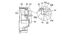
図6は本発明の第1の実施の形態におけるトナーカートリッジの要部を示す第1の断面図、図7は本発明の第1の実施の形態におけるトナーカートリッジの要部を示す第1の斜視図、図8は本発明の第1の実施の形態におけるトナーカートリッジの要部を示す第2の断面図、図9は本発明の第1の実施の形態におけるトナーカートリッジの要部を示す第2の斜視図である。 FIG. 6 is a first sectional view showing the main part of the toner cartridge according to the first embodiment of the present invention, and FIG. 7 is a first perspective view showing the main part of the toner cartridge according to the first embodiment of the present invention. 8 is a second cross-sectional view showing the main part of the toner cartridge according to the first embodiment of the present invention. FIG. 9 is a second cross-sectional view showing the main part of the toner cartridge according to the first embodiment of the present invention. FIG.
図に示されるように、ケース43には、トナー供給口44と隣接する部分の内周面に、所定の深さを有する係止部としての凹溝51が形成される。また、シャッタ42には、遮蔽部42cに貫通孔52が形成され、該貫通孔52は、トナー供給口44を閉鎖したときに、凹溝51と同じ位置になるように形成される。
As shown in the figure, the
そして、ほぼ「L」字状の形状を有する回動規制部材としての連結部材53が、シャッタ42に配設された軸受け部54によって揺動自在に支持され、連結位置及び解除位置を採る。前記連結部材53は、第1、第2のアーム53a、53bを備え、第1のアーム53aの先端に、前記貫通孔52を貫通して凹溝51と係合する係合部53cが形成され、第2のアーム53bの先端に錘部53dが形成され、前記連結部材53は自重によって揺動させられる。なお、前記第2のアーム53bにおける第1のアーム53aと近接する位置に揺動中心が置かれる。
Then, a connecting
次に、前記連結部材53の動作について説明する。
Next, the operation of the connecting
この場合、前記トナー供給口44の向きに応じて前記シャッタ42の回動が阻止又は許容される。すなわち、図6及び7に示されるように、前記トナーカートリッジ41を、トナー供給口44が上方に向くように置くと、連結部材53は、連結位置を採り、錘部53dが自重によって下方に下がり、それに伴って反対側の係合部53cが上方に持ち上がり、ケース43の凹溝51の底面に接触し、凹溝51及び貫通孔52と係合させられる。これにより、ケース43とシャッタ42とが連結されるので、シャッタ42の回動が阻止される。
In this case, the rotation of the
次に、図8及び9に示されるように、前記トナーカートリッジ41を、トナー供給口44が下方に向くように置くと、連結部材53は、解除位置を採り、錘部53dが自重によって下方に下がり、シャッタ42の内周面に接触し、係合部53cが上方に持ち上がり、ケース43の凹溝51と係合しなくなる。これにより、ケース43とシャッタ42との連結が解除されるので、シャッタ42の回動が許容される。
Next, as shown in FIGS. 8 and 9, when the
このように、本実施の形態においては、前記ケース43に凹溝51が、シャッタ42に貫通孔52が形成され、凹溝51及び貫通孔52と係脱自在に連結部材53が配設されるので、トナーカートリッジ41を、トナー供給口44が上方に向くように置くと、連結部材53によってケース43とシャッタ42とが連結され、シャッタ42を回動させることができなくなるので、不用意にトナー供給口44が開くことがなくなる。したがって、トナーカートリッジ41内に異物が混入するのを防止することができる。
Thus, in the present embodiment, the
また、該トナーカートリッジ41を、トナー供給口44が下方に向くように置くと、ケース43とシャッタ42との連結が解除され、シャッタ42を回動させることができるようになる。したがって、トナーカートリッジ41を使用することができる。
When the
次に、本発明の第2の実施の形態について説明する。なお、第1の実施の形態と同じ構造を有するものについては、同じ符号を付与することによってその説明を省略し、同じ構造を有することによる発明の効果については同実施の形態の効果を援用する。 Next, a second embodiment of the present invention will be described. In addition, about the thing which has the same structure as 1st Embodiment, the description is abbreviate | omitted by providing the same code | symbol, and the effect of the same embodiment is used about the effect of the invention by having the same structure. .
図10は本発明の第2の実施の形態におけるトナーカートリッジの分解斜視図、図11は本発明の第2の実施の形態におけるシャッタの取付状態を示す斜視図である。 FIG. 10 is an exploded perspective view of the toner cartridge according to the second embodiment of the present invention, and FIG. 11 is a perspective view showing a shutter mounting state according to the second embodiment of the present invention.
この場合、前記トナー供給口44を開閉する開閉部材としてのシャッタ62は、トナー供給口44を閉鎖するための遮蔽部62c、及び前記トナー供給口44を開放するための開口部62aを有する。また、前記遮蔽部62cの外周面にはシール部材62dが貼付け等によって取り付けられ、トナー供給口44から未使用のトナーが外部に漏れ出すのを防止する。そして、シャッタ62を回動させるための操作部としての操作レバー63が、シャッタ62の端部に配設され、筒状の形状を有する摺動部62bに対して回転自在に、かつ、摺動自在に取り付けられ、前記ケース43の図示されない保持部によって保持される。また、前記ケース43と操作レバー63との間には、操作レバー63の回動を規制し、回動範囲を設定する規制部材46が配設される。
In this case, the
図12は本発明の第2の実施の形態におけるトナーカートリッジの要部を示す第1の断面図、図13は本発明の第2の実施の形態におけるトナーカートリッジの要部を示す第1の斜視図、図14は本発明の第2の実施の形態におけるトナーカートリッジの要部を示す第2の断面図、図15は本発明の第2の実施の形態におけるトナーカートリッジの要部を示す第2の斜視図である。 FIG. 12 is a first sectional view showing the main part of the toner cartridge according to the second embodiment of the present invention, and FIG. 13 is a first perspective view showing the main part of the toner cartridge according to the second embodiment of the present invention. 14 and FIG. 14 are second sectional views showing the main part of the toner cartridge according to the second embodiment of the present invention. FIG. 15 is a second sectional view showing the main part of the toner cartridge according to the second embodiment of the present invention. FIG.
図に示されるように、前記摺動部62bに貫通孔72が形成され、該貫通孔72は、操作レバー63を回動させて、遮蔽部62cがトナー供給口44を覆う位置、すなわち、シャッタ62を閉鎖する位置に置かれたときに、最下部に向くように形成される。また、前記操作レバー63には、摺動部62bを包囲し、該摺動部62bと摺動する部分の内周面に、所定の深さを有する係止部としての凹溝71が形成される。該凹溝71は、操作レバー63を回動させて、シャッタ62を閉鎖する位置に置いたときに、貫通孔72と同じ位置になるように形成される。
As shown in the drawing, a through
そして、「L」字状の形状を有する回動規制部材としての連結部材73が、シャッタ62に配設された軸受け部74によって揺動自在に支持される。前記連結部材73は、第1、第2のアーム73a、73bを備え、第1のアーム73aの先端には、前記貫通孔72を貫通して凹溝71と係合する係合部73cが形成され、第2のアーム73bの先端に揺動中心が置かれ、前記連結部材73は自重によって揺動させられる。なお、軸受け部74には、連結部材73の回動角度を規制する回転止め面74aが形成される。
A connecting
次に、前記連結部材73の動作について説明する。
Next, the operation of the connecting
まず、図12及び13に示されるように、トナーカートリッジ41を、トナー供給口44が上方に向くように置くと、連結部材73は解除位置を採り、第1のアーム73aが自重によって下方に下がり、第2のアーム73bが回転止め面74aに接触して停止させられ、係合部73cは凹溝71と係合しなくなる。これにより、シャッタ62と操作レバー63との連結が解除されるので、操作レバー63を回動させてもシャッタ62の回動が阻止される。
First, as shown in FIGS. 12 and 13, when the
次に、図14及び15に示されるように、トナーカートリッジ41を、トナー供給口44が下方に向くように置くと、連結部材73は連結位置を採り、第1のアーム73aが自重によって下方に下がり、係合部73cは、貫通孔72を貫通して凹溝71の底面に接触し、貫通孔72及び凹溝71と係合させられる。これにより、シャッタ62と操作レバー63とが連結されるので、シャッタ42の回動が許容される。
Next, as shown in FIGS. 14 and 15, when the
このように、本実施の形態においては、操作レバー63に凹溝71が、シャッタ62の摺動部62bに貫通孔72が形成され、凹溝71及び貫通孔72と係脱自在に連結部材73が配設されるので、トナーカートリッジ41を、トナー供給口44が上方に向くように置くと、シャッタ62と操作レバー63との連結が解除され、操作レバー63を回動させてもシャッタ62を回動させることができなくなるので、不用意にトナー供給口44が開くことがなくなる。したがって、トナーカートリッジ41内に異物が混入するのを防止することができる。
Thus, in this embodiment, the
また、トナーカートリッジ41を、トナー供給口44が下方に向くように置くと、シャッタ62と操作レバー63とが連結されるので、シャッタ62を回動させることができるようになる。したがって、トナーカートリッジ41を使用することができる。
When the
次に、本発明の第3の実施の形態について説明する。なお、第1、第2の実施の形態と同じ構造を有するものについては、同じ符号を付与することによってその説明を省略し、同じ構造を有することによる発明の効果については同実施の形態の効果を援用する。 Next, a third embodiment of the present invention will be described. In addition, about the thing which has the same structure as 1st, 2nd embodiment, the description is abbreviate | omitted by giving the same code | symbol, About the effect of invention by having the same structure, the effect of the embodiment Is used.
図16は本発明の第3の実施の形態におけるトナーカートリッジの要部を示す第1の断面図、図17は本発明の第3の実施の形態におけるトナーカートリッジの要部を示す第2の断面図である。 FIG. 16 is a first cross-sectional view showing the main part of the toner cartridge according to the third embodiment of the present invention, and FIG. 17 is a second cross-section showing the main part of the toner cartridge according to the third embodiment of the present invention. FIG.
図に示されるように、現像剤供給口としてのトナー供給口44を開閉するための開閉部材としてのシャッタ62は摺動部62bを備え、該摺動部62bには、第1の凹溝としての内側凹溝206が形成される。該内側凹溝206は、操作部としての操作レバー63を回動させて、遮蔽部62cがトナー供給口44を覆う位置、すなわち、シャッタ62を閉鎖する位置に置かれたときに、最下部に向くように形成される。一方、前記操作レバー63には、摺動部62bを包囲し、該摺動部62bと摺動する部分の内周面に、所定の深さを有する係止部としての、かつ、第2の凹溝としての外側凹溝207が形成される。該外側凹溝207は、操作レバー63を回動させて、シャッタ62を閉鎖する位置に置いたときに、内側凹溝206と同じ位置になるように形成され、外側凹溝207と内側凹溝206とは選択的に連通させられる。
As shown in the drawing, a
また、該内側凹溝206内には、回動規制部材としての連結部材220が、摺動自在に収容され、かつ、自重により選択的に移動して外側凹溝207に進入し、操作レバー63とシャッタ62とを選択的に連結する。なお、連結部材220の長さをLとし、内側凹溝206の深さをdiとし、外側凹溝207の深さをdoとしたとき、
do<L<di
にされる。また、本実施の形態においては、内側凹溝206及び外側凹溝207は、いずれも、断面が円形の形状を有し、同じ内径を有する。そして、前記連結部材220は、内側凹溝206及び外側凹溝207内において円滑に移動することができるように、断面が円形の形状を有し、前記内側凹溝206及び外側凹溝207の内径よりわずかに小さい内径を有する。
In addition, a connecting
do <L <di
To be. In the present embodiment, both of the inner
次に、前記連結部材220の動作について説明する。
Next, the operation of the connecting
まず、図16に示されるように、トナーカートリッジ41を、トナー供給口44が上方に向くように置くと、連結部材220は、自重によって下方に下がり、解除位置を採り、外側凹溝207と係合しなくなる。これにより、シャッタ62と操作レバー63との連結が解除されるので、操作レバー63を回動させてもシャッタ62の回動が阻止される。
First, as shown in FIG. 16, when the
次に、図17に示されるように、トナーカートリッジ41を、トナー供給口44が下方に向くように置くと、連結部材220は、自重によって下方に下がり、外側凹溝207内に進入し、底面に接触し、外側凹溝207と係合させられる。これにより、シャッタ62と操作レバー63とが連結されるので、シャッタ42の回動が許容される。なお、前記連結部材220の外側凹溝207側の端部によって係合部が構成される。
Next, as shown in FIG. 17, when the
このように、本実施の形態においては、操作レバー63に外側凹溝207が、摺動部62bに内側凹溝206が形成され、外側凹溝207と係脱自在に連結部材220が配設されるので、トナーカートリッジ41を、トナー供給口44が上方に向くように置くと、シャッタ42と操作レバー63との連結が解除され、操作レバー63を回動させてもシャッタ62を回動させることができなくなるので、不用意にトナー供給口44が開くことがなくなる。したがって、トナーカートリッジ41内に異物が混入するのを防止することができる。
As described above, in the present embodiment, the outer
また、トナーカートリッジ41を、トナー供給口44が下方に向くように置くと、シャッタ62と操作レバー63とが連結されるので、シャッタ62を回動させることができるようになる。したがって、トナーカートリッジ41を使用することができる。
When the
次に、本発明の第4の実施の形態について説明する。なお、第1〜第3の実施の形態と同じ構造を有するものについては、同じ符号を付与することによってその説明を省略し、同じ構造を有することによる発明の効果については同実施の形態の効果を援用する。 Next, a fourth embodiment of the present invention will be described. In addition, about the thing which has the same structure as 1st-3rd embodiment, the description is abbreviate | omitted by giving the same code | symbol, About the effect of invention by having the same structure, the effect of the embodiment Is used.
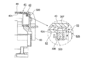
図18は本発明の第4の実施の形態におけるトナーカートリッジの要部を示す第1の断面図、図19は本発明の第4の実施の形態におけるトナーカートリッジの要部を示す第2の断面図、図20は本発明の第4の実施の形態におけるトナーカートリッジの要部を示す第3の断面図、図21は本発明の第4の実施の形態におけるテーパ角度を設定する方法を示す概念図である。 18 is a first cross-sectional view showing the main part of the toner cartridge according to the fourth embodiment of the present invention, and FIG. 19 is a second cross-section showing the main part of the toner cartridge according to the fourth embodiment of the present invention. FIG. 20, FIG. 20 is a third sectional view showing the main part of the toner cartridge in the fourth embodiment of the present invention, and FIG. 21 is a concept showing a method for setting the taper angle in the fourth embodiment of the present invention. FIG.
図に示されるように、現像剤供給口としてのトナー供給口44を開閉するための開閉部材としてのシャッタ62は摺動部62bを備え、該摺動部62bには、第1の凹溝としての内側凹溝306が形成される。該内側凹溝306は、断面が円形の形状を有し、シャッタ62における径方向内方ほど内径が大きくされ、径方向外方ほど内径が小さくされ、テーパ状の形状を有する内周面を有する。また、内側凹溝306は、操作部としての操作レバー63を回動させて、遮蔽部62cがトナー供給口44を覆う位置、すなわち、シャッタ62を閉鎖する位置に置かれたときに、最下部に向くように形成される。
As shown in the drawing, a
一方、前記操作レバー63には、摺動部62bを包囲し、該摺動部62bと摺動する部分の内周面に、所定の深さを有する係止部としての、かつ、第2の凹溝としての外側凹溝307が形成される。該外側凹溝307は、操作レバー63を回動させて、シャッタ62を閉鎖する位置に置いたときに、内側凹溝306と同じ位置になるように形成される。
On the other hand, the operating
前記外側凹溝307は、断面が円形の形状を有し、操作レバー63における径方向内方ほど内径が大きくされ、径方向外方ほど内径が小さくされ、内側凹溝306の内周面の延長線上に、テーパ状の形状を有する内周面を有する。前記内側凹溝306の内周面及び外側凹溝307の内周面は同じテーパ角度で形成される。
The outer
また、前記内側凹溝306内には、回動規制部材としての連結部材320が、摺動自在に収容され、かつ、自重により選択的に移動して外側凹溝307に進入し、操作レバー63とシャッタ62とを選択的に連結する。なお、連結部材320の長さをLとし、内側凹溝306の深さをdiとし、外側凹溝307の深さをdoとしたとき、
do<L<di
にされる。
A connecting
do <L <di
To be.
そして、前記連結部材320は、内側凹溝306及び外側凹溝307内において円滑に移動することができるように、断面が円形の形状を有し、連結部材320の外周面と前記内側凹溝306及び外側凹溝307の内周面とが同じテーパ角度で形成される。
The
次に、前記連結部材320の動作について説明する。
Next, the operation of the connecting
まず、図18に示されるように、トナーカートリッジ41を、トナー供給口44が上方に向くように置くと、連結部材320は、自重によって下方に下がり、解除位置を採る。このとき、連結部材320の長さLは、内側凹溝306の深さdiより短いので、内側凹溝306内に納まり、外側凹溝307と係合しなくなる。これにより、シャッタ62と操作レバー63との連結が解除されるので、操作レバー63を回動させてもシャッタ62の回動が阻止される。
First, as shown in FIG. 18, when the
次に、図19に示されるように、トナーカートリッジ41を、トナー供給口44が下方に向くように置くと、連結部材320は、自重によって下方に下がる。このとき、連結部材320は、外側凹溝307内に進入し、底面に接触するが、連結部材320の長さLは外側凹溝307の深さdoより長いので、外側凹溝307と係合させられる。これにより、シャッタ62と操作レバー63とが連結されるので、シャッタ42の回動が許容される。なお、前記連結部材320が底面に接触したときに、前記内側凹溝306及び外側凹溝307の内周面と連結部材320の外周面とが接触するように連結部材320の寸法が設定される。
Next, as shown in FIG. 19, when the
ところで、本実施の形態においては、トナーカートリッジ41を、図18に示されるように、トナー供給口44が上方に向くように置いた状態から傾けて、図18における反時計回りに90〔°〕回転させた場合、連結部材320は、図20に示されるように、内側凹溝306の底面に接触した状態に維持される。同様に、トナーカートリッジ41を傾けて、図18における時計回りに90〔°〕回転させた場合、連結部材320は、内側凹溝306の底面に接触した状態に維持される。
By the way, in the present embodiment, as shown in FIG. 18, the
すなわち、トナーカートリッジ41を、現像剤供給口44が上方に向く角度から側方に向く角度までの間の所定の角度に置いたとき、連結部材320は、内側凹溝306の底面に接触した状態に維持される。
That is, when the
これに対して、トナーカートリッジ41を、図19に示されるように、トナー供給口44が下方に向くように置いた状態から、図19における反時計回り、又は時計回りに90〔°〕回転させた場合に、連結部材320が、図19に示されるように外側凹溝307の底面に接触した状態に維持されると、シャッタ62と操作レバー63とが連結されたままになり、シャッタ42の回動が許容されたままになる。
On the other hand, as shown in FIG. 19, the
そこで、本実施の形態においては、前記トナーカートリッジ41を、図19に示されるように、トナー供給口44が下方に向くように置いた状態から傾けて、図19における反時計回り、又は時計回りに90〔°〕回転させた場合に、自重で移動して、図20に示されるように、内側凹溝306の底面に接触した状態になるように、前記内側凹溝306、外側凹溝307及び連結部材320の各テーパ角度を設定するようにしている。
Therefore, in the present embodiment, as shown in FIG. 19, the
すなわち、本実施の形態においては、前記テーパ角度をθとしたとき、トナーカートリッジ41を、トナー供給口44が下方に向くように置いた状態から傾けて、図19における反時計回り、又は時計回りに90〔°〕回転させた場合に、少なくとも回転が終了する時点で、連結部材320が、確実に前記外側凹溝307及び内側凹溝306の内周面を滑って移動し、内側凹溝306の底面に接触した状態になるように、
45〔°〕≧θ≧20〔°〕
に設定される。
That is, in the present embodiment, when the taper angle is θ, the
45 [°] ≧ θ ≧ 20 [°]
Set to
なお、前記テーパ角度θが45〔°〕より大きくなると、前記内側凹溝306の底面の寸法(面積)がその分大きくなり、内側凹溝306及び外側凹溝307の占有面積が大きくなるので、内側凹溝306及び外側凹溝307を形成する箇所に制約が生じてしまう。
When the taper angle θ is larger than 45 °, the size (area) of the bottom surface of the inner
一方、前記テーパ角度θが20〔°〕より小さくなると、前記内側凹溝306及び外側凹溝307内において連結部材320を確実に移動させることが困難になってしまう。
On the other hand, when the taper angle θ is smaller than 20 °, it is difficult to reliably move the connecting
すなわち、例えば、シャッタ62及び操作レバー63の材料が同じABS樹脂であり、連結部材320の材料がステンレス鋼(SUS)であり、ABS樹脂とステンレス鋼との静上摩擦係数μを0.37とし、連結部材320の重量Mgを0.3〔g〕としたとき、図21において、連結部材320を移動させるために、
Mg・sinθ≧μ・Mg・cosθ
θ≧tan-1μ≒20〔°〕
にする必要がある。
That is, for example, the
Mg · sinθ ≧ μ · Mg · cosθ
θ ≧ tan −1 μ ≒ 20 [°]
It is necessary to.
したがって、前述されたように、テーパ角度θを、
θ≧20〔°〕
にするのが好ましい。
Therefore, as described above, the taper angle θ is
θ ≧ 20 [°]
Is preferable.
このように、本実施の形態においては、操作レバー63に外側凹溝307が、摺動部62bに内側凹溝306が形成され、連結部材320が、外側凹溝307及び内側凹溝306内を移動して、操作レバー63とシャッタ62とを選択的に連結するので、不用意にトナー供給口44が開くことがなくなる。したがって、トナーカートリッジ41内に異物が混入するのを防止することができる。
As described above, in the present embodiment, the
前記各実施の形態においては、画像形成装置としてのプリンタについて説明しているが、本発明を、複写機、ファクシミリ装置、複合機等に適用することができる。 In each of the above embodiments, a printer as an image forming apparatus has been described. However, the present invention can be applied to a copying machine, a facsimile machine, a multifunction machine, and the like.
なお、本発明は前記各実施の形態に限定されるものではなく、本発明の趣旨に基づいて種々変形させることが可能であり、それらを本発明の範囲から排除するものではない。 The present invention is not limited to the above embodiments, and various modifications can be made based on the gist of the present invention, and they are not excluded from the scope of the present invention.
41 トナーカートリッジ
42、62 シャッタ
42d、63 操作レバー
43 ケース
44 トナー供給口
53、73、220、320 連結部材
41
Claims (9)
(b)該現像剤収容体に対して移動自在に配設され、移動に伴って、前記現像剤供給口を開閉する開閉部材と、
(c)該開閉部材を移動させるための操作部と、
(d)前記現像剤供給口の向きに応じて前記開閉部材の回動を阻止又は許容する回動規制部材とを有するとともに、
(e)該回動規制部材は、前記現像剤収容体及び操作部のうちの一方に形成された係止部と係脱させられる係合部を備え、現像剤収容体の前記現像剤供給口を上方に向けたときに、前記係止部と前記係合部とが係合させられて前記開閉部材の回動を阻止し、現像剤収容体の前記現像剤供給口を下方に向けたときに、前記係止部と前記係合部との係合が解除されて前記開閉部材の回動を許容することを特徴とする現像剤収容器。 (A) a developer container having a developer supply port formed thereon;
(B) an opening / closing member that is movably disposed with respect to the developer container, and that opens and closes the developer supply port in accordance with the movement;
(C) an operation unit for moving the opening and closing member;
(D) a rotation restricting member that prevents or allows the opening / closing member to rotate according to the direction of the developer supply port ;
(E) The rotation restricting member includes an engaging portion that is engaged with and disengaged from a locking portion formed on one of the developer accommodating body and the operation portion, and the developer supply port of the developer accommodating body When the engaging portion is engaged with the engaging portion to prevent the opening / closing member from rotating and the developer supply port of the developer container is directed downward In addition, the engagement between the engaging portion and the engaging portion is released to allow the opening / closing member to rotate .
(b)前記回動規制部材は、前記第1、第2の凹溝内を自重で移動する請求項1又は3に記載の現像剤収容器。 (A) The opening / closing member and the operation portion include first and second concave grooves that are selectively communicated,
(B) The developer container according to claim 1 or 3 , wherein the rotation restricting member moves under its own weight in the first and second concave grooves.
(b)前記回動規制部材は、前記第1、第2の凹溝内を自重で移動する請求項1又は6に記載の現像剤収容器。 (A) The opening / closing member and the operation portion are provided with first and second concave grooves that are selectively communicated and have an inner peripheral surface having a tapered shape,
(B) The developer container according to claim 1 or 6 , wherein the rotation restricting member moves by its own weight in the first and second concave grooves.
Priority Applications (4)
| Application Number | Priority Date | Filing Date | Title |
|---|---|---|---|
| JP2006292575A JP4388057B2 (en) | 2006-08-31 | 2006-10-27 | Developer container, image forming unit, and image forming apparatus |
| US11/892,733 US7747199B2 (en) | 2006-08-31 | 2007-08-27 | Developer material container, image forming unit, and image forming apparatus |
| EP07115080.9A EP1895368B1 (en) | 2006-08-31 | 2007-08-28 | Developer material container, image forming unit, and image forming apparatus |
| CN200710142249.6A CN101135880B (en) | 2006-08-31 | 2007-08-31 | Developer material container, image forming unit, and image forming apparatus |
Applications Claiming Priority (2)
| Application Number | Priority Date | Filing Date | Title |
|---|---|---|---|
| JP2006235647 | 2006-08-31 | ||
| JP2006292575A JP4388057B2 (en) | 2006-08-31 | 2006-10-27 | Developer container, image forming unit, and image forming apparatus |
Publications (2)
| Publication Number | Publication Date |
|---|---|
| JP2008083659A JP2008083659A (en) | 2008-04-10 |
| JP4388057B2 true JP4388057B2 (en) | 2009-12-24 |
Family
ID=38691346
Family Applications (1)
| Application Number | Title | Priority Date | Filing Date |
|---|---|---|---|
| JP2006292575A Active JP4388057B2 (en) | 2006-08-31 | 2006-10-27 | Developer container, image forming unit, and image forming apparatus |
Country Status (4)
| Country | Link |
|---|---|
| US (1) | US7747199B2 (en) |
| EP (1) | EP1895368B1 (en) |
| JP (1) | JP4388057B2 (en) |
| CN (1) | CN101135880B (en) |
Families Citing this family (13)
| Publication number | Priority date | Publication date | Assignee | Title |
|---|---|---|---|---|
| JP4612073B2 (en) * | 2008-03-19 | 2011-01-12 | 株式会社沖データ | Powder container, developing device, and image forming apparatus |
| JP5464478B2 (en) * | 2009-09-11 | 2014-04-09 | 株式会社リコー | Image forming apparatus |
| JP5011403B2 (en) * | 2010-01-29 | 2012-08-29 | 京セラドキュメントソリューションズ株式会社 | Shutter opening / closing mechanism and image forming apparatus having the same |
| JP5427843B2 (en) * | 2011-06-30 | 2014-02-26 | 京セラドキュメントソリューションズ株式会社 | Fixing apparatus and image forming apparatus |
| US8737887B2 (en) * | 2012-04-27 | 2014-05-27 | Lexmark International, Inc. | Shutter assembly for a toner container |
| CN202631957U (en) * | 2012-05-18 | 2012-12-26 | 珠海天威飞马打印耗材有限公司 | Toner cartridge |
| JP5896358B2 (en) * | 2013-01-21 | 2016-03-30 | 株式会社沖データ | Developer container, developing device, and image forming apparatus |
| JP6070392B2 (en) * | 2013-04-30 | 2017-02-01 | 株式会社リコー | Toner storage container support structure and image forming apparatus |
| JP5873048B2 (en) | 2013-07-12 | 2016-03-01 | 京セラドキュメントソリューションズ株式会社 | Toner container and image forming apparatus having the same |
| JP5683679B2 (en) * | 2013-11-28 | 2015-03-11 | 京セラドキュメントソリューションズ株式会社 | Image forming apparatus |
| JP6855716B2 (en) * | 2016-09-14 | 2021-04-07 | 富士ゼロックス株式会社 | Powder container, developer, and image forming equipment |
| JP7047674B2 (en) * | 2018-08-30 | 2022-04-05 | 沖電気工業株式会社 | Developer container, image forming unit and image forming apparatus |
| KR20200025348A (en) * | 2018-08-30 | 2020-03-10 | 휴렛-팩커드 디벨롭먼트 컴퍼니, 엘.피. | Toner refill cartridge with holder holding memory unit thereon and rotatable with respect to cartridge body |
Family Cites Families (5)
| Publication number | Priority date | Publication date | Assignee | Title |
|---|---|---|---|---|
| JPH0765564A (en) * | 1993-08-23 | 1995-03-10 | Matsushita Electric Ind Co Ltd | Portable player |
| JP3893259B2 (en) | 2001-08-07 | 2007-03-14 | 株式会社沖データ | Toner cartridge and image forming apparatus |
| JP2005227614A (en) * | 2004-02-13 | 2005-08-25 | Oki Data Corp | Toner cartridge and image forming apparatus loading the toner cartridge |
| JP2006235592A (en) * | 2005-01-31 | 2006-09-07 | Kyocera Mita Corp | Toner cartridge |
| JP4134061B2 (en) * | 2005-02-14 | 2008-08-13 | シャープ株式会社 | Toner cartridge and image forming apparatus to which the toner cartridge is mounted |
-
2006
- 2006-10-27 JP JP2006292575A patent/JP4388057B2/en active Active
-
2007
- 2007-08-27 US US11/892,733 patent/US7747199B2/en active Active
- 2007-08-28 EP EP07115080.9A patent/EP1895368B1/en active Active
- 2007-08-31 CN CN200710142249.6A patent/CN101135880B/en active Active
Also Published As
| Publication number | Publication date |
|---|---|
| US7747199B2 (en) | 2010-06-29 |
| EP1895368A3 (en) | 2010-08-11 |
| EP1895368A2 (en) | 2008-03-05 |
| CN101135880A (en) | 2008-03-05 |
| CN101135880B (en) | 2011-08-03 |
| JP2008083659A (en) | 2008-04-10 |
| EP1895368B1 (en) | 2016-11-16 |
| US20080056759A1 (en) | 2008-03-06 |
Similar Documents
| Publication | Publication Date | Title |
|---|---|---|
| JP4388057B2 (en) | Developer container, image forming unit, and image forming apparatus | |
| JP4702031B2 (en) | Image forming apparatus | |
| JP4612073B2 (en) | Powder container, developing device, and image forming apparatus | |
| JP5514697B2 (en) | Developing device, image forming unit, and image forming apparatus | |
| JP4543077B2 (en) | Toner cartridge and image forming apparatus | |
| JP5143674B2 (en) | Toner receiving apparatus and image forming apparatus | |
| JP2005316192A (en) | Electrophotographic image forming apparatus | |
| JP5962982B2 (en) | Image forming apparatus | |
| US20090016767A1 (en) | Developer storing container, developing unit, developing device and image forming apparatus | |
| JP4842683B2 (en) | Image forming apparatus | |
| JP2004264539A (en) | Toner cartridge and image forming apparatus | |
| US9772582B2 (en) | Developer container, cartridge, image formation unit and image formation apparatus | |
| JP2006308928A (en) | Developer supply cartridge, process cartridge, and electrophotographic image forming apparatus | |
| JP2006058913A (en) | Image forming apparatus | |
| JP3765213B2 (en) | Toner supply device | |
| JP2008216580A (en) | Image forming unit and image forming apparatus | |
| JP2008080613A (en) | Image forming apparatus and its cleaning method | |
| JP5532828B2 (en) | Process cartridge and image forming apparatus | |
| JP2006235529A (en) | Image forming apparatus | |
| JP2016206544A (en) | Toner cartridge, image forming unit and image forming apparatus | |
| JP2005227614A (en) | Toner cartridge and image forming apparatus loading the toner cartridge | |
| JP4243620B2 (en) | Image forming apparatus | |
| JP2004046197A (en) | Color image forming device | |
| JP2007025346A (en) | Process cartridge | |
| JP2009271287A (en) | Image forming apparatus |
Legal Events
| Date | Code | Title | Description |
|---|---|---|---|
| A621 | Written request for application examination |
Free format text: JAPANESE INTERMEDIATE CODE: A621 Effective date: 20080717 |
|
| A977 | Report on retrieval |
Free format text: JAPANESE INTERMEDIATE CODE: A971007 Effective date: 20081112 |
|
| A131 | Notification of reasons for refusal |
Free format text: JAPANESE INTERMEDIATE CODE: A131 Effective date: 20090127 |
|
| A521 | Request for written amendment filed |
Free format text: JAPANESE INTERMEDIATE CODE: A523 Effective date: 20090325 |
|
| TRDD | Decision of grant or rejection written | ||
| A01 | Written decision to grant a patent or to grant a registration (utility model) |
Free format text: JAPANESE INTERMEDIATE CODE: A01 Effective date: 20090929 |
|
| A01 | Written decision to grant a patent or to grant a registration (utility model) |
Free format text: JAPANESE INTERMEDIATE CODE: A01 |
|
| A61 | First payment of annual fees (during grant procedure) |
Free format text: JAPANESE INTERMEDIATE CODE: A61 Effective date: 20091001 |
|
| R150 | Certificate of patent or registration of utility model |
Ref document number: 4388057 Country of ref document: JP Free format text: JAPANESE INTERMEDIATE CODE: R150 Free format text: JAPANESE INTERMEDIATE CODE: R150 |
|
| FPAY | Renewal fee payment (event date is renewal date of database) |
Free format text: PAYMENT UNTIL: 20121009 Year of fee payment: 3 |
|
| FPAY | Renewal fee payment (event date is renewal date of database) |
Free format text: PAYMENT UNTIL: 20121009 Year of fee payment: 3 |
|
| FPAY | Renewal fee payment (event date is renewal date of database) |
Free format text: PAYMENT UNTIL: 20131009 Year of fee payment: 4 |
|
| S111 | Request for change of ownership or part of ownership |
Free format text: JAPANESE INTERMEDIATE CODE: R313111 |
|
| R350 | Written notification of registration of transfer |
Free format text: JAPANESE INTERMEDIATE CODE: R350 |