KR20200025348A - Toner refill cartridge with holder holding memory unit thereon and rotatable with respect to cartridge body - Google Patents

Toner refill cartridge with holder holding memory unit thereon and rotatable with respect to cartridge body Download PDF

Info

Publication number
KR20200025348A
KR20200025348A KR1020180102559A KR20180102559A KR20200025348A KR 20200025348 A KR20200025348 A KR 20200025348A KR 1020180102559 A KR1020180102559 A KR 1020180102559A KR 20180102559 A KR20180102559 A KR 20180102559A KR 20200025348 A KR20200025348 A KR 20200025348A
Authority
KR
South Korea
Prior art keywords
toner
holder
discharge
rotated
cartridge
Prior art date
Application number
KR1020180102559A
Other languages
Korean (ko)
Inventor
문지원
최웅용
Original Assignee
휴렛-팩커드 디벨롭먼트 컴퍼니, 엘.피.
Priority date (The priority date is an assumption and is not a legal conclusion. Google has not performed a legal analysis and makes no representation as to the accuracy of the date listed.)
Filing date
Publication date
Application filed by 휴렛-팩커드 디벨롭먼트 컴퍼니, 엘.피. filed Critical 휴렛-팩커드 디벨롭먼트 컴퍼니, 엘.피.
Priority to KR1020180102559A priority Critical patent/KR20200025348A/en
Priority to CN201880092954.6A priority patent/CN112041760B/en
Priority to US17/049,390 priority patent/US11209750B2/en
Priority to PCT/KR2018/016415 priority patent/WO2020045763A1/en
Publication of KR20200025348A publication Critical patent/KR20200025348A/en

Links

Images

Classifications

    • GPHYSICS
    • G03PHOTOGRAPHY; CINEMATOGRAPHY; ANALOGOUS TECHNIQUES USING WAVES OTHER THAN OPTICAL WAVES; ELECTROGRAPHY; HOLOGRAPHY
    • G03GELECTROGRAPHY; ELECTROPHOTOGRAPHY; MAGNETOGRAPHY
    • G03G15/00Apparatus for electrographic processes using a charge pattern
    • G03G15/06Apparatus for electrographic processes using a charge pattern for developing
    • G03G15/08Apparatus for electrographic processes using a charge pattern for developing using a solid developer, e.g. powder developer
    • G03G15/0822Arrangements for preparing, mixing, supplying or dispensing developer
    • G03G15/0877Arrangements for metering and dispensing developer from a developer cartridge into the development unit
    • G03G15/0881Sealing of developer cartridges
    • G03G15/0886Sealing of developer cartridges by mechanical means, e.g. shutter, plug
    • GPHYSICS
    • G03PHOTOGRAPHY; CINEMATOGRAPHY; ANALOGOUS TECHNIQUES USING WAVES OTHER THAN OPTICAL WAVES; ELECTROGRAPHY; HOLOGRAPHY
    • G03GELECTROGRAPHY; ELECTROPHOTOGRAPHY; MAGNETOGRAPHY
    • G03G15/00Apparatus for electrographic processes using a charge pattern
    • G03G15/06Apparatus for electrographic processes using a charge pattern for developing
    • G03G15/08Apparatus for electrographic processes using a charge pattern for developing using a solid developer, e.g. powder developer
    • G03G15/0822Arrangements for preparing, mixing, supplying or dispensing developer
    • G03G15/0863Arrangements for preparing, mixing, supplying or dispensing developer provided with identifying means or means for storing process- or use parameters, e.g. an electronic memory
    • GPHYSICS
    • G03PHOTOGRAPHY; CINEMATOGRAPHY; ANALOGOUS TECHNIQUES USING WAVES OTHER THAN OPTICAL WAVES; ELECTROGRAPHY; HOLOGRAPHY
    • G03GELECTROGRAPHY; ELECTROPHOTOGRAPHY; MAGNETOGRAPHY
    • G03G21/00Arrangements not provided for by groups G03G13/00 - G03G19/00, e.g. cleaning, elimination of residual charge
    • G03G21/16Mechanical means for facilitating the maintenance of the apparatus, e.g. modular arrangements
    • G03G21/18Mechanical means for facilitating the maintenance of the apparatus, e.g. modular arrangements using a processing cartridge, whereby the process cartridge comprises at least two image processing means in a single unit
    • G03G21/1803Arrangements or disposition of the complete process cartridge or parts thereof
    • G03G21/181Manufacturing or assembling, recycling, reuse, transportation, packaging or storage
    • GPHYSICS
    • G03PHOTOGRAPHY; CINEMATOGRAPHY; ANALOGOUS TECHNIQUES USING WAVES OTHER THAN OPTICAL WAVES; ELECTROGRAPHY; HOLOGRAPHY
    • G03GELECTROGRAPHY; ELECTROPHOTOGRAPHY; MAGNETOGRAPHY
    • G03G15/00Apparatus for electrographic processes using a charge pattern
    • G03G15/06Apparatus for electrographic processes using a charge pattern for developing
    • G03G15/08Apparatus for electrographic processes using a charge pattern for developing using a solid developer, e.g. powder developer
    • G03G15/0822Arrangements for preparing, mixing, supplying or dispensing developer
    • G03G15/0865Arrangements for supplying new developer
    • GPHYSICS
    • G03PHOTOGRAPHY; CINEMATOGRAPHY; ANALOGOUS TECHNIQUES USING WAVES OTHER THAN OPTICAL WAVES; ELECTROGRAPHY; HOLOGRAPHY
    • G03GELECTROGRAPHY; ELECTROPHOTOGRAPHY; MAGNETOGRAPHY
    • G03G15/00Apparatus for electrographic processes using a charge pattern
    • G03G15/06Apparatus for electrographic processes using a charge pattern for developing
    • G03G15/08Apparatus for electrographic processes using a charge pattern for developing using a solid developer, e.g. powder developer
    • G03G15/0894Reconditioning of the developer unit, i.e. reusing or recycling parts of the unit, e.g. resealing of the unit before refilling with toner
    • GPHYSICS
    • G03PHOTOGRAPHY; CINEMATOGRAPHY; ANALOGOUS TECHNIQUES USING WAVES OTHER THAN OPTICAL WAVES; ELECTROGRAPHY; HOLOGRAPHY
    • G03GELECTROGRAPHY; ELECTROPHOTOGRAPHY; MAGNETOGRAPHY
    • G03G21/00Arrangements not provided for by groups G03G13/00 - G03G19/00, e.g. cleaning, elimination of residual charge
    • G03G21/16Mechanical means for facilitating the maintenance of the apparatus, e.g. modular arrangements
    • G03G21/18Mechanical means for facilitating the maintenance of the apparatus, e.g. modular arrangements using a processing cartridge, whereby the process cartridge comprises at least two image processing means in a single unit
    • G03G21/1875Mechanical means for facilitating the maintenance of the apparatus, e.g. modular arrangements using a processing cartridge, whereby the process cartridge comprises at least two image processing means in a single unit provided with identifying means or means for storing process- or use parameters, e.g. lifetime of the cartridge
    • G03G21/1878Electronically readable memory
    • GPHYSICS
    • G03PHOTOGRAPHY; CINEMATOGRAPHY; ANALOGOUS TECHNIQUES USING WAVES OTHER THAN OPTICAL WAVES; ELECTROGRAPHY; HOLOGRAPHY
    • G03GELECTROGRAPHY; ELECTROPHOTOGRAPHY; MAGNETOGRAPHY
    • G03G2215/00Apparatus for electrophotographic processes
    • G03G2215/06Developing structures, details
    • G03G2215/066Toner cartridge or other attachable and detachable container for supplying developer material to replace the used material
    • G03G2215/0663Toner cartridge or other attachable and detachable container for supplying developer material to replace the used material having a longitudinal rotational axis, around which at least one part is rotated when mounting or using the cartridge
    • G03G2215/0665Generally horizontally mounting of said toner cartridge parallel to its longitudinal rotational axis
    • G03G2215/0668Toner discharging opening at one axial end
    • GPHYSICS
    • G03PHOTOGRAPHY; CINEMATOGRAPHY; ANALOGOUS TECHNIQUES USING WAVES OTHER THAN OPTICAL WAVES; ELECTROGRAPHY; HOLOGRAPHY
    • G03GELECTROGRAPHY; ELECTROPHOTOGRAPHY; MAGNETOGRAPHY
    • G03G2215/00Apparatus for electrophotographic processes
    • G03G2215/06Developing structures, details
    • G03G2215/066Toner cartridge or other attachable and detachable container for supplying developer material to replace the used material
    • G03G2215/0663Toner cartridge or other attachable and detachable container for supplying developer material to replace the used material having a longitudinal rotational axis, around which at least one part is rotated when mounting or using the cartridge
    • G03G2215/0673Generally vertically mounting of said toner cartridge parallel to its longitudinal rotational axis

Abstract

According to the present invention, a toner cartridge comprises: a body housing a toner and having a toner discharge unit; a plunger provided at the body to push the toner out of the body through the toner discharge unit; a memory unit including an electric contact unit having at least one electric contact; and a holder having the memory unit mounted thereon and rotatable relative to a home position and a rotated position with respect to the body.

Description

메모리 유닛을 수납하고 몸체에 대하여 상대 회전 가능한 홀더를 구비하는 토너 리필 카트리지{Toner refill cartridge with holder holding memory unit thereon and rotatable with respect to cartridge body}Toner refill cartridge with holder holding memory unit thereon and rotatable with respect to cartridge body}

전자사진방식을 이용하는 프린터는, 감광체에 형성된 정전잠상에 토너를 공급하여 감광체 상에 가시적인 토너 화상을 형성하고, 이 토너 화상을 중간 전사 매체를 거쳐 또는 직접 인쇄 매체로 전사한 후, 전사된 토너 화상을 인쇄 매체에 정착시킨다. A printer using an electrophotographic method supplies a toner on an electrostatic latent image formed on the photosensitive member to form a visible toner image on the photosensitive member, transfers the toner image through an intermediate transfer medium or directly to a printing medium, and then transfers the toner. The image is fixed to the print medium.

현상 카트리지는 토너를 수용하며, 감광체에 형성된 정전잠상에 토너를 공급하여 가시적인 토너 화상을 형성한다. 현상 카트리지에 수용된 토너가 모두 소모되면, 현상 카트리지는 프린터 본체로부터 탈거되며, 새로운 현상 카트리지가 본체에 장착될 수 있다. 토너 카트리지(토너 리필 카트리지)를 이용하여 현상 카트리지에 새로운 토너를 충전할 수도 있다.The developing cartridge accommodates the toner and supplies the toner to the electrostatic latent image formed on the photosensitive member to form a visible toner image. When all of the toner contained in the development cartridge is exhausted, the development cartridge is removed from the printer main body, and a new development cartridge can be mounted in the main body. The toner cartridge (toner refill cartridge) may also be used to charge new toner to the developing cartridge.

도 1은 전자사진방식 프린터의 일 실시예의 개략적인 외관 사시도이다.
도 2는 도 1에 도시된 전자사진방식 프린터의 일 실시예의 개략적인 구성도이다.
도 3은 토너 카트리지가 토너 충전부에 장착된 상태를 보여주는 개략적인 사시도이다.
도 4는 토너 카트리지의 일 실시예의 사시도이다.
도 5는 토너 카트리지의 일 실시예의 분해 사시도이다.
도 6은 홀더가 홈 위치에 위치된 상태를 보여준다.
도 7은 홀더가 회전된 위치에 위치된 상태를 보여준다.
도 8은 토너 충전부의 일 실시예의 분해 사시도이다.
도 9는 토너 카트리지가 장착 위치에 위치된 상태에서 제1토너 배출부, 제2토너 배출부, 잠금 부재, 홀더의 위치관계를 보여준다.
도 10은 토너 카트리지가 장착 위치에 위치된 상태에서 제2토너 배출부, 제2토너 유입부, 제1토너 유입부의 위치관계를 보여준다.
도 11은 토너 카트리지가 제1각위치에 위치된 상태에서 제1토너 배출부, 제2토너 배출부, 잠금 부재, 홀더의 위치관계를 보여준다.
도 12는 토너 카트리지가 제1각위치에 위치된 상태에서 제2토너 배출부, 제2토너 유입부, 제1토너 유입부의 위치관계를 보여준다.
도 13은 토너 카트리지가 제2각위치에 위치된 상태에서 제1토너 배출부, 제2토너 배출부, 잠금 부재, 홀더의 위치관계를 보여준다.
도 14는 토너 카트리지가 제2각위치에 위치된 상태에서 제2토너 배출부, 제2토너 유입부, 제1토너 유입부의 위치관계를 보여준다.
1 is a schematic external perspective view of an embodiment of an electrophotographic printer.
FIG. 2 is a schematic structural diagram of an embodiment of the electrophotographic printer shown in FIG. 1.
3 is a schematic perspective view showing a state where a toner cartridge is mounted in a toner charging unit.
4 is a perspective view of one embodiment of a toner cartridge.
5 is an exploded perspective view of one embodiment of a toner cartridge.
6 shows the holder in the home position.
7 shows a state where the holder is located in the rotated position.
8 is an exploded perspective view of one embodiment of a toner filling unit;
Fig. 9 shows the positional relationship of the first toner discharge portion, the second toner discharge portion, the locking member, and the holder in the state where the toner cartridge is located at the mounting position.
Fig. 10 shows the positional relationship of the second toner discharge portion, the second toner inlet portion, and the first toner inlet portion with the toner cartridge in the mounting position.
Fig. 11 shows the positional relationship of the first toner discharge portion, the second toner discharge portion, the locking member, and the holder in the state where the toner cartridge is located at the first angular position.
12 shows the positional relationship of the second toner discharge portion, the second toner inlet portion, and the first toner inlet portion with the toner cartridge positioned at the first angular position.
Fig. 13 shows the positional relationship of the first toner discharge portion, the second toner discharge portion, the locking member, and the holder in the state where the toner cartridge is located at the second angular position.
14 shows the positional relationship of the second toner discharge portion, the second toner inlet portion, and the first toner inlet portion with the toner cartridge positioned at the second respective positions.

도 1은 전자사진방식 프린터의 일 실시예의 개략적인 외관 사시도이다. 도 2는 도 1에 도시된 전자사진방식 프린터의 일 실시예의 개략적인 구성도이다. 도 1과 도 2를 참조하면, 프린터는 본체(1)와, 본체(1)에 착탈 가능한 카트리지 형태의 현상 카트리지(2)를 구비할 수 있다. 본체(1)에는 도어(3)가 마련될 수 있다. 도어(3)는 본체(1)의 일부를 개폐한다. 도 1에는 본체(1)의 상부를 개방하는 도어(3)가 도시되어 있으나, 필요에 따라서 본체(1)의 측부 또는 전부를 개방하는 도어가 채용될 수도 있다. 도어(3)를 열고, 현상 카트리지(2)를 본체(1)에/로부터 장착/탈거할 수 있다. 1 is a schematic external perspective view of an embodiment of an electrophotographic printer. FIG. 2 is a schematic structural diagram of an embodiment of the electrophotographic printer shown in FIG. 1. 1 and 2, the printer may include a main body 1 and a developing cartridge 2 in a cartridge form detachable from the main body 1. The main body 1 may be provided with a door 3. The door 3 opens and closes a part of the main body 1. Although the door 3 which opens the upper part of the main body 1 is shown in FIG. 1, the door which opens the side part or all part of the main body 1 may be employ | adopted as needed. The door 3 is opened, and the developing cartridge 2 can be attached / detached to / from the main body 1.

감광드럼(21)은 정전잠상이 형성되는 감광체의 일 예로서, 원통형 금속 파이프와 그 외주에 형성되는 광도전성을 가지는 감광층을 포함할 수 있다. 대전롤러(23)는 감광드럼(21)의 그 표면을 균일한 전위로 대전시키는 대전기의 일 예이다. 대전롤러(23)에는 대전바이어스전압이 인가된다. 대전롤러(23) 대신에 코로나 대전기(미도시)가 사용될 수도 있다. 현상롤러(22)는 토너를 감광드럼(21)의 표면에 형성되는 정전잠상에 공급하여 현상시킨다. The photosensitive drum 21 may include a cylindrical metal pipe and a photosensitive layer having photoconductivity formed on an outer circumference thereof as an example of a photosensitive member in which an electrostatic latent image is formed. The charging roller 23 is an example of a charger for charging the surface of the photosensitive drum 21 to a uniform potential. The charging bias voltage is applied to the charging roller 23. Instead of the charging roller 23, a corona charger (not shown) may be used. The developing roller 22 supplies the toner to the electrostatic latent image formed on the surface of the photosensitive drum 21 for development.

현상제로서 토너와 캐리어를 사용하는 이성분 현상방식의 경우, 현상롤러(22)는 회전되는 슬리브 내부에 마그넷이 고정적으로 설치된 형태일 수 있다. 슬리브는 감광드럼(21)으로부터 수십 내지 수백 마이크로미터 이격되게 위치될 수 있다. 마그넷의 자기력에 의하여 캐리어가 현상롤러(22)의 외주에 부착되고, 토너는 정전력에 의하여 캐리어에 부착되어 현상롤러(22)의 외주에는 캐리어와 토너로 된 자기 브러쉬가 형성된다. 현상롤러(22)에 인가되는 현상바이어스에 의하여 토너만이 감광드럼(21)에 형성된 정전잠상으로 이동된다.In the case of the two-component developing method using a toner and a carrier as a developer, the developing roller 22 may be in a form in which a magnet is fixedly installed inside the sleeve to be rotated. The sleeve may be positioned tens to hundreds of micrometers apart from the photosensitive drum 21. The carrier is attached to the outer circumference of the developing roller 22 by the magnetic force of the magnet, and the toner is attached to the carrier by the electrostatic force, and a magnetic brush made of the carrier and the toner is formed on the outer circumference of the developing roller 22. Only the toner is moved to the electrostatic latent image formed on the photosensitive drum 21 by the developing bias applied to the developing roller 22.

현상제로서 토너를 사용하는 일성분 현상방식의 경우, 현상롤러(22)는 감광드럼(21)에 접촉될 수 있으며, 감광드럼(21)으로부터 수십 내지 수백 마이크로미터 이격되게 위치될 수도 있다. 본 실시예에서는 현상롤러(22)와 감광드럼(21)이 서로 접촉되어 현상닙을 형성하는 일성분 접촉현상방식이 채용된다. 현상롤러(22)는 도전성 금속 코어(미도시)의 외주에 탄성층(미도시)형성된 형태일 수 있다. 현상롤러(22)에 현상바이어스전압이 인가되면 현상닙을 통하여 토너가 감광드럼(21)의 표면에 형성된 정전잠상으로 이동되어 부착된다.In the case of a one-component developing method using toner as a developer, the developing roller 22 may be in contact with the photosensitive drum 21, and may be positioned several tens to hundreds of micrometers apart from the photosensitive drum 21. In this embodiment, a one-component contact developing method in which the developing roller 22 and the photosensitive drum 21 are in contact with each other to form a developing nip is employed. The developing roller 22 may have a form in which an elastic layer (not shown) is formed on an outer circumference of a conductive metal core (not shown). When a developing bias voltage is applied to the developing roller 22, the toner is moved and adhered to the electrostatic latent image formed on the surface of the photosensitive drum 21 through the developing nip.

공급롤러(24)는 토너를 현상롤러(22)에 부착시킨다. 공급롤러(24)에 토너를 현상롤러(22)로 부착시키기 위하여 공급바이어스전압이 인가될 수 있다. 참조부호 25는 현상롤러(22)의 표면에 부착되는 토너의 양을 규제하기 위한 규제부재를 표시한다. 규제부재(25)는 예를 들어 그 선단이 현상롤러(22)에 소정의 압력으로 접촉되는 규제 블레이드일 수 있다. 참조부호 26은 대전 전에 감광드럼(21)의 표면으로부터 잔류토너 및 이물질을 제거하기 위한 클리닝 부재를 표시한다. 클리닝 부재(26)는 예를 들어 그 선단이 감광드럼(21)의 표면에 접촉되는 클리닝 블레이드일 수 있다. 이하에서, 감광드럼(21)의 표면으로부터 제거된 이물질을 폐토너로 지칭한다. The supply roller 24 attaches the toner to the developing roller 22. A supply bias voltage can be applied to attach the toner to the supply roller 24 with the developing roller 22. Reference numeral 25 denotes a regulating member for regulating the amount of toner adhered to the surface of the developing roller 22. The regulating member 25 may be, for example, a regulating blade whose tip is in contact with the developing roller 22 at a predetermined pressure. Reference numeral 26 denotes a cleaning member for removing residual toner and foreign matter from the surface of the photosensitive drum 21 before charging. The cleaning member 26 may be, for example, a cleaning blade whose tip is in contact with the surface of the photosensitive drum 21. Hereinafter, the foreign matter removed from the surface of the photosensitive drum 21 is referred to as waste toner.

광주사기(4)는 화상정보에 따라 변조된 광을 균일한 전위로 대전된 감광드럼(21)의 표면에 주사한다. 광주사기(4)로서, 예를 들면 레이저 다이오드로부터 조사되는 광을 폴리곤미러를 이용하여 주주사방향으로 편향시켜 감광드럼(21)에 주사하는 LSU(laser scanning unit)가 채용될 수 있다. The optical scanner 4 scans the light modulated according to the image information onto the surface of the photosensitive drum 21 charged at a uniform electric potential. As the optical scanner 4, for example, a laser scanning unit (LSU) which scans the photosensitive drum 21 by deflecting light irradiated from the laser diode in the main scanning direction using a polygon mirror may be employed.

전사롤러(5)는 감광드럼(21)과 대향되게 위치되어 전사닙을 형성하는 전사기의 일 예이다. 전사롤러(5)에는 감광드럼(21)의 표면에 현상된 토너화상을 인쇄매체(P)로 전사시키기 위한 전사바이어스전압이 인가된다. 전사롤러(5)대신에 코로나 전사기가 사용될 수도 있다. The transfer roller 5 is an example of a transfer machine which is positioned to face the photosensitive drum 21 to form a transfer nip. A transfer bias voltage for transferring the toner image developed on the surface of the photosensitive drum 21 to the print medium P is applied to the transfer roller 5. A corona transfer machine may be used instead of the transfer roller 5.

전사롤러(5)에 의하여 인쇄매체(P)의 표면으로 전사된 토너화상은 정전기적 인력에 의하여 인쇄매체(P)의 표면에 유지된다. 정착기(6)는 토너화상이 열과 압력을 가하여 인쇄매체(P)에 정착시킴으로써 인쇄매체(P)에 영구적인 인쇄화상을 형성한다.The toner image transferred to the surface of the print medium P by the transfer roller 5 is held on the surface of the print medium P by electrostatic attraction. The fixing unit 6 forms a permanent print image on the print medium P by fixing the toner image onto the print medium P by applying heat and pressure.

도 3은 토너 카트리지(9)가 토너 충전부(10)에 장착된 상태를 보여주는 개략적인 사시도이다. 도 2와 도 3을 참조하면, 본 실시예의 현상 카트리지(2)는 감광드럼(21)과 현상롤러(22)가 설치된 현상부(210)와, 감광드럼(21)으로부터 제거된 폐토너가 수용되는 폐토너 수용부(220)와, 현상부(210)와 연결되고 토너가 수용되는 토너 수용부(230)를 구비한다. 토너 수용부(230)에 토너를 충전하기 위하여, 현상 카트리지(2)는 토너 수용부(230)와 연결된 토너 충전부(10)를 구비한다. 토너 충전부(10)는 후술하는 토너 카트리지(9)와 현상 카트리지(2)와의 인터페이스를 제공한다. 현상 카트리지(2)는 현상부(210)와, 폐토너 수용부(220)와, 토너 수용부(230)와, 토너 충전부(10)를 구비하는 일체형 현상 카트리지이다. 3 is a schematic perspective view showing a state where the toner cartridge 9 is mounted in the toner charging unit 10. 2 and 3, the developing cartridge 2 according to the present embodiment accommodates the developing unit 210 in which the photosensitive drum 21 and the developing roller 22 are installed, and the waste toner removed from the photosensitive drum 21. A waste toner container 220 and a toner container 230 connected to the developing unit 210 to accommodate toner. In order to fill the toner in the toner container 230, the developing cartridge 2 includes a toner charger 10 connected to the toner container 230. The toner charging section 10 provides an interface between the toner cartridge 9 and the developing cartridge 2 described later. The developing cartridge 2 is an integrated developing cartridge including a developing unit 210, a waste toner container 220, a toner container 230, and a toner filling unit 10.

감광드럼(21)의 외주의 일부분은 하우징의 외부로 노출된다. 감광드럼(21)의 노출된 부분에 전사롤러(5)가 접촉되어 전사닙을 형성한다. 현상부(210)에는 토너를 현상롤러(22) 쪽으로 운반하는 하나 이상의 운반 부재가 설치될 수 있다. 운반부재는 토너를 휘저어 토너를 소정 전위로 대전시키는 역할을 겸할 수 있다. A portion of the outer circumference of the photosensitive drum 21 is exposed to the outside of the housing. The transfer roller 5 is in contact with the exposed portion of the photosensitive drum 21 to form a transfer nip. The developing unit 210 may be provided with one or more conveying members for conveying the toner toward the developing roller 22. The conveying member may serve to whip the toner to charge the toner to a predetermined potential.

폐토너 수용부(220)는 현상부(210)의 상측에 위치된다. 폐토너 수용부(220)는 현상부(210)로부터 상방으로 이격되어 그 사이에 광 통로(250)를 형성시킨다. 클리닝 부재(26)에 의하여 감광드럼(21)으로부터 제거된 폐토너는 폐토너 수용부(220)에 수용된다. 감광드럼(21)의 표면으로부터 제거된 폐토너는 하나 이상의 폐토너 이송부재(221)(222)(223)에 의하여 폐토너 수용부(220)의 내부로 이송된다. 폐토너 이송부재의 형태와 갯수는 특별히 제한되지 않는다. 폐토너 수용부(220)의 용적이나 형태를 감안하여 효과적으로 폐토너를 폐토너 수용부(220) 내부에 분산시킬 수 있는 적절한 위치에 적절한 수의 폐토너 이송부재가 설치될 수 있다.The waste toner container 220 is located above the developing unit 210. The waste toner container 220 is spaced upward from the developing part 210 to form a light passage 250 therebetween. The waste toner removed from the photosensitive drum 21 by the cleaning member 26 is accommodated in the waste toner container 220. Waste toner removed from the surface of the photosensitive drum 21 is transferred into the waste toner container 220 by one or more waste toner transfer members 221, 222, and 223. The shape and number of waste toner conveying members are not particularly limited. In consideration of the volume or shape of the waste toner container 220, an appropriate number of waste toner conveying members may be installed at an appropriate position to effectively disperse the waste toner inside the waste toner container 220.

토너 수용부(230)는 토너 충전부(10)와 연결되어 토너를 수용한다. 토너 수용부(230)는 도 2에 점선으로 도시된 바와 같이 토너 공급부(234)에 의하여 현상부(210)와 연결된다. 도 2에 도시된 바와 같이, 토너 공급부(234)는 폐토너 수용부(220)를 상하 방향으로 관통하여 현상부(210)에 연결될 수 있다. 토너 공급부(234)는 광주사기(4)에 의하여 주주사 방향으로 주사되는 노광 광(L)과 간섭되지 않도록 노광 광(L)의 유효 폭의 외측에 위치된다. The toner receiver 230 is connected to the toner charging unit 10 to receive the toner. The toner accommodating part 230 is connected to the developing part 210 by the toner supply part 234 as shown by a dotted line in FIG. 2. As shown in FIG. 2, the toner supply unit 234 may be connected to the developing unit 210 by penetrating the waste toner container 220 in the vertical direction. The toner supply unit 234 is located outside the effective width of the exposure light L so as not to interfere with the exposure light L scanned in the main scanning direction by the optical scanner 4.

토너 수용부(230)에는 토너를 토너 공급부(234)를 통하여 현상부(210)로 공급하기 위한 하나 이상의 토너 공급부재(231)(232)(233)가 설치될 수 있다. 토너 공급 부재의 형태와 갯수는 특별히 제한되지 않는다. 토너 수용부(230)의 용적이나 형태를 감안하여 효과적으로 토너를 현상부(210)로 공급하기 위하여 토너 수용부(230)에는 적절한 위치에 적절한 수의 토너 공급부재가 설치될 수 있다. 토너 공급부재(233)는 토너를 주주사 방향으로 운반하여, 토너 공급부(234)로 전달할 수 있다. The toner receiving unit 230 may be provided with one or more toner supply members 231, 232, and 233 for supplying toner to the developing unit 210 through the toner supply unit 234. The shape and number of toner supply members are not particularly limited. In consideration of the volume or shape of the toner accommodating portion 230, an appropriate number of toner supply members may be installed in the toner accommodating portion 230 at an appropriate position in order to supply the toner to the developing portion 210 effectively. The toner supply member 233 may transport the toner in the main scanning direction and transfer the toner to the toner supply unit 234.

상술한 구성에 의한 화상형성과정을 간략히 설명한다. 대전롤러(23)에 대전바이어스가 인가되고, 감광드럼(21)은 균일한 전위로 대전된다. 광주사기(4)는 화상정보에 대응되어 변조된 광을 감광드럼(21)으로 주사하여, 감광드럼(21)의 표면에 정전잠상을 형성시킨다. 공급롤러(24)는 토너를 현상롤러(22)의 표면에 부착시킨다. 규제부재(25)는 현상롤러(22)의 표면에 균일한 두께의 토너층을 형성시킨다. 현상롤러(22)에는 현상바이어스전압이 인가된다. 현상롤러(22)가 회전됨에 따라 현상닙으로 운반된 토너는 현상바이어스전압에 의하여 감광드럼(21)의 표면에 형성된 정전잠상으로 이동되어 부착되어 감광드럼(21)의 표면에는 가시적인 토너화상이 형성된다. 픽업롤러(71)에 의하여 적재수단(7)으로부터 인출된 인쇄매체(P)는 이송롤러(72)에 의하여 전사롤러(5)와 감광드럼(21)이 대면된 전사닙으로 이송된다. 전사롤러(5)에 전사바이어스전압이 인가되면, 정전기적 인력에 의하여 토너화상은 인쇄매체(P)로 전사된다. 인쇄매체(P)로 전사된 토너화상이 정착기(6)로부터 열과 압력을 받아 인쇄매체(P)에 정착됨으로써 인쇄가 완료된다. 인쇄매체(P)는 배출롤러(73)에 의하여 배출된다. 인쇄매체(P)로 전사되지 않고 감광드럼(21)의 표면에 잔류되는 토너는 클리닝 부재(26)에 의하여 제거된다.The image forming process by the above configuration will be briefly described. A charging bias is applied to the charging roller 23, and the photosensitive drum 21 is charged at a uniform electric potential. The optical scanning machine 4 scans the light modulated in correspondence with the image information to the photosensitive drum 21 to form an electrostatic latent image on the surface of the photosensitive drum 21. The feed roller 24 adheres toner to the surface of the developing roller 22. The restricting member 25 forms a toner layer of uniform thickness on the surface of the developing roller 22. The developing bias voltage is applied to the developing roller 22. As the developing roller 22 is rotated, the toner conveyed to the developing nip is moved to and adhered to the electrostatic latent image formed on the surface of the photosensitive drum 21 by the developing bias voltage so that a visible toner image is visible on the surface of the photosensitive drum 21. Is formed. The print medium P taken out from the stacking means 7 by the pickup roller 71 is transferred to the transfer nip facing the transfer roller 5 and the photosensitive drum 21 by the transfer roller 72. When a transfer bias voltage is applied to the transfer roller 5, the toner image is transferred to the print medium P by electrostatic attraction. The toner image transferred to the printing medium P is fixed to the printing medium P by receiving heat and pressure from the fixing unit 6 to complete printing. The print medium P is discharged by the discharge roller 73. The toner remaining on the surface of the photosensitive drum 21 without being transferred to the print medium P is removed by the cleaning member 26.

전술한 바와 같이, 본 실시예의 현상 카트리지(2)는 토너를 충전할 수 있는 토너 충전부(10)를 구비한다. 본 실시예의 프린터에 따르면, 현상 카트리지(2)를 본체(1)로부터 탈거하지 않고, 현상 카트리지(2)가 본체(1)에 장착된 상태에서 토너를 현상 카트리지(2)에 충전할 수 있다. As described above, the developing cartridge 2 of the present embodiment includes a toner charging portion 10 capable of filling the toner. According to the printer of this embodiment, the toner can be charged in the developing cartridge 2 in a state where the developing cartridge 2 is attached to the main body 1 without removing the developing cartridge 2 from the main body 1.

도 3은 토너 카트리지(9)가 토너 충전부(10)에 장착된 상태를 보여주는 개략적인 사시도이다. 도 1과 도 3을 참조하면, 본체(1)에는 현상 카트리지(2)가 본체(1)에 장착된 상태에서 본체(1)의 외부로부터 토너 충전부(10)에 액세스할 수 있도록 연통부(8)가 마련된다. 예를 들어, 토너가 수용된 토너 카트리지(토너 리필 카트리지)(9)를 연통부(8)에 삽입하면, 토너 카트리지(9)가 토너 충전부(10)에 연결될 수 있다. 이 상태에서, 토너 카트리지(9)에 수용된 토너를 토너 충전부(10)를 통하여 토너 수용부(230)에 충전할 수 있다. 토너 카트리지(9)는 토너 충전 후에는 연통부(8)로부터 해제된다. 3 is a schematic perspective view showing a state where the toner cartridge 9 is mounted in the toner charging unit 10. 1 and 3, the main body 1 includes a communicating portion 8 so that the toner charging portion 10 can be accessed from the outside of the main body 1 while the developing cartridge 2 is mounted on the main body 1. ) Is provided. For example, when the toner cartridge (toner refill cartridge) 9 containing toner is inserted into the communicating portion 8, the toner cartridge 9 can be connected to the toner filling portion 10. In this state, the toner contained in the toner cartridge 9 can be charged in the toner container 230 through the toner charging unit 10. The toner cartridge 9 is released from the communicating section 8 after toner filling.

이와 같은 구성에 의하면, 토너 충전부(10)를 통하여 토너 수용부(230)에 토너를 충전할 수 있으므로, 현상 카트리지(2)의 교체 시기를 감광드럼(21)의 수명이 다하는 때까지 연장할 수 있어, 장당 인쇄비의 절감이 가능하다. 현상 카트리지(2)가 본체(1)에 장착된 상태에서 토너의 충전이 가능하므로, 사용자 편의성이 향상될 수 있다. According to this structure, the toner can be charged in the toner container 230 through the toner charging unit 10, so that the replacement timing of the development cartridge 2 can be extended until the life of the photosensitive drum 21 is reached. Therefore, the printing cost per sheet can be reduced. Since the toner can be charged while the developing cartridge 2 is mounted on the main body 1, user convenience can be improved.

연통부(8)는 본체(1)의 전면부(1-2)에 가까운 위치에 마련될 수 있다. 전면부(1-2)는 사용자와 대향되므로, 사용자가 연통부(8)에 용이하게 액세스할 수 있다. 따라서, 연통부(8)를 통한 토너 충전 작업이 용이하게 수행될 수 있다. The communication part 8 may be provided at a position close to the front part 1-2 of the main body 1. Since the front portion 1-2 faces the user, the user can easily access the communication portion 8. Therefore, the toner filling operation through the communicating portion 8 can be easily performed.

연통부(8)는 본체(1)의 상면(1-1)에 마련될 수 있다. 토너 충전부(10)는 연통부(8)의 하부에 위치된다. 연통부(8)와 토너 충전부(10)는 상하방향으로 정렬될 수 있다. 토너 카트리지(9)는 본체(1)의 상방으로부터 연통부(8)를 통하여 토너 충전부(10)에 액세스할 수 있다. 예를 들어, 토너 카트리지(9)를 본체(1)의 상방으로부터 연통부(8)에 삽입하면, 토너 카트리지(9)가 토너 충전부(10)와 연결될 수 있다. The communication part 8 may be provided on the upper surface 1-1 of the main body 1. The toner filling section 10 is located under the communicating section 8. The communicating unit 8 and the toner filling unit 10 may be aligned in the vertical direction. The toner cartridge 9 can access the toner charging section 10 through the communication section 8 from above the main body 1. For example, when the toner cartridge 9 is inserted into the communicating portion 8 from above the main body 1, the toner cartridge 9 can be connected to the toner charging portion 10.

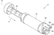
도 4는 토너 카트리지(9)의 일 실시예의 사시도이다. 도 4를 참조하면, 토너 카트리지(9)는 내부에 토너가 수용되고 토너가 배출되는 토너 배출부(94)를 구비하는 몸체(91)와, 토너를 토너 배출부(94)를 통하여 몸체(91)의 외부로 밀어내도록 몸체(91)에 마련되는 플런저(plunger)(93)를 구비하는 주사기형(syringe) 토너 리필 카트리지일 수 있다. 플런저(93)는 예를 들어, 몸체(91)에 길이방향(A)으로 이동가능하게 결합될 수 있다. 도 3에 도시된 바와 같이 토너 카트리지(9)가 토너 충전부(10)에 장착된 상태에서 플런저(93)를 길이방향(A)으로 누르면, 몸체(91)로부터 토너 충전부(10)를 통하여 현상 카트리지(2)의 토너 수용부(230)로 공급될 수 있다. 길이방향(A)은 제1회전축(C1)과 평행할 수 있다. 몸체(91)는 예를 들어 원통형일 수 있다. 제1회전축(C1)은 원통형 몸체의 중심축일 수 있다. 토너 카트리지(9)는 본체(1)와의 전기적 연결을 위한 전기 접점부(922)을 포함하는 메모리 유닛(921)을 구비할 수 있다. 메모리 유닛(921)은 홀더(92)에 탑재된다. 홀더(92)는 몸체(91)에 대하여 상대 회전 가능하게 몸체(91)에 연결된다.4 is a perspective view of one embodiment of the toner cartridge 9. Referring to FIG. 4, the toner cartridge 9 includes a body 91 including a toner discharge part 94 through which toner is received and toner is discharged, and a body 91 through the toner discharge part 94. It may be a syringe toner refill cartridge having a plunger (93) provided in the body (91) to push out of. The plunger 93 may be movably coupled to the body 91 in the longitudinal direction A, for example. As shown in FIG. 3, when the plunger 93 is pressed in the longitudinal direction A while the toner cartridge 9 is mounted in the toner charging unit 10, the developing cartridge is moved from the body 91 through the toner charging unit 10. It can be supplied to the toner container 230 of (2). The longitudinal direction A may be parallel to the first axis of rotation C1. Body 91 may be cylindrical, for example. The first rotating shaft C1 may be a central axis of the cylindrical body. The toner cartridge 9 may include a memory unit 921 including an electrical contact portion 922 for electrical connection with the main body 1. The memory unit 921 is mounted in the holder 92. The holder 92 is connected to the body 91 so as to be rotatable relative to the body 91.

토너 카트리지(9)가 토너 충전부(10)에 장착되면, 메모리유닛(921)은 본체(1)와 전기적으로 연결될 수 있다. 본체(1)는 메모리 유닛(921)과의 전기적 연결 여부, 예를 들어 메모리 유닛(921)과의 통신 가능 여부에 따라서 토너 카트리지(9)의 장착 여부를 판단할 수 있다. 메모리 유닛(921)은 토너 카트리지(9)의 상태를 모니터링 또는 관리하기 위한 회로부와, 본체(1)와의 연결을 위한 전기 접점부(922)를 포함할 수 있다. 회로부에는 예를 들어 자체 O/S(operating system)를 이용하여 본체(1)와의 사이에서 인증 및/또는 암호화 데이터 통신 중 적어도 하나를 수행하는 CPU(central process unit)를 포함하는 CRUM(customer replaceable unit monitor)부가 마련될 수 있다. 회로부에는 메모리가 더 포함할 수 있다. 메모리에는 토너 카트리지(9)에 대한 다양한 유형의 정보가 저장될 수 있다. 예를 들어, 메모리에는 제조사에 대한 정보, 제조일시에 대한 정보, 일련 번호, 모델 명 등과 같은 고유 정보, 각종 프로그램, 전자 서명 정보 및 사용 상태(예를 들어, 현재까지 몇 매를 인쇄하였는지, 인쇄 가능한 잔여 매수가 얼마인지, 토너 잔량이 얼마인지 등)에 대한 정보 등이 저장될 수 있다. 또한, 메모리에는 토너 카트리지(9)의 수명, 셋업 메뉴 등에 대한 정보까지 저장될 수 있다. 이외에도 회로부는 본체(1)와의 통신, 인증, 암호화 등을 위한 다양한 기능을 수행할 수 있는 기능블록을 포함할 수 있다. 회로부는 CPU를 포함하는 칩(chip)의 형태, 또는 메모리와 CPU를 포함하는 칩의 형태, 칩 및 다양한 기능 블록을 구현하기 위한 회로소자들이 실장된 인쇄회로기판의 형태로 구현될 수 있다. When the toner cartridge 9 is mounted in the toner charging unit 10, the memory unit 921 may be electrically connected to the main body 1. The main body 1 may determine whether the toner cartridge 9 is mounted according to whether the memory unit 921 is electrically connected, for example, whether or not the memory unit 921 can communicate with the memory unit 921. The memory unit 921 may include a circuit unit for monitoring or managing the state of the toner cartridge 9, and an electrical contact unit 922 for connection with the main body 1. The circuit portion includes, for example, a customer replaceable unit including a central process unit (CPU) that performs at least one of authentication and / or encrypted data communication with the main body 1 using its own operating system (O / S). monitor unit may be provided. The circuit unit may further include a memory. Various types of information about the toner cartridge 9 may be stored in the memory. For example, the memory contains unique information such as manufacturer information, manufacturing date and time, serial number, model name, etc., various programs, electronic signature information, and usage status (e.g., how many copies have been printed so far, Information on how much remaining number of sheets, how much remaining toner, etc. may be stored. In addition, information on the life of the toner cartridge 9, the setup menu, and the like may be stored in the memory. In addition, the circuit unit may include a function block capable of performing various functions for communication, authentication, encryption, and the like with the main body 1. The circuit unit may be implemented in the form of a chip including a CPU, or in the form of a printed circuit board on which a chip and a circuit element for implementing various functional blocks are implemented.

전기 접점부(922)는 도전성 패턴 형태, 모듈러 잭(modular jack) 형태, 탄력 단자 형태 등, 본체(1)와의 전기적 접속이 가능한 다양한 형태를 가질 수 있다. 본 실시예의 전기 접점부(922)는 도전성 패턴이다. 전기 접점부(922)는 홀더(92)의 외부로 노출된다. 전기 접점부(922)는 하나 이상의 전기 접점을 구비할 수 있다. 전기 접점부(922)는 회로부의 정보를 본체(1)로 전달하기 위한 데이터 전기 접점, 토너 충전 완료 신호를 본체(1)로 전달하기 위한 전기 접점, 토너 카트리지(9)의 토너 충전부(10)에의 장착 여부에 관한 신호를 본체(1)로 전달하기 위한 전기 접점 중 적어도 하나를 포함할 수 있다. The electrical contact portion 922 may have various shapes such as a conductive pattern shape, a modular jack shape, a resilient terminal shape, and the like, which may be electrically connected to the main body 1. The electrical contact portion 922 of this embodiment is a conductive pattern. The electrical contact 922 is exposed to the outside of the holder 92. The electrical contact portion 922 may have one or more electrical contacts. The electrical contact portion 922 includes a data electrical contact for transferring information of the circuit portion to the main body 1, an electrical contact for transmitting a toner charging completion signal to the main body 1, and a toner charging portion 10 of the toner cartridge 9. It may include at least one of the electrical contacts for transmitting to the body (1) a signal relating to whether or not mounting.

도 3을 참조하면, 토너 카트리지(9)가 토너 충전부(10)에 장착되면, 홀더(92)는 본체(1)에 마련된 연결부(100)에 수납된다. 연결부(100)에는 전기 접점부(922)와 전기적으로 연결되는 전기 단자부(도 9: 101)가 마련된다. Referring to FIG. 3, when the toner cartridge 9 is mounted in the toner charging part 10, the holder 92 is accommodated in the connection part 100 provided in the main body 1. The connection portion 100 is provided with an electrical terminal portion (FIG. 9: 101) electrically connected to the electrical contact portion 922.

토너 카트리지(9)는 토너 충전부(10)에 장착되어 제1회전축(C1)을 중심으로 장착 위치(B0)-제1각위치(B1)-제2각위치(B2)로 회전될 수 있다. 후술하겠지만, 장착 위치(B0), 제1각위치(B1), 제2각위치(B2)를 간략하게 정의한다. 장착 위치(B0)는 토너 카트리지(9)가 연통부(8)를 통하여 본체(1)에 삽입되어 토너 충전부(10)에 장착된 상태의 토너 카트리지(9)의 위치를 말한다. 제1각위치(B1)는 토너 카트리지(9)가 장착 위치(B0)로부터 제1각도만큼 회전된 위치를 말한다. 제2각위치(B2)는 토너 카트리지(9)가 제1각위치(B1)로부터 제2각도만큼 회전된 위치를 말한다. 장착 위치(B0)로부터 제1각위치(B1)까지의 토너 카트리지(9)의 회전을 제1회전, 제1각위치(B1)로부터 제2각위치(B2)까지의 토너 카트리지(9)의 회전을 제2회전이라 한다.The toner cartridge 9 may be mounted on the toner charging unit 10 and rotated to the mounting position B0, the first angular position B1, and the second angular position B2 about the first rotational axis C1. As will be described later, the mounting position B0, the first angular position B1, and the second angular position B2 are briefly defined. The mounting position B0 refers to the position of the toner cartridge 9 in which the toner cartridge 9 is inserted into the main body 1 through the communicating portion 8 and mounted in the toner charging portion 10. The first angle position B1 refers to a position where the toner cartridge 9 is rotated by the first angle from the mounting position B0. The second angular position B2 refers to a position where the toner cartridge 9 is rotated by a second angle from the first angular position B1. The rotation of the toner cartridge 9 from the mounting position B0 to the first angular position B1 is performed by the first rotation and the toner cartridge 9 from the first angular position B1 to the second angular position B2. Rotation is called a second rotation.

전술한 바와 같이, 토너 카트리지(9)는 토너 충전부(10)에 장착되어 장착위치(B0), 제1각위치(B1), 제2각위치(B2)로 회전된다. 메모리 유닛(921)과 본체(1)와의 안정적인 전기적 연결을 위하여, 홀더(92)는 몸체(91)에 상대회전될 수 있게 몸체(91)와 연결된다. 토너 카트리지(9)가 본체(1)에 장착되면, 홀더(92)는 연결부(100)에 수납된다. 연결부(100)는 토너 카트리지(9)가 회전될 때에 홀더(92)를 잡는다. 따라서, 홀더(92)는 연결부(100)에 수납된 상태로 유지되고, 몸체(91)만이 제1각위치(B1) 및 제2각위치(B2)로 회전된다. 이에 의하여, 본체(1)와 메모리 유닛(921)과의 안정적인 전기적 연결이 유지될 수 있다.As described above, the toner cartridge 9 is mounted on the toner charging unit 10 and rotated to the mounting position B0, the first angular position B1, and the second angular position B2. For a stable electrical connection between the memory unit 921 and the body 1, the holder 92 is connected to the body 91 so as to be relatively rotated to the body 91. When the toner cartridge 9 is mounted on the main body 1, the holder 92 is accommodated in the connecting portion 100. The connecting portion 100 holds the holder 92 when the toner cartridge 9 is rotated. Accordingly, the holder 92 is kept in the connection portion 100, and only the body 91 is rotated to the first angular position B1 and the second angular position B2. As a result, stable electrical connection between the main body 1 and the memory unit 921 may be maintained.

이하, 토너 카트리지(9)의 실시예와 토너 카트리지(9)와 토너 충전부(10)와의 인터페이스 구조(토너 리필 인터페이스 구조)의 실시예를 설명한다. An embodiment of the toner cartridge 9 and an embodiment of the interface structure (toner refill interface structure) between the toner cartridge 9 and the toner charging unit 10 will be described.

도 5는 토너 카트리지(9)의 일 실시예의 분해 사시도이다. 도 6은 홀더(92)가 홈 위치에 위치된 상태를 보여준다. 도 7은 홀더(92)가 회전된 위치에 위치된 상태를 보여준다. 도 8은 토너 충전부(10)의 일 실시예의 분해 사시도이다. 도 9는 토너 카트리지(9)가 장착 위치(B0)에 위치된 상태에서 제1토너 배출부(941), 제2토너 배출부(951), 잠금 부재(96), 홀더(92)의 위치관계를 보여준다. 도 10은 토너 카트리지(9)가 장착 위치(B0)에 위치된 상태에서 제2토너 배출부(951), 제2토너 유입부(141), 제1토너 유입부(121)의 위치관계를 보여준다. 도 11은 토너 카트리지(9)가 제1각위치(B1)에 위치된 상태에서 제1토너 배출부(941), 제2토너 배출부(951), 잠금 부재(96), 홀더(92)의 위치관계를 보여준다. 도 12는 토너 카트리지(9)가 제1각위치(B1)에 위치된 상태에서 제2토너 배출부(951), 제2토너 유입부(141), 제1토너 유입부(121)의 위치관계를 보여준다. 도 13은 토너 카트리지(9)가 제2각위치(B2)에 위치된 상태에서 제1토너 배출부(941), 제2토너 배출부(951), 잠금 부재(96), 홀더(92)의 위치관계를 보여준다. 도 14는 토너 카트리지(9)가 제2각위치(B2)에 위치된 상태에서 제2토너 배출부(951), 제2토너 유입부(141), 제1토너 유입부(121)의 위치관계를 보여준다. 5 is an exploded perspective view of one embodiment of the toner cartridge 9. 6 shows a state in which the holder 92 is located in the home position. 7 shows a state in which the holder 92 is positioned in the rotated position. 8 is an exploded perspective view of an embodiment of the toner charging unit 10. 9 shows the positional relationship of the first toner discharge part 941, the second toner discharge part 951, the locking member 96, and the holder 92 in a state where the toner cartridge 9 is located at the mounting position B0. Shows. 10 shows the positional relationship of the second toner discharge portion 951, the second toner inlet portion 141, and the first toner inlet portion 121 in the state where the toner cartridge 9 is located at the mounting position B0. . Fig. 11 shows the first toner discharge portion 941, the second toner discharge portion 951, the locking member 96, and the holder 92 in a state where the toner cartridge 9 is located at the first angle position B1. Show the positional relationship. 12 shows the positional relationship between the second toner discharge portion 951, the second toner inlet portion 141, and the first toner inlet portion 121 with the toner cartridge 9 positioned at the first angle position B1. Shows. Fig. 13 shows the first toner discharge portion 941, the second toner discharge portion 951, the locking member 96, and the holder 92 with the toner cartridge 9 positioned at the second angle position B2. Show the positional relationship. 14 shows the positional relationship between the second toner discharge portion 951, the second toner inlet portion 141, and the first toner inlet portion 121 with the toner cartridge 9 positioned at the second angle position B2. Shows.

먼저, 도 4, 도 5, 도 6, 및 도 7을 참조하면서 토너 카트리지(9)의 실시예를 상세히 설명한다. First, the embodiment of the toner cartridge 9 will be described in detail with reference to FIGS. 4, 5, 6, and 7.

도 4와 도 5를 참조하면, 전술한 바와 같이, 홀더(92)는 몸체(91)에 대하여 상대회전될 수 있게 몸체(91)에 결합된다. 홀더(92)는 몸체(91)에 대하여 홈 위치(도 6)와 회전된 위치(도 7)로 상대회전될 수 있다. 홀더(92)가 홈 위치에 위치된 상태에서 토너 카트리지(9)는 토너 충전부(10)에 장착되며, 홀더(92)는 본체(1)에 마련된 연결부(100)에 수압된다. 회전된 위치는 토너 카트리지(9)의 제2각위치(B2)에 대응될 수 있다. 따라서, 홈 위치와 회전된 위치 사이의 각 간격은 장착 위치(B0)와 제2각 위치(B2) 사이의 각 간격과 동일할 수 있다. 홈 위치와 회전된 위치 사이의 각 간격은 예를 들어 180도 일 수 있다. 4 and 5, as described above, the holder 92 is coupled to the body 91 to be rotated relative to the body 91. The holder 92 may be rotated relative to the body 91 in a home position (FIG. 6) and in a rotated position (FIG. 7). The toner cartridge 9 is mounted in the toner charging section 10 with the holder 92 in the home position, and the holder 92 is pressurized by the connecting section 100 provided in the main body 1. The rotated position may correspond to the second angular position B2 of the toner cartridge 9. Thus, each interval between the home position and the rotated position may be equal to the respective interval between the mounting position B0 and the second angle position B2. Each interval between the home position and the rotated position may be 180 degrees, for example.

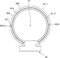
홀더(92)는 제1회전축(C1)을 중심으로 몸체(91)에 대하여 상대회전될 수 있다. 홀더(92)는 몸체(91)에 회전될 수 있게 결합되는 원통부(923)와, 메모리 유닛(921)을 수납하는 수납부(924)와, 수납부(924)를 덮는 덮개(925)를 구비할 수 있다. 수납부(924)는 원통부(923)의 외주부로부터 길이방향(A)으로 연장된 형태일 수 있다. 메모리 유닛(921)의 전기 접점부(922)는 덮개(925)에 마련된 개구부(925-1)를 통하여 외부로 노출될 수 있다. The holder 92 may be rotated relative to the body 91 about the first rotation shaft C1. The holder 92 includes a cylindrical portion 923 rotatably coupled to the body 91, an accommodating portion 924 for accommodating the memory unit 921, and a lid 925 covering the accommodating portion 924. It can be provided. The accommodation part 924 may have a form extending in the longitudinal direction A from the outer circumferential part of the cylindrical part 923. The electrical contact portion 922 of the memory unit 921 may be exposed to the outside through the opening 925-1 provided in the cover 925.

일 예로서, 몸체(91)는 토너가 수용된 제1몸체(91-1)와, 제1몸체(91-1)의 선단부에 결합되는 제2몸체(91-2)를 구비할 수 있다. 예를 들어, 제1몸체(91-1)와 제2몸체(91-2)는 스냅-핏 결합될 수 있다. 이를 위하여, 제1몸체(91-1)에는 후크(913-1)가 마련되고 제2몸체(91-2)에는 후크(913-1)가 걸리는 걸림홈(913-2)이 마련될 수 있다. 홀더(92)는 제2몸체(91-2)에 회전될 수 있게 지지될 수 있다. 제2몸체(91-2)에는 원통형 외주부(916)가 마련된다. 홀더(92)의 원통부(923)는 원통형 외주부(916)에 회전될 수 있게 삽입될 수 있다. As an example, the body 91 may include a first body 91-1 in which toner is accommodated, and a second body 91-2 coupled to the front end of the first body 91-1. For example, the first body 91-1 and the second body 91-2 may be snap-fit coupled. To this end, a hook 913-1 may be provided in the first body 91-1, and a locking groove 913-2 in which the hook 913-1 is engaged may be provided in the second body 91-2. . The holder 92 may be supported to be rotatable to the second body 91-2. The second body 91-2 is provided with a cylindrical outer periphery 916. The cylindrical portion 923 of the holder 92 may be inserted to be rotated to the cylindrical outer peripheral portion 916.

토너 카트리지(9)는 홀더(92)에 회전된 위치로부터 홈 위치로 복귀되는 방향으로 회전되도록 탄성력을 제공하는 탄성 부재(929)를 구비할 수 있다. 탄성 부재(929)는 다양한 형태로 구현될 수 있다. 본 실시예에서, 탄성 부재(929)는 일단부(929-1)가 제2몸체(91-2)에 지지되고 타단부(929-2)는 홀더(92)에 지지되는 토션 코일 스프링에 의하여 구현된다. 탄성 부재(920)에 의하여 홀더(92)는 토너 충전부(10)에 장착되지 않은 상태에서 홈 위치에 유지될 수 있다. 따라서, 토너 카트리지(9)를 토너 충전부(10)에 장착할 때에 홀더(92)가 자연스럽게 본체(1)에 마련된 연결부(100)에 수납될 수 있다. The toner cartridge 9 may be provided with an elastic member 929 which provides an elastic force so that the holder 92 rotates in the direction from the rotated position to the home position. The elastic member 929 may be implemented in various forms. In this embodiment, the elastic member 929 is supported by a torsion coil spring whose one end 929-1 is supported by the second body 91-2 and the other end 929-2 is supported by the holder 92. Is implemented. The holder 92 can be held in the home position by the elastic member 920 in a state where the holder 92 is not attached to the toner filling unit 10. Therefore, when mounting the toner cartridge 9 to the toner charging unit 10, the holder 92 can be naturally accommodated in the connecting portion 100 provided in the main body (1).

토너 카트리지(9)는 홀더(92)가 홈 위치를 넘어서 회전되지 않도록 하는 회전 방지 유닛을 포함할 수 있다. 회전 방지 유닛은 탄성 부재(929)의 탄성력에 의하여 홀더(92)가 홈 위치로 복귀될 때에 홈 위치를 넘어서 회전되지 않도록 한다. 회전 방지 유닛은 홀더(92)가 회전된 위치를 넘어서 회전되지 않도록 할 수 있다. 일 예로서, 회전 방지 유닛은 규제 슬롯과, 규제 슬롯에 걸리는스토퍼의 조합에 의하여 구현될 수 있다. 상기 회전 방지 유닛은, 몸체(91)와 홀더(92) 중 어느 하*에 마련되고 홈 위치와 회전된 위치에 각각 대응되는 제1단부(926-1)와 제2단부(926-2)를 구비하는 규제 슬롯(926)과, 몸체(91)와 홀더(92) 중 다른 하나에 마련되고 홈 위치와 회전된 위치에서 제1단부(926-1)와 제2단부(926-2)에 걸리는 스토퍼(917)를 포함할 수 있다. 예를 들어, 홀더(92)에 규제 슬롯(926)이 마련되고, 몸체(91)에 스토퍼(917)가 마련될 수 있으며, 그 반대일 수도 있다. The toner cartridge 9 may include a rotation preventing unit that prevents the holder 92 from rotating beyond the home position. The anti-rotation unit prevents the holder 92 from rotating beyond the home position when the holder 92 is returned to the home position by the elastic force of the elastic member 929. The anti-rotation unit can prevent the holder 92 from rotating beyond the rotated position. As an example, the anti-rotation unit may be implemented by a combination of a regulating slot and a stopper hanging over the regulating slot. The anti-rotation unit may include a first end 926-1 and a second end 926-2 provided at any one of the body 91 and the holder 92 and respectively correspond to the home position and the rotated position. It is provided on the other side of the regulating slot 926 and the body 91 and the holder 92, which is provided with the first end 926-1 and the second end 926-2 in the home position and the rotated position It may include a stopper 917. For example, the regulating slot 926 may be provided in the holder 92, the stopper 917 may be provided in the body 91, and vice versa.

도 5, 도 6, 도 7을 참조하면, 규제 슬롯(926)은 원통부(923)에 절개되어 형성될 수 있다. 제1단부(926-1)와 제2단부(926-2) 사이의 각 간격은 홈 위치와 회전된 위치 사이의 각 간격과 동일할 수 있다. 스토퍼(917)는 제2몸체(91-2)의 원통형 외주부(916)에 마련될 수 있다. 스토퍼(917)는 원통형 외주부(916)로부터 반경 방향으로 외측으로 돌출되어 규제 슬롯(926)에 삽입된다. 스토퍼(917)가 규제 슬롯(926)에 삽입됨으로써, 홀더(92)의 몸체(91), 즉 제2몸체(91-2)에 대한 제1회전축(C1) 방향으로의 이동이 제한되며, 홀더(92)가 제2몸체(91-2)에 회전될 수 있게 지지될 수 있다. 따라서, 규제 슬롯(926)과 스토퍼(917)는 홀더(92)가 몸체(91), 즉 제2몸체(91-2)로부터 이탈되지 않도록 하는 이탈 방지 유닛으로 기능할 수 있다. 5, 6, and 7, the restricting slot 926 may be formed by being cut in the cylindrical portion 923. Each gap between the first end 926-1 and the second end 926-2 may be equal to the gap between the home position and the rotated position. The stopper 917 may be provided on the cylindrical outer circumferential portion 916 of the second body 91-2. The stopper 917 protrudes radially outward from the cylindrical outer peripheral portion 916 and is inserted into the regulation slot 926. As the stopper 917 is inserted into the regulation slot 926, the movement of the holder 92 in the direction of the first rotational axis C1 with respect to the body 91, that is, the second body 91-2, is restricted. 92 may be supported to rotate on the second body 91-2. Accordingly, the restricting slot 926 and the stopper 917 can function as a release preventing unit that prevents the holder 92 from being separated from the body 91, that is, the second body 91-2.

도 6에 도시된 바와 같이, 홀더(92)가 홈 위치에 위치되면, 스토퍼(917)가 규제 슬롯(926)의 제1단부(926-1)에 걸리고, 홀더(92)는 홈 위치를 넘어서 몸체(91)에 대하여 회전될 수 없다. 탄성 부재(929)의 탄성력에 의하여 홀더(92)는 홈 위치에 유지된다. 따라서, 토너 충전부(10)로부터 분리된 상태에서는 홀더(92)가 항상 홈 위치에 위치되며, 이 상태에서 토너 카트리지(9)를 바로 토너 충전부(10)에 장착할 수 있다. As shown in FIG. 6, when the holder 92 is in the home position, the stopper 917 is caught in the first end 926-1 of the regulating slot 926, and the holder 92 is beyond the home position. It cannot be rotated relative to the body 91. The holder 92 is held in the home position by the elastic force of the elastic member 929. Therefore, the holder 92 is always positioned at the home position in the state where it is separated from the toner charging unit 10, and in this state, the toner cartridge 9 can be directly attached to the toner charging unit 10.

도 7에 도시된 바와 같이, 홀더(92)가 회전된 위치에 위치되면, 스토퍼(917)가 규제 슬롯(926)의 제2단부(926-2)에 걸리고, 홀더(92)는 회전된 위치를 넘어서 몸체(91)에 대하여 회전될 수 없다. As shown in FIG. 7, when the holder 92 is positioned in the rotated position, the stopper 917 is caught by the second end 926-2 of the regulating slot 926, and the holder 92 is rotated in position. It cannot be rotated relative to the body 91 beyond.

다시, 도 4와 도 5를 참조하면, 토너 카트리지(9)는 토너 배출부(94)를 개방하는 배출 위치와 토너 배출부(94)를 막는 폐쇄 위치로 회전 가능하게 몸체(91)에 설치되는 배출 셔터(95)를 구비할 수 있다. 4 and 5, the toner cartridge 9 is rotatably installed in the body 91 to a discharge position for opening the toner discharge portion 94 and a closed position for blocking the toner discharge portion 94. FIG. A discharge shutter 95 may be provided.

일 예로서, 토너 배출부(94)는 몸체(91)의 외부로 연장되어 토너 카트리지(9)가 토너 충전부(10)에 장착되면 후술하는 유입 셔터(도 8: 14)의 제2토너 유입부(도 8: 141)에 삽입될 수 있다. 토너 배출부(94)는 몸체(91)에 마련되는 제1토너 배출부(941)와 배출 셔터(95)에 마련되는 제2토너 배출부(951)를 구비할 수 있다. 배출 셔터(95)는, 폐쇄 위치(도 9)에서 제1토너 배출부(941)를 막으며, 배출 위치(도 13)에서 제1토너 배출부(941)를 개방한다. 예를 들어, 배출 위치에서 제1토너 배출부(941)와 제2토너 배출부(951)가 서로 정렬되며, 폐쇄 위치에서 제1토너 배출부(941)와 제2토너 배출부(951)가 서로 어긋나서 제1토너 배출부(941)가 배출 셔터(95)에 의하여 막힌다. 홀더(92)와 배출 셔터(95)와 동일한 회전축을 중심으로 몸체(91)에 대하여 상대 회전될 수 있다. 배출 셔터(95)는 폐쇄 위치와 배출 위치로 제1회전축(C1)을 중심으로 몸체(91)에 대하여 상대 회전될 수 있다. 제1토너 배출부(941)와 제2토너 배출부(951)는 제1회전축(C1)으로부터 반경 방향으로 동일한 거리만큼 편심되게 위치될 수 있다. As an example, when the toner discharge part 94 extends outside the body 91 so that the toner cartridge 9 is mounted in the toner charging part 10, the second toner inlet part of the inflow shutter (FIG. 8: 14) described later will be described. (FIG. 8: 141). The toner discharge part 94 may include a first toner discharge part 941 provided in the body 91 and a second toner discharge part 951 provided in the discharge shutter 95. The discharge shutter 95 blocks the first toner discharge portion 941 in the closed position (FIG. 9) and opens the first toner discharge portion 941 in the discharge position (FIG. 13). For example, the first toner discharge portion 941 and the second toner discharge portion 951 are aligned with each other in the discharge position, and the first toner discharge portion 941 and the second toner discharge portion 951 are aligned in the closed position. The first toner discharge portion 941 is blocked by the discharge shutter 95 by shifting from each other. It can be rotated relative to the body 91 about the same rotation axis as the holder 92 and the discharge shutter (95). The discharge shutter 95 may be rotated relative to the body 91 about the first rotating shaft C1 in the closed position and the discharge position. The first toner discharge unit 941 and the second toner discharge unit 951 may be eccentrically positioned by the same distance in the radial direction from the first rotation shaft C1.

제1토너 배출부(941)는 제1몸체(91-1)에 마련될 수 있다. 배출 셔터(95)는 제1몸체(91-1)와 제2몸체(91-2) 사이에 위치될 수 있다. 제1토너 배출부(941)는 제1몸체(91-1)로부터 배출 셔터(95)를 향하여 연장된 형태일 수 있다. 배출 셔터(95)는 예를 들어, 제2몸체(91-2)에 회전될 수 있게 지지될 수 있다. 예를 들어, 제2몸체(91-2)에 제1회전축(C1)을 중심으로 하는 원통형의 외측 지지부(912)가 마련되고, 배출 셔터(95)에 외측 지지부(912)의 내측에 회전될 수 있게 지지되는 내측 지지부(952)가 마련될 수 있다. The first toner discharge part 941 may be provided in the first body 91-1. The discharge shutter 95 may be located between the first body 91-1 and the second body 91-2. The first toner discharge part 941 may extend from the first body 91-1 toward the discharge shutter 95. The discharge shutter 95 may be supported to be rotatable to the second body 91-2, for example. For example, a cylindrical outer support 912 is provided on the second body 91-2 about the first rotational axis C1, and the discharge shutter 95 is rotated inside the outer support 912. An inner support 952 may be provided that can be supported.

일 예로서, 토너 배출부(94)는 몸체(91)의 외부로 돌출되어 토너 카트리지(9)가 토너 충전부(10)에 장착되면 후술하는 유입 셔터(도 8: 14)의 제2토너 유입부(도 8: 141)에 삽입될 수 있다. 제2토너 배출부(951)는 몸체(91)의 외부로 연장되어 몸체(91) 외부로 돌출될 수 있다. 제2몸체(91-2)에 제2토너 배출부(951)가 제2몸체(91-2)의 외부로 돌출될 수 있도록 관통된 제2슬롯(911)이 마련된다. 제2슬롯(911)은 몸체(91)의 배출 셔터(95)에 대한 상대 회전 각도를 제한하는 제2회전 제한부로서 기능할 수 있다. 제2슬롯(911)은 몸체(91)의 배출 셔터(95)에 대한 상대 회전 각도를 제한할 수 있도록 제1회전축(C1)을 중심으로 하는 원호 형태일 수 있다. 제2슬롯(911)의 일단부와 타단부는 각각 배출 셔터(95)의 폐쇄 위치와 배출 위치에 대응될 수 있다. 배출 셔터(95)가 폐쇄 위치에 도달되면, 제2토너 배출부(951)가 제2슬롯(911)의 일단부에 걸린다. 배출 셔터(95)가 배출 위치에 도달되면, 제2슬롯(911)의 타단부가 제2토너 배출부(951)에 걸린다. 따라서, 몸체(91)는 배출 셔터(95)에 대하여 더이상 상대 회전되지 않는다.As an example, when the toner discharge part 94 protrudes to the outside of the body 91 so that the toner cartridge 9 is mounted on the toner charging part 10, the second toner inlet part of the inflow shutter (FIG. 8: 14) described later will be described. (FIG. 8: 141). The second toner discharge part 951 may extend to the outside of the body 91 to protrude to the outside of the body 91. A second slot 911 is provided in the second body 91-2 so that the second toner discharge part 951 may protrude to the outside of the second body 91-2. The second slot 911 may function as a second rotation limiting unit that limits the relative rotation angle of the body 91 with respect to the discharge shutter 95. The second slot 911 may have a circular arc shape centering on the first rotation shaft C1 to limit the relative rotation angle of the body 91 with respect to the discharge shutter 95. One end and the other end of the second slot 911 may correspond to the closed position and the discharge position of the discharge shutter 95, respectively. When the discharge shutter 95 reaches the closed position, the second toner discharge portion 951 is caught at one end of the second slot 911. When the discharge shutter 95 reaches the discharge position, the other end of the second slot 911 is caught by the second toner discharge portion 951. Thus, the body 91 is no longer rotated relative to the discharge shutter 95.

제1몸체(91-1)와 배출 셔터(95) 사이에는 제1씰링 부재(98)가 개재될 수 있다. 제1씰링 부재(98)는 배출 셔터(95)와 함께 몸체(91)에 대하여 상대 회전될 수 있다. 제1씰링 부재(98)에는 제2토너 배출부(951)와 정렬된 관통공(981)이 마련된다. 제1씰링 부재(98)는 배출 셔터(95)의 폐쇄 위치와 배출 위치 사이에서 제1토너 배출부(941)를 막는다. 배출 셔터(95)가 배출 위치에 위치되면, 제1토너 배출부(941), 관통공(981), 제2토너 배출부(951)가 서로 정렬되어 몸체(91)로부터 외부로 토너가 배출될 수 있다. 배출 셔터(95)가 배출 위치로부터 벗어나면, 제1토너 배출부(941)가 제1씰링 부재(98)에 의하여 막힌다. 제1씰링 부재(98)를 채용함으로써, 제1몸체(91-1)와 배출 셔터(95) 사이에서의 토너 누출을 방지할 수 있다. The first sealing member 98 may be interposed between the first body 91-1 and the discharge shutter 95. The first sealing member 98 may be rotated relative to the body 91 together with the discharge shutter 95. The first sealing member 98 is provided with a through hole 981 aligned with the second toner discharge portion 951. The first sealing member 98 blocks the first toner discharge portion 941 between the closed position and the discharge position of the discharge shutter 95. When the discharge shutter 95 is positioned at the discharge position, the first toner discharge portion 941, the through hole 981, and the second toner discharge portion 951 are aligned with each other so that toner can be discharged from the body 91 to the outside. Can be. When the discharge shutter 95 is out of the discharge position, the first toner discharge portion 941 is blocked by the first sealing member 98. By employing the first sealing member 98, toner leakage between the first body 91-1 and the discharge shutter 95 can be prevented.

토너 카트리지(9)는 배출 셔터(95)를 폐쇄 위치에 선택적으로 로킹시키는 잠금 부재(96)를 구비할 수 있다. 잠금 부재(96)는 토너 카트리지(9)의 제1회전 동안, 즉 장착 위치(B0)로부터 제1각위치(B1)까지의 회전 동안에 배출 셔터(95)를 폐쇄 위치에 로킹시킨다. 예를 들어, 배출 셔터(95)에는 제1간섭부(953)가 마련될 수 있다. 잠금 부재(96)는 제1간섭부(953)에 대응되는 제2간섭부(963)를 구비할 수 있다. 잠금 부재(96)는 폐쇄 위치에 위치된 배출 셔터(95)의 제1간섭부(953)가 제2간섭부(963)에 걸려 배출 셔터(95)의 회전을 불허하는 잠금 위치(도 9)와, 배출 셔터(95)의 회전을 허용하는 해제 위치(도 11)로 제1회전축(C1)과 다른 제2회전축(C2)을 중심으로 회전될 수 있게 몸체(91)에 지지될 수 있다. 잠금 스프링(97)은 잠금 부재(96)에 해제 위치로부터 잠금 위치로 복귀되는 방향의 탄성력을 제공한다. 잠금 스프링(97)은 잠금 부재(96)에 배출 셔터(95)를 폐쇄 위치에 로킹시키는 방향의 탄성력을 가할 수 있다. 잠금 부재(96)가 잠금 위치에 위치된 상태에서는 제1간섭부(953)가 제2간섭부(963)에 걸리므로, 배출 셔터(95)는 배출 위치로 회전될 수 없으며, 폐쇄 위치에 유지된다. 잠금 부재(96)는 토너 카트리지(9)가 토너 충전부(10)에 장착되기 전에는 배출 셔터(95)를 폐쇄 위치에 위치된 상태에서 잠근다. 이에 의하여, 의도하지 않은 토너의 누출이 방지될 수 있다. 잠금 부재(96)가 해제 위치에 위치되면, 제2간섭부(963)가 제1간섭부(953)로부터 이격되고, 배출 셔터(95)는 폐쇄 위치로부터 배출 위치로 회전될 수 있다. The toner cartridge 9 may be provided with a locking member 96 for selectively locking the discharge shutter 95 in the closed position. The locking member 96 locks the discharge shutter 95 in the closed position during the first rotation of the toner cartridge 9, that is, during the rotation from the mounting position B0 to the first angular position B1. For example, the first interference part 953 may be provided in the discharge shutter 95. The locking member 96 may include a second interference portion 963 corresponding to the first interference portion 953. The locking member 96 has a locking position in which the first interference portion 953 of the discharge shutter 95 positioned in the closed position is caught by the second interference portion 963 to disallow rotation of the discharge shutter 95 (FIG. 9). And the body 91 to be rotated about the second rotation shaft C2 different from the first rotation shaft C1 to a release position (FIG. 11) to allow rotation of the discharge shutter 95. The locking spring 97 provides the locking member 96 with an elastic force in the direction from the release position to the lock position. The locking spring 97 may apply an elastic force to the locking member 96 in the direction of locking the discharge shutter 95 in the closed position. Since the first interference portion 953 is caught by the second interference portion 963 in the state where the locking member 96 is located in the locked position, the discharge shutter 95 cannot be rotated to the discharge position and is kept in the closed position. do. The locking member 96 locks the discharge shutter 95 in the closed position before the toner cartridge 9 is mounted in the toner charging section 10. By this, unintended leakage of the toner can be prevented. When the locking member 96 is positioned in the release position, the second interference portion 963 is spaced apart from the first interference portion 953, and the discharge shutter 95 can be rotated from the closed position to the discharge position.

일 예로서, 잠금 부재(96)에는 제2회전축(C2)을 따라 연장되고 일단부가 제2몸체(91-2)에 회전될 수 있게 지지된 지지축(964)을 구비할 수 있다. 제2몸체(91-2)에는 지지축(964)의 일단부가 삽입되어 회전될 수 있게 지지되는 지지공(914)이 마련될 수 있다. 배출 셔터(95)에는 지지축(964)의 타단부가 회전될 수 있게 지지되는 지지부(954)가 마련된다. 배출 셔터(95)가 제1회전축(C1)을 중심으로 폐쇄 위치와 배출 위치로 회전되므로, 이는 잠금 부재(96)는 배출 셔터(95)에 대하여 제1회전축(C1)을 중심으로 상대 회전되는 것과 같다. 따라서, 지지부(954)는 잠금 부재(96)의 제1회전축(C1)에 대한 상대 회전을 허용하는 원호 형태일 수 있다. 지지부(954)는 지지축(964)의 일단부가 지지공(914)으로부터 이탈되지 않도록 지지축(964)의 타단부를 지지한다. 이와 같은 구성에 의하면, 지지축(964)의 일단부가 지지공(914)으로부터 이탈되지 않도록 하기 위한 별도의 지지부재를 채용하지 않을 수 있으므로, 토너 카트리지(9)의 구조가 간단해지고 조립의 공정이 줄어들어 토너 카트리지(9)의 비용이 절감될 수 있다. As an example, the locking member 96 may include a support shaft 964 extending along the second rotation shaft C2 and having one end supported by the second body 91-2. The second body 91-2 may be provided with a support hole 914 to which one end of the support shaft 964 is inserted and rotated. The discharge shutter 95 is provided with a support part 954 which is supported to rotate the other end of the support shaft 964. Since the discharge shutter 95 is rotated to the closed position and the discharge position about the first rotational axis C1, this means that the locking member 96 is rotated relative to the first rotational axis C1 with respect to the discharge shutter 95. Same as Thus, the support 954 may be in the form of an arc that allows relative rotation of the locking member 96 about the first rotational axis C1. The support part 954 supports the other end of the support shaft 964 so that one end of the support shaft 964 is not separated from the support hole 914. According to such a structure, since a separate support member for preventing one end of the support shaft 964 from being detached from the support hole 914 may not be employed, the structure of the toner cartridge 9 is simplified and the assembly process is performed. By reducing the cost of the toner cartridge 9 can be reduced.

잠금 부재(96)는 잠금 위치로부터 해제 위치로 전환시키는 외력을 받도록 몸체(91)의 외부로 노출된 외력 수용부(965)를 구비할 수 있다. 예를 들어, 제2몸체(91-2)의 측부에 관통홈(915)이 마련되고, 외력 수용부(965)는 관통홈(915)을 통하여 제2몸체(91-2)의 외부로 노출될 수 있다. 외력 수용부(965)는 예를 들어 토너 카트리지(9)가 토너 충전부(10)에 장착되면, 토너 충전부(10)에 마련된 해제부(도 11: 131)와 간섭될 수 있다. 토너 카트리지(9)는 토너 충전부(10)에 장착되어 제1회전축(C1)을 중심으로 회전된다. 토너 카트리지(9)가 제1각위치(B1)에 도달되면, 외력 수용부(965)가 해제부(131)와 간섭되어 잠금 부재(96)는 잠금 위치로부터 해제 위치로 전환되며, 배출 셔터(95)의 로킹이 해제될 수 있다. The locking member 96 may have an external force receiving portion 965 exposed to the outside of the body 91 to receive an external force that switches from the locked position to the unlocked position. For example, the through groove 915 is provided on the side of the second body 91-2, and the external force receiving part 965 is exposed to the outside of the second body 91-2 through the through groove 915. Can be. The external force receiving portion 965 may interfere with the release portion (FIG. 11: 131) provided in the toner filling portion 10, for example, when the toner cartridge 9 is mounted in the toner filling portion 10. The toner cartridge 9 is mounted on the toner charging unit 10 to be rotated about the first rotating shaft C1. When the toner cartridge 9 reaches the first angle position B1, the external force receiving portion 965 interferes with the release portion 131 so that the locking member 96 is switched from the locked position to the unlocked position, and the discharge shutter ( 95) can be unlocked.

잠금 스프링(97)은 예를 들어, 코일 스프링, 리프 스프링, 잠금 부재(96)와 일체로 형성되는 탄력 아암 등 다양한 형태로 구현될 수 있다. 본 실시예에서, 잠금 부재(96)는 중앙의 코일감김부가 지지축(964)에 설치되고 일단부가 잠금 부재(96)에 지지되고 타단부가 제2몸체(91-2)에 지지되는 토션 코일 스프링에 의하여 구현된다.The locking spring 97 may be implemented in various forms such as, for example, a coil spring, a leaf spring, and an elastic arm integrally formed with the locking member 96. In this embodiment, the locking member 96 is a torsion in which a coil winding part in the center is installed on the support shaft 964, one end of which is supported by the locking member 96, and the other end of which is supported by the second body 91-2. It is implemented by a coil spring.

이하에서, 토너 카트리지(9)와 토너 충전부(10)와의 인터페이스 구조의 실시예에 대하여 설명한다. An embodiment of the interface structure between the toner cartridge 9 and the toner charging section 10 will be described below.

토너 리필 인터페이스 구조는 토너 카트리지(9)와, 토너 충전부(10)와, 연결부(100)를 포함할 수 있다. 도 3에 도시된 바와 같이, 연결부(100)는 본체(1)에 마련된다. 토너 충전부(10)는 현상 카트리지(2)와 일체로 형성되며, 현상 카트리지(2)와 함께 본체(1)에 착탈될 수 있다. 현상 카트리지(2)가 본체(1)에 장착되면, 토너 충전부(10)와 연결부(100)가 서로 인접하게 위치된다.The toner refill interface structure may include a toner cartridge 9, a toner charging unit 10, and a connecting unit 100. As shown in FIG. 3, the connection part 100 is provided in the main body 1. The toner charging part 10 is formed integrally with the developing cartridge 2, and can be attached to or detached from the main body 1 together with the developing cartridge 2. When the development cartridge 2 is mounted on the main body 1, the toner charging portion 10 and the connecting portion 100 are positioned adjacent to each other.

도 8을 참조하면, 토너 충전부(10)는 토너 카트리지(9)가 장착되는 장착부(11)와, 제1토너 유입부(121)와, 유입 셔터(14)를 구비할 수 있다. Referring to FIG. 8, the toner charging unit 10 may include a mounting unit 11 on which the toner cartridge 9 is mounted, a first toner inlet 121, and an inlet shutter 14.

장착부(11)는 토너 카트리지(9)가 장착된 상태에서 제1회전축(C1)에 대하여 회전될 수 있는 구조를 갖는다. 제1토너 유입부(121)는 토너 카트리지(9)로부터 토너를 받도록 장착부(11)에 마련된다. 예를 들어, 장착부(11)는 하부 몸체(12)와 상부 몸체(13)를 구비할 수 있다. 상부 몸체(13)는 하부 몸체(12)에 결합된다. 상부 몸체(13)는 토너 카트리지(9)가 회전될 수 있게 지지될 수 있는 구조를 갖는다. 예를 들어, 상부 몸체(13)에는 토너 카트리지(9)의 선단부를 수용하는 원통형의 제1수용부(132)가 마련된다. 제1수용부(132)는 예를 들어 제1회전축(C1)을 중심으로 하고 상방으로 돌출된 원통형 리브에 의하여 구현될 수 있다. 하부 몸체(12)는 토너 수용부(230)와 연결된다. 제1토너 유입부(121)는 하부 몸체(12)에 마련된다. 장착부(11)에는 해제부(131)가 마련될 수 있다. 해제부(131)는 토너 카트리지(9)가 제1각위치에 위치된 때에 잠금 부재(96)와 간섭되어, 몸체(91)가 배출 셔터(95)에 대하여 제1각위치(B1)로부터 제1, 제2토너 배출부(941)(951)가 서로 정렬된 제2각위치(B2)로 상대 회전될 수 있도록, 배출 셔터(95)의 로킹을 해제시킨다. 예를 들어, 제1수용부(132)는 부분적으로 반경 방향으로 외측으로 확장되며, 이에 의하여 제1수용부(132)보다 직경이 큰 제2수용부(133)가 형성된다. 제1회전축(C1)에 대한 제2수용부(133)의 직경은 잠금 부재(96)의 외력 수용부(965)가 간섭되지 않도록 결정된다. 해제부(131)는 제1수용부(132)와 제2수용부(133)의 경계에 의하여 구현될 수 있다.The mounting portion 11 has a structure that can be rotated with respect to the first rotating shaft C1 in a state where the toner cartridge 9 is mounted. The first toner inlet 121 is provided in the mounting portion 11 to receive the toner from the toner cartridge 9. For example, the mounting portion 11 may include a lower body 12 and an upper body 13. The upper body 13 is coupled to the lower body 12. The upper body 13 has a structure in which the toner cartridge 9 can be supported to be rotated. For example, the upper body 13 is provided with a cylindrical first accommodating portion 132 for accommodating the distal end of the toner cartridge 9. The first accommodating part 132 may be implemented by, for example, a cylindrical rib protruding upward with respect to the first rotational axis C1. The lower body 12 is connected to the toner container 230. The first toner inlet 121 is provided in the lower body 12. The mounting part 11 may be provided with a release part 131. The release portion 131 interferes with the locking member 96 when the toner cartridge 9 is positioned in the first angular position, such that the body 91 is removed from the first angular position B1 with respect to the discharge shutter 95. The first and second toner discharge parts 941 and 951 are released to unlock the discharge shutter 95 so that the second toner discharge parts 941 and 951 can be relatively rotated to the second angle positions B2 aligned with each other. For example, the first accommodating part 132 partially extends outward in the radial direction, whereby a second accommodating part 133 having a larger diameter than the first accommodating part 132 is formed. The diameter of the second accommodation portion 133 relative to the first rotation shaft C1 is determined so that the external force receiving portion 965 of the locking member 96 does not interfere. The release part 131 may be implemented by the boundary between the first accommodating part 132 and the second accommodating part 133.

유입 셔터(14)는 제1토너 유입부(121)를 막는 차단위치(도 10)와 제1토너 유입부(121)를 개방하는 유입 위치(도 12)로 전환될 수 있게 장착부(11)에 마련된다. 유입 셔터(14)는 제1회전축(C1)에 대하여 차단 위치와 유입 위치로 회전될 수 있다. 일 예로서, 유입 셔터(14)는 제2토너 유입부(141)를 구비할 수 있다. 차단 위치에서, 제1토너 유입부(121)와 제2토너 유입부(141)가 서로 어긋나서 제1토너 유입부(121)가 막힌다. 유입 위치에서, 제1토너 유입부(121)와 제2토너 유입부(141)가 서로 정렬되어 제1토너 유입부(121)가 개방된다. The inflow shutter 14 is mounted to the mounting portion 11 so as to be switched to a blocking position (FIG. 10) that blocks the first toner inlet 121 and an inlet position (FIG. 12) that opens the first toner inlet 121. To be prepared. The inflow shutter 14 may be rotated to the blocking position and the inflow position with respect to the first rotation shaft C1. As an example, the inflow shutter 14 may include a second toner inlet 141. In the blocking position, the first toner inlet 121 and the second toner inlet 141 are shifted from each other so that the first toner inlet 121 is blocked. In the inflow position, the first toner inlet 121 and the second toner inlet 141 are aligned with each other to open the first toner inlet 121.

유입 셔터(14)는 하부 몸체(12)와 상부 몸체(13) 사이에 위치될 수 있다. 유입 셔터(14)는 하부 몸체(12)에 회전될 수 있게 지지될 수 있다. 하부 몸체(12)에는 유입 셔터(14)를 제1회전축(C1)을 중심으로 회전될 수 있게 지지하는 제1원통부(122)가 마련된다. 제1원통부(122)는 예를 들어 제1회전축(C1)을 중심으로 하고 상부 몸체(13) 쪽으로 돌출된 원통형 리브에 의하여 구현될 수 있다. 유입 셔터(14)는 그 외주를 형성하는 제2원통부(142)가 제1원통부(122)의 내측에 위치되도록 하부 몸체(12)에 지지된다. 상부 몸체(13)는 유입 셔터(14)를 덮도록 하부 몸체(12)에 결합된다.The inlet shutter 14 can be located between the lower body 12 and the upper body 13. The inlet shutter 14 can be supported to be rotatable to the lower body 12. The lower body 12 is provided with a first cylindrical portion 122 for supporting the inflow shutter 14 so as to be rotated about the first rotational axis C1. The first cylindrical portion 122 may be implemented by, for example, a cylindrical rib protruding toward the upper body 13 about the first rotational axis C1. The inflow shutter 14 is supported by the lower body 12 such that the second cylindrical portion 142 forming the outer circumference thereof is positioned inside the first cylindrical portion 122. The upper body 13 is coupled to the lower body 12 to cover the inlet shutter 14.

유입 셔터(14)는 토너 카트리지(9)의 제1회전에 의하여 차단 위치로부터 유입 위치로 전환될 수 있다. 토너 배출부(94)는 제2토너 유입부(141)와 결합될 수 있다. 예를 들어, 몸체(91)의 외주로 돌출된 제2토너 배출부(951)는 제2토너 유입부(141)에 삽입될 수 있다. 토너 카트리지(9)가 장착부(11)에 장착되어 제1회전축(C1)에 대하여 회전되면, 제2토너 배출부(951)가 제2토너 유입부(141)를 밀어서 유입 셔터(14)를 차단 위치로부터 유입 위치로 회전시킬 수 있다. The inflow shutter 14 can be switched from the blocking position to the inflow position by the first rotation of the toner cartridge 9. The toner discharge part 94 may be combined with the second toner inlet part 141. For example, the second toner discharge portion 951 protruding to the outer circumference of the body 91 may be inserted into the second toner inlet portion 141. When the toner cartridge 9 is mounted on the mounting portion 11 and rotated about the first rotational shaft C1, the second toner discharge portion 951 pushes the second toner inlet portion 141 to block the inflow shutter 14. It may rotate from the position to the inlet position.

장착부(11)에 제1회전 제한부가 마련될 수 있다. 제1회전 제한부는 토너 카트리지(9)가 제1각위치(B1)에 위치된 때에 제2토너 유입부(141)와 간섭되어 유입 셔터(14)가 제1각위치(B1), 즉 유입 위치를 넘어서 회전되지 않도록 한다. 제1회전 제한부에 의하여, 제1각위치(B1)에서 토너 배출부(94), 제2토너 유입부(141), 및 제1토너 유입부(121)가 정렬된 상태로 유지된다. 일 예로서, 제1회전 제한부는 상부 몸체(13)에 마련되는 제1슬롯(134)에 의하여 구현될 수 있다. 제1슬롯(134)은 제2토너 유입부(141)가 삽입될 수 있도록 상부 몸체(13)에 관통되어 형성된다. 제2토너 유입부(141)는 유입 셔터(14)로부터 상방으로 돌출되어 제1슬롯(134)에 삽입된다. 제1슬롯(134)은 장착 위치(B0)와 제1각위치(B1)에서 제2토너 유입부(141)가 각각 위치되는 양단부를 구비하는 원호 형태일 수 있다. The first rotation limiting part may be provided in the mounting part 11. The first rotation limiting part interferes with the second toner inlet 141 when the toner cartridge 9 is located at the first angular position B1, so that the inflow shutter 14 has the first angular position B1, that is, the inflow position. Do not rotate beyond. The toner discharge part 94, the second toner inlet part 141, and the first toner inlet part 121 are maintained in an aligned state at the first angular position B1 by the first rotation limiting part. As an example, the first rotation limiting part may be implemented by the first slot 134 provided in the upper body 13. The first slot 134 is formed through the upper body 13 so that the second toner inlet 141 can be inserted. The second toner inlet 141 protrudes upward from the inlet shutter 14 and is inserted into the first slot 134. The first slot 134 may have an arc shape having both ends at which the second toner inlet 141 is positioned at the mounting position B0 and the first angular position B1, respectively.

하부 몸체(12)와 유입 셔터(14) 사이에는 제2씰링 부재(15)가 개재될 수 있다. 제2씰링 부재(15)는 하부 몸체(12)에 고정적으로 설치될 수 있다. 제2씰링 부재(15)에는 제1토너 유입부(121)와 정렬된 관통공(151)이 마련된다. 제2씰링 부재(15)는 유입 셔터(14)의 차단 위치와 유입 위치 사이에서 제2토너 유입부(141)를 막는다. 유입 셔터(14)가 유입 위치에 위치되면, 제1토너 유입부(121), 관통공(151), 제2토너 유입부(141)가 서로 정렬되어 외부로부터 토너가 제1토너 유입부(121)로 유입될 수 있다. 유입 셔터(14)가 유입 위치로부터 벗어나면, 제2토너 유입부(141)가 제2씰링 부재(15)에 의하여 막힌다. 제2씰링 부재(15)를 채용함으로써, 하부 몸체(12)와 유입 셔터(14) 사이에서의 토너 누출을 방지할 수 있다.The second sealing member 15 may be interposed between the lower body 12 and the inflow shutter 14. The second sealing member 15 may be fixedly installed on the lower body 12. The second sealing member 15 is provided with a through hole 151 aligned with the first toner inlet 121. The second sealing member 15 blocks the second toner inlet 141 between the blocking position and the inflow position of the inflow shutter 14. When the inflow shutter 14 is positioned at the inflow position, the first toner inflow portion 121, the through hole 151, and the second toner inflow portion 141 are aligned with each other so that the toner is supplied from the outside to the first toner inflow portion 121. ) Can be introduced into. When the inlet shutter 14 is out of the inlet position, the second toner inlet 141 is blocked by the second sealing member 15. By employing the second sealing member 15, toner leakage between the lower body 12 and the inflow shutter 14 can be prevented.

전술한 토너 리필 인터페이스 구조에 의하여 토너 수용부(230)에 토너를 충전하는 과정의 일 예를 간략하게 설명한다. An example of a process of filling the toner in the toner accommodating part 230 by the above-described toner refill interface structure will be briefly described.

토너 카트리지(9)가 토너 충전부(10)에 장착되기 전까지 홀더(92)는 홈 위치에 위치된다. 도 6에 도시된 바와 같이, 스토퍼(917)가 규제 슬롯(926)의 제1단부(926-1)에 걸리며, 탄성 부재(929)의 탄성력에 의하여 홀더(92)는 홈 위치에 유지된다. 배출 셔터(95)는 제1토너 배출부(941)와 제2토너 배출부(951)가 서로 어긋난 폐쇄 위치에 위치된다. 잠금 부재(96)는 잠금 위치에 위치되어, 배출 셔터(95)를 폐쇄 위치에 로킹시킨다. 따라서, 토너의 누출이 방지될 수 있다. 홈 위치에서 제1회전축(C1)에 대한 홀더(92)의 위상은 배출 셔터(95)의 폐쇄 위치에서의 위상과 동일하다. 다시 말하면, 홈 위치에서 제1회전축(C1)에 대한 홀더(92)의 위상은 몸체(91)의 외부로 돌출되어 폐쇄 위치에 위치된 제2토너 배출부(951)의 위상과 동일하다. 따라서, 홀더(92)의 홈 위치와 배출 셔터(95)의 폐쇄 위치가 시각적으로 확인될 수 있어, 토너 카트리지(9)의 이상 유무가 시각적으로 확인될 수 있다.The holder 92 is positioned at the home position until the toner cartridge 9 is mounted in the toner charging section 10. As shown in FIG. 6, the stopper 917 is caught by the first end 926-1 of the restricting slot 926, and the holder 92 is held in the home position by the elastic force of the elastic member 929. The discharge shutter 95 is located in the closed position where the first toner discharge portion 941 and the second toner discharge portion 951 are shifted from each other. The locking member 96 is located in the locked position to lock the discharge shutter 95 in the closed position. Thus, leakage of the toner can be prevented. The phase of the holder 92 with respect to the first rotational axis C1 in the home position is the same as the phase in the closed position of the discharge shutter 95. In other words, the phase of the holder 92 with respect to the first axis of rotation C1 in the home position is the same as that of the second toner discharge portion 951 protruding out of the body 91 and positioned in the closed position. Therefore, the home position of the holder 92 and the closed position of the discharge shutter 95 can be visually confirmed, so that the abnormality of the toner cartridge 9 can be visually confirmed.

토너 카트리지(9)를 본체(1)의 연통부(8)를 통하여 본체(1) 내부로 삽입한다. 그러면, 도 9와 도 10에 도시된 바와 같이, 토너 카트리지(9)의 선단부가 토너 충전부(10)의 제1수용부(132)에 수용되며, 토너 카트리지(9)는 장착 위치(B0)에 위치된다. The toner cartridge 9 is inserted into the main body 1 through the communicating portion 8 of the main body 1. 9 and 10, the tip of the toner cartridge 9 is accommodated in the first receiving portion 132 of the toner charging portion 10, and the toner cartridge 9 is placed in the mounting position B0. Is located.

홀더(92)는 연결부(100)에 수납된다. 따라서, 메모리 유닛(921)의 전기 접점부(922)는 연결부(100)에 마련된 전기 단자부(101)를 통하여 본체(1)의 제어부(미도시)와 전기적으로 연결된다. 따라서, 메모리 유닛(921)과 본체(1)와의 통신이 가능하다. 제어부는 예를 들어 메모리 유닛(921)과의 통신이 가능하면, 토너 카트리지(9)가 토너 충전부(10)에 장착된 것으로 인식할 수 있다. The holder 92 is accommodated in the connection part 100. Therefore, the electrical contact portion 922 of the memory unit 921 is electrically connected to the controller (not shown) of the main body 1 through the electrical terminal portion 101 provided in the connection portion 100. Thus, communication between the memory unit 921 and the main body 1 is possible. The controller may recognize that the toner cartridge 9 is mounted in the toner charging unit 10, for example, when communication with the memory unit 921 is possible.

배출 셔터(95)는 폐쇄 위치에 위치되며, 제1토너 배출부(941)와 제2토너 배출부(951)는 서로 어긋난 상태이다. 잠금 부재(96)의 외력 수용부(965)는 제2수용부(133)에 위치되어, 잠금 부재(96)는 배출 셔터(95)를 폐쇄 위치에 로킹시키는 잠금 위치에 유지된다. 제2토너 배출부(951)는 제2슬롯(911)(제2회전 규제부)을 통과하여 몸체(91)로부터 돌출되며, 슬롯(제1회전 규제부)(134)를 통과하여 제2토너 유입부(141)에 삽입된다. 제2토너 배출부(951)는 제2슬롯(911)의 제1단부(911-1)에 위치된다. 유입 셔터(14)는 차단 위치에 위치되며, 제1토너 유입부(121)와 제2토너 유입부(141)는 서로 어긋난 상태이다. 제2토너 유입부(141)는 제1슬롯(134)의 제1단부(134-1)에 위치된다. 이와 같이, 유입 셔터(14)가 차단 위치에 위치된 상태에서는 배출 셔터(95)도 폐쇄 위치에 유지되므로, 토너의 누출이 방지될 수 있다. The discharge shutter 95 is located in the closed position, and the first toner discharge portion 941 and the second toner discharge portion 951 are shifted from each other. The external force receiving portion 965 of the locking member 96 is located in the second receiving portion 133 so that the locking member 96 is held in the locking position for locking the discharge shutter 95 in the closed position. The second toner discharge part 951 protrudes from the body 91 by passing through the second slot 911 (second rotation limiting part), and passes through the slot (first rotation limiting part) 134 to form the second toner. It is inserted into the inlet 141. The second toner discharge part 951 is positioned at the first end 911-1 of the second slot 911. The inflow shutter 14 is positioned at a blocking position, and the first toner inlet 121 and the second toner inlet 141 are shifted from each other. The second toner inlet 141 is positioned at the first end 134-1 of the first slot 134. In this manner, when the inflow shutter 14 is positioned at the blocking position, the discharge shutter 95 is also maintained at the closed position, so that leakage of the toner can be prevented.

이제 토너 카트리지(9)를 장착 위치(B0)로부터 제1각위치(B1)까지 회전시킨다. 이를 제1회전이라 한다. 제1각위치(B1)는 예를 들어 장착 위치(B0)로부터 90도 이격된 위치일 수 있다. The toner cartridge 9 is now rotated from the mounting position B0 to the first angular position B1. This is called the first rotation. The first angular position B1 may be, for example, a position spaced 90 degrees from the mounting position B0.

홀더(92)는 몸체(91)에 대하여 상대 회전 가능하다. 홀더(92)는 연결부(100)에 수납되어 있다. 따라서, 토너 카트리지(9)를 제1회전축(C1)을 중심으로 회전시키면, 홀더(92)는 연결부(100)에 수납된 상태로 유지되고 몸체(91)가 회전된다. 따라서, 메모리 유닛(921)의 전기 접점부(922)는 연결부(100)에 마련된 전기 단자부(101)를 통하여 본체(1)의 제어부(미도시)와 전기적으로 연결된 상태로 유지된다. The holder 92 is rotatable relative to the body 91. The holder 92 is accommodated in the connection part 100. Therefore, when the toner cartridge 9 is rotated about the first rotational axis C1, the holder 92 is held in the connection portion 100 and the body 91 is rotated. Therefore, the electrical contact portion 922 of the memory unit 921 is maintained in an electrically connected state with a controller (not shown) of the main body 1 through the electrical terminal portion 101 provided in the connection portion 100.

토너 카트리지(9)의 제1회전 동안에 배출 셔터(95)는 잠금 부재(96)에 의하여 폐쇄 위치에 로킹된 상태이다. 토너 카트리지(9)를 제1회전축(C1)을 중심으로 회전시키면, 몸체(91)와 배출 셔터(95)가 함께 회전된다. 토너 카트리지(9)를 90도 회전시키면, 도 11에 도시된 바와 같이 제2토너 배출부(951)는 제2슬롯(911)의 제1단부(911-1)에 위치된 채로 제1각위치에 도달된다. 제1회전축(C1)에 대한 홀더(92)와 배출 셔터(95), 다시 말하면 제2토너 배출부(951)의 위상은 장착 위치(B0)와 제1각위치(B1) 사이의 각도만큼 차이가 생긴다. During the first rotation of the toner cartridge 9, the discharge shutter 95 is locked in the closed position by the locking member 96. When the toner cartridge 9 is rotated about the first rotational axis C1, the body 91 and the discharge shutter 95 are rotated together. When the toner cartridge 9 is rotated 90 degrees, as shown in FIG. 11, the second toner discharge portion 951 is positioned at the first end portion 911-1 of the second slot 911 in the first angular position. Is reached. The phase of the holder 92 and the discharge shutter 95, that is, the second toner discharge portion 951 with respect to the first rotary shaft C1, is different from each other by the angle between the mounting position B0 and the first angular position B1. Occurs.

배출 셔터(95)는 여전히 폐쇄 위치에 위치된 상태이므로, 제1토너 배출부(941)와 제2토너 배출부(951)는 서로 어긋난 상태이다. 이때 잠금 부재(96)의 외력 수용부(965)는 토너 충전부(10)에 마련된 해제부(131)에 걸린다. 잠금 부재(96)는 잠금 위치에서 벗어나서 해제 위치 쪽으로 약간 회전된다. 제2간섭부(963)는 제1간섭부(953)로부터 이격된다. Since the discharge shutter 95 is still positioned in the closed position, the first toner discharge portion 941 and the second toner discharge portion 951 are shifted from each other. At this time, the external force receiving portion 965 of the locking member 96 is caught by the release portion 131 provided in the toner charging portion 10. The locking member 96 is rotated slightly out of the locked position toward the unlocked position. The second interference portion 963 is spaced apart from the first interference portion 953.

제2토너 배출부(951)가 제2토너 유입부(141)에 삽입되어 있으므로, 토너 카트리지(9)가 회전되면 유입 셔터(14)도 함께 회전된다. 토너 카트리지(9)를 90도 회전시키면, 도 12에 도시된 바와 같이 유입 셔터(14)가 유입 위치에 위치되며, 제2토너 유입부(141)와 제1토너 유입부(121)가 서로 정렬된다. 제2토너 유입부(141)가 제1슬롯(134)의 제2단부(134-2)에 걸리므로, 유입 셔터(14)는 유입 위치를 넘어서 회전될 수 없으며, 유입 위치, 즉 제1각위치(B1)에 멈춘다. 제2토너 배출부(951)가 제2토너 유입부(141)에 삽입된 상태이므로, 배출 셔터(95)도 제1각위치(B1)를 넘어서 회전될 수 없다. 따라서, 제1슬롯(134)에 의하여 배출 셔터(95)가 제1각위치(B1)에 로킹될 수 있다. 제1슬롯(134)에 의하여, 제1각위치(B1)에서 제2토너 배출부(951), 제2토너 유입부(141), 및 제1토너 유입부(121)가 정렬된 상태로 유지된다. 이와 같이, 유입 셔터(14)가 유입 위치에 도달되기 전까지는 잠금 부재(96)에 의하여 배출 셔터(95)도 폐쇄 위치에 유지되므로, 토너의 누출이 방지될 수 있다. Since the second toner discharge portion 951 is inserted into the second toner inlet portion 141, when the toner cartridge 9 is rotated, the inlet shutter 14 also rotates together. When the toner cartridge 9 is rotated 90 degrees, the inflow shutter 14 is positioned at the inflow position as shown in FIG. 12, and the second toner inlet 141 and the first toner inlet 121 are aligned with each other. do. Since the second toner inlet 141 is caught by the second end 134-2 of the first slot 134, the inlet shutter 14 cannot be rotated beyond the inlet position, and thus the inlet position, that is, the first angle. Stop at position B1. Since the second toner discharge part 951 is inserted into the second toner inlet part 141, the discharge shutter 95 also cannot be rotated beyond the first angle position B1. Accordingly, the discharge shutter 95 may be locked at the first angular position B1 by the first slot 134. By the first slot 134, the second toner discharge portion 951, the second toner inlet portion 141, and the first toner inlet portion 121 are kept aligned at the first angular position B1. do. In this way, since the discharge shutter 95 is also held in the closed position by the locking member 96 until the inflow shutter 14 reaches the inflow position, leakage of the toner can be prevented.

다음으로, 토너 카트리지(9)를 제1각위치(B1)로부터 제2각위치(B2)까지 회전시킨다. 이를 제2회전이라 한다. 제2각위치(B2)는 예를 들어 제1각위치(B1)로부터 90도 이격된 위치일 수 있다. 홀더(92)는 몸체(91)에 대하여 상대 회전 가능하므로, 홀더(92)는 연결부(100)에 수납된 상태로 유지되고 몸체(91)가 회전된다. 토너 카트리지(9), 즉 몸체(91)가 제2각위치(B2)에 도달되면, 홀더(92)는 회전된 위치에 도달된다. 도 7에 도시된 바와 같이 스토퍼(917)가 규제 슬롯(926)의 제2단부(926-2)에 걸린다. 따라서, 홀더(92)는 회전된 위치를 넘어서 더이상 몸체(91)에 대하여 상대회전될 수 없다. Next, the toner cartridge 9 is rotated from the first angle position B1 to the second angle position B2. This is called the second rotation. The second angular position B2 may be, for example, a position spaced 90 degrees from the first angular position B1. Since the holder 92 is rotatable relative to the body 91, the holder 92 is stored in the connection part 100 and the body 91 is rotated. When the toner cartridge 9, i.e., the body 91 reaches the second angle position B2, the holder 92 reaches the rotated position. As shown in FIG. 7, the stopper 917 is caught by the second end 926-2 of the restricting slot 926. Thus, the holder 92 can no longer be rotated relative to the body 91 beyond the rotated position.

잠금 부재(96)가 해제 위치에 위치되어 있으므로 몸체(91)와 배출 셔터(95)는 상대 회전이 가능한 상태이다. 계속하여 토너 카트리지(9)를 회전시키면, 배출 셔터(95)는 제1각위치(B1)에 멈춘 상태로 유지되고 몸체(91)와 잠금 부재(96)가 배출 셔터(95)에 대하여 상대 회전된다. 배출 셔터(95)가 멈춘 상태에서 몸체(91)가 90도 회전되면, 도 13에 도시된 바와 같이 배출 셔터(95)가 배출 위치로 전환되어 제1토너 배출부(941)가 제2토너 배출부(951)와 정렬된다. 몸체(91)의 배출 셔터(95)에 대한 상대 회전은 제2슬롯(911)에 의하여 제한된다. 토너 카트리지(9)가 제2각위치(B2)에 도달되면, 배출 셔터(95)가 배출 위치로 전환되고 제2슬롯(911)의 제2단부(911-2)가 제2토너 배출부(951)에 걸린다. 따라서, 제2슬롯(911)에 의하여 몸체(91)가 제2각위치(B2)를 넘어서 회전되지 않도록 배출 셔터(95)에 대한 상대 회전이 제한된다. 토너 카트리지(9)가 제2각위치(B2)에 도달되면, 도 13 및 도 14에 도시된 바와 같이, 제1토너 배출부(941), 제2토너 배출부(951), 제2토너 유입부(141), 제1토너 유입부(121)가 서로 연통된 상태가 된다. 이와 같이 유입 셔터(14)가 유입 위치에 도달된 후에 배출 셔터(95)가 배출 위치로 전환된다. Since the locking member 96 is located in the release position, the body 91 and the discharge shutter 95 are in a state capable of relative rotation. If the toner cartridge 9 is subsequently rotated, the discharge shutter 95 remains stopped at the first angular position B1 and the body 91 and the locking member 96 rotate relative to the discharge shutter 95. do. When the body 91 is rotated 90 degrees while the discharge shutter 95 is stopped, the discharge shutter 95 is switched to the discharge position as shown in FIG. 13 so that the first toner discharge portion 941 discharges the second toner. Aligned with portion 951. The relative rotation of the body 91 relative to the discharge shutter 95 is limited by the second slot 911. When the toner cartridge 9 reaches the second angle position B2, the discharge shutter 95 is switched to the discharge position and the second end portion 911-2 of the second slot 911 is the second toner discharge portion ( 951). Therefore, the relative rotation with respect to the discharge shutter 95 is limited so that the body 91 is not rotated beyond the second angular position B2 by the second slot 911. When the toner cartridge 9 reaches the second angle position B2, as shown in Figs. 13 and 14, the first toner discharge portion 941, the second toner discharge portion 951, and the second toner inflow The unit 141 and the first toner inlet 121 are in communication with each other. In this way, after the inflow shutter 14 reaches the inflow position, the discharge shutter 95 is switched to the discharge position.

플런저(93)를 누르면 토너가 몸체(91)로부터 토너가 제1토너 배출부(941), 제2토너 배출부(951), 제2토너 유입부(141), 제1토너 유입부(121)를 거쳐서 토너 수용부(230)로 충전될 수 있다. 토너의 충전이 완료되면, 토너 카트리지(9)를 토너 충전부(10)로부터 분리하기 위하여 토너 카트리지(9)를 역방향으로 회전시킨다. 토너 카트리지(9)가 제2각위치(B2)에서 제1각위치(B1)를 거쳐서 장착 위치(B0)까지 복귀되는 과정은 전술한 장착 과정의 역순일 수 있다.When the plunger 93 is pressed, the toner is discharged from the body 91 and the toner is discharged from the first toner discharge portion 941, the second toner discharge portion 951, the second toner inlet portion 141, and the first toner inlet portion 121. The toner container 230 may be charged through the toner container 230. When the toner filling is completed, the toner cartridge 9 is rotated in the reverse direction to separate the toner cartridge 9 from the toner charging section 10. The process of returning the toner cartridge 9 from the second angular position B2 to the mounting position B0 via the first angular position B1 may be the reverse order of the above-described mounting process.

본 개시는 도면에 도시된 실시예를 참고로 하여 설명되었으나, 이는 예시적인 것에 불과하며, 당해 기술이 속하는 분야에서 통상의 지식을 가진 자라면 이로부터 다양한 변형 및 균등한 타 실시예가 가능하다는 점을 이해할 것이다. 따라서, 본 개시의 진정한 기술적 보호범위는 아래의 특허청구범위에 의해서 정하여져야 할 것이다.Although the present disclosure has been described with reference to the embodiments illustrated in the drawings, this is merely exemplary, and various modifications and equivalent other embodiments may be made by those skilled in the art. I will understand. Therefore, the true technical protection scope of the present disclosure will be defined by the claims below.

Claims (15)

토너를 수용하며 토너 배출부를 갖는 몸체;
상기 토너를 상기 토너 배출부를 통하여 상기 몸체 외부로 밀어내도록 상기 몸체에 마련되는 플런저;
적어도 하나의 전기 접점을 구비하는 전기 접점부를 포함하는 메모리 유닛;
상기 메모리 유닛이 탑재되며, 홈 위치와 회전된 위치 사이에서 상기 몸체에 대하여 상대 회전 가능한 홀더;를 포함하는 토너 카트리지.
A body accommodating toner and having a toner discharge portion;
A plunger provided in the body to push the toner out of the body through the toner discharge part;
A memory unit including an electrical contact portion having at least one electrical contact;
And a holder on which the memory unit is mounted, the holder being rotatable relative to the body between a home position and a rotated position.
제1항에 있어서,
상기 홀더에 상기 회전된 위치로부터 상기 홈 위치로 복귀되는 방향으로 회전되도록 탄성력을 제공하는 탄성 부재;를 포함하는 토너 카트리지.
The method of claim 1,
And an elastic member providing the holder with an elastic force so as to rotate in a direction from the rotated position to the home position.
제2항에 있어서,
상기 홀더가 상기 홈 위치를 넘어서 회전되지 않도록 하는 회전 방지 유닛;을 포함하는 토너 카트리지.
The method of claim 2,
And an anti-rotation unit to prevent the holder from rotating beyond the home position.
제3항에 있어서,
상기 회전 방지 구조는 상기 홀더가 상기 회전된 위치를 넘어서 회전되지 않도록 하는 토너 카트리지.
The method of claim 3,
And the anti-rotation structure prevents the holder from rotating beyond the rotated position.
제4항에 있어서,
상기 회전 방지 구조는,
상기 몸체와 상기 홀더 중 어느 하나에 마련되며, 상기 홈 위치와 상기 회전된 위치에 각각 대응되는 제1단부와 제2단부를 구비하는 규제 슬롯;
상기 몸체와 상기 홀더 중 다른 하나에 마련되며, 상기 홈 위치와 상기 회전된 위치에서 각각 상기 제1단부와 제2단부에 걸리는 스토퍼;를 포함하는 토너 카트리지.
The method of claim 4, wherein
The anti-rotation structure,
A regulation slot provided in any one of the body and the holder and having a first end and a second end corresponding to the home position and the rotated position, respectively;
And a stopper provided on the other one of the body and the holder and caught on the first end and the second end at the home position and the rotated position, respectively.
제1항에 있어서,
상기 토너 배출부를 개방하는 배출 위치와 상기 토너 배출부를 막는 폐쇄 위치로 상대 회전 가능하게 상기 몸체에 설치되는 배출 셔터;를 구비하며,
상기 홀더와 상기 배출 셔터는 동일한 회전축을 중심으로 회전되는 토너 카트리지.
The method of claim 1,
And a discharge shutter installed in the body to be relatively rotatable to a discharge position for opening the toner discharge portion and a closed position for blocking the toner discharge portion.
And the holder and the discharge shutter are rotated about the same rotation axis.
제6항에 있어서,
상기 몸체는 원통형이며,
상기 회전축은 상기 몸체의 중심축인 토너 카트리지.
The method of claim 6,
The body is cylindrical,
And the rotation axis is a central axis of the body.
제6항에 있어서,
상기 회전축에 대하여, 상기 홈 위치에 위치된 상기 홀더와 상기 폐쇄 위치에 위치된 상기 배출셔터의 위상이 동일한 토너 카트리지.
The method of claim 6,
A toner cartridge having the same phase as that of the holder located in the home position and the discharge shutter located in the closed position with respect to the rotational axis.
토너를 수용하며 토너 배출부를 갖는 몸체와, 적어도 하나의 전기 접점을 구비하는 전기 접점부를 포함하는 메모리 유닛과, 상기 메모리 유닛이 탑재되며 상기 몸체에 대하여 홈 위치와 회전된 위치로 상대 회전 가능한 홀더를 포함하는 토너 카트리지;
상기 토너 카트리지가 장착되어 장착위치, 제1각위치, 및 제2각위치로 회전 가능한 토너 충전부;
상기 토너 카트리지가 상기 토너 충전부에 장착된 때에 상기 홀더가 상기 몸체에 대하여 상대회전될 수 있도록 상기 홀더를 수납하며, 상기 전기 접점부와 전기적으로 연결되는 전기 단자부를 구비하는 연결부;를 포함하는 토너 리필 인터페이스 구조.
A memory unit including a body accommodating toner and having a toner discharge portion, an electrical contact portion including at least one electrical contact, and a holder on which the memory unit is mounted, the holder being rotatable in a home position and a rotated position with respect to the body; Toner cartridge containing;
A toner charging unit in which the toner cartridge is mounted and rotatable to a mounting position, a first angular position, and a second angular position;
A toner refill including a holder to accommodate the holder so that the holder can be rotated relative to the body when the toner cartridge is mounted to the toner charging unit and having an electrical terminal portion electrically connected to the electrical contact portion; Interface structure.
제9항에 있어서,
상기 홀더에 상기 회전된 위치로부터 상기 홈 위치로 복귀되는 방향으로 회전되도록 탄성력을 제공하는 탄성 부재;를 포함하는 토너 리필 인터페이스 구조.
The method of claim 9,
And an elastic member providing the holder with an elastic force to rotate in a direction from the rotated position to the home position.
제10항에 있어서,
상기 홀더가 상기 홈 위치를 넘어서 회전되지 않도록 하는 회전 방지 유닛;을 포함하는 토너 리필 인터페이스 구조.
The method of claim 10,
And an anti-rotation unit to prevent the holder from rotating beyond the home position.
제9항에 있어서,
상기 홀더의 상기 몸체에 대한 회전축은 상기 토너 카트리지의 상기 토너 충전부에 대한 회전축과 동일한 토너 리필 인터페이스 구조.
The method of claim 9,
A rotation axis about the body of the holder is the same as the rotation axis about the toner filling portion of the toner cartridge.
제12항에 있어서,
상기 홈 위치와 상기 회전된 위치는 각각 상기 장착 위치와 상기 제2각위치에 대응되는 토너 리필 인터페이스 구조.
The method of claim 12,
And the home position and the rotated position correspond to the mounting position and the second angle position, respectively.
제13항에 있어서,
상기 토너 충전부는,
상기 토너 카트리지가 회전 가능하게 장착되는 장착부;
상기 토너 카트리지로부터 토너를 받도록 상기 장착부에 마련되는 제1토너 유입부;
상기 토너 카트리지의 상기 장착 위치로부터 상기 제1각위치까지 제1회전에 의하여, 상기 제1토너 유입부를 막는 차단위치로부터 상기 제1토너 유입부를 개방하는 유입 위치로 회전될 수 있게 상기 장착부에 마련되는 유입 셔터;
상기 유입 셔터가 상기 유입 위치를 넘어서 회전되지 않도록 하는 회전 제한부;를 포함하는 토너 리필 인터페이스 구조.
The method of claim 13,
The toner charging unit,
A mounting part to which the toner cartridge is rotatably mounted;
A first toner inlet provided in the mounting portion to receive toner from the toner cartridge;
Provided in the mounting portion so as to be rotated from a blocking position blocking the first toner inflow portion to an inflow position to open the first toner inflow portion by a first rotation from the mounting position of the toner cartridge to the first angular position. Inflow shutters;
And a rotation limiter to prevent the inflow shutter from being rotated beyond the inflow position.
제12항에 있어서,
상기 토너 카트리지는, 상기 토너 배출부를 막는 폐쇄 위치와 상기 토너 배출부를 개방하는 배출 위치로 회전가능한 배출 셔터와, 상기 제1회전 동안에 상기 배출 셔터를 상기 폐쇄 위치에 로킹시키는 잠금 부재를 구비하며,
상기 토너 배출부는 상기 몸체의 외부로 돌출되어 상기 제2토너 유입부에 삽입되며,
상기 장착부에는 상기 토너 카트리지가 상기 제1각위치에 도달된 때에 상기 잠금 부재와 간섭되어 상기 배출 셔터의 로킹을 해제하는 해제부가 마련되며,
상기 배출 셔터는 상기 토너 카트리지의 상기 제1각위치로부터 상기 제2각위치까지의 제2회전에 의하여 상기 폐쇄 위치로부터 상기 배출 위치로 회전되는 토너 리필 인터페이스 구조.
The method of claim 12,
The toner cartridge includes a discharge shutter rotatable to a closed position blocking the toner discharge portion and a discharge position to open the toner discharge portion, and a locking member for locking the discharge shutter to the closed position during the first rotation,
The toner discharge part protrudes out of the body and is inserted into the second toner inlet,
The mounting portion is provided with a release portion for releasing the locking of the discharge shutter by interfering with the locking member when the toner cartridge reaches the first angular position,
And the discharge shutter is rotated from the closed position to the discharge position by a second rotation from the first angle position to the second angle position of the toner cartridge.
KR1020180102559A 2018-08-30 2018-08-30 Toner refill cartridge with holder holding memory unit thereon and rotatable with respect to cartridge body KR20200025348A (en)

Priority Applications (4)

Application Number Priority Date Filing Date Title
KR1020180102559A KR20200025348A (en) 2018-08-30 2018-08-30 Toner refill cartridge with holder holding memory unit thereon and rotatable with respect to cartridge body
CN201880092954.6A CN112041760B (en) 2018-08-30 2018-12-21 Toner refill cartridge having a holder holding a memory unit and rotatable relative to a cartridge body
US17/049,390 US11209750B2 (en) 2018-08-30 2018-12-21 Toner refill cartridge with holder holding memory unit thereon and rotatable with respect to cartridge body
PCT/KR2018/016415 WO2020045763A1 (en) 2018-08-30 2018-12-21 Toner refill cartridge with holder holding memory unit thereon and rotatable with respect to cartridge body

Applications Claiming Priority (1)

Application Number Priority Date Filing Date Title
KR1020180102559A KR20200025348A (en) 2018-08-30 2018-08-30 Toner refill cartridge with holder holding memory unit thereon and rotatable with respect to cartridge body

Publications (1)

Publication Number Publication Date
KR20200025348A true KR20200025348A (en) 2020-03-10

Family

ID=69645166

Family Applications (1)

Application Number Title Priority Date Filing Date
KR1020180102559A KR20200025348A (en) 2018-08-30 2018-08-30 Toner refill cartridge with holder holding memory unit thereon and rotatable with respect to cartridge body

Country Status (4)

Country Link
US (1) US11209750B2 (en)
KR (1) KR20200025348A (en)
CN (1) CN112041760B (en)
WO (1) WO2020045763A1 (en)

Families Citing this family (5)

* Cited by examiner, † Cited by third party
Publication number Priority date Publication date Assignee Title
KR20200025331A (en) * 2018-08-30 2020-03-10 휴렛-팩커드 디벨롭먼트 컴퍼니, 엘.피. Shutter structure for toner refill cartridge
US11454901B2 (en) 2020-08-10 2022-09-27 Jiangxi Yibo E-Tech Co. Ltd. Developing cartridge
DE212021000253U1 (en) * 2020-08-10 2022-08-31 Jiangxi Yibo E-Tech Co., Ltd. Developing cartridge, drum cartridge and image forming device
CN116113889A (en) * 2020-09-28 2023-05-12 惠普发展公司,有限责任合伙企业 Toner refill cartridge with collapsible plunger
JP2022076821A (en) 2020-11-10 2022-05-20 キヤノン株式会社 Image forming device and image forming system

Family Cites Families (26)

* Cited by examiner, † Cited by third party
Publication number Priority date Publication date Assignee Title
US5506665A (en) * 1994-05-12 1996-04-09 Brother Kogyo Kabushiki Kaisha Developing device having detachable toner box for use in image recording apparatus
JP3305159B2 (en) * 1994-06-02 2002-07-22 株式会社リコー Developing device
JP3904327B2 (en) * 1998-04-30 2007-04-11 株式会社リコー Toner container and image forming apparatus
US6256470B1 (en) 2000-02-18 2001-07-03 Toshiba Tec Kabushiki Kaisha Toner supply device for use in image forming system and toner cartridge for use therein
CN100474160C (en) * 2002-07-02 2009-04-01 兄弟工业株式会社 Developer filling method
AU2006202943B2 (en) * 2002-11-26 2009-03-19 Seiko Epson Corporation Ink cartridge and recording apparatus
US6862420B1 (en) * 2003-09-26 2005-03-01 Xerox Corporation Toner container cartridge and refilling apparatus
JP4134061B2 (en) 2005-02-14 2008-08-13 シャープ株式会社 Toner cartridge and image forming apparatus to which the toner cartridge is mounted
JP4388057B2 (en) * 2006-08-31 2009-12-24 株式会社沖データ Developer container, image forming unit, and image forming apparatus
JP4353231B2 (en) * 2006-10-20 2009-10-28 コニカミノルタビジネステクノロジーズ株式会社 Developer cartridge and image forming apparatus
KR100933290B1 (en) * 2008-02-22 2009-12-22 삼성전자주식회사 A memory unit, a developer cartridge, a developing apparatus and an image forming apparatus including the same
JP4738518B2 (en) * 2009-09-16 2011-08-03 富士ゼロックス株式会社 Image forming agent storage device, method for replenishing image forming agent to image forming agent storage device, and image forming apparatus
JP4465641B1 (en) * 2009-09-16 2010-05-19 富士ゼロックス株式会社 Image forming agent storage device, method for replenishing image forming agent to image forming agent storage device, and image forming apparatus
EP2367068A2 (en) * 2010-03-03 2011-09-21 Kabushiki Kaisha Toshiba Toner cartridge
JP5413251B2 (en) * 2010-03-05 2014-02-12 ブラザー工業株式会社 Image forming apparatus
JP5099157B2 (en) * 2010-03-24 2012-12-12 富士ゼロックス株式会社 Developer container, developing device using the same, image forming unit, and image forming apparatus
KR101236911B1 (en) * 2010-08-23 2013-02-25 삼성전자주식회사 developing device and image forming apparatus using the same
US9164425B2 (en) * 2013-10-09 2015-10-20 Lexmark International, Inc. Toner cartridge having loading and latching features
JP2014531053A (en) * 2011-10-19 2014-11-20 オセ−テクノロジーズ ビーブイ Toner replenisher
KR20140080781A (en) 2012-12-18 2014-07-01 문경희 Toner powder Filling device for Laser Printer.
US9031425B2 (en) 2013-03-15 2015-05-12 Xerox Corporation Customer replaceable unit monitor positioning apparatus
US9104141B2 (en) * 2013-05-29 2015-08-11 Lexmark International, Inc. Toner cartridge having a shutter with bypassing actuation
KR101689868B1 (en) * 2014-06-10 2017-01-09 에스프린팅솔루션 주식회사 Toner cartridge and electrophotographic image forming apparatus using the same
JP6581797B2 (en) * 2015-04-03 2019-09-25 シャープ株式会社 Cartridge and image forming apparatus
US9291940B1 (en) * 2015-04-10 2016-03-22 Lexmark International, Inc. Toner feed profile
US9958807B1 (en) 2017-05-03 2018-05-01 General Plastic Industrial Co., Ltd. Toner cartridge

Also Published As

Publication number Publication date
US11209750B2 (en) 2021-12-28
US20210255565A1 (en) 2021-08-19
CN112041760A (en) 2020-12-04
WO2020045763A1 (en) 2020-03-05
CN112041760B (en) 2023-07-11

Similar Documents

Publication Publication Date Title
KR20200025348A (en) Toner refill cartridge with holder holding memory unit thereon and rotatable with respect to cartridge body
EP3765909B1 (en) Structure for selectively locking toner inlet shutter of toner refill portion
US8787792B2 (en) Process cartridge and image forming apparatus having the same
JP2004020910A (en) Radio communication system and image forming apparatus
KR101588218B1 (en) Image forming apparatus development nip control method thereof and packign method thereof
JP2011180598A (en) Toner cartridge and image forming apparatus
RU2755870C1 (en) Detecting the completion of the injection of cartridge toner to refill cartridge
RU2760486C1 (en) Toner refill cartridge connected to main part via interface between developing cartridge and main part
US11112727B2 (en) Interface structure for toner refill cartridge and toner refill portion
CN112055690B (en) Shutter structure for toner refill cartridge
CN112313584B (en) Plunger locking structure in syringe type toner refill cartridge
RU2758573C1 (en) Design for selective locking of the toner inlet flap of the filling section toner based on the rotation phase of the toner filling cartridge
KR20230172655A (en) structure for electric contact portion of toner cartridge
JPH1055102A (en) Image forming device

Legal Events

Date Code Title Description
N231 Notification of change of applicant