JP4387911B2 - Information processing apparatus and recording destination control method thereof - Google Patents
Information processing apparatus and recording destination control method thereof Download PDFInfo
- Publication number
- JP4387911B2 JP4387911B2 JP2004280698A JP2004280698A JP4387911B2 JP 4387911 B2 JP4387911 B2 JP 4387911B2 JP 2004280698 A JP2004280698 A JP 2004280698A JP 2004280698 A JP2004280698 A JP 2004280698A JP 4387911 B2 JP4387911 B2 JP 4387911B2
- Authority
- JP
- Japan
- Prior art keywords
- recording
- terminal
- content
- general
- network
- Prior art date
- Legal status (The legal status is an assumption and is not a legal conclusion. Google has not performed a legal analysis and makes no representation as to the accuracy of the status listed.)
- Expired - Fee Related
Links
Images


Description
この発明は、例えば番組記録再生が可能なネットワーク対応の映像記録再生装置を外部接続可能とするデジタルテレビ受信機等の情報処理装置に係り、映像記録再生装置がいわゆるおっかけ再生が可能な場合の外部機器制御方法に関する。 The present invention relates to an information processing apparatus such as a digital television receiver that enables external connection of a network-compatible video recording / playback apparatus capable of recording / playing programs, for example, and the external in the case where the video recording / playback apparatus is capable of so-called automatic playback The present invention relates to a device control method.
周知のように、近年では、テレビジョン放送のデジタル化が推進されている。例えば、日本国内においては、BS(Broadcasting Satellite)デジタル放送及び110度CS(Communication Satellite)デジタル放送等の衛星デジタル放送だけでなく、地上デジタル放送も開始されている。 As is well known, in recent years, digitization of television broadcasting has been promoted. For example, in Japan, not only satellite digital broadcasting such as BS (Broadcasting Satellite) digital broadcasting and 110-degree CS (Communication Satellite) digital broadcasting but also terrestrial digital broadcasting has been started.
そして、このようなデジタルテレビジョン放送を受信するデジタル放送受信装置にあっては、例えばHDD(Hard Disk Drive)、DVD(Digital Versatile Disk)のような大容量のデジタル記録再生機器を外部接続することにより、受信した番組をデジタル記録したり、記録した番組を再生したりすることが可能となっている。特に、LAN(Local Aria Network)端子を搭載してネットワーク接続機能が装備され、デジタル放送あるいはアナログ放送などの番組コンテンツをイーサネット(登録商標)のLANケーブル経由でLAN対応HDDに記録したり、インターネットに接続したりすることも可能となってきている。 In a digital broadcast receiving apparatus that receives such digital television broadcasts, for example, a large-capacity digital recording / reproducing device such as an HDD (Hard Disk Drive) or a DVD (Digital Versatile Disk) is externally connected. Thus, the received program can be digitally recorded and the recorded program can be reproduced. In particular, it is equipped with a LAN (Local Aria Network) terminal and is equipped with a network connection function, so that program content such as digital broadcast or analog broadcast can be recorded on a LAN-compatible HDD via an Ethernet (registered trademark) LAN cable, or on the Internet. It is also possible to connect.
しかしながら、LAN端子に接続されるネットワーク環境によっては、回線品質が安定せず、ハイビジョン画質の映像信号のような高ビットレートのデータをLAN対応HDDに伝送できなくなる場合がある。また、そのデータ伝送によって他の通信処理に悪影響を与えることもある。 However, depending on the network environment connected to the LAN terminal, the line quality may not be stable, and high bit rate data such as a high-definition video signal may not be transmitted to the LAN-compatible HDD. In addition, the data transmission may adversely affect other communication processes.
尚、LAN端子を装備したデジタルテレビジョン放送受信装置については、特許文献1に記載されている。しかしながら、この文献に記載のものは、ハイビジョン画質の映像信号のような高ビットレートのデータを他の通信データと共にネットワーク上に配信することは想定されていない。
以上述べたように、従来のネットワーク対応の情報処理装置では、ネットワーク上の記録再生装置にハイビジョン画質の映像信号のように高ビットレートが要求されるデータを伝送しようとすると、ネットワーク環境によっては伝送不能となったり、同一ネットワーク上の他の通信データに悪影響を与えたりする場合があった。 As described above, in a conventional network-compatible information processing device, if data that requires a high bit rate, such as a high-definition image signal, is transmitted to a recording / playback device on the network, it may be transmitted depending on the network environment. In some cases, it becomes impossible, or other communication data on the same network is adversely affected.
そこで、この発明は上記事情を考慮してなされたもので、ネットワーク対応の外部記録再生装置に確実に高ビットレートのデータを伝送することができ、他の通信データの伝送にも影響を与えないようにすることが可能な情報処理装置及びその記録先制御方法を提供することを目的とする。 The present invention has been made in consideration of the above circumstances, and can reliably transmit high bit rate data to a network-compatible external recording / reproducing apparatus, and does not affect the transmission of other communication data. It is an object of the present invention to provide an information processing apparatus and a recording destination control method thereof.
この発明に係る情報処理装置は、主にコンテンツ記録再生専用とする専用ネットワークに接続される第1の端子と、一般データ通信に用いる汎用ネットワークに接続される第2の端子と、前記第1、第2の端子それぞれに接続される記録再生装置を認識する装置認識手段と、コンテンツ記録時に当該コンテンツの伝送モード、伝送レート、前記汎用ネットワークの回線品質の少なくともいずれかを自動的に認識する状態認識手段と、前記状態認識手段の認識結果に基づいて前記コンテンツの記録先を前記第1の端子と第2の端子のいずれか一方に接続される記録再生装置に自動的に決定する記録先選択手段とを具備することを特徴とするものとである。 An information processing apparatus according to the present invention includes a first terminal connected to a dedicated network mainly dedicated to content recording / playback, a second terminal connected to a general-purpose network used for general data communication, Device recognition means for recognizing a recording / playback device connected to each of the second terminals, and state recognition for automatically recognizing at least one of the transmission mode, transmission rate, and line quality of the general-purpose network during content recording And a recording destination selection means for automatically determining a recording destination of the content as a recording / reproducing apparatus connected to one of the first terminal and the second terminal based on the recognition result of the state recognition means It is characterized by comprising.
また、この発明に係る情報処理装置の記録先制御方法は、主にコンテンツ記録再生専用とする専用ネットワークに接続される第1の端子と、一般データ通信に用いる汎用ネットワークに接続される第2の端子とを備える情報処理装置に用いられ、前記第1、第2の端子それぞれに接続される記録再生装置を認識する装置認識過程と、コンテンツ記録時に当該コンテンツの伝送モード、伝送レート、前記汎用ネットワークの回線品質の少なくともいずれかを自動的に認識する状態認識過程と、前記状態認識過程の認識結果に基づいて前記コンテンツの記録先を前記第1の端子と第2の端子のいずれか一方に接続される記録再生装置に自動的に決定する記録先選択過程とを具備することを特徴とするものである。 The recording destination control method of the information processing apparatus according to the present invention includes a first terminal connected to a dedicated network mainly dedicated to content recording / playback and a second terminal connected to a general-purpose network used for general data communication. A device recognition process for recognizing a recording / reproducing device connected to each of the first and second terminals, a content transmission mode, a transmission rate, and the general network A state recognition process for automatically recognizing at least one of the channel quality of the content, and connecting the recording destination of the content to either the first terminal or the second terminal based on the recognition result of the state recognition process And a recording destination selecting process for automatically determining the recording / reproducing apparatus to be recorded.
上記した発明によれば、ネットワーク対応の外部記録再生装置に確実に高ビットレートのデータを伝送することができ、他の通信データの伝送にも影響を与えないようにすることが可能な情報処理装置及びその記録先制御方法を提供することができる。 According to the above-described invention, it is possible to reliably transmit high bit rate data to a network-compatible external recording / reproducing apparatus, and it is possible to perform information processing that does not affect the transmission of other communication data. An apparatus and a recording destination control method thereof can be provided.
以下、この発明の実施の形態について図面を参照して詳細に説明する。 Hereinafter, embodiments of the present invention will be described in detail with reference to the drawings.
図1は、この実施の形態で説明するデジタルテレビジョン放送受信装置11の外観と、このデジタルテレビジョン放送受信装置11を中心として構成されるネットワークシステムの一例を概略的に示している。
FIG. 1 schematically shows an appearance of a digital television
すなわち、デジタルテレビジョン放送受信装置11は、主として、薄型のキャビネット12と、このキャビネット12を起立させて支持する支持台13とから構成されている。そして、キャビネット12には、例えば液晶表示パネル等でなる平面パネル型の映像表示器14、スピーカ15、操作部16、リモートコントローラ17から送信される操作情報を受ける受光部18等が設置されている。
That is, the digital
また、このデジタルテレビジョン放送受信装置11には、例えばSD(Secure Digital)メモリカード、MMC(Multimedia Card)及びメモリスティック等の第1のメモリカード19が着脱可能となっており、この第1のメモリカード19に対して番組や写真等の情報の記録再生が行なわれるようになっている。
In addition, a
さらに、このデジタルテレビジョン放送受信装置11には、例えば契約情報等の記録された第2のメモリカード(ICカード)20が着脱可能となっており、この第2のメモリカード20に対して情報の記録再生が行なわれるようになっている。
Further, for example, a second memory card (IC card) 20 in which contract information or the like is recorded can be attached to and detached from the digital
また、このデジタルテレビジョン放送受信装置11は、第1のLAN(Local Area Network)端子21、第2のLAN端子22、USB(Universal Serial Bus)端子23及びi.Link端子24を備えている。
The digital
このうち、第1のLAN端子21は、LAN対応HDD専用ポートとして使用されるもので、接続されたNAS(Network Attached Storage)であるLAN対応のHDD25に対して、イーサネット(登録商標)により情報の記録再生を行なうために使用される。
Among these, the
このように、LAN対応HDD専用ポートとしての第1のLAN端子21を設けることにより、他のネットワーク環境やネットワーク使用状況等に影響されることなく、HDD25に対してハイビジョン画質による番組の情報記録を安定して行なうことができる。
In this way, by providing the
また、第2のLAN端子22は、イーサネット(登録商標)を用いた一般的なLAN対応ポートとして使用されるもので、例えばハブ26を介して、LAN対応のHDD27、PC(Personal Computer)28、HDD内蔵のDVD(Digital Versatile Disk)レコーダ29等の機器を接続し、これらの機器と情報伝送を行なうために使用される。
The
なお、DVDレコーダ29については、第2のLAN端子22を介して通信されるデジタル情報が制御系のみの情報であるため、デジタルテレビジョン放送受信装置11との間でアナログの映像及び音声情報を伝送するために、専用のアナログ伝送路30を設ける必要がある。
As for the
さらに、この第2のLAN端子22は、ハブ26に接続されたブロードバンドルータ31を介して、例えばインターネット等のネットワーク32に接続し、そのネットワーク32を介してPC33や携帯電話34等と情報伝送を行なうために使用される。
Further, the
また、上記USB端子23は、一般的なUSB対応ポートとして使用されるもので、例えばハブ35を介して、携帯電話36、デジタルカメラ37、メモリカードに対するカードリーダ/ライタ38、HDD39、キーボード40等のUSB機器を接続し、これらのUSB機器と情報伝送を行なうために使用される。
The
さらに、上記i.Link端子24は、例えばAV−HDD41、D(Digital)−VHS(Video Home System)42等をシリアル接続し、これらの機器と情報伝送を行なうために使用される。
Further, i. The
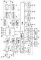
図2は、上記したデジタルテレビジョン放送受信装置11の主要な信号処理系を示している。すなわち、BS/CSデジタル放送受信用のアンテナ43で受信した衛星デジタルテレビジョン放送信号は、入力端子44を介して衛星デジタル放送用のチューナ45に供給されることにより、所望のチャンネルの放送信号が選局される。
FIG. 2 shows a main signal processing system of the digital
そして、このチューナ45で選局された放送信号は、PSK(Phase Shift Keying)復調器46に供給されて、デジタルの映像信号及び音声信号に復調された後、信号処理部47に出力される。
The broadcast signal selected by the
また、地上波放送受信用のアンテナ48で受信した地上デジタルテレビジョン放送信号は、入力端子49を介して地上デジタル放送用のチューナ50に供給されることにより、所望のチャンネルの放送信号が選局される。
The terrestrial digital television broadcast signal received by the terrestrial
そして、このチューナ50で選局された放送信号は、OFDM(Orthogonal Frequency Division Multiplexing)復調器51に供給されて、デジタルの映像信号及び音声信号に復調された後、上記信号処理部47に出力される。
The broadcast signal selected by the
また、上記地上波放送受信用のアンテナ48で受信した地上アナログテレビジョン放送信号は、入力端子49を介して地上アナログ放送用のチューナ52に供給されることにより、所望のチャンネルの放送信号が選局される。そして、このチューナ52で選局された放送信号は、アナログ復調器53に供給されてアナログの映像信号及び音声信号に復調された後、上記信号処理部47に出力される。
The terrestrial analog television broadcast signal received by the terrestrial
ここで、上記信号処理部47は、PSK復調器46及びOFDM復調器51からそれぞれ供給されたデジタルの映像信号及び音声信号に対して、選択的に所定のデジタル信号処理を施し、グラフィック処理部54及び音声処理部55に出力している。
Here, the
また、上記信号処理部47には、複数(図示の場合は4つ)の入力端子56a,56b,56c,56dが接続されている。これら入力端子56a〜56dは、それぞれ、アナログの映像信号及び音声信号を、デジタルテレビジョン放送受信装置11の外部から入力可能とするものである。
The
そして、この信号処理部47は、上記アナログ復調器53及び各入力端子56a〜56dからそれぞれ供給されたアナログの映像信号及び音声信号を選択的にデジタル化し、そのデジタル化された映像信号及び音声信号に対して所定のデジタル信号処理を施した後、グラフィック処理部54及び音声処理部55に出力している。
The
このうち、グラフィック処理部54は、信号処理部47から供給されるデジタルの映像信号に、OSD(On Screen Display)信号生成部57で生成されるOSD信号を重畳して出力する機能を有する。このグラフィック処理部54は、信号処理部47の出力映像信号と、OSD信号生成部57の出力OSD信号とを選択的に出力すること、また、両出力をそれぞれ画面の半分を構成するように組み合わせて出力することができる。
Among these, the
そして、グラフィック処理部54から出力されたデジタルの映像信号は、映像処理部58に供給される。この映像処理部58は、入力されたデジタルの映像信号を、前記映像表示器14で表示可能なフォーマットのアナログ映像信号に変換したり、表示色を任意に調整したりして、映像表示器14に出力して映像表示させるとともに、出力端子59を介して外部に導出させる。この映像処理部58はリモコン17からの指示に応答して、制御部61の制御の基に色調整が可能で、自動色調整モードとユーザが好みによって調整する手動調整モードで動さ可能である。
The digital video signal output from the
また、上記音声処理部55は、入力されたデジタルの音声信号を、前記スピーカ15で再生可能なフォーマットのアナログ音声信号に変換した後、スピーカ15に出力して音声再生させるとともに、出力端子60を介して外部に導出させる。
The
ここで、このデジタルテレビジョン放送受信装置11は、上記した各種の受信動作を含むその全ての動作を制御部61によって統括的に制御されている。この制御部61は、CPU(Central Processing Unit)等を内蔵しており、前記操作部16からの操作情報を受け、または、リモートコントローラ17から送出された操作情報を前記受光部18を介して受信し、その操作内容が反映されるように各部をそれぞれ制御している。
Here, in the digital television
この場合、制御部61は、主として、そのCPUが実行する制御プログラムを格納したROM(Read Only Memory)62と、該CPUに作業エリアを提供するRAM(Random Access Memory)63と、各種の設定情報及び制御情報等が格納される不揮発性メモリ64とを利用している。
In this case, the
また、この制御部61は、カードI/F(Interface)65を介して、前記第1のメモリカード19が装着可能なカードホルダ66に接続されている。これによって、制御部61は、カードホルダ66に装着された第1のメモリカード19と、カードI/F65を介して情報伝送を行なうことができる。
The
さらに、上記制御部61は、カードI/F67を介して、前記第2のメモリカード20が装着可能なカードホルダ68に接続されている。これにより、制御部61は、カードホルダ68に装着された第2のメモリカード20と、カードI/F67を介して情報伝送を行なうことができる。
Further, the
また、上記制御部61は、通信I/F69を介して第1のLAN端子21に接続されている。これにより、制御部61は、第1のLAN端子21に接続されたLAN対応のHDD25と、通信I/F69を介して情報伝送を行なうことができる。この場合、制御部61は、DHCP(Dynamic Host Configuration Protocol)サーバ機能を有し、第1のLAN端子21に接続されたLAN対応のHDD25にIP(Internet Protocol)アドレスを割り当てて制御している。
The
さらに、上記制御部61は、通信I/F70を介して第2のLAN端子22に接続されている。これにより、制御部61は、第2のLAN端子22に接続された各機器(図1参照)と、通信I/F70を介して情報伝送を行なうことができる。
Further, the
また、上記制御部61は、USB I/F71を介して前記USB端子23に接続されている。これにより、制御部61は、USB端子23に接続された各機器(図1参照)と、USB I/F71を介して情報伝送を行なうことができる。
The
さらに、上記制御部61は、i.Link I/F72を介してi.Link端子24に接続されている。これにより、制御部61は、i.Link端子24に接続された各機器(図1参照)と、i.Link I/F72を介して情報伝送を行なうことができる。
Further, the
図3は、上記リモートコントローラ17の外観を示している。このリモートコントローラ17には、主として、電源キー17a、入力切換キー17b、衛星デジタル放送チャンネルのダイレクト選局キー17c、地上波放送チャンネルのダイレクト選局キー17d、クイックキー17e、カーソルキー17f、決定キー17g、番組表キー17h、ページ切換キー17i、faceネット(ナビゲーション)キー17j、戻るキー17k、終了キー17l、青,赤,緑,黄のカラーキー17m、チャンネルアップダウンキー17n、音量調整キー17o、メニューキー17p等が設けられている。
FIG. 3 shows the appearance of the
以上のように、上記受信装置11には、第1及び第2のメモリカード19,20を装着するためのカードホルダ66、68、NAS接続専用の第1のLAN端子21、一般のネットワーク対応映像機器と接続するための第2のLAN端子22の他、各種映像機器を接続するためのUSB(Universal Serial Bus)端子23及びi.Link端子24を備え、いずれも制御部61によって接続状態が管理されている。これらのホルダまたは端子に映像機器を接続する場合には、手動または自動によって「どこ」に「何」が「いつ」接続されているかを示す接続情報が制御部61の不揮発性メモリ64に設定登録される。
As described above, the receiving
ここで、上記したデジタルテレビジョン放送受信装置11の有する予約機能について説明する。この予約機能には、放送予定されている番組を指定して予約を行なう番組指定予約と、チャンネル及び日時を指定して予約を行なう日時指定予約との2種類がある。また、番組指定予約には、指定した番組を指定した録画機器またはメモリカード等の記録媒体に録画する録画予約と、指定した番組の選局のみを行なう視聴予約とがある。さらに、日時指定予約にも、指定したチャンネル及び日時の放送内容を指定した録画機器またはメモリカードの記録媒体に録画する録画予約と、指定したチャンネル及び日時の放送の選局のみを行なう視聴予約とがある。ここでは説明を簡単にするため、番組指定予約の場合について説明するが、日時指定予測の場合も同様の手法で対応することができる。
Here, the reservation function of the digital
図4は、上記デジタルテレビジョン放送受信装置11に対して、番組指定予約を設定する動作を説明するためのフローチャートを示している。この動作は、ユーザがリモートコントローラ17の番組表キー17hを操作することにより、開始(ステップS4a)される。
FIG. 4 shows a flowchart for explaining the operation of setting a program designation reservation for the digital
すると、制御部61は、ステップS4bで、放送信号から予め取得しておいたEPG(Electronic Program Guide)情報に基づいて、図5(a)に示すような電子番組表を映像表示器14に表示させる。
Then, in step S4b, the
これにより、ユーザは、電子番組表の中から所望の番組を選択設定することができる。この選択設定は、リモートコントローラ17のカーソルキー17fを操作して所望の番組を選択し、決定キー17gを操作することにより実行される。
Thereby, the user can select and set a desired program from the electronic program guide. This selection setting is executed by operating the cursor key 17f of the
このため、制御部61は、ステップS4cで、電子番組表の中から所望の番組が選択設定されたことを検知すると、ステップS4dで、図5(b)に示すような予約選択画面を表示させる。
Therefore, when the
この予約選択画面では、先に選択設定した番組に対する放送チャンネル、放送日、内容の概略説明等が表示され、録画予約か視聴予約かをユーザに選択させることができる。この選択も、リモートコントローラ17のカーソルキー17fを操作して録画予約か視聴予約かを選択し、決定キー17gを操作することにより実行される。
On this reservation selection screen, a broadcast channel, a broadcast date, a general description of the contents, etc. for the previously selected program are displayed, and the user can select whether to make a recording reservation or a viewing reservation. This selection is also executed by operating the cursor key 17f of the
そして、制御部61は、ステップS4eで、録画予約及び視聴予約のいずれが選択されたかを判別し、視聴予約が選択されたと判断された場合、ステップS4fで、視聴予約のために設定された各情報を不揮発性メモリ64に格納して視聴予約設定を完了し、処理を終了(ステップS4i)する。このように視聴予約が設定されることにより、選択された番組が自動的に選局され視聴に供されるようになる。
Then, the
また、上記ステップS4eで録画予約が選択されたと判断された場合、制御部61は、ステップS4gで、図5(c)に示すような録画予約設定画面を表示させる。この録画予約設定画面では、先に選択設定した番組を録画予約するか否かの選択、録画するデジタル録画機器または記録媒体の指定等を行なうことができる。
If it is determined in step S4e that the recording reservation has been selected, the
そして、制御部61は、録画予約設定画面において録画予約が要求され種々の必要項目が設定された場合に、ステップS4hで、録画予約のために設定された各情報を不揮発性メモリ64に格納して録画予約設定を完了し、処理を終了(ステップS4i)する。このように録画予約が設定されることにより、選択された番組が、指定されたデジタル録画機器または記録媒体に自動的に録画されるようになる。
Then, when the recording reservation is requested and various necessary items are set on the recording reservation setting screen, the
上記構成によるデジタル放送受信装置において、以下、図6に示すフローチャートを参照して本発明の特徴とする記録先制御手順について説明する。ここでは、例として、第1のLAN端子(ここではコンテンツ伝送専用ネットワーク接続とする)21に接続されるハイビジョン画質の映像信号を記録可能なLAN対応HDD25と第2のLAN端子(ここでは上記専用ネットワーク接続に対して汎用ネットワーク接続とする)22にハブ26を介して接続されるLAN対応HDD27とがいずれも記録可能な状態にあり、通常は汎用ネットワーク側のHDD27を選択して記録し、ハイビジョン画質の映像信号は専用ネットワーク側のHDD25を選択して記録するモードに設定してあるものとする。
In the digital broadcast receiving apparatus having the above configuration, a recording destination control procedure that is a feature of the present invention will be described below with reference to a flowchart shown in FIG. Here, as an example, a LAN-
LAN接続機器の機能については、接続設定時に、機器識別情報、記録位置(パス)情報と共に、図2に示した制御部61の不揮発性メモリ64に登録される。これにより、上記LAN対応HDD25,27が第1の端子21、第2の端子22のどちらに接続されているか、受信装置側で認識される。
The function of the LAN connection device is registered in the
上記の事前設定後、記録コンテンツが入力されたことを判別すると(ステップS6a)、ビットレートは閾値以上か判断する(ステップS6b)。この閾値は、ハイビジョン画質の映像信号の転送レートに対応させておく。これにより、ハイビジョン画質の映像コンテンツが入力された場合には、ビットレートが閾値以上となるため、専用LAN側のHDD25で記録を開始する(ステップS6c)。ビットレートが閾値に満たない場合には、汎用LAN側のHDD27で記録を開始する(ステップS6d)。
When it is determined that the recorded content has been input after the above presetting (step S6a), it is determined whether the bit rate is equal to or higher than the threshold (step S6b). This threshold value is made to correspond to the transfer rate of a high-definition video signal. As a result, when video content with high-definition image quality is input, the bit rate is equal to or greater than the threshold value, so recording starts on the
ここで、上記ステップS6dで、汎用LAN側のHDD27への記録が開始された場合、ステップS6eにて記録終了を監視し、記録が継続している場合には、ステップS6fでQoS(回線サービス品質)が低下して閾値以下になっているか監視し、ステップS6gで記録中のHDD27の記憶領域の残量を監視する。記録中にQosが閾値以下となる、または記憶領域の残量がなくなるといった状況になった場合には、回線品質が確保されている専用LAN側のHDD25に記録先を自動的に切り替え、記録が途絶えないようにする(ステップS6c)。ステップS6eで記録が終了した場合には、ステップS6aに戻って、次の記録コンテンツの入力待ちとする。
Here, when the recording to the
上記ステップS6cで専用LAN側HDD25の記録が開始された場合には、ステップS6hで記録終了を監視する。記録が継続している場合には、当該HDD25に外部からのアクセスがあるか監視し(ステップs6i)、外部アクセスがあった場合には、記録中を理由にアクセス不許可とする(ステップS6j)。ステップS6hでHDD25の記録終了が検出された後に、当該HDD25に外部からアクセスがあった場合にはこれを検知して(ステップS6k)、アクセス許可を通知する(ステップS6l)。その後、ステップS6aに戻り、次の記録コンテンツの入力待ちとなる。
When the recording of the dedicated
ここで、上記のように専用ネットワーク対応の第1の端子21と汎用ネットワーク対応の第2の端子22を区別している場合、それぞれのLAN接続機器の設定登録時、記録先指定時などでユーザに両端子の役割が判断可能なように、各端子の表示を区別しておくことが望ましい。図7に機器選択のメニュー表示例を示す。ここでは、第1の端子21に接続されるネットワークを「LAN1」とし、HDDマークに「Common」を表記する。一方、第2の端子22に接続されるネットワークを「LAN2」とし、HDDマークに「Common Folder」を表記する。これにより、ユーザは機器選択時に専用ネットワーク側のHDDと汎用ネットワーク側のHDDを誤認しないようにすることができる。
Here, when the
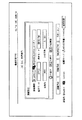
また、図8に番組指定予約の設定入力画面の表示例を示す。この例では、録画設定メニューの記録機器の選択をLAN2の接続機器を指定しているが、表示画面の下部に示されているように、録画先はLAN1のHDDに優先して自動録画されることになる。 FIG. 8 shows a display example of a setting input screen for program designation reservation. In this example, the LAN2 connected device is specified for selecting the recording device in the recording setting menu, but as shown in the lower part of the display screen, the recording destination is automatically recorded in preference to the LAN1 HDD. It will be.
したがって、上記構成によるデジタルテレビジョン放送受信装置では、コンテンツ記録専用のネットワークと一般通信にも利用する汎用ネットワークとを区別してそれぞれのLAN端子を設け、ハイビジョン画質の映像信号の記録用に専用ネットワーク側の記録機器を自動的に選択するようにしているので、ネットワーク環境が原因で記録できなかったハイビジョン画質の映像信号を記録することができるようになる。ここで、専用ネットワーク側のLAN端子に、接続したLAN対応HDDの自動登録機能を備えるようにすれば、LANケーブルを用いてそのHDDを接続しただけで、記録先として自動的に記録パスを登録することも可能である。 Therefore, in the digital television broadcast receiving apparatus having the above-described configuration, a LAN dedicated to content recording and a general-purpose network used for general communication are distinguished from each other, and each LAN terminal is provided to record a high-definition image quality video signal. Since the recording device is automatically selected, a high-definition video signal that cannot be recorded due to the network environment can be recorded. Here, if the LAN terminal on the dedicated network side is provided with an automatic registration function for the connected LAN-compatible HDD, the recording path is automatically registered as a recording destination just by connecting the HDD using a LAN cable. It is also possible to do.
また、コンテンツを記録する際に、ハイビジョンあるいはビットレートが高いコンテンツを自動的に判断して、専用ネットワーク側の端子に接続されたHDDに記録するように設定できるので、ビットレートが高いコンテンツも、汎用ネットワークの障害を回避して専用ネットワーク側のHDDに記録先を変更することが可能となる。 In addition, when recording content, it can be set to automatically determine content with a high-definition or high bit rate and record it on the HDD connected to the terminal on the dedicated network side, so content with a high bit rate It is possible to avoid the failure of the general-purpose network and change the recording destination to the HDD on the dedicated network side.
また、汎用ネットワーク側に接続されたHDDに記録している際に、記録しているコンテンツのQOSが低下して記録不能となった場合にも、これを自動的に検知して専用ネットワーク側のHDDに記録先を変更する機能を有している。この機能を備えることで、汎用ネットワーク側のHDDへの記録速度が低下し、最悪記録ができなくなっても、専用ネットワーク側のHDDに記録先を変更することができる。 Also, when recording on the HDD connected to the general-purpose network side, even if the QOS of the recorded content decreases and recording becomes impossible, this is automatically detected and the dedicated network side The HDD has a function of changing the recording destination. With this function, even if the recording speed to the HDD on the general-purpose network side decreases and the worst recording cannot be performed, the recording destination can be changed to the HDD on the dedicated network side.
また、汎用ネットワーク側に接続されたHDDに記録している際に、そのHDDの記録要領がなくなった場合でも、これを自動的に検知して専用ネットワーク側のHDDに記録先を変更する機能を有している。この機能を備えることで、汎用ネットワーク側のHDDで残量以上のコンテンツを記録するような状態となっても、記録容量がなくなった時点で専用ネットワーク側のHDDに記録先を変更することができる。 In addition, when recording to an HDD connected to the general-purpose network side, even if the recording procedure for that HDD is lost, this function automatically detects this and changes the recording destination to the HDD on the dedicated network side. Have. By having this function, even if the HDD on the general-purpose network side records more content than the remaining amount, the recording destination can be changed to the HDD on the dedicated network side when the recording capacity is exhausted. .
さらに、専用ネットワーク側HDDの記録中でQOSを低下させないために、ゲートウェイ機能を持たせている。これにより、専用ネットワーク側のHDDに記録している最中に外部から当該HDDのアクセス要求があっても、これを制限してQOS低下を防ぎ、記録を行っていないときのみアクセス要求を受け付けられるようになり、専用ネットワーク側のHDDの有効利用を図ることができる。 In addition, a gateway function is provided so as not to lower the QOS during recording on the dedicated network side HDD. As a result, even if there is an access request for the HDD from the outside during recording in the HDD on the dedicated network side, this is limited to prevent the QOS from being lowered, and the access request can be accepted only when recording is not performed. Thus, the HDD on the dedicated network side can be effectively used.
以上、この発明は上記した実施の形態そのままに限定されるものではなく、実施段階ではその要旨を逸脱しない範囲で構成要素を種々変形して具体化することができる。また、上記した実施の形態に開示されている複数の構成要素を適宜に組み合わせることにより、種々の発明を形成することができる。例えば、実施の形態に示される全構成要素から幾つかの構成要素を削除しても良いものである。さらに、異なる実施の形態に係る構成要素を適宜組み合わせても良いものである。 As described above, the present invention is not limited to the above-described embodiments as they are, and various modifications can be made to the constituent elements without departing from the spirit of the invention at the implementation stage. Various inventions can be formed by appropriately combining a plurality of constituent elements disclosed in the above-described embodiments. For example, some components may be deleted from all the components shown in the embodiment. Furthermore, constituent elements according to different embodiments may be appropriately combined.
11…デジタルテレビジョン放送受信装置、12…キャビネット、13…支持台、14…映像表示器、15…スピーカ、16…操作部、17…リモートコントローラ、18…受光部、43…アンテナ、44…入力端子、45…チューナ、46…PSK復調器、47…信号処理部、48…アンテナ、49…入力端子、50…チューナ、51…OFDM復調器、52…チューナ、53…アナログ復調器、54…グラフィック処理部、55…音声処理部、56a〜56d…入力端子、57…OSD信号生成部、58…映像処理部、59…出力端子、60…出力端子、61…制御部、62…ROM、63…RAM、64…不揮発性メモリ、65…カードI/F(Interface)、66…カードホルダ、67…カードI/F、68…カードホルダ、69…通信I/F、70…通信I/F、71…USB I/F、72…i.Link I/F。
DESCRIPTION OF
Claims (7)
一般データ通信に用いる汎用ネットワークに接続される第2の端子と、
前記第1、第2の端子それぞれに接続される記録再生装置を認識する装置認識手段と、
コンテンツ記録時に当該コンテンツの伝送モード、伝送レート、前記汎用ネットワークの回線品質の少なくともいずれかを自動的に認識する状態認識手段と、
前記状態認識手段の認識結果に基づいて前記コンテンツの記録先を前記第1の端子と第2の端子のいずれか一方に接続される記録再生装置に自動的に決定する記録先選択手段とを具備することを特徴とする情報処理装置。 A first terminal connected to a dedicated network mainly dedicated to content recording and playback;
A second terminal connected to a general-purpose network used for general data communication;
Device recognition means for recognizing a recording / reproducing device connected to each of the first and second terminals;
State recognition means for automatically recognizing at least one of the transmission mode, transmission rate, and line quality of the general-purpose network when recording the content;
Recording destination selection means for automatically determining the recording destination of the content as a recording / reproducing apparatus connected to one of the first terminal and the second terminal based on the recognition result of the state recognition means; An information processing apparatus characterized by:
前記記録先選択手段は、前記コンテンツの記録先を前記第1の端子に接続される専用ネットワーク上の記録再生装置とすることを特徴とする請求項1記載の情報処理装置。 When the state recognition means recognizes that the transmission mode of the content is high-quality information or the transmission rate reaches a specified bit rate,
The information processing apparatus according to claim 1, wherein the recording destination selecting unit is a recording / reproducing apparatus on a dedicated network connected to the first terminal as a recording destination of the content.
前記記録先選択手段は、前記汎用ネットワークに接続される記録再生装置へのコンテンツ伝送を前記専用ネットワークに接続される記録再生装置へのコンテンツ伝送に切り替えることを特徴とする請求項1記載の情報処理装置。 When the state recognition means recognizes that the line quality of the general-purpose network does not satisfy a specified value,
2. The information processing according to claim 1, wherein the recording destination selection unit switches content transmission to a recording / reproducing apparatus connected to the general-purpose network to content transmission to a recording / reproducing apparatus connected to the dedicated network. apparatus.
前記記録先選択手段は、前記汎用ネットワークに接続される記録再生装置へのコンテンツ伝送を前記専用ネットワークに接続される記録再生装置へのコンテンツ伝送に切り替えることを特徴とする請求項1記載の情報処理装置。 When the state recognition unit recognizes that the remaining recording capacity of the recording / playback apparatus connected to the general-purpose network is less than a specified value,
2. The information processing according to claim 1, wherein the recording destination selection unit switches content transmission to a recording / reproducing apparatus connected to the general-purpose network to content transmission to a recording / reproducing apparatus connected to the dedicated network. apparatus.
前記第1、第2の端子それぞれに接続される記録再生装置を認識する装置認識過程と、
コンテンツ記録時に当該コンテンツの伝送モード、伝送レート、前記汎用ネットワークの回線品質の少なくともいずれかを自動的に認識する状態認識過程と、
前記状態認識過程の認識結果に基づいて前記コンテンツの記録先を前記第1の端子と第2の端子のいずれか一方に接続される記録再生装置に自動的に決定する記録先選択過程とを具備することを特徴とする情報処理装置の記録先制御方法。 It is mainly used in an information processing apparatus including a first terminal connected to a dedicated network dedicated to content recording / playback and a second terminal connected to a general-purpose network used for general data communication.
A device recognition process for recognizing a recording / reproducing device connected to each of the first and second terminals;
A state recognition process for automatically recognizing at least one of the transmission mode, transmission rate, and line quality of the general-purpose network when recording the content;
A recording destination selection step of automatically determining a recording destination of the content to a recording / reproducing device connected to one of the first terminal and the second terminal based on the recognition result of the state recognition step. A recording destination control method for an information processing apparatus.
Priority Applications (1)
| Application Number | Priority Date | Filing Date | Title |
|---|---|---|---|
| JP2004280698A JP4387911B2 (en) | 2004-09-27 | 2004-09-27 | Information processing apparatus and recording destination control method thereof |
Applications Claiming Priority (1)
| Application Number | Priority Date | Filing Date | Title |
|---|---|---|---|
| JP2004280698A JP4387911B2 (en) | 2004-09-27 | 2004-09-27 | Information processing apparatus and recording destination control method thereof |
Publications (3)
| Publication Number | Publication Date |
|---|---|
| JP2006094438A JP2006094438A (en) | 2006-04-06 |
| JP2006094438A5 JP2006094438A5 (en) | 2006-11-24 |
| JP4387911B2 true JP4387911B2 (en) | 2009-12-24 |
Family
ID=36234928
Family Applications (1)
| Application Number | Title | Priority Date | Filing Date |
|---|---|---|---|
| JP2004280698A Expired - Fee Related JP4387911B2 (en) | 2004-09-27 | 2004-09-27 | Information processing apparatus and recording destination control method thereof |
Country Status (1)
| Country | Link |
|---|---|
| JP (1) | JP4387911B2 (en) |
Families Citing this family (4)
| Publication number | Priority date | Publication date | Assignee | Title |
|---|---|---|---|---|
| JP4143083B2 (en) | 2005-08-31 | 2008-09-03 | 株式会社東芝 | Broadcast receiving apparatus and control method thereof |
| KR100805238B1 (en) | 2006-09-11 | 2008-02-21 | 삼성전자주식회사 | Digital broadcast receiving apparatus |
| JP4902420B2 (en) * | 2007-05-02 | 2012-03-21 | 株式会社アイ・オー・データ機器 | Television program recording method, television program recording system, and external storage control device |
| JP2011013860A (en) * | 2009-06-30 | 2011-01-20 | Toshiba Corp | Display-processing device, display-processing method, and program |
-
2004
- 2004-09-27 JP JP2004280698A patent/JP4387911B2/en not_active Expired - Fee Related
Also Published As
| Publication number | Publication date |
|---|---|
| JP2006094438A (en) | 2006-04-06 |
Similar Documents
| Publication | Publication Date | Title |
|---|---|---|
| JP4427490B2 (en) | Video display processing apparatus and information processing method for video recording | |
| JP2008251086A (en) | Disk recorder management device and disk recorder management method | |
| CN100473127C (en) | Information processing apparatus, method of controlling its external appliances and a television broadcast receiver | |
| JP4387911B2 (en) | Information processing apparatus and recording destination control method thereof | |
| US20060227686A1 (en) | Recording information management apparatus and recording information management method | |
| US7751772B2 (en) | Broadcast receiver and method of control thereof | |
| JP2008278101A (en) | Video recording control device and video recording control method | |
| JP2006245682A (en) | Apparatus and method for recording program | |
| JP2006094408A (en) | Broadcast receiver | |
| EP1641258A1 (en) | Video recording control device and video recording control method | |
| JP4190526B2 (en) | Information processing device | |
| JP2008152707A (en) | Address information control device and address information control method | |
| JP4585370B2 (en) | Broadcast receiving apparatus and broadcast receiving method | |
| JP4538068B2 (en) | Content reproduction apparatus and content reproduction method | |
| JP2008028659A (en) | Communication apparatus and communication method | |
| US20070028289A1 (en) | Picture signal processor and picture signal processing method | |
| JP2006072815A (en) | Signal processor and its control method | |
| JP2008141349A (en) | Network apparatus and control method of network apparatus | |
| JP4602449B2 (en) | Content processing apparatus and content processing method | |
| JP2006094433A (en) | Broadcasting receiver and broadcast reception method | |
| JP4557656B2 (en) | Broadcast content processing apparatus and control method of broadcast content processing apparatus | |
| JP4825627B2 (en) | Broadcast receiving apparatus and method | |
| JP5132472B2 (en) | Recording control apparatus and recording control method | |
| JP2007336571A (en) | Apparatus and method for controlling video recording | |
| JP2007013563A (en) | Program data moving apparatus and method |
Legal Events
| Date | Code | Title | Description |
|---|---|---|---|
| A521 | Written amendment |
Free format text: JAPANESE INTERMEDIATE CODE: A523 Effective date: 20061005 |
|
| A621 | Written request for application examination |
Free format text: JAPANESE INTERMEDIATE CODE: A621 Effective date: 20061005 |
|
| TRDD | Decision of grant or rejection written | ||
| A01 | Written decision to grant a patent or to grant a registration (utility model) |
Free format text: JAPANESE INTERMEDIATE CODE: A01 Effective date: 20090908 |
|
| A01 | Written decision to grant a patent or to grant a registration (utility model) |
Free format text: JAPANESE INTERMEDIATE CODE: A01 |
|
| A61 | First payment of annual fees (during grant procedure) |
Free format text: JAPANESE INTERMEDIATE CODE: A61 Effective date: 20091001 |
|
| FPAY | Renewal fee payment (event date is renewal date of database) |
Free format text: PAYMENT UNTIL: 20121009 Year of fee payment: 3 |
|
| FPAY | Renewal fee payment (event date is renewal date of database) |
Free format text: PAYMENT UNTIL: 20131009 Year of fee payment: 4 |
|
| LAPS | Cancellation because of no payment of annual fees |