JP4386295B2 - Humidity sensor - Google Patents
Humidity sensor Download PDFInfo
- Publication number
- JP4386295B2 JP4386295B2 JP2007112136A JP2007112136A JP4386295B2 JP 4386295 B2 JP4386295 B2 JP 4386295B2 JP 2007112136 A JP2007112136 A JP 2007112136A JP 2007112136 A JP2007112136 A JP 2007112136A JP 4386295 B2 JP4386295 B2 JP 4386295B2
- Authority
- JP
- Japan
- Prior art keywords
- relative humidity
- humidity
- moisture
- atmosphere
- humidity sensor
- Prior art date
- Legal status (The legal status is an assumption and is not a legal conclusion. Google has not performed a legal analysis and makes no representation as to the accuracy of the status listed.)
- Expired - Fee Related
Links
Images


Classifications
-
- G—PHYSICS
- G01—MEASURING; TESTING
- G01N—INVESTIGATING OR ANALYSING MATERIALS BY DETERMINING THEIR CHEMICAL OR PHYSICAL PROPERTIES
- G01N27/00—Investigating or analysing materials by the use of electric, electrochemical, or magnetic means
- G01N27/02—Investigating or analysing materials by the use of electric, electrochemical, or magnetic means by investigating impedance
- G01N27/22—Investigating or analysing materials by the use of electric, electrochemical, or magnetic means by investigating impedance by investigating capacitance
- G01N27/223—Investigating or analysing materials by the use of electric, electrochemical, or magnetic means by investigating impedance by investigating capacitance for determining moisture content, e.g. humidity
- G01N27/225—Investigating or analysing materials by the use of electric, electrochemical, or magnetic means by investigating impedance by investigating capacitance for determining moisture content, e.g. humidity by using hygroscopic materials
Description
本発明は、当該湿度センサを取り巻く雰囲気の湿度を検出する湿度センサに関する。 The present invention relates to a humidity sensor that detects the humidity of the atmosphere surrounding the humidity sensor.
この種の湿度センサとしては、従来、例えば特許文献1に記載の技術が知られている。この技術では、半導体基板と、この半導体基板上に形成されたシリコン酸化膜と、シリコン酸化膜上に同一平面上にて離間して対向するように形成された2個の電極と、これら2個の電極を覆うように形成されたシリコン窒化膜と、シリコン窒化膜上に両電極及びこれら両電極の間を覆うように形成され、湿度に応じて誘電率が変化する感湿膜とを備えている。このように構成されることで、当該センサを取り巻く雰囲気の湿度の変化に応じて変化する、2個の電極間の容量値に基づき、雰囲気の湿度の変化を検出することができるようになる。
ところで、こうした従来の湿度センサでは、感湿膜を形成する材料として、一般に、例えばポリイミドや酪酸酢酸セルロース等の吸湿性高分子有機材料が採用されている。そして、そのような高分子有機材料にて形成された感湿膜を備える湿度センサは、次のような課題を有している。 By the way, in such a conventional humidity sensor, a hygroscopic polymer organic material such as polyimide or cellulose butyrate acetate is generally employed as a material for forming the moisture sensitive film. And the humidity sensor provided with the moisture sensitive film | membrane formed with such a polymeric organic material has the following subjects.
詳しくは、感湿膜を形成する高分子有機材料は、微視的には、鎖状に長く連なった無数の分子群が互いに密に絡み合った状態にある。そうした感湿膜を有する湿度センサが高湿な雰囲気中に長期間に渡って置かれると、雰囲気に含まれる水分子に起因して、密に絡み合っていた分子群は徐々にほぐれる。そして、ほぐれた分子群を有する感湿膜は、密に絡み合った分子群を有する感湿膜に比べて、同一の湿度下であっても、雰囲気に含まれる水分子をより多く内部に取り込むようになる(いわゆる膨潤現象)。そして、より多くの水分子を内部に取り込むと、図14に示すように、同一の相対湿度下であっても、センサ出力値が増大してしまい、ひいては、こうした湿度センサのセンサ出力値の変動は、雰囲気の相対湿度の検出精度を低下させてしまう。なお、図14においては、長期間に渡って使用された湿度センサのセンサ出力値と雰囲気の相対湿度との関係を直線Aとして、ほとんど使用されていない湿度センサのセンサ出力値と雰囲気の相対湿度との関係を直線Bとして、それぞれ示している。 Specifically, the macromolecular organic material forming the moisture-sensitive film is microscopically in a state where innumerable molecular groups that are long and chain-like are intertwined closely with each other. When a humidity sensor having such a moisture sensitive film is placed in a humid atmosphere for a long period of time, molecular groups that have been intertwined gradually are loosened due to water molecules contained in the atmosphere. And, a moisture-sensitive film having loose molecular groups is more likely to take in water molecules contained in the atmosphere even under the same humidity as compared to a moisture-sensitive film having closely entangled molecular groups. (So-called swelling phenomenon). When more water molecules are taken into the sensor, the sensor output value increases even under the same relative humidity as shown in FIG. 14, and as a result, the sensor output value fluctuates in such a humidity sensor. Reduces the detection accuracy of the relative humidity of the atmosphere. In FIG. 14, the relationship between the sensor output value of the humidity sensor that has been used for a long period of time and the relative humidity of the atmosphere is a straight line A, and the sensor output value of the humidity sensor that is rarely used and the relative humidity of the atmosphere. Are shown as straight lines B, respectively.
本発明は、こうした実情に鑑みてなされたものであって、その目的は、当初の検出精度を長期間に渡って維持することのできる湿度センサを提供することにある。 The present invention has been made in view of such circumstances, and an object of the present invention is to provide a humidity sensor that can maintain the initial detection accuracy over a long period of time.
こうした目的を達成するため、請求項1に記載の発明では、水分を吸着することによって物理量が変化する感湿部材と、その物理量の変化を検出するための検出部材とを有する湿度センサ素子と、前記検出部材の出力信号を処理する処理回路とを備え、雰囲気の湿度変化を前記物理量の変化として検出する湿度センサとして、前記感湿部材は、水分を吸着するための多数の細孔を有する無機材料から形成されていることとした。
In order to achieve such an object, in the invention according to
湿度センサとしてのこのような構成では、まず、多数の細孔を有する無機材料から形成された感湿部材が、雰囲気に含まれる水分を吸着し、感湿部材の物理量を変化させる。すなわち、雰囲気の相対湿度が高ければ、感湿部材はより多くの水分を吸着するとともに、雰囲気の相対湿度が低ければ、感湿部材はそれほど多くの水分を吸着しない。このようにして、感湿部材は、雰囲気の水分に応じて物理量を変化させる。また、検出部材によって、そうした物理量の変化を検出し、出力信号を処理回路に出力する。そして、処理回路において、検出部材から出力された出力信号が処理されるようになる。 In such a configuration as a humidity sensor, first, a moisture-sensitive member formed of an inorganic material having a large number of pores adsorbs moisture contained in the atmosphere and changes the physical quantity of the moisture-sensitive member. That is, when the relative humidity of the atmosphere is high, the moisture sensitive member adsorbs more moisture, and when the relative humidity of the atmosphere is low, the moisture sensitive member does not adsorb much moisture. In this way, the moisture sensitive member changes the physical quantity according to the moisture in the atmosphere. Further, the change in the physical quantity is detected by the detection member, and an output signal is output to the processing circuit. Then, in the processing circuit, the output signal output from the detection member is processed.
ここで、感湿部材は無機材料から形成されている。無機材料にあっては、一般に、高分子有機材料のような、いわゆる膨潤現象が生じない。すなわち、無機材料は、有機材料と比較して、その物性が安定しており、長期間に渡って変化しない。したがって、そうした無機材料から形成されている感湿部材を用いれば、たとえ長期間経過した場合であっても、同一の相対湿度下において、同一のセンサ出力値を維持し、変動することはほとんどないため、雰囲気の相対湿度について、当初の検出精度を長期間に渡って維持することができるようになる。 Here, the moisture sensitive member is formed of an inorganic material. In general, so-called swelling phenomenon does not occur in an inorganic material unlike a polymer organic material. That is, the inorganic material has stable physical properties as compared with the organic material and does not change over a long period of time. Therefore, if a moisture-sensitive member made of such an inorganic material is used, the same sensor output value is maintained and hardly fluctuated under the same relative humidity even when a long time has passed. Therefore, the initial detection accuracy can be maintained over a long period of time with respect to the relative humidity of the atmosphere.
こうした請求項1に記載の構成では、前記感湿部材は、水分を吸着することによってその誘電率が変化する感湿膜とし、前記検出部材は、前記感湿膜の容量値の変化を検出するための一対の電極とし、当該湿度センサは、前記感湿膜の誘電率の変化に基づいて相対湿度を検出する容量式の湿度センサとすることができる。
In the configuration according to
湿度センサとしてのこのような構成では、まず、多数の細孔を有する無機材料から形成された感湿膜が、雰囲気に含まれる水分を吸着し、感湿膜の誘電率を変化させる。すなわち、雰囲気の相対湿度が高ければ、感湿膜はより多くの水分を吸着するため、誘電率が高くなる。一方、雰囲気の相対湿度が低ければ、感湿膜はそれほど多くの水分を吸着しないため、感湿膜の誘電率は低くなる。このようにして、感湿膜は、雰囲気の水分に応じて誘電率を変化させる。また、一対の電極は、感湿膜の誘電率、換言すれば、これら一対の電極間の容量値の変化を検出し、出力信号を処理回路に出力する。そして、処理回路において、検出部材から出力された出力信号が処理されるようになる。なお、こうした容量式の湿度センサの構造自体は一般的に知られているものであり、そうした一般的に使用される技術を用いることで、検出精度を長期間に渡って維持することのできる湿度センサを容易に構成することができるようになる。 In such a configuration as a humidity sensor, first, a moisture sensitive film formed of an inorganic material having a large number of pores adsorbs moisture contained in the atmosphere, and changes the dielectric constant of the moisture sensitive film. That is, if the relative humidity of the atmosphere is high, the moisture sensitive film adsorbs more moisture, so that the dielectric constant becomes high. On the other hand, when the relative humidity of the atmosphere is low, the moisture sensitive film does not adsorb so much moisture, so that the dielectric constant of the moisture sensitive film becomes low. In this way, the moisture sensitive film changes the dielectric constant according to the moisture in the atmosphere. The pair of electrodes detects a change in the dielectric constant of the moisture sensitive film, in other words, a capacitance value between the pair of electrodes, and outputs an output signal to the processing circuit. Then, in the processing circuit, the output signal output from the detection member is processed. In addition, the structure itself of such a capacitive humidity sensor is generally known, and by using such a commonly used technology, the humidity at which detection accuracy can be maintained over a long period of time. The sensor can be easily configured.
ところで、所定相対湿度に満たない雰囲気下では、感湿膜の細孔内部まで浸入する水分子は少ないものの、所定相対湿度を超える雰囲気下では、感湿膜の細孔内部まで浸入する水分子が急増する現象である、いわゆる毛管凝集現象が知られている。なお、感湿膜の細孔内部まで水分子が浸入することは、感湿膜に吸着される水分子、すなわち、誘電率や容量値が急増することを意味する。そして、この毛管凝集現象が生じる所定相対湿度は細孔径(直径)に大きく関係することが、発明者らによって確認されている。 By the way, in an atmosphere that does not reach the predetermined relative humidity, there are few water molecules that penetrate into the pores of the moisture sensitive film, but in an atmosphere that exceeds the predetermined relative humidity, there are water molecules that penetrate into the pores of the moisture sensitive film. A so-called capillary aggregation phenomenon, which is a rapidly increasing phenomenon, is known. In addition, the penetration of water molecules into the pores of the moisture-sensitive film means that the water molecules adsorbed on the moisture-sensitive film, that is, the dielectric constant and the capacitance value rapidly increase. The inventors have confirmed that the predetermined relative humidity at which this capillary aggregation phenomenon occurs is largely related to the pore diameter (diameter).
その点、請求項1に記載の発明のように、前記細孔の直径は、雰囲気に含まれる水分子が急激に細孔の内部に浸入する現象である毛管凝集現象が所定相対湿度において生じる直径に設定されていることとした。
In that respect , as in the invention described in
これにより、所望の相対湿度で毛管凝集現象を生じさせることができるようになる。具体的には、前記所定相対湿度よりも高い相対湿度の雰囲気における、湿度変化に対する容量値の変化率は、前記所定相対湿度よりも低い相対湿度の雰囲気における、湿度変化に対する容量値の変化率よりも大きくなる。ここで、湿度変化に対する容量値の変化率とは、相対湿度の変化に対する当該湿度センサの感度に相当し、相対湿度の変化に対する当該湿度センサの検出精度に影響する。そのため、上記構成によれば、例えば、所定相対湿度よりも高い相対湿度の雰囲気における検出精度を、所定相対湿度よりも低い相対湿度の雰囲気における検出精度より高めることができるようになる。 As a result, the capillary aggregation phenomenon can be caused at a desired relative humidity. Specifically, the change rate of the capacity value with respect to the humidity change in the atmosphere with the relative humidity higher than the predetermined relative humidity is higher than the change rate of the capacity value with respect to the humidity change in the atmosphere with the relative humidity lower than the predetermined relative humidity. Also grows. Here, the change rate of the capacitance value with respect to the humidity change corresponds to the sensitivity of the humidity sensor with respect to the change of the relative humidity, and affects the detection accuracy of the humidity sensor with respect to the change of the relative humidity. Therefore, according to the above configuration, for example, the detection accuracy in an atmosphere having a relative humidity higher than the predetermined relative humidity can be improved from the detection accuracy in an atmosphere having a relative humidity lower than the predetermined relative humidity.
また、従来の高分子有機物からなる感湿膜を有する湿度センサでは、相対湿度がおよそ「5%〜90%」の雰囲気において一律の検出精度をもって相対湿度を検出することはできるものの、相対湿度がおよそ「95%」よりも高い雰囲気においては、湿度変化に対する容量値の変化率が変化してしまうため、高い検出精度をもって相対湿度を検出することは難しかった。 In addition, in a humidity sensor having a conventional moisture sensitive film made of a polymer organic material, although relative humidity can be detected with uniform detection accuracy in an atmosphere where the relative humidity is approximately “5% to 90%”, the relative humidity is In an atmosphere higher than about “95%”, the rate of change of the capacitance value with respect to the humidity change changes, and it is difficult to detect the relative humidity with high detection accuracy.
その点、請求項1に記載の発明のように、前記細孔の直径を「10〜50nm」に設定すれば、相対湿度がおよそ「95%」よりも高い雰囲気における検出精度を、相対湿度がおよそ「95%」よりも低い雰囲気における検出精度よりも高めることができるようになる。特に、請求項1に記載の発明のように、前記細孔の直径の分布を、直径を中心として±1nm以内に設定することが望ましい。 In that respect , if the diameter of the pore is set to “10 to 50 nm” as in the first aspect of the invention, the detection accuracy in an atmosphere where the relative humidity is higher than about “95%” is obtained. The detection accuracy in an atmosphere lower than about “95%” can be improved. In particular , as in the first aspect of the invention, it is desirable to set the distribution of the diameters of the pores within ± 1 nm with the diameter as the center.
なお、こうした構成において、例えば請求項2に記載の発明のように、前記一対の電極は、前記感湿膜に覆われているとともに、櫛歯形状に形成されていることとしてもよい。あるいは、例えば請求項3に記載の発明のように、前記一対の電極は、前記感湿膜を上下から挟むように配置されるとともに、平板形状に形成されていることとしてもよい。
In such a configuration, as in the invention described in
また、上記請求項1〜3のいずれかに記載の構成において、例えば請求項4に記載の発明のように、一対の電極を有するとともに相対湿度によってその容量値が変化しない第2容量素子をさらに備え、前記処理回路は、この第2容量素子の一対の電極と前記湿度センサ素子を構成する一対の電極との容量差を電圧に変換するCV変換回路を含み、前記CV変換回路の出力電圧値であるCV変換値に基づいて雰囲気の相対湿度を検出することとすれば、たとえ上記容量差が微小であっても、雰囲気の相対湿度を精度良く検出することができるようになる。
Further, in the configuration according to any one of
また、上記請求項1〜3のいずれかに記載の構成において、例えば請求項5に記載の発明では、水分を吸着することによってその誘電率が変化する高分子有機物からなる感湿膜と、該感湿膜に覆われた一対の電極とを有する第3容量素子をさらに備え、前記処理回路は、この第3容量素子の一対の電極と前記湿度センサ素子を構成する一対の電極との容量差を電圧に変換するCV変換回路を含み、前記CV変換回路の出力電圧値であるCV変換値に基づいて雰囲気の相対湿度を検出することとしてもよい。
Further, in the structure according to any one of
こうした構成では、第3容量素子の容量値は相対湿度に対してほぼ直線状に変化するものの、湿度センサ素子の容量値は、相対湿度範囲によっては、第3容量素子よりもより急峻な直線状に変化したり、逆にほとんど変化しなかったりする。そのため、湿度センサ素子の容量値がほとんど変化しない相対湿度範囲においては、湿度センサ素子と第3容量素子との容量差を大きくすることができるため、従来の湿度センサと同程度の精度をもって、雰囲気の相対湿度を検出することができる。一方、湿度センサ素子の容量値が第3容量素子よりもより急峻な直線状に変化する相対湿度範囲においては、湿度センサ素子に吸着される水分の量が、第3容量素子に吸着される水分の量よりもはるかに大きいため、第3容量素子の容量値の変化が湿度センサの検出精度に与える影響は小さい。したがって、そうした相対湿度範囲においても、高い精度をもって、雰囲気の相対湿度を検出することができる。 In such a configuration, the capacitance value of the third capacitance element changes substantially linearly with respect to the relative humidity, but the capacitance value of the humidity sensor element has a linear shape that is steeper than the third capacitance element depending on the relative humidity range. Or change very little. Therefore, in the relative humidity range in which the capacitance value of the humidity sensor element hardly changes, the capacitance difference between the humidity sensor element and the third capacitance element can be increased, so that the atmosphere has the same degree of accuracy as a conventional humidity sensor. Relative humidity can be detected. On the other hand, in the relative humidity range where the capacitance value of the humidity sensor element changes in a steeper linear shape than the third capacitance element, the amount of moisture adsorbed on the humidity sensor element is the amount of moisture adsorbed on the third capacitance element. Therefore, the influence of the change in the capacitance value of the third capacitive element on the detection accuracy of the humidity sensor is small. Therefore, even in such a relative humidity range, the relative humidity of the atmosphere can be detected with high accuracy.
また、上記請求項4または5に記載の構成において、例えば請求項6に記載の発明のように、前記処理回路は、所定増幅率にて前記CV変換値を増幅する増幅器を含むことが望ましい。これにより、CV変換値の出力を所定増幅率で増幅した上で雰囲気の相対湿度が検出されるため、雰囲気の相対湿度をさらに高い精度で検出することができるようになる。
In the configuration described in
ただし、上記請求項6に記載の構成は、上記請求項1に記載の構成と併用することも可能であり、これらを併用する場合には、所定相対湿度よりも高い相対湿度の雰囲気における、湿度変化に対する容量値の変化率は、所定相対湿度よりも低い相対湿度の雰囲気における、湿度変化に対する容量値の変化率と異なる。そのため、単一の増幅率では、広い範囲に渡って高い検出精度で相対湿度を検出するには不十分となることもある。
However, the configuration described in
その点、上記請求項4または5に記載の構成において、例えば請求項7に記載の発明のように、前記処理回路は、所定相対湿度よりも高い相対湿度を検出するための第1増幅率にて前記CV変換値を増幅する第1増幅器と、前記所定相対湿度よりも低い相対湿度を検出するための第2増幅率にて前記CV変換値を増幅する第2増幅器とを含むこととしてもよい。
In that respect, in the configuration according to
あるいは、上記請求項4または5に記載の構成において、例えば請求項8に記載の発明のように、前記処理回路は、所定相対湿度よりも高い相対湿度を検出するための第1増幅率にて前記CV変換値を増幅する第1増幅器と、前記所定相対湿度よりも低い相対湿度を検出するための第2増幅率にて前記CV変換値を増幅する第2増幅器と、前記第1及び第2増幅器を前記CV変換値に基づいて切り替える切替回路とを含むこととしてもよい。
Alternatively, in the configuration according to
特に上記請求項8に記載の構成によれば、雰囲気の相対湿度に応じて増幅率が切り換えられるため、雰囲気の相対湿度に拘わらず、すなわち広い範囲に渡って、高い精度をもって相対湿度を検出することができるようになる。
Particularly, according to the configuration described in
(第1の実施の形態)
以下、本発明に係る湿度センサの第1の実施の形態について、図1〜図7を参照して説明する。なお、図1は、本実施の形態の湿度センサについて、平面構造を示す模式図である。また、図2は、先の図1中、II−II線に沿った側面断面図であり、図3は、先の図1中、III−III線に沿った側面断面図である。まず、これら図1〜図3を併せ参照して、本実施の形態の湿度センサの構成について説明する。また、本実施の形態の湿度センサは、感湿膜の誘電率の変化に基づいて湿度を検出する容量式の湿度センサとして具体化されている。
(First embodiment)
Hereinafter, a first embodiment of a humidity sensor according to the present invention will be described with reference to FIGS. FIG. 1 is a schematic diagram showing a planar structure of the humidity sensor of the present embodiment. 2 is a side cross-sectional view taken along line II-II in FIG. 1, and FIG. 3 is a side cross-sectional view taken along line III-III in FIG. First, the configuration of the humidity sensor according to the present embodiment will be described with reference to FIGS. Further, the humidity sensor of the present embodiment is embodied as a capacitive humidity sensor that detects humidity based on a change in the dielectric constant of the moisture sensitive film.
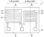
図1に示されるように、容量式湿度センサ1は、基本的には、第1センサ素子(湿度センサ素子)10及び第2センサ素子(第2容量素子)20を有する。
As shown in FIG. 1, the
詳しくは、図2及び図3にそれぞれ示されるように、第1センサ素子10及び第2センサ素子20は、例えばシリコン(Si)からなる同一の半導体基板30上表面に形成されている。また、例えば酸化シリコン(SiO2)からなる絶縁膜40がこの半導体基板30上表面に形成されており、湿度センサ1を取り巻く雰囲気の相対湿度を検出するための電極(一対の電極)10a及び10b並びに20a及び20bが、例えばAl(アルミニウム)等の金属から同一平面上に離間して対向するようにこの絶縁膜40上にそれぞれ形成されている。なお、これら電極10a〜20bの形成材料としては、他にも、Al−Si合金(AlにSiを微量に含有させたもの)、Ti、Au、Cu、多結晶シリコン(Poly−Si)などを使用することができる。また、こうした電極10a〜20bの形状は特に限定されることなく任意であるが、本実施の形態では、櫛歯形状を採用している。これにより、電極10a〜20bそれぞれの櫛歯部が噛み合って対向するため、電極全体としての配置面積を極力小さくしつつ、対向面積を大きくすることができる。そしてひいては、湿度センサ1を取り巻く雰囲気の相対湿度の検出精度を向上することができる。
Specifically, as shown in FIGS. 2 and 3, the
また、図2及び図3に示されるように、後に詳述する感湿膜(感湿部材)60が吸着した水分や雰囲気に含まれる水分による腐食から櫛歯電極10a〜20bを保護するため、保護膜50が、これら櫛歯電極10a〜20b上に、例えば窒化シリコン(SiN)から形成されている。なお、本実施の形態では、保護膜50は、櫛歯電極10a及び10b並びにこれら電極間を覆うように(図2参照)、また、櫛歯電極20a及び20b並びにこれら電極間を覆うように(図3参照)、それぞれ形成されている。なお、少なくとも、櫛歯電極10a〜20bが保護膜50に覆われていれば、腐食から保護することはできる。
Also, as shown in FIGS. 2 and 3, in order to protect the
さらに、図1及び図2に示されるように、第1センサ素子10側の保護膜50上には、雰囲気に含まれる水分を吸着するための多数の細孔を有する感湿膜60が無機材料を用いて形成されている。この感湿膜60は、保護膜50と同様に、櫛歯電極10a及び10b並びにこれら電極間を覆うように形成されている。また、こうした感湿膜60は、例えばディップなどの方法により、櫛歯電極10a〜20bが形成された半導体基板30上に成膜され、形成される。なお、こうした感湿膜60の形成方法は任意である。
Further, as shown in FIGS. 1 and 2, a moisture
また、雰囲気に含まれる水分が感湿膜60の細孔内部に取り込まれると、感湿膜60自体の誘電率は変化しないものの、吸着した水分も含めた感湿膜60全体の誘電率は、水分の誘電率が大きいため、吸着した水分量に応じて大きく変化する。そのため、櫛歯電極10a及び10b間の静電容量値も変化する。このようにして、雰囲気の湿度変化は、櫛歯電極10a及び10b間の容量値の変化として捉えられている。なお、こうした感湿膜60が有する特性等については後述する。また、図1及び図3に示されるように、第2センサ素子20側の保護膜50上には、先の第1センサ素子10側の保護膜50上とは異なり、感湿膜は形成されていない。そのため、櫛歯電極20a及び20b間の容量値は、雰囲気の湿度変化によって変化しない。
Further, when moisture contained in the atmosphere is taken into the pores of the moisture
一方、図1〜図3においては図示を割愛しているが、第1及び第2センサ素子10及び20の出力信号を処理する処理回路が、半導体基板30の表層部に形成されている。この処理回路は、櫛歯電極10a及び10bと櫛歯電極20a及び20bとの容量差を電圧に変換するスイッチドキャパシタ回路(CV変換回路)、このスイッチドキャパシタ回路の出力電圧値であるCV変換値を所定増幅率で増幅する増幅器、この増幅器の増幅率を切り換える切替回路等々を有している。なお、こうした処理回路についても後述する。
On the other hand, although not shown in FIGS. 1 to 3, a processing circuit for processing the output signals of the first and
ところで、課題の欄にも記述したように、こうした湿度センサの感湿膜を形成する材料として一般的な、例えばポリイミド系樹脂等の高分子有機材料は、微視的には、鎖状に長く連なった無数の分子群が互いに密に絡み合った状態にある。そうした感湿膜を有する湿度センサが例えば温度65℃、相対湿度90%の高湿な雰囲気中に長期間に渡って置かれると、同一の湿度下でありながら、雰囲気に含まれる水分子をより多く内部に取り込むようになる。いわゆる膨潤現象が生じる。この膨潤現象が生じると、同一の相対湿度下であっても、センサ出力値が増大してしまい、ひいては、こうした湿度センサのセンサ出力値の変動は、雰囲気の相対湿度の検出精度を低下させてしまう。 By the way, as described in the problem section, a polymer organic material such as a polyimide resin, which is a general material for forming a moisture sensitive film of such a humidity sensor, is microscopically long in a chain shape. Innumerable molecular groups are intertwined with each other. When a humidity sensor having such a moisture sensitive film is placed in a high humidity atmosphere of, for example, a temperature of 65 ° C. and a relative humidity of 90% for a long period of time, water molecules contained in the atmosphere are more removed even under the same humidity. Many will come inside. A so-called swelling phenomenon occurs. When this swelling phenomenon occurs, the sensor output value increases even under the same relative humidity. As a result, the fluctuation of the sensor output value of the humidity sensor decreases the detection accuracy of the relative humidity of the atmosphere. End up.
しかしながら、無機材料にあっては、一般に、いわゆる膨潤現象は生じない。すなわち、無機材料は、有機材料と比較して、その物性が安定しており、長期間にわたって変化しない。したがって、既述したように、本実施の形態では、そうした無機材料から形成された感湿膜60を用いるため、たとえ長期間経過した場合であっても、雰囲気の相対湿度について、当初の検出精度を長期間に渡って維持することができるようになる。
However, in general, so-called swelling phenomenon does not occur in inorganic materials. That is, the inorganic material has stable physical properties as compared with the organic material and does not change over a long period of time. Therefore, as described above, in the present embodiment, since the moisture
また、所定相対湿度よりも低い相対湿度の雰囲気下では、感湿膜60の細孔内部まで浸入する水分子は少ないものの、所定相対湿度よりも高い相対湿度の雰囲気下では、感湿膜60の細孔内部まで浸入する水分子が急増する現象である、いわゆる毛管凝集現象が知られている。なお、感湿膜60の細孔内部まで水分子が浸入することは、感湿膜60に吸着される水分子、すなわち、誘電率や容量値が急増することを意味する。そして、この毛管凝集現象が生じる所定相対湿度は細孔径(直径)の分布に大きく関係することが、発明者らによって確認されている。
In addition, in the atmosphere of relative humidity lower than the predetermined relative humidity, there are few water molecules entering the inside of the pores of the moisture
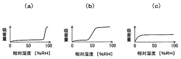
以下、図4及び図5を併せ参照して、毛管凝集現象が生じる所定相対湿度と、細孔径の分布との関係について説明する。なお、図4は、感湿膜60を構成する無機材料の細孔径のばらつきの分布を示すものであり、図5(a)〜(c)は、細孔径のばらつきの分布態様の別に、相対湿度と水分の吸着量との関係を示すものである。また、こうした毛管凝集現象を示す式として一般的なケルビン式が知られている。
Hereinafter, the relationship between the predetermined relative humidity at which the capillary aggregation phenomenon occurs and the pore size distribution will be described with reference to FIGS. 4 and 5 together. FIG. 4 shows the distribution of variation in pore diameter of the inorganic material constituting the moisture
図4に曲線aとして実線にて示すように、感湿膜60を形成する無機材料の細孔径を例えば「10〜11nm」というごく狭い範囲内に収めると、感湿膜60に吸着される水分と相対湿度との間に、図5(a)のような関係が生じる。すなわち、図5(a)に示されるように、雰囲気の相対湿度がおよそ「0〜5%」であるとき、感湿膜60に吸着される水分量は増加し、雰囲気の相対湿度がおよそ「5〜95%」であるとき、感湿膜60に吸着される水分量はほぼ一定となる。そして、雰囲気の相対湿度がおよそ「95〜100%」であるとき、感湿膜60に吸着される水分量が急峻に立ち上がる。すなわち、無機材料の細孔径が例えば「10〜11nm」という範囲に収まると、雰囲気の相対湿度がおよそ「95%」であるときに毛管凝集現象が生じている。
As shown by a solid line as curve a in FIG. 4, when the pore diameter of the inorganic material forming the moisture
感湿膜60がこのような関係を有するとき、相対湿度「95%」よりも高い相対湿度の雰囲気に対しては、湿度変化に対する容量値の変化率が非常に大きいため、当該湿度センサ1の検出感度は非常に高く、したがって、相対湿度の検出精度も非常に高い。一方、相対湿度「95%」よりも低い相対湿度の雰囲気に対しては、湿度変化に対する容量値の変化がほとんどないため、当該湿度センサ1の検出感度は非常に低く、相対湿度の検出は難しい。湿度センサ1は、このような検出特性を有することとなる。
When the humidity
また、図4に曲線bとして一点鎖線にて示すように、感湿膜60を形成する無機材料の細孔径を例えば「3〜10nm」という広い範囲内に収めると、感湿膜60に吸着される水分と相対湿度との間に、図5(b)のような関係生じる。すなわち、図5(b)に示されるように、雰囲気の相対湿度がおよそ「0〜5%」であるとき、感湿膜60に吸着される水分量は増加し、雰囲気の相対湿度がおよそ「5〜45%」であるとき、感湿膜60に吸着される水分量は略一定となる。また、雰囲気の相対湿度がおよそ「45〜55%」であるとき、感湿膜60に吸着される水分量はリニアに変化し、雰囲気の相対湿度がおよそ「55〜100%」であるとき、感湿膜60に吸着される水分量は再びほぼ一定となる。すなわち、無機材料の細孔径が例えば「3〜10nm」という範囲に収まると、雰囲気の相対湿度がおよそ「45%」であるときに毛管凝集現象が生じているとともに、雰囲気の相対湿度がおよそ「55%」であるときに大部分の細孔内部に水分が浸入し飽和している。
Further, as shown by a dashed line in FIG. 4 as a curve b, when the pore diameter of the inorganic material forming the moisture
感湿膜60がこのような関係を有するとき、相対湿度「45%」に満たない相対湿度の雰囲気に対しては、湿度変化に対する容量値の変化がほとんどないため、当該湿度センサ1の検出感度は非常に低く、相対湿度の検出は難しい。一方、相対湿度「45〜55%」に収まる相対湿度の雰囲気に対しては、湿度変化に対する容量値の変化率が大きいため、当該湿度センサ1の検出感度は高く、したがって、相対湿度の検出精度も高い。他方、相対湿度「55%」を超える相対湿度の雰囲気に対しては、湿度変化に対する容量値の変化がほとんどないため、当該湿度センサ1の検出感度は非常に低く、相対湿度の検出は難しい。湿度センサ1は、このような検出特性を有することとなる。
When the humidity-
また、図4に曲線cとして二点鎖線にて示すように、感湿膜60を形成する無機材料の細孔径を例えば「1〜2nm」という、ごく狭い範囲内に収めると、感湿膜60に吸着される水分と相対湿度との間には、図5(c)のような関係が生じる。すなわち、図5(c)に示されるように、雰囲気の相対湿度がおよそ「0〜10%」であるとき、感湿膜60に吸着される水分量は増加し、雰囲気の相対湿度がおよそ「10〜100%」であるとき、感湿膜60に吸着される水分量は略一定となる。すなわち、無機材料の細孔径が例えば「1〜2nm」という範囲に収まると、雰囲気の相対湿度がおよそ「0%」であるときにすでに毛管凝集現象が生じているとともに、雰囲気の相対湿度がおよそ「10%」であるときに大部分の細孔内部に水分が浸入し飽和している。
Further, as shown by a two-dot chain line as a curve c in FIG. 4, when the pore diameter of the inorganic material forming the moisture
感湿膜60がこのような関係を有するとき、相対湿度「10%」に満たない相対湿度の雰囲気に対しては、湿度変化に対する容量値の変化が大きいため、当該湿度センサ1の検出感度は高く、したがって、相対湿度の検出精度も高い。一方、相対湿度「10%」を超える相対湿度の雰囲気に対しては、湿度変化に対する容量値の変化がほとんどないため、当該湿度センサ1の検出感度は非常に低く、相対湿度の検出は難しい。湿度センサ1は、このような検出特性を有することとなる。
When the humidity-
また、従来の高分子有機物からなる感湿膜を有する湿度センサでは、相対湿度がおよそ「5〜90%」の雰囲気において一律の検出精度をもって相対湿度を検出することはできるものの、相対湿度がおよそ「95%」よりも高い雰囲気においては、湿度変化に対する容量値の変化率が変化してしまうため、高い検出精度をもって相対湿度を検出することは難しかった。 In addition, in a humidity sensor having a humidity sensitive film made of a conventional polymer organic substance, although relative humidity can be detected with uniform detection accuracy in an atmosphere where the relative humidity is approximately “5-90%”, the relative humidity is approximately In an atmosphere higher than “95%”, since the rate of change of the capacitance value with respect to the change in humidity changes, it is difficult to detect the relative humidity with high detection accuracy.
そこで、本実施の形態では、感湿膜60を形成する無機材料の細孔径を例えば「10〜11nm」という範囲に収め、図5(a)に示す関係を湿度センサ1に持たせることにより、そうした相対湿度が高い雰囲気に対しても高い検出精度をもって相対湿度を検出しようとしている。
Therefore, in the present embodiment, the pore diameter of the inorganic material forming the moisture-
次に、図6〜図8を併せ参照して、処理回路について詳述する。なお、図6は、本実施の形態の湿度センサ1の等価回路の一例を示した回路図である。
Next, the processing circuit will be described in detail with reference to FIGS. FIG. 6 is a circuit diagram showing an example of an equivalent circuit of the
図6に示されるように、また既述したように、湿度センサ1は、処理回路として、基本的に、雰囲気の相対湿度に応じて容量値が変化する可変容量C10(第1センサ素子10に相当(図1参照))と容量値が変化しない固定容量C20(第2センサ素子20に相当(図1))との容量差を電圧値に変換するSC(スイッチドキャパシタ)回路70、増幅率を切り換える切替回路80、例えば「60倍」の増幅率に設定された増幅回路90a、及び、例えば「12倍」の増幅率に設定された増幅回路90b等々を備える。
As shown in FIG. 6 and as described above, the
詳しくは、SC回路70は、図6に示すように、例えば「5V」の同一の振幅で且つ180度の位相差を有する矩形波である搬送波1及び搬送波2を可変容量C10及び固定容量C20に対してそれぞれ印加する発振回路701、例えば「2.5V」のバイアス電圧を出力する基準電圧源702、可変容量C10及び固定容量C20の中点電位とバイアス電圧とを差動増幅する差動増幅回路703、所定容量を有するコンデンサ704、アナログスイッチ705及び図示しないサンプルホールド回路等々を備える。
Specifically, as shown in FIG. 6, the
このように構成されたSC回路70で実行されるCV変換の一例を図7にタイミングチャートとして示す。この図7に示されるように、SC回路70で実行されるCV変換は、「リセット→サンプルホールド→搬送波切替→サンプルホールド」を一周期として、この周期が約10μ秒ごとに実行される。
An example of CV conversion executed by the
まず、図7(a)に示されるように、例えば時刻t11においてアナログスイッチがオンされると、コンデンサ704が放電される(リセット)。また、図7(b)及び(c)に示されるように、このコンデンサ704の放電と同時に、搬送波1が立ち上げられるとともに搬送波2が立ち下げられる。このとき、関係「可変容量C10>固定容量C20」と、可変容量C10の発振回路701側の電極10a(図1参照)及び固定容量C20の発振回路701側の電極20b(図1参照)それぞれに印加される電圧とに応じて、これら可変容量C10及び固定容量C20が充電される。ちなみに、可変容量C10の差動増幅回路703側の電極10b(図1参照)及び固定容量C20の差動増幅回路703側の電極20a(図1参照)の電荷量は、負の電荷が多い状態になる。
First, as shown in FIG. 7A, for example, when the analog switch is turned on at time t11, the
次に、図7(a)に示されるように、例えば時刻t12においてアナログスイッチがオフされると、可変容量C10の電極10b及び固定容量C20の電極20a並びにコンデンサ704の差動増幅回路703の反転入力端子側の電極によって閉回路が構成され、先の時刻t11から時刻t12までに蓄えられた電荷量は保存される。そうした状態にある例えば時刻t13において、SC回路70の出力電圧値Vsがサンプリングされ(図7(d))、適宜の記憶保持手段に一時的に記憶される。
Next, as shown in FIG. 7A, for example, when the analog switch is turned off at time t12, the
そして、図7(b)及び(c)に示されるように、例えば時刻t14において、搬送波1が立ち下げられると同時に搬送波2が立ち上げられる。このように搬送波が反転されると、可変容量C10の電極10b及び固定容量C20の電極20aの電荷量は、正の電荷が多い状態になる。しかしながら、既述したように、可変容量C10の電極10b及び固定容量C20の電極20a並びにコンデンサ704の差動回路703の反転入力端子側の電極によって閉回路が構成されていることから、この閉回路にある電荷量は保存されている。そのため、可変容量C10の電極10b及び固定容量C20の電極20aの電荷の平衡状態から溢れた負の電荷が、コンデンサ704の差動増幅回路703の反転入力端子側の電極に移動する。この電荷の移動により、コンデンサ704の差動増幅回路703の出力端子側の電極には、正の電荷が蓄えられることになり、「蓄えられる電荷量=容量×電位差」の関係から、移動した電荷量に比例し、コンデンサ704の容量値に反比例した電圧値分だけ、SC回路70の出力電圧値Vsが変動することになる。
Then, as shown in FIGS. 7B and 7C, for example, at time t14, the
このように変動した出力電圧値VsがSC回路70の出力端子706から出力される(図7(e))。そして、例えば時刻t16において、電荷の移動が終了し安定したところで、サンプリングされ(図7(d))、適宜の記憶保持手段に一時的に記憶される。そして、続く時刻t17から、この周期が同様に開始される。
The output voltage value Vs that fluctuates in this way is output from the
なお、最終的には、上記時刻t16においてサンプリングした電圧値から、上記時刻t13においてサンプリングした電圧値を差動演算した値に基づいて、雰囲気の相対湿度が検出される。また、本実施の形態では、感湿膜60が先の図5(a)に示す特性を有するため、雰囲気の相対湿度と出力端子706における出力電圧値Vsとの関係は、例えば図8(a)に示す関係となっている。すなわち、相対湿度が「0〜95%」の範囲においては、出力電圧値Vsは「0〜50mV」で直線状となり、相対湿度が「95〜100%」の範囲においては、出力電圧値Vsは「50〜250mV」で直線状となる。
Finally, the relative humidity of the atmosphere is detected from the voltage value sampled at time t16, based on a value obtained by differentially calculating the voltage value sampled at time t13. In this embodiment, since the moisture
また、先の図6に示すように、切替回路80は、例えば「50mV」のバイアス電圧を出力する基準電圧源801と出力端子706における出力電圧値Vsとを比較するとともに、論理Hiレベルに対応する電圧と論理Loレベルに対応する電圧との間で比較結果に応じて出力電圧を出力する比較器802、比較器802の出力電圧を反転するインバータ803、論理Hiレベルに対応する電圧が比較器802から印加されるとオンとなるアナログスイッチ804、論理Hiレベルに対応する電圧がインバータ803から印加されるとオンとなるアナログスイッチ805、並びに、出力端子806等々を備える。なお、基準電圧源801のバイアス電圧は、先の図8(a)に示した、直線の特性が変わる変曲点に相当する電圧値(すなわち「50mV」)に設定されている。
Further, as shown in FIG. 6, the switching
このように構成された切替回路80で実行される、後段に接続される増幅回路90a及び90bの切替動作、すなわち、増幅率の切替動作の一例を説明する。
An example of the switching operation of the
相対湿度が「0〜95%」の範囲においては、まず、既述したように、「0〜50mV」の出力電圧値Vsが出力端子706から出力され、切替回路80に入力される。次に、SC回路70の出力電圧値と上記バイアス電圧とが比較器802において比較され、バイアス電圧の方が高いため、論理Hiに対応する電圧値が比較器802から出力される。こうして論理Hiに対応する電圧値が出力されると、アナログスイッチ804がオンとなる一方、アナログスイッチ805はオフとなる。そして、出力端子706の出力電圧値Vsは、増幅回路90aにおいて、例えば「60倍」に増幅される。したがって、増幅回路90aの出力端子901aにおける出力電圧は、図8(b)に示すように、相対湿度「0〜95%」に対して「1.0〜4.0V」の範囲で直線状に変化することとなる。なお、増幅回路90a内でオフセット調整が行われるため、出力端子901aにおける出力電圧は、相対湿度「95〜100%」に対して、一定電圧「1.0V」となる。
When the relative humidity is in the range of “0 to 95%”, first, the output voltage value Vs of “0 to 50 mV” is output from the
一方、相対湿度が「95〜100%」の範囲においては、まず、既述したように、「50〜250mV」の出力電圧値Vsが出力端子706から出力され、切替回路80に入力される。次に、SC回路70の出力電圧値と上記バイアス電圧とが比較器802において比較され、バイアス電圧の方が低いため、論理Loに対応する電圧値が比較器802から出力される。こうして論理Loに対応する電圧値が出力されると、アナログスイッチ804がオフとなる一方、アナログスイッチ805はオンとなる。そして、出力端子706の出力電圧値Vsは、増幅回路90bにおいて、例えば「12倍」に増幅される。したがって、増幅回路90bの出力端子901bから出力される出力電圧は、図8(c)に示すように、相対湿度「95〜100%」に対して「1.0〜4.0V」の範囲で直線状に変化することとなる。なお、増幅回路90a内でオフセット調整が行われるため、出力端子901bにおける出力電圧は、相対湿度「0〜95%」に対して、一定電圧「1.0V」となる。
On the other hand, in the range where the relative humidity is “95 to 100%”, first, as described above, the output voltage value Vs of “50 to 250 mV” is output from the
このように、切替回路80の出力端子806における出力電圧、増幅回路90aの出力端子901aにおける出力電圧、及び、増幅回路90bの出力端子901bにおける出力電圧に基づくことで、雰囲気の相対湿度に拘わらず、換言すれば、広範囲にわたって、高い精度をもって相対湿度を検出することができるようになる。
Thus, based on the output voltage at the
こうした湿度センサ1は、例えば車両の窓ガラスなどのくもりを防止するべく、空調機の制御に用いることができる。詳しくは、湿度センサ1は、高い相対湿度の雰囲気下においても、高精度をもって相対湿度を検出することができるため、窓ガラスに結露が生じる直前(相対湿度が100%付近)に、空調機を駆動することで相対湿度を低下させ、結露を未然に防止することができるようになる。すなわち、当該湿度センサ1は、結露センサとしても使用することが可能である。
Such a
なお、本発明に係る湿度センサは、上記実施の形態で例示した構成に限られるものではなく、本実施の形態を適宜変更した例えば次の形態として実施することもできる。 Note that the humidity sensor according to the present invention is not limited to the configuration exemplified in the above embodiment, and may be implemented as, for example, the following form in which the present embodiment is appropriately changed.
上記実施の形態では、相対湿度が95%よりも高い相対湿度を検出するための増幅率に設定された増幅回路90bと、相対湿度が95%よりも低い相対湿度を検出するための増幅率に設定された増幅回路90aとを切り換えていた。すなわち、増幅回路を2つ使用して増幅率を切り換えていたがこれに限らない。他に例えば、先の図6に対応する図として図9に示すように、増幅回路を2つ使用するとともに切替回路80を割愛した湿度センサ1aとしてもよい。この場合、増幅回路90aの出力端子901aにおける出力電圧に基づき、相対湿度「5〜95%」の検出が可能となり、増幅回路90bの出力端子901bにおける出力電圧に基づき、相対湿度「95〜100%」の検出が可能となる。
In the above embodiment, the
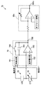
また、他に例えば、先の図6に対応する図として図10に示すように、切替回路80を割愛するとともに、増幅回路90a及び90bに替えて増幅率を可変設定することのできる増幅回路90cを備えた湿度センサ1bとしてもよい。これにより、増幅回路の数を減らすことができ、湿度センサの体格の小型化を図ることができる。さらには、そうした増幅回路90c自体を割愛した構成としてもよい。これにより、湿度センサの体格のさらなる小型化を図ることができる。
In addition, for example, as shown in FIG. 10 as a diagram corresponding to FIG. 6, the switching
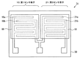
上記実施の形態(変形例を含む)では、櫛歯電極20a及び20bを有するとともに相対湿度の変化によって容量値が変化しない第2センサ素子20を備えていたが、これに限らない。他に例えば、図1に対応する図として図11に示すように、第2センサ素子20に替えて、櫛歯電極21a及び21bを有するとともに、高分子有機物からなる感湿膜61を有する第3センサ素子(第3容量素子)21を備えた湿度センサ1cとしてもよい。こうした第3センサ素子21は、従来の湿度センサ素子に相当し、その容量値は、相対湿度に対してほぼ直線状に変化する。そのため、既述したように、相対湿度がおよそ「5%〜90%」の雰囲気において一律の検出精度をもって相対湿度を検出することはできる。一方、第1センサ素子10は、これも既述したように、相対湿度「95%」よりも高い相対湿度の雰囲気に対しては、湿度変化に対する容量値の変化率が非常に大きいため、相対湿度の検出精度も非常に高い。しかし、相対湿度「95%」よりも低い相対湿度の雰囲気に対しては、湿度変化に対する容量値の変化がほとんどないため、相対湿度の検出精度はあまり良くない。その点、第1センサ素子10と第3センサ素子21を併用する上記変形例によれば、「5〜95%」の相対湿度範囲に対しては、従来の湿度センサと同程度の検出精度をもって、「95〜100%」の相対湿度範囲に対しては、従来の湿度センサよりも高い検出精度をもって、相対湿度を検出することができるようになる。
In the above-described embodiment (including modifications), the
上記実施の形態(変形例を含む)では、第1センサ素子10と第2センサ素子20との組み合わせや、第1センサ素子10と第3センサ素子21との組み合わせによって、湿度センサを構成していたが、こうした2素子方式に限らない。他に例えば、図1及び図11に対応する図として図12に示すように、第2センサ素子20及び第3センサ素子21を割愛した湿度センサ1dとしてもよい。この場合、2素子間の容量差を電圧に変換するCV変換回路を用いていたが、こうした単一素子方式においては、CV変換回路に限らず、一般的な共振回路を用いることとしてもよい。詳しくは、第1センサ素子(容量)と適宜の抵抗器とを用いてRC発振回路を構成するとともに、湿度変化に伴う第1センサ素子の容量変化、この容量変化に伴う共振周波数の変化に基づき、相対湿度を検出することもできる。
In the above embodiment (including modifications), the humidity sensor is configured by the combination of the
上記実施の形態(変形例を含む)では、一対の電極として、櫛歯電極10a〜21bを採用していたが、電極形状については、既述した通り、これに限らず、任意である。他に例えば、一対の電極として、その一対の電極間に感湿膜を挟むように上下に配置され、平板形状に形成された平板電極を採用してもよい。
In the said embodiment (a modification is included), although the comb-
上記実施の形態(変形例を含む)では、感湿膜60を形成する無機材料の細孔径を例えば「10〜11nm」という範囲に収め、先の図5(a)に示す関係を湿度センサに持たせていたが、細孔径の設定範囲はこれに限らない。他に例えば「10〜50nm」という範囲に収めることとしても、先の図5(a)に示す関係に準じた関係を有することはできる。
In the above embodiment (including modifications), the pore diameter of the inorganic material forming the moisture-
なお、特に図5(a)に示す関係に準じた関係でなくてもよいのであれば、先の図4に曲線bとして示したように、感湿膜を形成する無機材料の細孔径を例えば「3〜10nm」という範囲に収め、先の図5(b)に示す関係を湿度センサに持たせることとしてもよい。あるいは、先の図4に曲線cとして示したように、感湿膜を形成する無機材料の細孔径を例えば「1〜2nm」という範囲に収め、先の図5(c)に示す関係を湿度センサに持たせることとしてもよい。高い検出精度で検出したい所望の相対湿度範囲に応じて、無機材料の細孔径の範囲を設定してよい。 If the relationship according to the relationship shown in FIG. 5 (a) is not particularly required, the pore diameter of the inorganic material forming the moisture sensitive film is, for example, as shown by the curve b in FIG. The humidity sensor may have the relationship shown in FIG. 5B within the range of “3 to 10 nm”. Alternatively, as indicated by the curve c in FIG. 4 above, the pore diameter of the inorganic material forming the moisture sensitive film is within a range of “1-2 nm”, for example, and the relationship shown in FIG. The sensor may be provided. Depending on the desired relative humidity range to be detected with high detection accuracy, the pore diameter range of the inorganic material may be set.
(第2の実施の形態)
以下、図13を参照しつつ、本発明に係る湿度センサの第2の実施の形態について説明する。なお、図13は、本実施の形態の湿度センサの斜視図である。
(Second Embodiment)
Hereinafter, a second embodiment of the humidity sensor according to the present invention will be described with reference to FIG. FIG. 13 is a perspective view of the humidity sensor according to the present embodiment.
この図13に示されるように、本実施の形態の湿度センサ2は、基本的に、カンチレバー部(感湿部材)62を振動可能に1箇所にて支持する支持部材31、感湿材料を用いて形成されるとともに吸着した水分の重さに応じた共振周波数で振動するカンチレバー部62、カンチレバー部62の振幅に応じた大きさの電気信号を処理回路(図示略)に出力する歪ゲージ11(検出部材)及び歪ゲージ11の出力信号を処理する処理回路を備える。
As shown in FIG. 13, the
このうち、カンチレバー部62は、図13に示されるように、支持部材31の側壁から突出した略直方体形状に感湿材料を用いて形成される。そして、カンチレバー部62は、支持部材31による支持点を基点として、主に、上下方向に振動可能となっている。なお、本実施の形態では、カンチレバー部62を形成する感湿材料として、水分を吸着するための多数の細孔を有する無機材料が採用されている。また、カンチレバー部62の縦の長さをD、横の長さをL、幅をW、ρをカンチレバー部62の密度、gを重力加速度、Eをヤング率、Iを断面2次モーメントとすると、カンチレバー部62の一次振動の共振周波数は、下式(1)にて表される。
Among these, as shown in FIG. 13, the

また、歪ゲージ11は、図13に示されるように、支持部材31がカンチレバー部62を支持する箇所の上表面に、貼付されている。そして、歪ゲージ11は、カンチレバー部62が上下方向に振動すると、その振幅に応じた大きさの電気信号を処理回路(図示略)に出力する。
Further, as shown in FIG. 13, the
処理回路は、このようにして出力された歪ゲージ11の出力信号を取り込むとともに、該出力信号を適宜に処理し、共振周波数を検出する。そして、この共振周波数に基づき、雰囲気の相対湿度を検出する。
The processing circuit takes in the output signal of the
なお、本発明に係る湿度センサは、上記第2の実施の形態で例示した構成に限られるものではなく、本実施の形態を適宜変更した例えば次の形態として実施することもできる。 Note that the humidity sensor according to the present invention is not limited to the configuration exemplified in the second embodiment, and can be implemented as, for example, the following form in which the present embodiment is appropriately changed.
上記第2の実施の形態では、検出部材として歪ゲージ11を採用したが、これに限らない。他に例えば、圧電素子などを採用することもできる。要は、カンチレバー部62の振幅を電気信号に変換することができるのであればよい。
In the second embodiment, the
上記第2の実施の形態では、カンチレバー部62は、支持部材31に1箇所のみで支持されていたが、複数個所で支持されるように構成してもよい。要は、感湿部材が、吸着した水分の重さに応じた共振周波数で振動することができれば、支持態様は任意である。
In the second embodiment, the
(他の実施の形態)
上記第1実施の形態では、相対湿度の検出原理として容量式を採用した湿度センサについて説明し、上記第2の実施の形態では、相対湿度の検出原理として振動式を採用した湿度センサについて説明したが、相対湿度の検出原理については、これら容量式あるいは振動式に限らない。検出原理に拘わらず、雰囲気の湿度変化を感湿部材の物理量の変化として検出する湿度センサにおいて、感湿部材が、水分を吸着するための多数の細孔を有する無機材料から形成されていれば、所期の目的を達成することはできる。
(Other embodiments)
In the first embodiment, a humidity sensor that employs a capacitance type as the detection principle of relative humidity is described. In the second embodiment, a humidity sensor that uses a vibration type as the detection principle of relative humidity is described. However, the relative humidity detection principle is not limited to the capacity type or the vibration type. Regardless of the detection principle, in a humidity sensor that detects a change in the humidity of the atmosphere as a change in the physical quantity of the moisture sensitive member, if the moisture sensitive member is formed of an inorganic material having a large number of pores for adsorbing moisture Can achieve the intended purpose.
1、1a、1b、1c、2…湿度センサ、10…第1センサ素子(湿度センサ素子)、10a、10b…櫛歯電極(一対の電極)、11…歪ゲージ(検出部材)、20…第2センサ素子(第2容量素子)、20a、20b…櫛歯電極(一対の電極)、21…第3センサ素子、30…半導体基板、31…支持部材、40…絶縁膜、50…保護膜、60…感湿膜(感湿部材)、61…感湿膜、62…カンチレバー部(感湿部材)、70…スイッチドキャパシタ回路(処理回路)、701…発振回路、702…基準電圧源、703…オペアンプ、704…キャパシタ、705…アナログスイッチ、80…切替回路、801…オペアンプ、802…基準電圧源、803…アナログスイッチ、804…インバータ、805…アナログスイッチ、90a、90b…増幅器、901a、901b…端子。
DESCRIPTION OF
Claims (8)
前記感湿部材は、水分を吸着するための多数の細孔を有する無機材料から形成されて水分を吸着することによってその誘電率が変化する感湿膜であり、
前記検出部材は、前記感湿膜の容量値の変化を検出するための一対の電極であり、
当該湿度センサは、前記感湿膜の誘電率の変化に基づいて相対湿度を検出する容量式の湿度センサであって、
前記細孔の直径は、雰囲気に含まれる水分子が急激に細孔の内部に浸入する現象である毛管凝集現象が所定相対湿度において生じる直径に設定され、
前記細孔の直径は、「10〜50nm」に設定され、
前記細孔の直径の分布が、直径を中心として±1nm以内に設定され、
前記所定相対湿度よりも高い相対湿度の雰囲気における、湿度変化に対する容量値の変化率は、前記所定相対湿度よりも低い相対湿度の雰囲気における、湿度変化に対する容量値の変化率よりも大きいことを特徴とする湿度センサ。 A humidity sensor element having a humidity sensing member whose physical quantity changes by adsorbing moisture, a detection member for detecting a change in the physical quantity, and a processing circuit for processing an output signal of the detection member, and an atmosphere In a humidity sensor that detects a change in humidity as a change in the physical quantity ,
The humidity-sensitive member is a moisture sensitive film whose dielectric constant is changed by being formed of an inorganic material having a large number of pores for adsorbing moisture to adsorb moisture,
The detection member is a pair of electrodes for detecting a change in the capacitance value of the moisture sensitive film ,
The humidity sensor is a capacitive humidity sensor that detects relative humidity based on a change in dielectric constant of the moisture sensitive film,
The diameter of the pore is set to a diameter at which a capillary agglomeration phenomenon, which is a phenomenon in which water molecules contained in the atmosphere suddenly enter the inside of the pore, occurs at a predetermined relative humidity,
The diameter of the pore is set to “10-50 nm”,
The pore diameter distribution is set within ± 1 nm centered on the diameter,
The change rate of the capacity value with respect to humidity change in an atmosphere with a relative humidity higher than the predetermined relative humidity is larger than the change rate of the capacitance value with respect to humidity change in an atmosphere with a relative humidity lower than the predetermined relative humidity. Humidity sensor.
前記処理回路は、この第2容量素子の一対の電極と前記湿度センサ素子を構成する一対の電極との容量差を電圧に変換するCV変換回路を含み、
前記CV変換回路の出力電圧値であるCV変換値に基づいて雰囲気の相対湿度を検出することを特徴とする請求項1〜3のいずれか一項に記載の湿度センサ。 A second capacitive element that has a pair of electrodes and whose capacitance value does not change depending on the relative humidity;
The processing circuit includes a CV conversion circuit that converts a capacitance difference between the pair of electrodes of the second capacitive element and the pair of electrodes constituting the humidity sensor element into a voltage,
The humidity sensor according to any one of claims 1 to 3 , wherein the relative humidity of the atmosphere is detected based on a CV conversion value that is an output voltage value of the CV conversion circuit.
前記処理回路は、この第3容量素子の一対の電極と前記湿度センサ素子を構成する一対の電極との容量差を電圧に変換するCV変換回路を含み、
前記CV変換回路の出力電圧値であるCV変換値に基づいて雰囲気の相対湿度を検出することを特徴とする請求項1〜3のいずれか一項に記載の湿度センサ。 A third capacitive element further comprising a moisture sensitive film made of a polymer organic material whose dielectric constant changes by adsorbing moisture, and a pair of electrodes covered by the moisture sensitive film;
The processing circuit includes a CV conversion circuit that converts a capacitance difference between the pair of electrodes of the third capacitive element and the pair of electrodes constituting the humidity sensor element into a voltage,
The humidity sensor according to any one of claims 1 to 3 , wherein the relative humidity of the atmosphere is detected based on a CV conversion value that is an output voltage value of the CV conversion circuit.
Priority Applications (2)
| Application Number | Priority Date | Filing Date | Title |
|---|---|---|---|
| JP2007112136A JP4386295B2 (en) | 2007-04-20 | 2007-04-20 | Humidity sensor |
| US12/081,513 US7971482B2 (en) | 2007-04-20 | 2008-04-17 | Humidity sensor |
Applications Claiming Priority (1)
| Application Number | Priority Date | Filing Date | Title |
|---|---|---|---|
| JP2007112136A JP4386295B2 (en) | 2007-04-20 | 2007-04-20 | Humidity sensor |
Publications (3)
| Publication Number | Publication Date |
|---|---|
| JP2008268025A JP2008268025A (en) | 2008-11-06 |
| JP2008268025A5 JP2008268025A5 (en) | 2009-03-19 |
| JP4386295B2 true JP4386295B2 (en) | 2009-12-16 |
Family
ID=39870875
Family Applications (1)
| Application Number | Title | Priority Date | Filing Date |
|---|---|---|---|
| JP2007112136A Expired - Fee Related JP4386295B2 (en) | 2007-04-20 | 2007-04-20 | Humidity sensor |
Country Status (2)
| Country | Link |
|---|---|
| US (1) | US7971482B2 (en) |
| JP (1) | JP4386295B2 (en) |
Families Citing this family (30)
| Publication number | Priority date | Publication date | Assignee | Title |
|---|---|---|---|---|
| CN101738422B (en) * | 2009-12-23 | 2012-09-05 | 北京宝力马传感技术有限公司 | Humidity measuring device and method |
| WO2011086685A1 (en) * | 2010-01-15 | 2011-07-21 | トヨタ自動車株式会社 | Voltage detection apparatus |
| US9063067B1 (en) | 2010-11-17 | 2015-06-23 | Alvin P. Schmitt | Moisture sensing devices |
| JP2012198120A (en) | 2011-03-22 | 2012-10-18 | Seiko Epson Corp | Sensor device |
| JP2012198121A (en) * | 2011-03-22 | 2012-10-18 | Seiko Epson Corp | Sensor device and measuring method |
| MY154211A (en) * | 2011-04-26 | 2015-05-15 | Mimos Berhad | A humidity sensor device |
| US9182295B1 (en) * | 2011-09-09 | 2015-11-10 | Sitime Corporation | Circuitry and techniques for resistor-based temperature sensing |
| US9304098B2 (en) * | 2013-02-04 | 2016-04-05 | Veris Industries, Llc | Capacitive humidity sensor with hysteresis compensation |
| US9746438B2 (en) * | 2013-02-06 | 2017-08-29 | Veris Industries, Llc | Humidity sensor with temperature compensation |
| US9234859B2 (en) * | 2013-03-28 | 2016-01-12 | Stmicroelectronics S.R.L. | Integrated device of a capacitive type for detecting humidity, in particular manufactured using a CMOS technology |
| CN103792268B (en) * | 2014-02-19 | 2015-12-09 | 苏州能斯达电子科技有限公司 | A kind of differential capacitance type hydrogen gas sensor |
| CN103792267B (en) * | 2014-02-19 | 2015-12-02 | 苏州能斯达电子科技有限公司 | A kind of differential capacitance type humidity sensor |
| CN104198545B (en) * | 2014-08-20 | 2016-09-07 | 云南师范大学 | Sonde heated type humidity sensor and preparation method thereof and a kind of humidity measuring circuit |
| KR101781687B1 (en) * | 2015-07-23 | 2017-09-25 | 한양대학교 산학협력단 | Deveice for detection and recordation of damages on conductive composite material and method for manufacturing the same |
| CN105527325A (en) * | 2016-01-20 | 2016-04-27 | 中国石油大学(华东) | Humidity sensor based on stannic oxide/graphene-like molybdenum disulfide film |
| RU2647168C2 (en) * | 2016-07-19 | 2018-03-14 | Федеральное государственное бюджетное образовательное учреждение высшего образования "Чувашский государственный университет имени И.Н. Ульянова" | Humidity sensor |
| CN106198651A (en) * | 2016-08-31 | 2016-12-07 | 成都市和平科技有限责任公司 | A kind of high accuracy humidity sensor |
| US10364926B2 (en) | 2016-09-02 | 2019-07-30 | Veris Industries, Llc | Endcap for dry pressure insertion probe |
| JP2018147117A (en) * | 2017-03-02 | 2018-09-20 | パナソニックIpマネジメント株式会社 | Sensor circuit, and sensor device with the same |
| CN110006960A (en) * | 2018-01-05 | 2019-07-12 | 张家港万众一芯生物科技有限公司 | Dangerous liquid detection device and detection method based on flexible self-adaptation type interdigital capacitor |
| CN108872321B (en) * | 2018-08-14 | 2021-03-19 | 天津大学 | Moisture content measuring device based on plug-in conductivity sensor |
| JP7234843B2 (en) * | 2018-11-16 | 2023-03-08 | ミネベアミツミ株式会社 | DETECTION DEVICE AND CHARGE-VOLTAGE CONVERSION CIRCUIT |
| US11313824B2 (en) * | 2018-11-16 | 2022-04-26 | Minebea Mitsumi Inc. | Detecting device |
| CN209326840U (en) | 2018-12-27 | 2019-08-30 | 热敏碟公司 | Pressure sensor and pressure transmitter |
| WO2020152501A1 (en) * | 2019-01-23 | 2020-07-30 | Twtg R&D B.V. | Electrical impedance spectrography using a capacitive voltage divider |
| CN110133055A (en) * | 2019-06-25 | 2019-08-16 | 国电龙源电气有限公司 | A kind of detection method of condensation detection device and condensation |
| EP3812754A1 (en) | 2019-10-25 | 2021-04-28 | MEAS France | Inorganic humidity sensor device |
| JP2022069317A (en) | 2020-10-23 | 2022-05-11 | トライポッド・デザイン株式会社 | Device, sensor, sensing method, sensor system, and power generation method |
| EP4159992A1 (en) * | 2021-09-30 | 2023-04-05 | MEAS France | Turbine device |
| CN114441607B (en) * | 2021-12-31 | 2024-04-16 | 深圳市壹号能源科技有限公司 | Humidity monitoring system and method of back-up energy storage system |
Family Cites Families (9)
| Publication number | Priority date | Publication date | Assignee | Title |
|---|---|---|---|---|
| JPS59179366A (en) | 1983-03-31 | 1984-10-11 | Naoto Ootsuki | Typewriter for letters and raised letters |
| JPH0781974B2 (en) | 1988-05-19 | 1995-09-06 | 横河電機株式会社 | Ceramic humidity sensor |
| DE69232149T2 (en) | 1991-12-02 | 2002-06-06 | Canon Kk | gauge |
| JP3398761B2 (en) | 2000-08-09 | 2003-04-21 | 独立行政法人産業技術総合研究所 | Humidity control material showing excellent water absorption behavior under high humidity conditions |
| JP2002243690A (en) | 2001-02-20 | 2002-08-28 | Denso Corp | Capacitance type humidity sensor and method for manufacturing the same |
| US6580600B2 (en) | 2001-02-20 | 2003-06-17 | Nippon Soken, Inc. | Capacitance type humidity sensor and manufacturing method of the same |
| JP3803862B2 (en) | 2001-10-23 | 2006-08-02 | 三菱マテリアル株式会社 | Humidity sensor and manufacturing method thereof |
| JP3855950B2 (en) * | 2003-03-19 | 2006-12-13 | 株式会社デンソー | Capacitive humidity sensor |
| JP4455286B2 (en) * | 2004-11-09 | 2010-04-21 | 株式会社日本自動車部品総合研究所 | Capacitive humidity sensor |
-
2007
- 2007-04-20 JP JP2007112136A patent/JP4386295B2/en not_active Expired - Fee Related
-
2008
- 2008-04-17 US US12/081,513 patent/US7971482B2/en not_active Expired - Fee Related
Also Published As
| Publication number | Publication date |
|---|---|
| US20080257037A1 (en) | 2008-10-23 |
| JP2008268025A (en) | 2008-11-06 |
| US7971482B2 (en) | 2011-07-05 |
Similar Documents
| Publication | Publication Date | Title |
|---|---|---|
| JP4386295B2 (en) | Humidity sensor | |
| JP2008268025A5 (en) | ||
| EP2846143B1 (en) | Pressure sensor | |
| EP2203738B1 (en) | Improved structure for capacitive balancing of integrated relative humidity sensor and manufacturing method | |
| AU2007292328B2 (en) | Method and apparatus for controlling the sensitivity and value of a capacitive humidity sensor | |
| TW201617585A (en) | Thin-film resistive-based sensor | |
| US7340941B1 (en) | Dense thin film-based chemical sensors and methods for making and using same | |
| Li et al. | Investigation of capacitive humidity sensing behavior of silicon nanowires | |
| JP2007139447A (en) | Moisture permeability measuring instrument of thin film and moisture permeability measuring method | |
| JP2008039550A (en) | Humidity sensor | |
| KR101322354B1 (en) | Humidity sensor, humidity sensing method and transistor therefor | |
| Eren | Capacitive sensors | |
| US7854159B2 (en) | Sensor and methods for measuring of concentrations of components in a liquid | |
| US20060055502A1 (en) | Humidity sensor | |
| Rittersma et al. | A monitoring instrument with capacitive porous silicon humidity sensors | |
| JPWO2003016920A1 (en) | Drop impact measuring system and acceleration sensor element used in the drop impact measuring system | |
| Plum et al. | Design of a MEMS capacitive chemical sensor based on polymer swelling | |
| KR101103578B1 (en) | Cantilever sensor | |
| JP2005315805A (en) | Sensor system | |
| JPS5967445A (en) | Humidity sensor | |
| US11287395B2 (en) | Capacitive gas sensor | |
| JP2001013160A (en) | Acceleration responding element and acceleration sensor | |
| Liang et al. | Molecular electronic transducer based tilting sensors | |
| KR101187725B1 (en) | Cantilever sensor | |
| JP2001249099A (en) | Electrostatic capacity humidity sensor and humidity measuring instrument |
Legal Events
| Date | Code | Title | Description |
|---|---|---|---|
| A521 | Written amendment |
Free format text: JAPANESE INTERMEDIATE CODE: A523 Effective date: 20090128 |
|
| A621 | Written request for application examination |
Free format text: JAPANESE INTERMEDIATE CODE: A621 Effective date: 20090128 |
|
| A977 | Report on retrieval |
Free format text: JAPANESE INTERMEDIATE CODE: A971007 Effective date: 20090601 |
|
| A131 | Notification of reasons for refusal |
Free format text: JAPANESE INTERMEDIATE CODE: A131 Effective date: 20090707 |
|
| A521 | Written amendment |
Free format text: JAPANESE INTERMEDIATE CODE: A523 Effective date: 20090827 |
|
| TRDD | Decision of grant or rejection written | ||
| A01 | Written decision to grant a patent or to grant a registration (utility model) |
Free format text: JAPANESE INTERMEDIATE CODE: A01 Effective date: 20090924 |
|
| A01 | Written decision to grant a patent or to grant a registration (utility model) |
Free format text: JAPANESE INTERMEDIATE CODE: A01 |
|
| A61 | First payment of annual fees (during grant procedure) |
Free format text: JAPANESE INTERMEDIATE CODE: A61 Effective date: 20090924 |
|
| R150 | Certificate of patent or registration of utility model |
Free format text: JAPANESE INTERMEDIATE CODE: R150 |
|
| FPAY | Renewal fee payment (event date is renewal date of database) |
Free format text: PAYMENT UNTIL: 20121009 Year of fee payment: 3 |
|
| FPAY | Renewal fee payment (event date is renewal date of database) |
Free format text: PAYMENT UNTIL: 20121009 Year of fee payment: 3 |
|
| FPAY | Renewal fee payment (event date is renewal date of database) |
Free format text: PAYMENT UNTIL: 20131009 Year of fee payment: 4 |
|
| R250 | Receipt of annual fees |
Free format text: JAPANESE INTERMEDIATE CODE: R250 |
|
| R250 | Receipt of annual fees |
Free format text: JAPANESE INTERMEDIATE CODE: R250 |
|
| R250 | Receipt of annual fees |
Free format text: JAPANESE INTERMEDIATE CODE: R250 |
|
| R250 | Receipt of annual fees |
Free format text: JAPANESE INTERMEDIATE CODE: R250 |
|
| LAPS | Cancellation because of no payment of annual fees |