EP2846143B1 - Pressure sensor - Google Patents
Pressure sensor Download PDFInfo
- Publication number
- EP2846143B1 EP2846143B1 EP13785081.4A EP13785081A EP2846143B1 EP 2846143 B1 EP2846143 B1 EP 2846143B1 EP 13785081 A EP13785081 A EP 13785081A EP 2846143 B1 EP2846143 B1 EP 2846143B1
- Authority
- EP
- European Patent Office
- Prior art keywords
- pressure
- cantilever
- cavity
- pressure sensor
- gap
- Prior art date
- Legal status (The legal status is an assumption and is not a legal conclusion. Google has not performed a legal analysis and makes no representation as to the accuracy of the status listed.)
- Active
Links
- 238000006073 displacement reaction Methods 0.000 claims description 26
- 238000001514 detection method Methods 0.000 claims description 18
- 238000005259 measurement Methods 0.000 claims description 14
- 230000002093 peripheral effect Effects 0.000 claims description 9
- 239000004065 semiconductor Substances 0.000 claims description 5
- 239000000463 material Substances 0.000 claims description 4
- 238000012360 testing method Methods 0.000 description 41
- 238000012795 verification Methods 0.000 description 41
- 238000010586 diagram Methods 0.000 description 27
- 230000007423 decrease Effects 0.000 description 8
- XUIMIQQOPSSXEZ-UHFFFAOYSA-N Silicon Chemical compound [Si] XUIMIQQOPSSXEZ-UHFFFAOYSA-N 0.000 description 7
- 230000000694 effects Effects 0.000 description 7
- 229910052710 silicon Inorganic materials 0.000 description 7
- 239000010703 silicon Substances 0.000 description 7
- 239000000758 substrate Substances 0.000 description 7
- 238000000034 method Methods 0.000 description 6
- 238000013461 design Methods 0.000 description 4
- 230000005540 biological transmission Effects 0.000 description 2
- 230000003247 decreasing effect Effects 0.000 description 2
- 230000007613 environmental effect Effects 0.000 description 2
- 238000012544 monitoring process Methods 0.000 description 2
- VYPSYNLAJGMNEJ-UHFFFAOYSA-N Silicium dioxide Chemical compound O=[Si]=O VYPSYNLAJGMNEJ-UHFFFAOYSA-N 0.000 description 1
- 230000003321 amplification Effects 0.000 description 1
- 239000004020 conductor Substances 0.000 description 1
- 238000012937 correction Methods 0.000 description 1
- 230000001419 dependent effect Effects 0.000 description 1
- 238000009792 diffusion process Methods 0.000 description 1
- 239000002019 doping agent Substances 0.000 description 1
- BHEPBYXIRTUNPN-UHFFFAOYSA-N hydridophosphorus(.) (triplet) Chemical compound [PH] BHEPBYXIRTUNPN-UHFFFAOYSA-N 0.000 description 1
- 239000012535 impurity Substances 0.000 description 1
- 238000005468 ion implantation Methods 0.000 description 1
- 238000003199 nucleic acid amplification method Methods 0.000 description 1
- 230000003287 optical effect Effects 0.000 description 1
- 230000001681 protective effect Effects 0.000 description 1
- 230000035945 sensitivity Effects 0.000 description 1
- 229910052814 silicon oxide Inorganic materials 0.000 description 1
Images


Classifications
-
- G—PHYSICS
- G01—MEASURING; TESTING
- G01L—MEASURING FORCE, STRESS, TORQUE, WORK, MECHANICAL POWER, MECHANICAL EFFICIENCY, OR FLUID PRESSURE
- G01L1/00—Measuring force or stress, in general
- G01L1/16—Measuring force or stress, in general using properties of piezoelectric devices
-
- G—PHYSICS
- G01—MEASURING; TESTING
- G01L—MEASURING FORCE, STRESS, TORQUE, WORK, MECHANICAL POWER, MECHANICAL EFFICIENCY, OR FLUID PRESSURE
- G01L13/00—Devices or apparatus for measuring differences of two or more fluid pressure values
- G01L13/06—Devices or apparatus for measuring differences of two or more fluid pressure values using electric or magnetic pressure-sensitive elements
-
- G—PHYSICS
- G01—MEASURING; TESTING
- G01L—MEASURING FORCE, STRESS, TORQUE, WORK, MECHANICAL POWER, MECHANICAL EFFICIENCY, OR FLUID PRESSURE
- G01L1/00—Measuring force or stress, in general
- G01L1/10—Measuring force or stress, in general by measuring variations of frequency of stressed vibrating elements, e.g. of stressed strings
-
- G—PHYSICS
- G01—MEASURING; TESTING
- G01L—MEASURING FORCE, STRESS, TORQUE, WORK, MECHANICAL POWER, MECHANICAL EFFICIENCY, OR FLUID PRESSURE
- G01L23/00—Devices or apparatus for measuring or indicating or recording rapid changes, such as oscillations, in the pressure of steam, gas, or liquid; Indicators for determining work or energy of steam, internal-combustion, or other fluid-pressure engines from the condition of the working fluid
- G01L23/04—Devices or apparatus for measuring or indicating or recording rapid changes, such as oscillations, in the pressure of steam, gas, or liquid; Indicators for determining work or energy of steam, internal-combustion, or other fluid-pressure engines from the condition of the working fluid involving means subjected to known counteracting pressure
-
- G—PHYSICS
- G01—MEASURING; TESTING
- G01L—MEASURING FORCE, STRESS, TORQUE, WORK, MECHANICAL POWER, MECHANICAL EFFICIENCY, OR FLUID PRESSURE
- G01L9/00—Measuring steady of quasi-steady pressure of fluid or fluent solid material by electric or magnetic pressure-sensitive elements; Transmitting or indicating the displacement of mechanical pressure-sensitive elements, used to measure the steady or quasi-steady pressure of a fluid or fluent solid material, by electric or magnetic means
- G01L9/0001—Transmitting or indicating the displacement of elastically deformable gauges by electric, electro-mechanical, magnetic or electro-magnetic means
- G01L9/0002—Transmitting or indicating the displacement of elastically deformable gauges by electric, electro-mechanical, magnetic or electro-magnetic means using variations in ohmic resistance
-
- G—PHYSICS
- G01—MEASURING; TESTING
- G01L—MEASURING FORCE, STRESS, TORQUE, WORK, MECHANICAL POWER, MECHANICAL EFFICIENCY, OR FLUID PRESSURE
- G01L9/00—Measuring steady of quasi-steady pressure of fluid or fluent solid material by electric or magnetic pressure-sensitive elements; Transmitting or indicating the displacement of mechanical pressure-sensitive elements, used to measure the steady or quasi-steady pressure of a fluid or fluent solid material, by electric or magnetic means
- G01L9/0041—Transmitting or indicating the displacement of flexible diaphragms
- G01L9/0042—Constructional details associated with semiconductive diaphragm sensors, e.g. etching, or constructional details of non-semiconductive diaphragms
- G01L9/0045—Diaphragm associated with a buried cavity
-
- G—PHYSICS
- G01—MEASURING; TESTING
- G01L—MEASURING FORCE, STRESS, TORQUE, WORK, MECHANICAL POWER, MECHANICAL EFFICIENCY, OR FLUID PRESSURE
- G01L9/00—Measuring steady of quasi-steady pressure of fluid or fluent solid material by electric or magnetic pressure-sensitive elements; Transmitting or indicating the displacement of mechanical pressure-sensitive elements, used to measure the steady or quasi-steady pressure of a fluid or fluent solid material, by electric or magnetic means
- G01L9/0041—Transmitting or indicating the displacement of flexible diaphragms
- G01L9/008—Transmitting or indicating the displacement of flexible diaphragms using piezoelectric devices
Definitions
- the present invention relates to a pressure sensor which detects pressure fluctuation based on a pressure difference.
- a pressure sensor which detects pressure fluctuation
- a pressure sensor including a substrate which has a through-hole or a recess portion, a storage container which has a vent hole, and a piezoelectric element which is provided inside the storage container and is cantilevered by the substrate to be vibratable inside the through-hole or the recess portion is known (see Patent Document 1).
- the piezoelectric element vibrates in response to pressure fluctuation transmitted to the inside of the storage container through the vent hole, and pressure fluctuation can be detected based on change in voltage of the piezoelectric element.
- Patent Document 1 Japanese Unexamined Patent Application, First Publication No. H04-208827 Minh-Dung N et al.: "Barometric pressure change measurement", XP031910554, discloses a high-sensitivity barometric pressure sensor for use in automotive navigation, personal mobile systems and environmental monitoring.
- this type of pressure sensor is designed to detect pressure fluctuation within a frequency band according to the purpose of the pressure sensor.
- pressure fluctuation detection sensitivity is determined by the shape of the piezoelectric element, the volume of the through-hole or the recess portion, the flow rate between the through-hole or the recess portion and outside gas, and the like, and in particular, largely depends on the shape of the piezoelectric element.
- a piezoelectric sensor disclosed in Patent Document 1 has a limit on pressure fluctuation detection and is not enough to detect minute pressure fluctuation.
- the upper limit frequency of pressure fluctuation detectable by the piezoelectric sensor is near the resonance frequency of the piezoelectric element.
- a lower limit frequency currently, no design guide has been obtained. For this reason, when the pressure fluctuates slowly, it is difficult to accurately understand what level of frequency is detectable, or the like.
- An object of the invention is to provide a pressure sensor capable of detecting minute pressure fluctuation with high precision, setting the lower limit frequency of pressure fluctuation to a desired value, and arbitrarily setting a detectable frequency band of pressure fluctuation.
- the invention provides the following means.
- a pressure sensor includes a sensor body which has a first surface and a cavity with an opening in the first surface, a cantilever which has a base end portion supported on the first surface and a distal end portion provided to form a gap from a peripheral edge of the opening inside the opening, the cantilever being flexurally deformed according to a pressure difference between an inside and an outside of the cavity, the cantilever being formed of a semiconductor material, and a displacement measurement unit which measures a displacement of the cantilever vibrating according to the pressure difference at a frequency larger than a lower limit frequency f LOW (Hz) defined by Expression (1), where a width ( ⁇ m) of the gap is represented by G, a volume (ml) of the cavity is represented by V, and a proportional constant is represented by k.
- f LOW k ⁇ G 2 / V
- the pressure sensor according to the example when the pressure outside the sensor fluctuates, a pressure difference is generated between the outside and the inside of the cavity, and the cantilever is flexurally deformed according to the pressure difference. After the deformation, a pressure transmission medium flows between the inside and the outside of the cavity through the gap over time. For this reason, the pressure inside the cavity and the pressure outside the cavity gradually reach a state of equilibrium, and the flexure of the cantilever gradually decreases and returns to the original state. Accordingly, the pressure sensor according to the example can detect pressure fluctuation based on the result of cantilever displacement measurement (flexural deformation measurement) by the displacement measurement unit.
- the cantilever can be formed using a semiconductor material, such as silicon, by a semiconductor process technique, the pressure sensor according to the example is easily reduced in thickness compared to a piezoelectric element of the related art and can detect minute pressure fluctuation with high precision.
- the inventors have further studied the general relationship among the lower limit frequency, the width of the gap, and the volume of the cavity, and have found that the lower limit frequency, the width of the gap, and the volume of the cavity satisfy Expression (1).
- Expression (1) simple design of only changing the width of the gap and the volume of the cavity allows the setting of the lower limit frequency of pressure fluctuation to be detected, which is difficult in a pressure sensor of the related art, to a desired value. Therefore, it is possible to obtain a high-quality pressure sensor which can arbitrarily set the frequency band of pressure fluctuation to be detected, can broadly cope with various purposes, and easily exhibits optimum performance.
- the proportional constant k be in a range of 0.005 to 0.02.
- the width of the gap is in a range of 1 ⁇ m to 10 ⁇ m, and the volume of the cavity is in a range of 0.5 ml to 5 ml, it is possible to set the lower limit frequency to a desired value more accurately.
- the displacement measurement unit measure the displacement of the cantilever vibrating according to the pressure difference at a frequency larger than a lower limit frequency f LOW (Hz) defined by Expression (2).
- f LOW k ⁇ G 2 / V > f noise [In the expression, f noise is a noise frequency (Hz).]
- the lower limit frequency of pressure fluctuation it is possible to set the lower limit frequency of pressure fluctuation to be higher than a frequency for noise cutting. For this reason, for example, it is possible to obtain a pressure sensor which is rarely affected by atmospheric pressure fluctuation, to focus on detection of pressure fluctuation to be detected, and to further increase a value as a pressure sensor.
- the displacement measurement unit have a piezoresistor formed in the base end portion.
- the cantilever can become a self-displacement detection cantilever. For this reason, it is possible to detect pressure fluctuation with higher precision.
- the pressure sensor With the pressure sensor according to the aspect of the invention, it is possible to detect minute pressure fluctuation with high precision, to set the lower limit frequency of pressure fluctuation to a desired value, and to arbitrarily set a frequency band of pressure fluctuation to be detected.
- a pressure sensor 1 of this example detects pressure fluctuation in a predetermined frequency band, is formed of, for example, a SOI substrate 2, in which a silicon support layer 2a, an oxidized layer 2b, such as a silicon oxide film, and a silicon active layer 2c are thermally bonded, and includes a sensor body 3, a cantilever 4, and a displacement measurement unit 5.
- the sensor body 3 is formed in a bottomed tubular shape with an opening toward the upper side by the silicon support layer 2a and the oxidized layer 2b in the SOI substrate 2.
- the internal space of the sensor body 3 is a cavity (air chamber) 10.
- a portion of the opening toward the upper side of the sensor body 3 is a communicating opening 11 (the upper side of the cavity 10) which communicates the inside and the outside of the cavity 10. That is, the top surface (first surface 3b) of the sensor body 3 has the communicating opening 11 which communicates the inside and the outside of the cavity 10.
- the sensor body 3 is formed in a rectangular shape in plan view, the sensor body 3 is not limited to this shape.
- the cantilever 4 has a base end portion 4a and a distal end portion 4b as a free end, is formed in a plate shape extending in one direction from the base end portion 4a to the distal end portion 4b along the longitudinal direction of the sensor body 3, and is provided inside the communicating opening 11 in a state where the base end portion 4a is cantilevered by the sensor body 3.
- the cantilever 4 is formed from, for example, the silicon active layer 2c in the SOI substrate 2, and is integrally fixed to the first surface 3b in the base end portion 4a and is thus cantilevered by the sensor body 3.
- the cantilever 4 cantilevered by the sensor body 3 has a rectangular shape in plan view, is close to the opening end of the communicating opening 11, and substantially closes the communicating opening 11. With this, the cantilever 4 can be flexurally deformed with the base end portion 4a as a base point according to the pressure difference between the inside and the outside of the cavity 10.
- a frame portion 12 which is formed from the silicon active layer 2c in the SOI substrate 2 is fixed integrally to the top surface of a portion, to which the base end portion 4a is not fixed, in a peripheral wall portion 3a of the sensor body 3.
- a gap 13 having a width G is formed in a U shape in plan view along the outer peripheral edge of the cantilever 4 between the outer peripheral edge of the cantilever 4 and a peripheral edge 11a of the communicating opening 11 (between the distal end portion 4b and the peripheral edge 11a).
- the gap 13 is formed such that both the width of the gap in the longitudinal direction of the sensor body 3 and the width of the gap in the lateral direction of the sensor body 3 are the same width G, for example, the gap 13 may be formed such that the width of the gap in the longitudinal direction of the sensor body 3 is different from the width of the gap in the lateral direction of the sensor body 3.
- the gap 13 may be formed such that the width of the gap appropriately changes.
- Expression (1) may be used with the width of the gap with the largest width as the width G.
- the base end portion 4a of the cantilever 4 has a through-hole 15 which is formed in a U shape in plan view, and is designed such that the cantilever 4 is easily flexurally deformed.
- the shape of the through-hole 15 is not limited to the above-described shape.
- the through-hole 15 may not be provided optionally.
- the base end portion 4a of the cantilever 4 has a pair of piezoresistors 20 which is formed with the through-hole 15 interposed therebetween in the lateral direction of the sensor body 3. Resistance values detected from the piezoresistors 20 change depending on the flexure amount (displacement amount) of the cantilever 4.
- a wiring 21 formed of a conductive material is connected to the respective piezoresistors 20, and the overall shape including the wiring 21 and the piezoresistors 20 is a U shape in plan view.
- a detection circuit 22 which measures the displacement of the cantilever 4 based on the resistance values detected from the piezoresistors 20 is connected to the piezoresistors 20.
- the detection circuit 22 can extract the resistance values, which change depending the displacement (flexural deformation) of the cantilever 4 and are detected from the piezoresistors 20, as electrical output signals. Accordingly, the displacement of the cantilever 4 can be measured based on the output signals (sensor output), and the pressure fluctuation can be detected.
- the piezoresistors 20 are formed by doping a dopant (impurity), such as phosphorous, using various methods, such as an ion implantation method and a diffusion method.
- a dopant such as phosphorous
- An insulating film (not shown) is coated as a protective film on the top surfaces of the piezoresistors 20 and the wiring 21, and thus the piezoresistors 20 and the wiring 21 are prevented from coming into electrical contact with the outside.
- the piezoresistors 20, the wiring 21, and the detection circuit 22 configure the displacement measurement unit 5 which measures the displacement of the cantilever 4.
- strain is generated in the piezoresistors 20 according to the flexural deformation of the cantilever 4, and as the resistance values change, as shown in FIG. 3B , the output signals increase.
- pressure fluctuation can be detected by monitoring fluctuation in the output signals based on the displacement of the cantilever 4.
- the cantilever 4 can be formed using the silicon active layer 2c of the SOI substrate 2 by a semiconductor process technique, reduction in thickness (for example, tens or hundreds of nm) is easily achieved compared to a piezoelectric element of the related art. Therefore, it is possible to detect minute pressure fluctuation with high precision.
- the pressure sensor 1 of this example can be applied to various purposes described below.
- the pressure sensor can be applied to a navigation device for a vehicle.
- a gas pressure difference can be detected based on a difference in height using the pressure sensor 1. For this reason, accurate discrimination between an elevated road and a road under an elevated road can be reflected in a navigation result.
- the pressure sensor can also be applied to a portable navigation device.
- a gas pressure difference can be detected based on a difference in height using the pressure sensor 1. For this reason, accurate discrimination regarding what floor the user is on can be reflected in a navigation result.
- the pressure sensor can detect change in indoor gas pressure. For this reason, for example, the pressure sensor can also be applied to security devices of buildings and vehicles.
- the pressure sensor 1 can be applied to various purposes, in the pressure sensor 1 of this embodiment, the frequency band (Hz) of pressure fluctuation to be detected can be set in advance depending on the purpose of the pressure sensor 1. This point will be described below in detail.
- Hz frequency band
- an upper limit frequency can be set to the maximum resonance frequency of the cantilever 4. For this reason, for example, it is possible to set the upper limit frequency to a desired value by appropriately changing vibration characteristics with the size, material, thickness, and the like of the cantilever 4.
- G is the width ( ⁇ m) of the gap 13
- V is the volume (ml) of the cavity 10.
- k is a proportional constant and is selected in a range of, for example, 0.005 to 0.02.
- a high-quality pressure sensor 1 which can freely set both the upper limit frequency and the lower limit frequency, can arbitrarily set the frequency band of pressure fluctuation to be detected, and can broadly cope with various purposes, and easily exhibits optimum performance.
- the flexural deformation of the cantilever 4 when pressure fluctuation is generated is in proportion to the difference (differential pressure) between the outside gas pressure P out and the inside gas pressure P in .
- the flexural deformation of the cantilever 4 becomes small, and the phase of the flexural deformation of the cantilever 4 with respect to the outside gas pressure P out is advanced, whereby the phase difference from the flexural deformation of the cantilever 4 and the outside gas pressure P out become large.
- FIGS. 5A to 5C show the relationship among the outside gas pressure P out , the inside gas pressure P in , and (the outside gas pressure P out - the inside gas pressure P in ) when the frequency of the outside gas pressure P out changes.
- phase difference is smallest when the frequency of the outside gas pressure P out is 1 Hz, and increases as the frequency of the outside gas pressure P out decreases to 0.5 Hz and 0.1 Hz. This is commonly recognized regardless of the values of the width G of the gap 13 and the volume V of the cavity 10.
- FIGS. 6A , 7A , 8A , 9A , 10A , 11A , 12A , and 13A are diagrams showing the amplitude of the differential pressure between the outside gas pressure P out and the inside gas pressure P in when the frequency of the outside gas pressure P out changes
- FIGS. 6B , 7B , 8B , 9B , 10B , 11B , 12B , and 13B are diagrams showing the phase difference when the frequency of the outside gas pressure P out changes.
- a verification test was performed for four pressure sensors in which the volume V of the cavity 10 was set to 0.5 ml and the widths G of the gap 13 was set to respective 1 ⁇ m, 3 ⁇ m, 5 ⁇ m, and 10 ⁇ m. At this time, the outside gas pressure P out fluctuated periodically at 1.2 pa.
- the pressure sensors have the same configuration as the pressure sensor 1 of the above-described embodiment, except that the width G of the gap 13 is different.
- the lower limit frequency of a phase difference of 45 deg when the width G of the gap 13 is 10 ⁇ m is approximately 100 times the lower limit frequency of the phase difference of 45 deg when the width G of the gap 13 is 1 ⁇ m. Furthermore, it is recognized that the lower limit frequency of the phase difference of 45 deg when the width G of the gap 13 is 10 ⁇ m is approximately four times the lower limit frequency of the phase difference of 45 deg when the width G of the gap 13 is 5 ⁇ m.
- the pressure sensors 1 have the same configuration as the pressure sensor 1 of the above-described embodiment, except that the width G of the gap 13 is different.
- the lower limit frequency of the phase difference of 45 deg increases by approximately two times as the volume V of the cavity 10 decreases in an order of 4 ml, 2 ml, 1 ml, and 0.5 ml.
- the proportional constant k is the correction value of the lower limit frequency, and is preferably selected in a range of 0.005 to 0.02.
- the width G of the gap 13 is in a range of 1 ⁇ m to 10 ⁇ m
- the volume V of the cavity 10 is in a range of 0.5 ml to 5 ml, it is easy to set the lower limit frequency to a desired value more accurately.
- the lower limit frequency of pressure fluctuation be set based on Expression (2).
- f noise is a noise frequency (Hz).
- a system in which the displacement of the cantilever 4 is measured using the piezoresistors 20 has been used, for example, a system (a so-called optical lever system) in which detection light is irradiated onto the cantilever 4, and the displacement of the cantilever 4 is measured based on the light receiving position of reflected light from the cantilever 4 may be used.
- the cantilever 4 can become a self-displacement detection cantilever with the use of the piezoresistor 20. For this reason, it is easy to perform pressure fluctuation detection with high precision without being affected by external light or the like.
- a reference cantilever 30 is further provided, and the detection circuit 22 detects the difference between the output of the cantilever 4 and the output of the reference cantilever 30.
- the reference cantilever 30 has the same configuration as the cantilever 4, and for example, is integrally cantilevered by the sensor body 3 and fixed. However, the reference cantilever 30 is opened to outside gas and is not flexurally deformed due to pressure fluctuation in the outside gas pressure P out .
- the detection circuit 22 includes a bridge circuit 31 (wheatstone bridge circuit), a reference voltage generation circuit 32, an operation amplifier circuit 33, and an output circuit 34.
- connection point of the first piezoresistor 40 and the second piezoresistor 41 is connected to the inverting input terminal of the operation amplifier circuit 33, and the connection point of the fixed resistor 42 and the fixed resistor 43 is connected to the non-inverting input terminal of the operation amplifier circuit 33.
- the reference voltage generation circuit 32 applies a predetermined reference voltage Vcc to the bridge circuit 31.
- the operation amplifier circuit 33 detects the potential difference between the connection point of the two fixed resistors 42 and 43 in the bridge circuit 31 and the connection point of the first piezoresistor 40 and the second piezoresistor 41, amplifies the potential difference with a predetermined amplification factor, and outputs the amplified potential difference.
- the potential difference is the value according to the difference (R1 - R2) between the resistance value of the first piezoresistor 40 and the resistance value of the second piezoresistor 41, that is, the difference between the output of the cantilever 4 and the output of the reference cantilever 30.
- the detection circuit 22 configured as above, it is possible to cancel the output fluctuation amount (noise amount) due to environmental change such as change in temperature, and disturbance such as vibration, and to extract only the output signal according to pressure fluctuation of the outside gas pressure P out . Therefore, it is possible to detect pressure fluctuation in a desired frequency band with higher precision.
Description
- The present invention relates to a pressure sensor which detects pressure fluctuation based on a pressure difference.
- Priority is claimed on
Japanese Patent Application No. 2012-105306, filed May 2, 2012 - In the related art, as a pressure sensor (differential pressure sensor) which detects pressure fluctuation, for example, a pressure sensor including a substrate which has a through-hole or a recess portion, a storage container which has a vent hole, and a piezoelectric element which is provided inside the storage container and is cantilevered by the substrate to be vibratable inside the through-hole or the recess portion is known (see Patent Document 1).
- According to this pressure sensor, the piezoelectric element vibrates in response to pressure fluctuation transmitted to the inside of the storage container through the vent hole, and pressure fluctuation can be detected based on change in voltage of the piezoelectric element.
- [Patent Document 1]
Japanese Unexamined Patent Application, First Publication No. H04-208827
Minh-Dung N et al.: "Barometric pressure change measurement", XP031910554, discloses a high-sensitivity barometric pressure sensor for use in automotive navigation, personal mobile systems and environmental monitoring. - On the other hand, this type of pressure sensor is designed to detect pressure fluctuation within a frequency band according to the purpose of the pressure sensor. At this time, for example, in the pressure sensor of
Patent Document 1, pressure fluctuation detection sensitivity is determined by the shape of the piezoelectric element, the volume of the through-hole or the recess portion, the flow rate between the through-hole or the recess portion and outside gas, and the like, and in particular, largely depends on the shape of the piezoelectric element. - However, since the piezoelectric element includes electrode films and the like on both surfaces of a piezoelectric body, reduction in thickness is rarely achieved, and a large amount of deformation is rarely secured. Accordingly, a piezoelectric sensor disclosed in
Patent Document 1 has a limit on pressure fluctuation detection and is not enough to detect minute pressure fluctuation. - It is considered that the upper limit frequency of pressure fluctuation detectable by the piezoelectric sensor is near the resonance frequency of the piezoelectric element. In regard to a lower limit frequency, currently, no design guide has been obtained. For this reason, when the pressure fluctuates slowly, it is difficult to accurately understand what level of frequency is detectable, or the like.
- Therefore, in order to obtain the lower limit frequency of pressure fluctuation detectable by the piezoelectric sensor, there is only a way to produce a plurality of types of piezoelectric sensors based on various design parameters and to combine a plurality of detections results of these piezoelectric sensors, thereby measuring the lower limit frequency. Accordingly, it is practically difficult to set the lower limit frequency detectable by the piezoelectric sensor to an arbitrary value.
- The invention has been accomplished in consideration of this situation. An object of the invention is to provide a pressure sensor capable of detecting minute pressure fluctuation with high precision, setting the lower limit frequency of pressure fluctuation to a desired value, and arbitrarily setting a detectable frequency band of pressure fluctuation.
- In order to solve the above-described problem, the invention provides the following means.
- The problem of the invention is solved by the subject matter of the independent claim. Advantageous embodiments are disclosed in the dependent claims.
- A pressure sensor according to an example includes a sensor body which has a first surface and a cavity with an opening in the first surface, a cantilever which has a base end portion supported on the first surface and a distal end portion provided to form a gap from a peripheral edge of the opening inside the opening, the cantilever being flexurally deformed according to a pressure difference between an inside and an outside of the cavity, the cantilever being formed of a semiconductor material, and a displacement measurement unit which measures a displacement of the cantilever vibrating according to the pressure difference at a frequency larger than a lower limit frequency fLOW (Hz) defined by Expression (1), where a width (µm) of the gap is represented by G, a volume (ml) of the cavity is represented by V, and a proportional constant is represented by k.

- In the pressure sensor according to the example, when the pressure outside the sensor fluctuates, a pressure difference is generated between the outside and the inside of the cavity, and the cantilever is flexurally deformed according to the pressure difference. After the deformation, a pressure transmission medium flows between the inside and the outside of the cavity through the gap over time. For this reason, the pressure inside the cavity and the pressure outside the cavity gradually reach a state of equilibrium, and the flexure of the cantilever gradually decreases and returns to the original state. Accordingly, the pressure sensor according to the example can detect pressure fluctuation based on the result of cantilever displacement measurement (flexural deformation measurement) by the displacement measurement unit.
- In particular, since the cantilever can be formed using a semiconductor material, such as silicon, by a semiconductor process technique, the pressure sensor according to the example is easily reduced in thickness compared to a piezoelectric element of the related art and can detect minute pressure fluctuation with high precision.
- On the other hand, when the width of the gap is large, since the pressure difference between the inside and the outside of the cavity is rarely generated, the lower limit frequency of pressure fluctuation tends to increase. When the width of the gap is small, since the pressure difference between the inside and the outside of the cavity is easily maintained, even minute pressure fluctuation is easily detected, and the lower limit frequency of pressure fluctuation tends to decrease.
- When the volume of the cavity is small, similarly to when the width of the gap is large, since the pressure difference between the inside and the outside of the cavity is rarely generated, the lower limit frequency of pressure fluctuation tends to increase. When the volume of the cavity is large, similarly to when the width of the gap is small, since the pressure difference between the inside and the outside of the cavity is easily maintained, the lower limit frequency of pressure fluctuation tends to decrease.
- The inventors have further studied the general relationship among the lower limit frequency, the width of the gap, and the volume of the cavity, and have found that the lower limit frequency, the width of the gap, and the volume of the cavity satisfy Expression (1). With this, simple design of only changing the width of the gap and the volume of the cavity allows the setting of the lower limit frequency of pressure fluctuation to be detected, which is difficult in a pressure sensor of the related art, to a desired value. Therefore, it is possible to obtain a high-quality pressure sensor which can arbitrarily set the frequency band of pressure fluctuation to be detected, can broadly cope with various purposes, and easily exhibits optimum performance.
- In the pressure sensor according to the example, it is preferable that the proportional constant k be in a range of 0.005 to 0.02.
- In this case, when the width of the gap is in a range of 1 µm to 10 µm, and the volume of the cavity is in a range of 0.5 ml to 5 ml, it is possible to set the lower limit frequency to a desired value more accurately.
- In the pressure sensor according to the example, it is preferable that the displacement measurement unit measure the displacement of the cantilever vibrating according to the pressure difference at a frequency larger than a lower limit frequency fLOW (Hz) defined by Expression (2).

- In this case, it is possible to set the lower limit frequency of pressure fluctuation to be higher than a frequency for noise cutting. For this reason, for example, it is possible to obtain a pressure sensor which is rarely affected by atmospheric pressure fluctuation, to focus on detection of pressure fluctuation to be detected, and to further increase a value as a pressure sensor.
- In the pressure sensor according to the example, it is preferable that the displacement measurement unit have a piezoresistor formed in the base end portion.
- In this case, since the piezoresistor (pressure element) is used, the cantilever can become a self-displacement detection cantilever. For this reason, it is possible to detect pressure fluctuation with higher precision.
- With the pressure sensor according to the aspect of the invention, it is possible to detect minute pressure fluctuation with high precision, to set the lower limit frequency of pressure fluctuation to a desired value, and to arbitrarily set a frequency band of pressure fluctuation to be detected.
-
-
FIG. 1 is a plan view of a pressure sensor according to an example not forming part of the invention. -
FIG. 2 is a sectional view of the pressure sensor taken along the line A-A shown inFIG. 1 . -
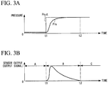
FIG. 3A is a diagram showing an example of pressure output in the pressure sensor shown inFIG. 1 . -
FIG. 3B is a diagram showing an example of sensor output in the pressure sensor shown inFIG. 1 . -
FIG. 4A is a diagram showing an example of the operation of the pressure sensor shown inFIG. 1 in a period A shown inFIG. 3A . -
FIG. 4B is a diagram showing an example of the operation of the pressure sensor shown inFIG. 1 in a period B shown inFIG. 3A . -
FIG. 4C is a diagram showing an example of the operation of the pressure sensor shown inFIG. 1 in a period C shown inFIG. 3A . -
FIG. 5A is a diagram showing the relationship among an outside gas pressure, an inside gas pressure, and a differential pressure between the outside gas pressure and the inside gas pressure in the pressure sensor shown inFIG. 1 when the frequency of the outside gas pressure Pout is 0.1 Hz. -
FIG. 5B is a diagram showing the relationship among an outside gas pressure, an inside gas pressure, and a differential pressure between the outside gas pressure and the inside gas pressure in the pressure sensor shown inFIG. 1 when the frequency of the outside gas pressure Pout is 0.5 Hz. -
FIG. 5C is a diagram showing the relationship among an outside gas pressure, an inside gas pressure, and a differential pressure between the outside gas pressure and the inside gas pressure in the pressure sensor shown inFIG. 1 when the frequency of the outside gas pressure Pout is 1 Hz. -
FIG. 6A is a diagram showing the relationship between the frequency of the outside gas pressure Pout and the differential pressure (the difference between the outside gas pressure Pout and the inside gas pressure Pin) inVerification Test 1 using the pressure sensor shown inFIG. 1 . -
FIG. 6B is a diagram showing the relationship between the frequency of the outside gas pressure Pout and the phase difference inVerification Test 1 using the pressure sensor shown inFIG. 1 . -
FIG. 7A is a diagram showing the relationship between the frequency of the outside gas pressure Pout and the differential pressure (the difference between the outside gas pressure Pout and the inside gas pressure Pin) inVerification Test 2 using the pressure sensor shown inFIG. 1 . -
FIG. 7B is a diagram showing the relationship between the frequency of the outside gas pressure Pout and the phase difference inVerification Test 2 using the pressure sensor shown inFIG. 1 . -
FIG. 8A is a diagram showing the relationship between the frequency of the outside gas pressure Pout and the differential pressure (the difference between the outside gas pressure Pout and the inside gas pressure Pin) inVerification Test 3 using the pressure sensor shown inFIG. 1 . -
FIG. 8B is a diagram showing the relationship between the frequency of the outside gas pressure Pout and the phase difference inVerification Test 3 using the pressure sensor shown inFIG. 1 . -
FIG. 9A is a diagram showing the relationship between the frequency of the outside gas pressure Pout and the differential pressure (the difference between the outside gas pressure Pout and the inside gas pressure Pin) inVerification Test 4 using the pressure sensor shown inFIG. 1 . -
FIG. 9B is a diagram showing the relationship between the frequency of the outside gas pressure Pout and the phase difference inVerification Test 4 using the pressure sensor shown inFIG. 1 . -
FIG. 10A is a diagram showing the relationship between the frequency of the outside gas pressure Pout and the differential pressure (the difference between the outside gas pressure Pout and the inside gas pressure Pin) inVerification Test 5 using the pressure sensor shown inFIG. 1 . -
FIG. 10B is a diagram showing the relationship between the frequency of the outside gas pressure Pout and the phase difference inVerification Test 5 using the pressure sensor shown inFIG. 1 . -
FIG. 11A is a diagram showing the relationship between the frequency of the outside gas pressure Pout and the differential pressure (the difference between the outside gas pressure Pout and the inside gas pressure Pin) in Verification Test 6 using the pressure sensor shown inFIG. 1 . -
FIG. 11B is a diagram showing the relationship between the frequency of the outside gas pressure Pout and the phase difference in Verification Test 6 using the pressure sensor shown inFIG. 1 . -
FIG. 12A is a diagram showing the relationship between the frequency of the outside gas pressure Pout and the differential pressure (the difference between the outside gas pressure Pout and the inside gas pressure Pin) in Verification Test 7 using the pressure sensor shown inFIG. 1 . -
FIG. 12B is a diagram showing the relationship between the frequency of the outside gas pressure Pout and the phase difference in Verification Test 7 using the pressure sensor shown inFIG. 1 . -
FIG. 13A is a diagram showing the relationship between the frequency of the outside gas pressure Pout and the differential pressure (the difference between the outside gas pressure Pout and the inside gas pressure Pin) in Verification Test 8 using the pressure sensor shown inFIG. 1 . -
FIG. 13B is a diagram showing the relationship between the frequency of the outside gas pressure Pout and the phase difference in Verification Test 8 using the pressure sensor shown inFIG. 1 . -
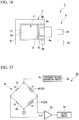
FIG. 14 is a plan view showing a pressure sensor according to an embodiment of the invention. -
FIG. 15 is a configuration diagram showing a detection circuit shown inFIG. 14 . - Hereinafter, a pressure sensor will be described referring to the drawings.
- As shown in
FIGS. 1 and 2 , apressure sensor 1 of this example detects pressure fluctuation in a predetermined frequency band, is formed of, for example, aSOI substrate 2, in which asilicon support layer 2a, anoxidized layer 2b, such as a silicon oxide film, and a siliconactive layer 2c are thermally bonded, and includes asensor body 3, acantilever 4, and adisplacement measurement unit 5. - The
sensor body 3 is formed in a bottomed tubular shape with an opening toward the upper side by thesilicon support layer 2a and the oxidizedlayer 2b in theSOI substrate 2. The internal space of thesensor body 3 is a cavity (air chamber) 10. A portion of the opening toward the upper side of thesensor body 3 is a communicating opening 11 (the upper side of the cavity 10) which communicates the inside and the outside of thecavity 10. That is, the top surface (first surface 3b) of thesensor body 3 has the communicatingopening 11 which communicates the inside and the outside of thecavity 10. - In the example shown in the drawing, although the
sensor body 3 is formed in a rectangular shape in plan view, thesensor body 3 is not limited to this shape. - The
cantilever 4 has abase end portion 4a and adistal end portion 4b as a free end, is formed in a plate shape extending in one direction from thebase end portion 4a to thedistal end portion 4b along the longitudinal direction of thesensor body 3, and is provided inside the communicatingopening 11 in a state where thebase end portion 4a is cantilevered by thesensor body 3. - Specifically, the
cantilever 4 is formed from, for example, the siliconactive layer 2c in theSOI substrate 2, and is integrally fixed to thefirst surface 3b in thebase end portion 4a and is thus cantilevered by thesensor body 3. Thecantilever 4 cantilevered by thesensor body 3 has a rectangular shape in plan view, is close to the opening end of the communicatingopening 11, and substantially closes the communicatingopening 11. With this, thecantilever 4 can be flexurally deformed with thebase end portion 4a as a base point according to the pressure difference between the inside and the outside of thecavity 10. - A
frame portion 12 which is formed from the siliconactive layer 2c in theSOI substrate 2 is fixed integrally to the top surface of a portion, to which thebase end portion 4a is not fixed, in aperipheral wall portion 3a of thesensor body 3. Agap 13 having a width G is formed in a U shape in plan view along the outer peripheral edge of thecantilever 4 between the outer peripheral edge of thecantilever 4 and a peripheral edge 11a of the communicating opening 11 (between thedistal end portion 4b and the peripheral edge 11a). - In the example shown in the drawing, although the
gap 13 is formed such that both the width of the gap in the longitudinal direction of thesensor body 3 and the width of the gap in the lateral direction of thesensor body 3 are the same width G, for example, thegap 13 may be formed such that the width of the gap in the longitudinal direction of thesensor body 3 is different from the width of the gap in the lateral direction of thesensor body 3. Thegap 13 may be formed such that the width of the gap appropriately changes. - In this case, Expression (1) may be used with the width of the gap with the largest width as the width G.
- The
base end portion 4a of thecantilever 4 has a through-hole 15 which is formed in a U shape in plan view, and is designed such that thecantilever 4 is easily flexurally deformed. However, the shape of the through-hole 15 is not limited to the above-described shape. The through-hole 15 may not be provided optionally. - The
base end portion 4a of thecantilever 4 has a pair ofpiezoresistors 20 which is formed with the through-hole 15 interposed therebetween in the lateral direction of thesensor body 3. Resistance values detected from thepiezoresistors 20 change depending on the flexure amount (displacement amount) of thecantilever 4. Awiring 21 formed of a conductive material is connected to therespective piezoresistors 20, and the overall shape including thewiring 21 and thepiezoresistors 20 is a U shape in plan view. Adetection circuit 22 which measures the displacement of thecantilever 4 based on the resistance values detected from thepiezoresistors 20 is connected to thepiezoresistors 20. - With this, when a predetermined voltage is applied to one
piezoresistor 20 through thedetection circuit 22, a current caused by the voltage application bypasses the through-hole 15 and flows from onepiezoresistor 20 to theother piezoresistor 20 through thewiring 21. - For this reason, the
detection circuit 22 can extract the resistance values, which change depending the displacement (flexural deformation) of thecantilever 4 and are detected from thepiezoresistors 20, as electrical output signals. Accordingly, the displacement of thecantilever 4 can be measured based on the output signals (sensor output), and the pressure fluctuation can be detected. - The
piezoresistors 20 are formed by doping a dopant (impurity), such as phosphorous, using various methods, such as an ion implantation method and a diffusion method. An insulating film (not shown) is coated as a protective film on the top surfaces of thepiezoresistors 20 and thewiring 21, and thus the piezoresistors 20 and thewiring 21 are prevented from coming into electrical contact with the outside. - The
piezoresistors 20, thewiring 21, and thedetection circuit 22 configure thedisplacement measurement unit 5 which measures the displacement of thecantilever 4. - Next, a case where pressure fluctuation is detected using the
pressure sensor 1 will be described. - First, as in a period A shown in
FIG. 3A , when the pressure difference between the pressure (hereinafter, referred to as an outside gas pressure Pout) outside thecavity 10 and the pressure (hereinafter, referred to as an inside gas pressure Pin) inside thecavity 10 is zero, as shown inFIG. 4A , thecantilever 4 is not flexurally deformed. - As shown in a period B after the time t1 in
FIG. 3A , for example, when the outside gas pressure Pout increases in a stepwise manner, a pressure difference is generated between the outside and the inside of thecavity 10. Accordingly, as shown inFIG. 4B , thecantilever 4 is flexurally deformed inward of thecavity 10. - Then, strain is generated in the
piezoresistors 20 according to the flexural deformation of thecantilever 4, and as the resistance values change, as shown inFIG. 3B , the output signals increase. - After the outside gas pressure Pout increases, a pressure transmission medium flows from the outside to the inside of the
cavity 10 through thegap 13. For this reason, as shown inFIG. 3A , the inside gas pressure Pin is later than the outside gas pressure Pout over time, and increases more gently than fluctuation in the outside gas pressure Pout. - With this, since the inside gas pressure Pin gradually becomes close to the outside gas pressure Pout, the pressure outside the
cavity 10 and the pressure inside thecavity 10 starts to reach equilibrium. Accordingly, the flexure of thecantilever 4 gradually becomes small, and as shown inFIG. 3B , the output signals gradually decreases. - As shown in a period C after the time t2 in
FIG. 3A , when the inside gas pressure Pin becomes equal to the outside gas pressure Pout, as shown inFIG. 4C , the flexural deformation of thecantilever 4 is eliminated and returns to the original state, and as shown inFIG. 3B , the output signals become zero again. - In this way, pressure fluctuation can be detected by monitoring fluctuation in the output signals based on the displacement of the
cantilever 4. - In particular, since the
cantilever 4 can be formed using the siliconactive layer 2c of theSOI substrate 2 by a semiconductor process technique, reduction in thickness (for example, tens or hundreds of nm) is easily achieved compared to a piezoelectric element of the related art. Therefore, it is possible to detect minute pressure fluctuation with high precision. - The
pressure sensor 1 of this example can be applied to various purposes described below. - For example, the pressure sensor can be applied to a navigation device for a vehicle. In this case, for example, a gas pressure difference can be detected based on a difference in height using the
pressure sensor 1. For this reason, accurate discrimination between an elevated road and a road under an elevated road can be reflected in a navigation result. - The pressure sensor can also be applied to a portable navigation device. In this case, for example, a gas pressure difference can be detected based on a difference in height using the
pressure sensor 1. For this reason, accurate discrimination regarding what floor the user is on can be reflected in a navigation result. - Furthermore, the pressure sensor can detect change in indoor gas pressure. For this reason, for example, the pressure sensor can also be applied to security devices of buildings and vehicles.
- In this way, although the
pressure sensor 1 can be applied to various purposes, in thepressure sensor 1 of this embodiment, the frequency band (Hz) of pressure fluctuation to be detected can be set in advance depending on the purpose of thepressure sensor 1. This point will be described below in detail. - First, an upper limit frequency can be set to the maximum resonance frequency of the
cantilever 4. For this reason, for example, it is possible to set the upper limit frequency to a desired value by appropriately changing vibration characteristics with the size, material, thickness, and the like of thecantilever 4. - Next, the setting of a lower limit frequency will be described.
- First, when the width G of the
gap 13 is large, since the pressure difference between the inside and the outside of thecavity 10 is rarely generated, the lower limit frequency of pressure fluctuation tends to increase. When the width G of thegap 13 is small, since the pressure difference between the inside and the outside of thecavity 10 is easily maintained, even minute pressure fluctuation is easily detected, and the lower limit frequency of pressure fluctuation tends to decrease. - When the volume V of the
cavity 10 is small, similarly to when the width G of thegap 13 is large, since the pressure difference between the inside and the outside of thecavity 10 is rarely generated, the lower limit frequency of pressure fluctuation tends to increase. When the volume V of thecavity 10 is large, similarly to when the width G of thegap 13 is small, since the pressure difference between the inside and the outside of thecavity 10 is easily maintained, the lower limit frequency of pressure fluctuation tends to decrease. - The inventors have further studied the general relationship among the lower limit frequency, the width G of the
gap 13, and the volume of thecavity 10, and have found that the relationship among the lower limit frequency, the width G of thegap 13, and the volume V of thecavity 10 satisfies the relational expression of Expression (1).

- In the expression, G is the width (µm) of the
gap 13, and V is the volume (ml) of thecavity 10. Furthermore, k is a proportional constant and is selected in a range of, for example, 0.005 to 0.02. - With this, simple design of only changing the values of the width G of the
gap 13 and the volume V of thecavity 10 allows the setting of the lower limit frequency of pressure fluctuation to be detected, which is difficult in the pressure sensor of the related art, to a desired value. - Therefore, it is possible to obtain a high-
quality pressure sensor 1 which can freely set both the upper limit frequency and the lower limit frequency, can arbitrarily set the frequency band of pressure fluctuation to be detected, and can broadly cope with various purposes, and easily exhibits optimum performance. - Hereinafter, the grounds for Expression (1) will be described along with the results of verification tests.
- First, as described above, as will be apparent from
FIGS. 3A and 3B , the flexural deformation of thecantilever 4 when pressure fluctuation is generated is in proportion to the difference (differential pressure) between the outside gas pressure Pout and the inside gas pressure Pin. At this time, when fluctuation in the outside gas pressure Pout is late (the frequency is small), the flexural deformation of thecantilever 4 becomes small, and the phase of the flexural deformation of thecantilever 4 with respect to the outside gas pressure Pout is advanced, whereby the phase difference from the flexural deformation of thecantilever 4 and the outside gas pressure Pout become large. -
FIGS. 5A to 5C show the relationship among the outside gas pressure Pout, the inside gas pressure Pin, and (the outside gas pressure Pout - the inside gas pressure Pin) when the frequency of the outside gas pressure Pout changes. - As shown in
FIGS. 5A to 5C , it is apparently recognized that the phase difference is smallest when the frequency of the outside gas pressure Pout is 1 Hz, and increases as the frequency of the outside gas pressure Pout decreases to 0.5 Hz and 0.1 Hz. This is commonly recognized regardless of the values of the width G of thegap 13 and the volume V of thecavity 10. - Next, the verification test result when the values of the width G of the
gap 13 and the volume V of thecavity 10 change will be described referring toFIGS. 6A to 13B . - Specifically, the relationship between the outside gas pressure Pout and the differential pressure (sensor output) between the outside gas pressure Pout and the inside gas pressure Pin when the values of the width G of the
gap 13 and the volume V of thecavity 10 change will be verified. -
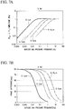
FIGS. 6A ,7A ,8A ,9A ,10A ,11A ,12A , and13A are diagrams showing the amplitude of the differential pressure between the outside gas pressure Pout and the inside gas pressure Pin when the frequency of the outside gas pressure Pout changes, andFIGS. 6B ,7B ,8B ,9B ,10B ,11B ,12B , and13B are diagrams showing the phase difference when the frequency of the outside gas pressure Pout changes. - A verification test was performed for four pressure sensors in which the volume V of the
cavity 10 was set to 0.5 ml and the widths G of thegap 13 was set to respective 1 µm, 3 µm, 5 µm, and 10 µm. At this time, the outside gas pressure Pout fluctuated periodically at 1.2 pa. The pressure sensors have the same configuration as thepressure sensor 1 of the above-described embodiment, except that the width G of thegap 13 is different. - As a result, as shown in
FIG. 6A , when the width G of thegap 13 was small, it could be confirmed that the lower limit frequency of pressure fluctuation in the outside gas pressure Pout to be detected actually decreased. As shown inFIG. 6B , it could be confirmed that, in case of a specific phase difference, the lower limit frequency of pressure fluctuation in the outside gas pressure Pout was substantially proportional to the square of the width G of thegap 13. - Specifically, as shown in
FIG. 6B , for example, it is recognized that the lower limit frequency of a phase difference of 45 deg when the width G of thegap 13 is 10 µm is approximately 100 times the lower limit frequency of the phase difference of 45 deg when the width G of thegap 13 is 1 µm. Furthermore, it is recognized that the lower limit frequency of the phase difference of 45 deg when the width G of thegap 13 is 10 µm is approximately four times the lower limit frequency of the phase difference of 45 deg when the width G of thegap 13 is 5 µm. - Next, a verification test was performed for four pressure sensors in which the volume V of the
cavity 10 was set to 1 ml and the widths G of thegap 13 was set to respective 1 µm, 3 µm, 5 µm, and 10 µm. As a result, as shown inFIGS. 7A and 7B , in this case, the same effects as inVerification Test 1 could be obtained. - Next, a verification test was performed for four pressure sensors in which the volume V of the
cavity 10 was set to 2 ml and the widths G of thegap 13 was set to respective 1 µm, 3 µm, 5 µm, and 10 µm. As a result, as shown inFIGS. 8A and 8B , in this case, the same effects as inVerification Test 1 could be obtained. - Next, a verification test was performed for four pressure sensors in which the volume V of the
cavity 10 was set to 4 ml and the widths G of thegap 13 was set to respective 1 µm, 3 µm, 5 µm, and 10 µm. As a result, as shown inFIGS. 9A and 9B , in this case, the same effects as inVerification Test 1 could be obtained. - Next, a verification test was performed for four pressure sensors in which the width G of the
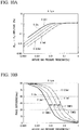
gap 13 was set to 1 µm and the volumes V of thecavity 10 was set to respective 0.5 ml, 1 ml, 2 ml, and 4 ml. At this time, the outside gas pressure Pout fluctuated periodically at 1.2 pa. Thepressure sensors 1 have the same configuration as thepressure sensor 1 of the above-described embodiment, except that the width G of thegap 13 is different. - As a result, as shown in
FIG. 10A , when the volume V of thecavity 10 was large, it could be confirmed that the lower limit frequency of pressure fluctuation in the outside gas pressure Pout to be detected actually decreased. As shown inFIG. 10B , it could be confirmed that, in case of a specific phase difference, the lower limit frequency of pressure fluctuation in the gas pressure Pout was in substantially inverse proportion to the volume V of thecavity 10. - Specifically, as shown in
FIG. 10B , for example, it is recognized that the lower limit frequency of the phase difference of 45 deg increases by approximately two times as the volume V of thecavity 10 decreases in an order of 4 ml, 2 ml, 1 ml, and 0.5 ml. - Next, a verification test was performed for four pressure sensors in which the width G of the
gap 13 was set to 3 µm and the volumes V of thecavity 10 was set to respective 0.5 ml, 1 ml, 2 ml, and 4 ml. As a result, as shown inFIGS. 11A and 11B , in this case, the same effects as inVerification Test 5 could be obtained. - Next, a verification test was performed for four pressure sensors in which the width G of the
gap 13 was set to 5 µm and the volumes V of thecavity 10 was set to respective 0.5 ml, 1 ml, 2 ml, and 4 ml. As a result, as shown inFIGS. 12A and 12B , in this case, the same effects as inVerification Test 5 could be obtained. - Next, a verification test was performed for four pressure sensors in which the width G of the
gap 13 was set to 10 µm and the volumes V of thecavity 10 was set to respective 0.5 ml, 1 ml, 2 ml, and 4 ml. As a result, as shown inFIGS. 13A and 13B , in this case, the same effects as inVerification Test 5 could be obtained. - From the results of the verification tests, it was recognized that, in case of a specific phase difference, the lower limit frequency of pressure fluctuation is in proportion to the square of the width G of the
gap 13 and is in inverse proportion to the volume V of thecavity 10. With this, Expression (1) could be found. - The proportional constant k is the correction value of the lower limit frequency, and is preferably selected in a range of 0.005 to 0.02. In particular, when the width G of the
gap 13 is in a range of 1 µm to 10 µm, and the volume V of thecavity 10 is in a range of 0.5 ml to 5 ml, it is easy to set the lower limit frequency to a desired value more accurately. - In the above-described example it is preferable that the lower limit frequency of pressure fluctuation be set based on Expression (2).

- In the expression, fnoise is a noise frequency (Hz).
- With this, it is possible to set the lower limit frequency of pressure fluctuation to be higher than a frequency for noise cutting. For this reason, for example, it is possible to obtain a pressure sensor which is rarely affected by atmospheric pressure fluctuation, and to further increase a value as a pressure sensor.
- In the above-described example although a system in which the displacement of the
cantilever 4 is measured using thepiezoresistors 20 has been used, for example, a system (a so-called optical lever system) in which detection light is irradiated onto thecantilever 4, and the displacement of thecantilever 4 is measured based on the light receiving position of reflected light from thecantilever 4 may be used. - However, in the above-described example the
cantilever 4 can become a self-displacement detection cantilever with the use of thepiezoresistor 20. For this reason, it is easy to perform pressure fluctuation detection with high precision without being affected by external light or the like. - In the embodiment, as shown in
FIG. 14 , areference cantilever 30 is further provided, and thedetection circuit 22 detects the difference between the output of thecantilever 4 and the output of thereference cantilever 30. - The
reference cantilever 30 has the same configuration as thecantilever 4, and for example, is integrally cantilevered by thesensor body 3 and fixed. However, thereference cantilever 30 is opened to outside gas and is not flexurally deformed due to pressure fluctuation in the outside gas pressure Pout. - In this case, for example, as shown in
FIG. 15 , thedetection circuit 22 includes a bridge circuit 31 (wheatstone bridge circuit), a referencevoltage generation circuit 32, anoperation amplifier circuit 33, and anoutput circuit 34. - In the
bridge circuit 31, a branch wire, on which the piezoresistor 20 [hereinafter, referred to as a first piezoresistor 40 (resistance value Rl)] of thecantilever 4 and the piezoresistor [hereinafter, referred to as a second piezoresistor 41 (resistance value R2)] of thereference cantilever 30 are connected in series, and a branch wire, on which a fixed resistor 42 (resistance value R3) and a fixed resistor 43 (resistance value R4) are connected in series, are connected in parallel with the referencevoltage generation circuit 32. - In the
bridge circuit 31, the connection point of thefirst piezoresistor 40 and thesecond piezoresistor 41 is connected to the inverting input terminal of theoperation amplifier circuit 33, and the connection point of the fixedresistor 42 and the fixedresistor 43 is connected to the non-inverting input terminal of theoperation amplifier circuit 33. - The reference
voltage generation circuit 32 applies a predetermined reference voltage Vcc to thebridge circuit 31. Theoperation amplifier circuit 33 detects the potential difference between the connection point of the two fixedresistors bridge circuit 31 and the connection point of thefirst piezoresistor 40 and thesecond piezoresistor 41, amplifies the potential difference with a predetermined amplification factor, and outputs the amplified potential difference. - The potential difference is the value according to the difference (R1 - R2) between the resistance value of the
first piezoresistor 40 and the resistance value of thesecond piezoresistor 41, that is, the difference between the output of thecantilever 4 and the output of thereference cantilever 30. - With the
detection circuit 22 configured as above, it is possible to cancel the output fluctuation amount (noise amount) due to environmental change such as change in temperature, and disturbance such as vibration, and to extract only the output signal according to pressure fluctuation of the outside gas pressure Pout. Therefore, it is possible to detect pressure fluctuation in a desired frequency band with higher precision. -
- 1
- pressure sensor
- 3
- sensor body
- 3a
- peripheral wall portion
- 3b
- first surface
- 4
- cantilever
- 4a
- base end portion of cantilever
- 4b
- distal end portion of cantilever
- 5
- displacement measurement unit
- 10
- cavity (air chamber)
- 11
- communicating opening
- 11a
- peripheral edge of communicating opening
- 13
- gap
- 20
- piezoresistor
Claims (5)
- A pressure sensor (1), comprising:a sensor body (3) which has a first surface (3b) and a cavity (10) with an opening (11) in the first surface (3b);a cantilever (4) which has a base end portion (4a) supported on the first surface (3b) and a distal end portion (4b) provided to form a gap (13) from a peripheral edge (11a) of the opening (11) inside the opening (11), the cantilever (4) being flexurally deformed according to a pressure difference between an inside and an outside of the cavity (10), the cantilever (4) being formed of a semiconductor material; anda displacement measurement unit (5) configured to measure a displacement of the cantilever (4) vibrating according to the pressure difference,characterized in that the pressure sensor (1) is configured to detect pressure fluctuations at a lower limit frequency fLOW defined by
 wherein a proportional constant is represented by k and k is in a range of 0.005 to 0.02 ×10⁶m/s, a width of the gap (13) is represented by G, and a volume of the cavity (10) is represented by V,the displacement measurement unit (5) includes a reference cantilever (30) and a detection circuit (22),the detection circuit (22) detects a difference between an output of the cantilever (4) and an output of the reference cantilever (30), and whereinthe reference cantilever (30) has the same configuration as the cantilever (4), and is integrally cantilevered by the sensor body (3) and fixed so as to be opened to gas outside of the cavity (10) but not flexurally deformed by the pressure fluctuation in the outside gas pressure (Pout).
 - The pressure sensor (1) according to Claim 1,
wherein the displacement measurement unit (5) is configured to measure the displacement of the cantilever (4) vibrating according to the pressure difference at a frequency larger than said lower limit frequency FLOW, wherein fLOW is larger than a noise frequency fnoise. - The pressure sensor (1) according to Claim 1 or 2,
wherein the displacement measurement unit (5) has a piezoresistor (20) formed in the base end portion (4a). - The pressure sensor (1) according to any one of Claims 1 to 3,
wherein the width of the gap (13) is in a range of 1 µm to 10 µm, and the volume of the cavity (10) is in a range of 0.5 ml to 5 ml. - The pressure sensor (1) according to any one of Claims 1 to 4,
wherein the base end portion (4a) is provided inside the opening (11) in a state where the base end portion (4a) is cantilevered by the sensor body (3).
Applications Claiming Priority (2)
| Application Number | Priority Date | Filing Date | Title |
|---|---|---|---|
| JP2012105306A JP5778619B2 (en) | 2012-05-02 | 2012-05-02 | Pressure sensor |
| PCT/JP2013/057765 WO2013164927A1 (en) | 2012-05-02 | 2013-03-19 | Pressure sensor |
Publications (3)
| Publication Number | Publication Date |
|---|---|
| EP2846143A1 EP2846143A1 (en) | 2015-03-11 |
| EP2846143A4 EP2846143A4 (en) | 2015-11-11 |
| EP2846143B1 true EP2846143B1 (en) | 2021-07-28 |
Family
ID=49514328
Family Applications (1)
| Application Number | Title | Priority Date | Filing Date |
|---|---|---|---|
| EP13785081.4A Active EP2846143B1 (en) | 2012-05-02 | 2013-03-19 | Pressure sensor |
Country Status (5)
| Country | Link |
|---|---|
| US (1) | US9551621B2 (en) |
| EP (1) | EP2846143B1 (en) |
| JP (1) | JP5778619B2 (en) |
| CN (1) | CN104272074B (en) |
| WO (1) | WO2013164927A1 (en) |
Families Citing this family (27)
| Publication number | Priority date | Publication date | Assignee | Title |
|---|---|---|---|---|
| US10817096B2 (en) | 2014-02-06 | 2020-10-27 | Apple Inc. | Force sensor incorporated into display |
| EP2954392B1 (en) | 2013-02-08 | 2022-12-28 | Apple Inc. | Force determination based on capacitive sensing |
| US9671889B1 (en) | 2013-07-25 | 2017-06-06 | Apple Inc. | Input member with capacitive sensor |
| JP6294083B2 (en) * | 2014-01-09 | 2018-03-14 | セイコーインスツル株式会社 | Electronics |
| CN106416298B (en) | 2014-01-24 | 2019-05-28 | 国立大学法人东京大学 | Sensor |
| EP3072040B1 (en) | 2014-02-12 | 2021-12-29 | Apple Inc. | Force determination employing sheet sensor and capacitive array |
| WO2015137160A1 (en) * | 2014-03-13 | 2015-09-17 | セイコーインスツル株式会社 | Pressure sensor |
| JP6292932B2 (en) * | 2014-03-13 | 2018-03-14 | セイコーインスツル株式会社 | Pressure sensor |
| JP6440431B2 (en) * | 2014-03-26 | 2018-12-19 | セイコーインスツル株式会社 | In-vehicle device |
| JP5650360B1 (en) * | 2014-06-25 | 2015-01-07 | セイコーインスツル株式会社 | Pressure change measuring device and pressure change measuring method |
| US10451510B2 (en) * | 2014-09-24 | 2019-10-22 | Seiko Instruments Inc. | Pressure change measurement device, altitude measurement device, and pressure change measurement method |
| US9995642B2 (en) | 2014-10-06 | 2018-06-12 | The University Of Tokyo | Cantilever pressure sensor with division portions for dividing lever resistance and having piezoresistor element |
| JP6403007B2 (en) * | 2015-01-08 | 2018-10-10 | 国立大学法人 東京大学 | Pressure sensor |
| JP6474619B2 (en) * | 2015-01-15 | 2019-02-27 | 国立大学法人 東京大学 | Pressure measuring device and pressure measuring method |
| JP6521441B2 (en) * | 2015-06-26 | 2019-05-29 | 国立大学法人 東京大学 | Pressure sensor |
| JP6521442B2 (en) * | 2015-06-26 | 2019-05-29 | 国立大学法人 東京大学 | Pressure sensor |
| WO2017016316A1 (en) * | 2015-07-28 | 2017-02-02 | 纳智源科技(唐山)有限责任公司 | Electronic cigarette pneumatic sensor, airflow processing device and electronic cigarette |
| EP3353517B1 (en) * | 2015-09-21 | 2020-03-04 | Opsens Solutions Inc. | Optical pressure sensor with reduced mechanical stresses |
| JP6073512B1 (en) * | 2016-03-10 | 2017-02-01 | 株式会社フジクラ | Differential pressure detection element, flow rate measuring device, and differential pressure detection element manufacturing method |
| US10007343B2 (en) * | 2016-03-31 | 2018-06-26 | Apple Inc. | Force sensor in an input device |
| JP6652479B2 (en) * | 2016-10-14 | 2020-02-26 | 株式会社フジクラ | Differential pressure detecting element and flow rate measuring device |
| JP7199187B2 (en) * | 2018-09-27 | 2023-01-05 | セイコーインスツル株式会社 | pulse wave sensor |
| JP7166120B2 (en) * | 2018-09-27 | 2022-11-07 | セイコーインスツル株式会社 | Pulse wave sensor and pulse wave measuring method |
| JP7178229B2 (en) * | 2018-09-27 | 2022-11-25 | セイコーインスツル株式会社 | pulse wave sensor |
| JP7130517B2 (en) * | 2018-09-28 | 2022-09-05 | セイコーインスツル株式会社 | Pulse wave sensor and vibration sensor |
| JP7156969B2 (en) * | 2019-02-21 | 2022-10-19 | セイコーインスツル株式会社 | Pressure sensor driving method |
| JP7410707B2 (en) * | 2019-12-23 | 2024-01-10 | セイコーインスツル株式会社 | Flow sensing devices and pump systems |
Family Cites Families (15)
| Publication number | Priority date | Publication date | Assignee | Title |
|---|---|---|---|---|
| DE68926601T2 (en) * | 1988-09-02 | 1997-01-23 | Honda Motor Co Ltd | Semiconductor sensor |
| US5079958A (en) * | 1989-03-17 | 1992-01-14 | Olympus Optical Co., Ltd. | Sensor having a cantilever |
| JPH071215B2 (en) * | 1990-10-31 | 1995-01-11 | 住友金属鉱山株式会社 | Air pressure change detector |
| JP2800112B2 (en) * | 1996-02-28 | 1998-09-21 | 株式会社エスアイアイ・アールディセンター | Semiconductor device |
| DE19648424C1 (en) | 1996-11-22 | 1998-06-25 | Siemens Ag | Micromechanical sensor |
| CN1166933C (en) | 2002-12-17 | 2004-09-15 | 林江 | Horizontal polarized sound wave mode adopted resonance type quartz pressure sensor |
| US20050172717A1 (en) * | 2004-02-06 | 2005-08-11 | General Electric Company | Micromechanical device with thinned cantilever structure and related methods |
| DE102006024381B3 (en) * | 2006-05-24 | 2007-12-06 | Fraunhofer-Gesellschaft zur Förderung der angewandten Forschung e.V. | MEMS vacuum sensor based on the friction principle |
| JP4916006B2 (en) | 2007-02-28 | 2012-04-11 | 株式会社山武 | Pressure sensor |
| KR100908124B1 (en) * | 2007-07-09 | 2009-07-16 | 삼성전자주식회사 | Pressure sensor for measuring blood pressure and manufacturing method thereof |
| US8120232B2 (en) * | 2009-01-20 | 2012-02-21 | Palo Alto Research Center Incorporated | Sensors and actuators using piezo polymer layers |
| EP2309241B1 (en) * | 2009-10-07 | 2016-11-30 | ams international AG | MEMS pressure sensor |
| CN102297741B (en) * | 2010-06-25 | 2013-06-05 | 中国科学院电子学研究所 | Silicon resonant air pressure sensor based on Micro-Electro-Mechanical Systems |
| EP2669648A4 (en) | 2011-01-28 | 2017-03-01 | The University of Tokyo | Differential pressure sensor |
| JP5867821B2 (en) * | 2012-03-08 | 2016-02-24 | セイコーインスツル株式会社 | Pressure sensor |
-
2012
- 2012-05-02 JP JP2012105306A patent/JP5778619B2/en active Active
-
2013
- 2013-03-19 CN CN201380022589.9A patent/CN104272074B/en active Active
- 2013-03-19 EP EP13785081.4A patent/EP2846143B1/en active Active
- 2013-03-19 WO PCT/JP2013/057765 patent/WO2013164927A1/en active Application Filing
- 2013-03-19 US US14/394,647 patent/US9551621B2/en active Active
Non-Patent Citations (1)
| Title |
|---|
| LOFDAHL L ET AL: "SMALL SILICON BASED PRESSURE TRANSDUCERS FOR MEASUREMENTS IN TURBULENT BOUNDARY LAYERS", EXPERIMENTS IN FLUIDS, SPRINGER, HEIDELBERG, DE, vol. 17, no. 1/02, 1 June 1994 (1994-06-01), pages 24 - 31, XP000477227, ISSN: 0723-4864 * |
Also Published As
| Publication number | Publication date |
|---|---|
| JP5778619B2 (en) | 2015-09-16 |
| CN104272074B (en) | 2016-05-25 |
| US9551621B2 (en) | 2017-01-24 |
| CN104272074A (en) | 2015-01-07 |
| EP2846143A1 (en) | 2015-03-11 |
| WO2013164927A1 (en) | 2013-11-07 |
| EP2846143A4 (en) | 2015-11-11 |
| US20150096388A1 (en) | 2015-04-09 |
| JP2013234853A (en) | 2013-11-21 |
Similar Documents
| Publication | Publication Date | Title |
|---|---|---|
| EP2846143B1 (en) | Pressure sensor | |
| Takahashi et al. | Differential pressure sensor using a piezoresistive cantilever | |
| EP3199934B1 (en) | Pressure change measurement device, altitude measurement device, and pressure change measurement method | |
| KR100741520B1 (en) | Semiconductor pressure sensor having diaphragm | |
| EP3205993B1 (en) | Pressure sensor | |
| CN104535251B (en) | Temperature self-compensating method and measuring mode for double-resonator pressure sensor | |
| US10393608B2 (en) | Pressure change measuring apparatus and pressure change measuring method | |
| US8464571B1 (en) | Systems and methods for determining resonant frequency and quality factor of overdamped systems | |
| US6634113B1 (en) | Tilt sensor and method of forming such device | |
| CN101706345A (en) | Method for compensating for heat drift of sensibility of micro pressure sensor | |
| US8552514B2 (en) | Semiconductor physical quantity sensor | |
| Tang et al. | An electrothermally excited dual beams silicon resonant pressure sensor with temperature compensation | |
| JP2014235095A (en) | Pressure sensor | |
| US20080106275A1 (en) | Sensor and Method for Measuring a Variable Affecting a Capacitive Component | |
| JP6184006B2 (en) | Pressure sensor | |
| US7278322B1 (en) | Semiconductor based pressure sensor | |
| US20050066704A1 (en) | Method and device for the electrical zero balancing for a micromechanical component | |
| André et al. | Ultra-low-power SOI CMOS pressure sensor based on orthogonal PMOS gauges | |
| Wei et al. | A piezoresistive sensor for pressure monitoring at inkjet nozzle | |
| JP6403007B2 (en) | Pressure sensor | |
| Watanabe et al. | Fusion of cantilever and diaphragm pressure sensors according to frequency characteristics | |
| JP7156969B2 (en) | Pressure sensor driving method | |
| JP6815900B2 (en) | Pressure sensor | |
| JPH0786617A (en) | Semiconductor pressure sensor | |
| Jourdan et al. | Suspended piezoresistive silicon nanogauges bridge for mems transduction: Spurious signal rejection capability |
Legal Events
| Date | Code | Title | Description |
|---|---|---|---|
| PUAI | Public reference made under article 153(3) epc to a published international application that has entered the european phase |
Free format text: ORIGINAL CODE: 0009012 |
|
| 17P | Request for examination filed |
Effective date: 20141027 |
|
| AK | Designated contracting states |
Kind code of ref document: A1 Designated state(s): AL AT BE BG CH CY CZ DE DK EE ES FI FR GB GR HR HU IE IS IT LI LT LU LV MC MK MT NL NO PL PT RO RS SE SI SK SM TR |
|
| AX | Request for extension of the european patent |
Extension state: BA ME |
|
| DAX | Request for extension of the european patent (deleted) | ||
| RA4 | Supplementary search report drawn up and despatched (corrected) |
Effective date: 20151012 |
|
| RIC1 | Information provided on ipc code assigned before grant |
Ipc: G01L 1/16 20060101ALI20151006BHEP Ipc: G01L 9/00 20060101AFI20151006BHEP Ipc: H01L 29/84 20060101ALI20151006BHEP Ipc: G01L 1/10 20060101ALI20151006BHEP Ipc: G01L 13/06 20060101ALI20151006BHEP |
|
| STAA | Information on the status of an ep patent application or granted ep patent |
Free format text: STATUS: EXAMINATION IS IN PROGRESS |
|
| 17Q | First examination report despatched |
Effective date: 20191015 |
|
| STAA | Information on the status of an ep patent application or granted ep patent |
Free format text: STATUS: EXAMINATION IS IN PROGRESS |
|
| REG | Reference to a national code |
Ref country code: DE Ref legal event code: R079 Ref document number: 602013078545 Country of ref document: DE Free format text: PREVIOUS MAIN CLASS: G01L0009000000 Ipc: G01L0023040000 |
|
| GRAJ | Information related to disapproval of communication of intention to grant by the applicant or resumption of examination proceedings by the epo deleted |
Free format text: ORIGINAL CODE: EPIDOSDIGR1 |
|
| STAA | Information on the status of an ep patent application or granted ep patent |
Free format text: STATUS: GRANT OF PATENT IS INTENDED |
|
| GRAP | Despatch of communication of intention to grant a patent |
Free format text: ORIGINAL CODE: EPIDOSNIGR1 |
|
| RIC1 | Information provided on ipc code assigned before grant |
Ipc: G01L 9/00 20060101ALI20210329BHEP Ipc: G01L 13/06 20060101ALI20210329BHEP Ipc: G01L 23/04 20060101AFI20210329BHEP |
|
| INTG | Intention to grant announced |
Effective date: 20210416 |
|
| RIN1 | Information on inventor provided before grant (corrected) |
Inventor name: SHINOGI, MASATAKA Inventor name: OUMI, MANABU Inventor name: UCHIYAMA, TAKESHI Inventor name: SHINOHARA, YOKO Inventor name: NGUYEN, MINH-DUNG Inventor name: TAKAHASHI, HIDETOSHI Inventor name: MATSUMOTO, KIYOSHI Inventor name: SHIMOYAMA, ISAO |
|
| GRAS | Grant fee paid |
Free format text: ORIGINAL CODE: EPIDOSNIGR3 |
|
| GRAA | (expected) grant |
Free format text: ORIGINAL CODE: 0009210 |
|
| STAA | Information on the status of an ep patent application or granted ep patent |
Free format text: STATUS: THE PATENT HAS BEEN GRANTED |
|
| REG | Reference to a national code |
Ref country code: DE Ref legal event code: R082 Ref document number: 602013078545 Country of ref document: DE Representative=s name: HOFFMANN - EITLE PATENT- UND RECHTSANWAELTE PA, DE |
|
| AK | Designated contracting states |
Kind code of ref document: B1 Designated state(s): AL AT BE BG CH CY CZ DE DK EE ES FI FR GB GR HR HU IE IS IT LI LT LU LV MC MK MT NL NO PL PT RO RS SE SI SK SM TR |
|
| REG | Reference to a national code |
Ref country code: GB Ref legal event code: FG4D |
|
| REG | Reference to a national code |
Ref country code: CH Ref legal event code: EP |
|
| REG | Reference to a national code |
Ref country code: DE Ref legal event code: R096 Ref document number: 602013078545 Country of ref document: DE |
|
| REG | Reference to a national code |
Ref country code: AT Ref legal event code: REF Ref document number: 1415119 Country of ref document: AT Kind code of ref document: T Effective date: 20210815 |
|
| REG | Reference to a national code |
Ref country code: IE Ref legal event code: FG4D |
|
| REG | Reference to a national code |
Ref country code: LT Ref legal event code: MG9D |
|
| REG | Reference to a national code |
Ref country code: NL Ref legal event code: MP Effective date: 20210728 |
|
| REG | Reference to a national code |
Ref country code: AT Ref legal event code: MK05 Ref document number: 1415119 Country of ref document: AT Kind code of ref document: T Effective date: 20210728 |
|
| PG25 | Lapsed in a contracting state [announced via postgrant information from national office to epo] |
Ref country code: LT Free format text: LAPSE BECAUSE OF FAILURE TO SUBMIT A TRANSLATION OF THE DESCRIPTION OR TO PAY THE FEE WITHIN THE PRESCRIBED TIME-LIMIT Effective date: 20210728 Ref country code: AT Free format text: LAPSE BECAUSE OF FAILURE TO SUBMIT A TRANSLATION OF THE DESCRIPTION OR TO PAY THE FEE WITHIN THE PRESCRIBED TIME-LIMIT Effective date: 20210728 Ref country code: BG Free format text: LAPSE BECAUSE OF FAILURE TO SUBMIT A TRANSLATION OF THE DESCRIPTION OR TO PAY THE FEE WITHIN THE PRESCRIBED TIME-LIMIT Effective date: 20211028 Ref country code: RS Free format text: LAPSE BECAUSE OF FAILURE TO SUBMIT A TRANSLATION OF THE DESCRIPTION OR TO PAY THE FEE WITHIN THE PRESCRIBED TIME-LIMIT Effective date: 20210728 Ref country code: NO Free format text: LAPSE BECAUSE OF FAILURE TO SUBMIT A TRANSLATION OF THE DESCRIPTION OR TO PAY THE FEE WITHIN THE PRESCRIBED TIME-LIMIT Effective date: 20211028 Ref country code: PT Free format text: LAPSE BECAUSE OF FAILURE TO SUBMIT A TRANSLATION OF THE DESCRIPTION OR TO PAY THE FEE WITHIN THE PRESCRIBED TIME-LIMIT Effective date: 20211129 Ref country code: NL Free format text: LAPSE BECAUSE OF FAILURE TO SUBMIT A TRANSLATION OF THE DESCRIPTION OR TO PAY THE FEE WITHIN THE PRESCRIBED TIME-LIMIT Effective date: 20210728 Ref country code: ES Free format text: LAPSE BECAUSE OF FAILURE TO SUBMIT A TRANSLATION OF THE DESCRIPTION OR TO PAY THE FEE WITHIN THE PRESCRIBED TIME-LIMIT Effective date: 20210728 Ref country code: FI Free format text: LAPSE BECAUSE OF FAILURE TO SUBMIT A TRANSLATION OF THE DESCRIPTION OR TO PAY THE FEE WITHIN THE PRESCRIBED TIME-LIMIT Effective date: 20210728 Ref country code: SE Free format text: LAPSE BECAUSE OF FAILURE TO SUBMIT A TRANSLATION OF THE DESCRIPTION OR TO PAY THE FEE WITHIN THE PRESCRIBED TIME-LIMIT Effective date: 20210728 Ref country code: HR Free format text: LAPSE BECAUSE OF FAILURE TO SUBMIT A TRANSLATION OF THE DESCRIPTION OR TO PAY THE FEE WITHIN THE PRESCRIBED TIME-LIMIT Effective date: 20210728 |
|
| PG25 | Lapsed in a contracting state [announced via postgrant information from national office to epo] |
Ref country code: PL Free format text: LAPSE BECAUSE OF FAILURE TO SUBMIT A TRANSLATION OF THE DESCRIPTION OR TO PAY THE FEE WITHIN THE PRESCRIBED TIME-LIMIT Effective date: 20210728 Ref country code: LV Free format text: LAPSE BECAUSE OF FAILURE TO SUBMIT A TRANSLATION OF THE DESCRIPTION OR TO PAY THE FEE WITHIN THE PRESCRIBED TIME-LIMIT Effective date: 20210728 Ref country code: GR Free format text: LAPSE BECAUSE OF FAILURE TO SUBMIT A TRANSLATION OF THE DESCRIPTION OR TO PAY THE FEE WITHIN THE PRESCRIBED TIME-LIMIT Effective date: 20211029 |
|
| PG25 | Lapsed in a contracting state [announced via postgrant information from national office to epo] |
Ref country code: DK Free format text: LAPSE BECAUSE OF FAILURE TO SUBMIT A TRANSLATION OF THE DESCRIPTION OR TO PAY THE FEE WITHIN THE PRESCRIBED TIME-LIMIT Effective date: 20210728 |
|
| REG | Reference to a national code |
Ref country code: DE Ref legal event code: R097 Ref document number: 602013078545 Country of ref document: DE |
|
| PG25 | Lapsed in a contracting state [announced via postgrant information from national office to epo] |
Ref country code: SM Free format text: LAPSE BECAUSE OF FAILURE TO SUBMIT A TRANSLATION OF THE DESCRIPTION OR TO PAY THE FEE WITHIN THE PRESCRIBED TIME-LIMIT Effective date: 20210728 Ref country code: SK Free format text: LAPSE BECAUSE OF FAILURE TO SUBMIT A TRANSLATION OF THE DESCRIPTION OR TO PAY THE FEE WITHIN THE PRESCRIBED TIME-LIMIT Effective date: 20210728 Ref country code: RO Free format text: LAPSE BECAUSE OF FAILURE TO SUBMIT A TRANSLATION OF THE DESCRIPTION OR TO PAY THE FEE WITHIN THE PRESCRIBED TIME-LIMIT Effective date: 20210728 Ref country code: EE Free format text: LAPSE BECAUSE OF FAILURE TO SUBMIT A TRANSLATION OF THE DESCRIPTION OR TO PAY THE FEE WITHIN THE PRESCRIBED TIME-LIMIT Effective date: 20210728 Ref country code: CZ Free format text: LAPSE BECAUSE OF FAILURE TO SUBMIT A TRANSLATION OF THE DESCRIPTION OR TO PAY THE FEE WITHIN THE PRESCRIBED TIME-LIMIT Effective date: 20210728 Ref country code: AL Free format text: LAPSE BECAUSE OF FAILURE TO SUBMIT A TRANSLATION OF THE DESCRIPTION OR TO PAY THE FEE WITHIN THE PRESCRIBED TIME-LIMIT Effective date: 20210728 |
|
| PLBE | No opposition filed within time limit |
Free format text: ORIGINAL CODE: 0009261 |
|
| STAA | Information on the status of an ep patent application or granted ep patent |
Free format text: STATUS: NO OPPOSITION FILED WITHIN TIME LIMIT |
|
| 26N | No opposition filed |
Effective date: 20220429 |
|
| PG25 | Lapsed in a contracting state [announced via postgrant information from national office to epo] |
Ref country code: IT Free format text: LAPSE BECAUSE OF FAILURE TO SUBMIT A TRANSLATION OF THE DESCRIPTION OR TO PAY THE FEE WITHIN THE PRESCRIBED TIME-LIMIT Effective date: 20210728 |
|
| PG25 | Lapsed in a contracting state [announced via postgrant information from national office to epo] |
Ref country code: MC Free format text: LAPSE BECAUSE OF FAILURE TO SUBMIT A TRANSLATION OF THE DESCRIPTION OR TO PAY THE FEE WITHIN THE PRESCRIBED TIME-LIMIT Effective date: 20210728 |
|
| REG | Reference to a national code |
Ref country code: CH Ref legal event code: PL |
|
| REG | Reference to a national code |
Ref country code: BE Ref legal event code: MM Effective date: 20220331 |
|
| PG25 | Lapsed in a contracting state [announced via postgrant information from national office to epo] |
Ref country code: LU Free format text: LAPSE BECAUSE OF NON-PAYMENT OF DUE FEES Effective date: 20220319 Ref country code: LI Free format text: LAPSE BECAUSE OF NON-PAYMENT OF DUE FEES Effective date: 20220331 Ref country code: IE Free format text: LAPSE BECAUSE OF NON-PAYMENT OF DUE FEES Effective date: 20220319 Ref country code: CH Free format text: LAPSE BECAUSE OF NON-PAYMENT OF DUE FEES Effective date: 20220331 |
|
| PG25 | Lapsed in a contracting state [announced via postgrant information from national office to epo] |
Ref country code: BE Free format text: LAPSE BECAUSE OF NON-PAYMENT OF DUE FEES Effective date: 20220331 |
|
| PGFP | Annual fee paid to national office [announced via postgrant information from national office to epo] |
Ref country code: FR Payment date: 20230208 Year of fee payment: 11 |
|
| PGFP | Annual fee paid to national office [announced via postgrant information from national office to epo] |
Ref country code: GB Payment date: 20230202 Year of fee payment: 11 Ref country code: DE Payment date: 20230131 Year of fee payment: 11 |
|
| PG25 | Lapsed in a contracting state [announced via postgrant information from national office to epo] |
Ref country code: HU Free format text: LAPSE BECAUSE OF FAILURE TO SUBMIT A TRANSLATION OF THE DESCRIPTION OR TO PAY THE FEE WITHIN THE PRESCRIBED TIME-LIMIT; INVALID AB INITIO Effective date: 20130319 |