JP4385397B2 - Drain trap - Google Patents
Drain trap Download PDFInfo
- Publication number
- JP4385397B2 JP4385397B2 JP2003062869A JP2003062869A JP4385397B2 JP 4385397 B2 JP4385397 B2 JP 4385397B2 JP 2003062869 A JP2003062869 A JP 2003062869A JP 2003062869 A JP2003062869 A JP 2003062869A JP 4385397 B2 JP4385397 B2 JP 4385397B2
- Authority
- JP
- Japan
- Prior art keywords
- water
- silver
- electrode
- drain trap
- counter electrode
- Prior art date
- Legal status (The legal status is an assumption and is not a legal conclusion. Google has not performed a legal analysis and makes no representation as to the accuracy of the status listed.)
- Expired - Fee Related
Links
- XLYOFNOQVPJJNP-UHFFFAOYSA-N water Substances O XLYOFNOQVPJJNP-UHFFFAOYSA-N 0.000 claims description 262
- 229910052709 silver Inorganic materials 0.000 claims description 160
- 239000004332 silver Substances 0.000 claims description 160
- BQCADISMDOOEFD-UHFFFAOYSA-N Silver Chemical compound [Ag] BQCADISMDOOEFD-UHFFFAOYSA-N 0.000 claims description 125
- 238000007789 sealing Methods 0.000 claims description 16
- 229910052751 metal Inorganic materials 0.000 claims description 15
- 239000002184 metal Substances 0.000 claims description 15
- 238000004140 cleaning Methods 0.000 claims description 8
- -1 silver ions Chemical class 0.000 description 36
- 238000005406 washing Methods 0.000 description 12
- 238000010828 elution Methods 0.000 description 11
- 241000894006 Bacteria Species 0.000 description 10
- FOIXSVOLVBLSDH-UHFFFAOYSA-N Silver ion Chemical compound [Ag+] FOIXSVOLVBLSDH-UHFFFAOYSA-N 0.000 description 10
- 230000000694 effects Effects 0.000 description 9
- 230000001954 sterilising effect Effects 0.000 description 9
- 230000000844 anti-bacterial effect Effects 0.000 description 8
- BASFCYQUMIYNBI-UHFFFAOYSA-N platinum Chemical compound [Pt] BASFCYQUMIYNBI-UHFFFAOYSA-N 0.000 description 8
- 241000233866 Fungi Species 0.000 description 7
- 239000003814 drug Substances 0.000 description 7
- 238000000034 method Methods 0.000 description 7
- 239000011347 resin Substances 0.000 description 6
- 229920005989 resin Polymers 0.000 description 6
- 239000010408 film Substances 0.000 description 5
- PCHJSUWPFVWCPO-UHFFFAOYSA-N gold Chemical compound [Au] PCHJSUWPFVWCPO-UHFFFAOYSA-N 0.000 description 4
- 229910052737 gold Inorganic materials 0.000 description 4
- 239000010931 gold Substances 0.000 description 4
- 239000000463 material Substances 0.000 description 4
- 235000019645 odor Nutrition 0.000 description 4
- 239000005416 organic matter Substances 0.000 description 4
- 229910052697 platinum Inorganic materials 0.000 description 4
- 150000003839 salts Chemical class 0.000 description 4
- 239000000126 substance Substances 0.000 description 4
- 241001674044 Blattodea Species 0.000 description 3
- 229910021645 metal ion Inorganic materials 0.000 description 3
- 238000004659 sterilization and disinfection Methods 0.000 description 3
- 241000700159 Rattus Species 0.000 description 2
- 239000011248 coating agent Substances 0.000 description 2
- 238000000576 coating method Methods 0.000 description 2
- 239000000835 fiber Substances 0.000 description 2
- 239000004615 ingredient Substances 0.000 description 2
- 150000002739 metals Chemical class 0.000 description 2
- 238000002156 mixing Methods 0.000 description 2
- 238000003756 stirring Methods 0.000 description 2
- 239000002351 wastewater Substances 0.000 description 2
- 241000699670 Mus sp. Species 0.000 description 1
- 239000003242 anti bacterial agent Substances 0.000 description 1
- 229940121375 antifungal agent Drugs 0.000 description 1
- 239000003429 antifungal agent Substances 0.000 description 1
- 238000011109 contamination Methods 0.000 description 1
- 230000007423 decrease Effects 0.000 description 1
- 230000001877 deodorizing effect Effects 0.000 description 1
- 238000000151 deposition Methods 0.000 description 1
- 238000010586 diagram Methods 0.000 description 1
- 239000003657 drainage water Substances 0.000 description 1
- 229940079593 drug Drugs 0.000 description 1
- 238000001035 drying Methods 0.000 description 1
- 238000005868 electrolysis reaction Methods 0.000 description 1
- 238000005516 engineering process Methods 0.000 description 1
- 230000007613 environmental effect Effects 0.000 description 1
- WQYVRQLZKVEZGA-UHFFFAOYSA-N hypochlorite Inorganic materials Cl[O-] WQYVRQLZKVEZGA-UHFFFAOYSA-N 0.000 description 1
- 238000009434 installation Methods 0.000 description 1
- 238000005304 joining Methods 0.000 description 1
- 239000007788 liquid Substances 0.000 description 1
- 238000012423 maintenance Methods 0.000 description 1
- 230000000813 microbial effect Effects 0.000 description 1
- 150000002894 organic compounds Chemical class 0.000 description 1
- 239000010865 sewage Substances 0.000 description 1
- 239000000344 soap Substances 0.000 description 1
- 238000003860 storage Methods 0.000 description 1
- 239000010409 thin film Substances 0.000 description 1
Images


Landscapes
- Sink And Installation For Waste Water (AREA)
Description
【0001】
【発明の属する技術分野】
本発明は、殺菌性金属によりメンテナンスフリーでぬめりを防止することが可能な排水トラップに関するものである。
【0002】
【従来の技術】
通常排水トラップは水が常時溜まっている封水部と、水が流れる時のみ水が接触する壁面により構成されている。最初に水が流れる時のみ水が接触する壁面の汚れについて説明する。従来、排水トラップ壁面は有機物を多く含むお湯が接触するため、細菌が繁殖しやすく、また、常に水と接触しているわけではなく、適度に乾燥するため、かびの繁殖も多く見られた。そのような細菌やかび等の微生物汚れはぬめりの原因となったり、見た目にも汚れているといった悪い印象を与える問題があった。さらに、キッチンの排水トラップにおいては、その部分に排水かごが設置されており、その排水かごも同様に細菌が繁殖しやすい問題があった。
水が溜まる封水部は下水道からのゴキブリや、ねずみの進入を防止するため、水が常に存在し、人や石鹸などの有機物が多く存在しており、さらに水温が40℃程度のお湯が定常的に流れてくるため、細菌が繁殖しやすい環境となっている。そのため、封水部は細菌に由来するぬめりや、悪臭が発生する問題が多く生じている。このように封水部、壁面ともに排水トラップは菌やかび由来の汚れが多いにもかかわらず、そこに手を入れて掃除をするには抵抗が強く、掃除頻度が少なくなり、さらにぬめりや臭いが多くなり、より掃除を行うことに抵抗を感じるようになるといった悪循環となりやすい。
従来、有機化合物の金属塩よりなる抗菌、防カビ剤を含有する繊維状物質を排水トラップの上部に設置し、水が通過するときに金属イオンが水中に溶け込み、その金属イオンの効果により排水トラップのぬめりを防止する方法がある(例えば特許文献1参照)。また、排水トラップ上部に薬剤を収納する収納部設置し、薬剤の殺菌効果によりぬめりを防止する方法がある(例えば特許文献2参照)。
また、電気分解によって銀イオンや次亜塩素酸イオンを発生させて殺菌作用を持たせることは知られているが、排水トラップにおいて電源を用いることは適当であるとは言い難い。電源を用いない方法として、銀電極と、銀よりイオン化傾向の小さい金属を組み合わせて自己電池を形成し、銀イオンを放出させ、抗菌効果を持たせる技術が開示されている(例えば特許文献3参照)。
【0003】
【特許文献1】
特開2000−45352号公報
【特許文献2】
特開2001−65021号公報
【特許文献3】
特開平10−263054号公報
【発明が解決しようとする課題】
【0004】
しかし、特許文献1記載の方法においては、金属塩を含有した繊維は金属イオンを初期に大量に溶出し、含有された銀イオンが無くなってしまうため、徐々に放出量が少なくなり、そのため、初期は確かにぬめり防止効果があるが、新しいものと交換せずに使用していると銀イオンが不足するため、ぬめり防止効果がなくなり、交換が必要となる問題があり、このことは利用者が手間となるだけでなく、ランニングコストが高くなる問題があった。これはどんなに金属塩含有率を上げても、初期の溶出量が増加するだけで問題を解決することはできなかった。また、浴室、キッチンとも排水トラップ上部は水が勢いよく流れ込んだり、キッチンにおいては利用者が触ったり、食器や食材が当たるため、強度が必要であるが、金属塩を含有させた繊維は非常に強度が弱く、耐久性に問題があった。また、特許文献2に記載の方法においては薬剤を使用するため、薬剤収納部自体を交換、あるいは薬剤を収納部に投入することが随時必要となり、利用者に負荷がかかると同時にランニングコストが高くつく問題があった。また、薬剤を使用しているため、子供などが誤って口に入れた時に危険であったり、環境負荷がかかる問題があった。また、排水トラップの材料自体に銀を配合することも可能であるが、例えば樹脂などに全体に銀を分散させると数%レベルで銀を配合しても、材料表面よりも中心部に銀が固まってしまう問題があり、実際に殺菌に関与できる銀が少なくなってしまう。そのため、ほとんど銀イオンの溶出は見られず、殺菌効果を示すことはできなかった。また、銀イオンの溶出を上げるために銀含有率を上げると黒ずみがでてくるため、含有率には限界がある。
【0005】
一方、特許文献3記載の、自己電池を形成して銀イオンを放出させる技術を排水トラップに応用するには単に有機金属塩含有繊維や薬剤と置き換えるだけでは殺菌効果を発揮させるのは困難である。例えば洗い場で水をたらいに溜めて少しずつ利用する場合は流量が少なく、浴槽に溜めた水を一気に排水する場合には流量が非常に多く、流速も早くなる。そのため、銀とその対極を共に排水トラップの上部に設けても、どの部分に水が流れるかは、その時々に応じて異なるため、銀とその対極が両方同時に水と接触し、電流が流れるようにするという状況には必ずしもなるとは限らず、安定して十分な殺菌性を得ることはできなかった。また、浴槽水排水時も洗い場利用時も流速が一定でないため、流速が早い時には、水と銀電極の接触時間が短く、銀イオンを十分溶出させる時間がなく、濃度を高めることができなかった。
【0006】
そこで本発明は水溜まり部を設けることで、銀とその対極が確実に同一系において水と接触することが可能となり、さらに銀イオン濃度を高めることができ、電源が要らずに自己電池を形成し、殺菌性の銀イオンを安定的に供給でき、メンテナンスフリーで排水トラップ全体の殺菌を可能とし、細菌やかびの繁殖を抑制することができる排水トラップを提供する。
【0007】
【課題を解決するための手段および作用・効果】
上記課題を解決するためになされた本発明は、排水トラップであって、前記排水トラップの上部に水溜まり部を備え、前記水溜まり部は水出口を少なくとも1つ有し、前記水溜まり部は少なくとも表面の一部に銀電極を有し、前記銀電極は電気的に接合された対極を有し、前記対極は銀よりもイオン化傾向の小さい金属からなり、前記対極は、前記水溜まり部内に配置されたことを特徴とする。
【0008】
浴槽あるいは洗い場からの排水経路に銀電極を設けると水の流れは様々であるため、水の流れによっては、銀電極と対極が、水を通しての電子の授受が出来ず、自己電池を形成することができない。水溜まり部があることで、銀電極と対極が自己電池を構成することができる。確実に自己電池を構成できるよう、水出口は入口より小さくするなどして水がたまっている時間が長くなる構成が好ましい。
水溜まり部に溜まった水には徐々に銀イオンが溶出し、少しずつ排出され、排水トラップ壁面を流れ、封水部に達する。その際銀イオンの殺菌効果により、排水トラップの壁面のぬめりと封水部のぬめりを共に防止することができる。
この方式においては自己電池を利用しているため、電源が要らず、また、銀は微少濃度において殺菌効果が得られるため、水溜まり部に少量銀が配合されているだけで、薬剤のような取り替えや、メンテナンスが必要なくなる。なお、銀よりイオン化傾向の小さい金属の例としては、金や白金が挙げられる。また、水溜まり部は、なるべく上にあることが好ましいが、排水トラップの封水部の喫水面より上であればかまわない。
【0009】
また、本発明の一態様においては、水が貯留する封水部を有する排水トラップであって、前記排水トラップの上部に水溜まり部を設け、該水溜まり部は水出口を少なくとも1つ有し、前記水溜まり部は少なくとも表面の一部に銀電極を有し、前記銀電極は電気的に接合された対極を有し、前記対極は銀よりもイオン化傾向の小さい金属からなり、前記対極は、前記封水部内に配置されたことを特徴とする。
【0010】
水出口に汚れが詰まってしまっている時は水溜まり部に溜まった水に銀イオンを溶出させても、徐々に水溜まり部に溜まった水が排水されないため、排水トラップの殺菌効果がなく、無駄に銀イオンを溶出させてしまうことになる。そのため、封水部内に対極を設けることにより、水溜まり部の水が水出口から確実に排水されている時のみ、封水部内の水と、水溜まり部の水が同一系でつながるため、自己電池を形成することができ、無駄に銀イオンを溶出させることを防止することができる。
【0011】
また、本発明の一態様においては、水が貯留する封水部を有する排水トラップにおいて、該封水部は少なくとも表面の一部に銀電極を有し、前記銀電極は電気的に接合された対極を有し、さらに前記銀電極と対極は共に前記封水部内の水面より低い位置に設置され、前記対極は銀よりもイオン化傾向の小さい金属からなることを特徴とする。
【0012】
封水部全体あるいは一部を銀電極とすることで封水部近傍の銀イオン濃度が高くなり、より確実にトラップ壁面のぬめりを防止することができる。また、銀電極を洗浄することができ、銀電極が汚れて銀イオンの溶出が少なくなったりすることなく安定的に銀イオンを溶出させることが可能となる。
【0013】
また、本発明の好ましい態様においては、前記銀電極と対極は前記水溜まり部の最も下部に配置されたことを特徴とする。
【0014】
本態様においては、水溜まりから、すべての水が排水される直前まで、自己電池を形成し、銀イオンを溶出させることができる。
【0015】
また、本発明の好ましい態様においては、前記水入口にフィルターを設けたことを特徴とする。
【0016】
キッチンにおいては食材、浴室においては髪の毛などの洗い汚れが、水溜まり部に入り、水溜まり部に汚れが溜まったり、水出口が詰まることを防止することができる。
【0017】
また、本発明の好ましい態様においては、前記水出口は排水トラップ壁面にそって設けられていることを特徴とする。
【0018】
浴室においては、ぬめりやかびが問題となるのは壁面のみであるため、壁面側に出口を設けることにより、壁面を通らずに銀イオンを含有する水を無駄に落下させることを防止し、壁面に確実に銀イオンを含有する水を流すことができる。
【0019】
また、本発明の好ましい態様においては、前記水出口が最も下部になるように傾斜を成していることを特徴とする。
【0020】
本発明によれば、水溜まり部に溜まった、銀イオンを含有する水を確実に排水することで、銀イオン水をすべて有効利用することができる。
【0021】
また、本発明の好ましい態様においては、前記銀電極は、前記水溜り部を構成する部材に膜状にコーティングされていることを特徴とする。
また、本発明の好ましい態様においては、前記銀電極は、前記封水部を構成する部材に膜状にコーティングされていることを特徴とする。
【0022】
銀電極を例えば樹脂やゴム等にコーティングすることで、少ない銀量で銀同士が互いに電気的に接合されたまま水溜まり部全体に行き渡らせることができるため、銀イオンを含有する水を排水トラップ壁面全体に流すことができる。
【0023】
また、本発明の好ましい態様においては、前記対極は、前記銀電極に膜状にコーティングされていることを特徴とする。
【0024】
対極に白金あるいは金などを使用すると、高コストとなる問題がある。そこで銀電極に蒸着させることにより、薄い膜状に付着し、白金や金などの異なる金属の使用量を極少量にすることができる。
【0025】
【発明の実施の形態】
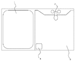
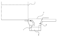
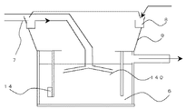
図1において、1は浴槽、2は水栓、3は洗い場、4は排水トラップである。図2は図1の断面図であり、5は排水トラップ蓋、6は水が常に溜まっている封水部、7は排水ホースである。図3は排水トラップ4の拡大断面図であり、8は水溜まり部、9は排水トラップ壁面、14は対極である。通常浴槽1の溜め水や、洗い場3で体や髪を洗う時に流れる水は排水トラップ4を通り、戸外へ排水される。また、排水トラップは、通常下水からのゴキブリや、ねずみの進入や、悪臭を防止するため、水が常に溜まるようにトラップ構造となっている。封水部6には常に水が溜まるような構成となっているため、下水道からのゴキブリや、ねずみの進入や、悪臭は、封水部の溜まり水により防止することができる。しかし、封水部の水が常に溜まっている部分は有機物が豊富に存在している、水が常に存在している、お湯が頻繁に流れてくる、という細菌が繁殖しやすい環境となっている。そのため、封水部では菌由来のぬめりが生じやすいという問題がある。また、排水トラップの壁面9も同様に細菌が繁殖しやすく、さらに適度に乾燥されることもあるため、水中では繁殖しにくいかびの繁殖も促進され、細菌、かびともに問題となってくる。
【0026】
本発明の第一の実施形態について添付図面を用いて詳細に説明する。図3において排水トラップ上部に水溜まり部8を設け、洗い場2あるいは浴槽1からの水溜まり部8を通り、大部分の水はオーバーフローすることで、封水部6に直接流れ込み排水されるが、排水終了時には一部の水は水溜まり部8に溜まる構成となっている。図示されていないが、水溜まり部8は銀電極を有している。水溜まり部全体が銀でできていても良いし、水溜まり部の一部が銀でできていて他は樹脂やゴムなどの別の材質で構成することも可能である。また、使用銀量を少なくするために、樹脂やゴムなど別の素材に銀が全体あるいは一部にコーティングされていたり、樹脂やゴム全体の表面に銀を網目状に配されていることがさらに好ましい。さらに銀電極には対極14が設けられている。この対極は銀と比較してイオン化傾向が低く、溶出しにくい金属である必要がある。具体的には白金あるいは金が挙げられる。銀電極は対極14と電気的に接合されている。電気的に接合されているとは電子の移動が起こるような接合ということで、銀電極と対極が直接接合されている、あるいは導電性の電線などによって接合されていることを指す。また、導電性の電線などによって接合する場合には、電線の溶出により銀イオンの溶出が阻害されることがないように、電線などを樹脂等でコーティングするのが望ましい。
このようにすることで、銀電極と対極の間で自己電池が形成され、電流が流れ、水溜まり部に溜まった水中に銀イオンが溶出する。対極は電子の移動を起こさせることが重要であるため、少量で十分である。板状でも良いし、さらに少量にし、コストを削減するためには銀にコーティングされているのが望ましい。またコーティングする時は、銀電極全体にコーティングすると銀イオンの溶出が制限されてしまうため、銀電極の一部にコーティングするのが望ましい。
【0027】
次に水溜まり部8の構成と水出口13の構成の実施形態について添付図面を用いて詳細に説明する。図4は水溜まり部8を上から見た図である。水溜まり部8は下部にあるいは側部の下側に水出口13を有しており、水出口13は排水される水が制限されるように、水入口の総面積を水出口の総面積より大きくなるように構成されている。望ましくは穴径を数mm程度と小さくする。このように構成することで、早い流速で流れ込んでくる水を水溜まり部に一旦ため、水溜まり部に溜まった水が時間をかけて、例えば1滴ずつ滴下するようにできる。この滴下する時の流量は穴径によって制御することが可能であり、穴径を小さくすればするほど排出量は小さくなる。同量、同表面積の銀を使用すれば流量を小さくすればする程、水溜まり部に溶出する銀濃度を高めることが可能となる。
通常浴槽や洗い場から流れ込んでくる水は流速が大きく、排水トラップ入口に前述したような構成の銀電極を設けるだけでは銀電極と対極が自己電池を必ずしも形成しないことや、水と銀電極の接触時間が短く、十分な濃度の銀イオンが溶出されない課題があるが、上記のように水溜まり部を設けることで、銀と対極が自己電池を形成するように共に水と接触し、銀イオンを水溜まり部に溜まった水に十分な量溶出させることが可能となる。銀が溶出した溜り水は前述したように徐々に水出口から排水され、排水トラップ壁面9を伝って落ち、壁面を確実に殺菌、殺かびし、さらに封水部に流れ落ちた後は、封水部6の壁面に銀イオンが吸着し、封水部6の壁面も殺菌することができる。
【0028】
前記溜り水の排水時間の一例を説明する。はじめに水溜まり部に200ccの水を溜めることが可能であり、5秒間に1滴ずつ滴下されると仮定する。水1滴は約0.1ccであり、水出口を水溜まり部全体に仮に10ヶ所配置すると、10秒間に約1ccづつ滴下されることとなる。すべての水を排水するのに1000秒つまり約16分要することになる。水の銀濃度は銀の量や、表面積の大きさ等により制御することができるが、通常の浴槽あるいは洗い場からの流速のままであると殺菌効果を出すためには膨大な量の銀が必要となり、排水トラップという狭い空間においてはほとんど実現不可能である。本発明においては前述した通り非常に流速を遅くすることが可能となるため少量の銀において、殺菌効果のある濃度まで上げることができる。また、水溜まり部8においては水がほとんど攪拌されないため、銀近傍において銀イオン濃度が高くなっている。そのため、水出口13付近に銀電極を設置することが最も望ましく、銀電極近傍に生成した高濃度の銀イオン水が水入口側の低濃度の水と混ざることなく排水され、少量の銀で排水トラップ壁面と封水部を効率的に殺菌することが可能となり、ぬめりやかびの発生を防止することができる。
【0029】
水出口13の望ましい設置位置について説明する。排水トラップの壁面に確実に銀イオンを含有した水が流れるように、水出口13は壁面に沿って設けられるのが望ましい。壁面に沿って設けられる、とは水出口から排水された銀イオン水が壁面をつたって落ちる構成となっていることである。本発明においては、壁面と封水部をともに殺菌することが目的であるが、高い濃度の銀イオン水が壁面を通らずに滴下されると、封水部は殺菌することができるが、壁面が効率的に殺菌されない可能性がある。そのため、壁面に沿って水出口を設けることで、封水部、壁面とも効率的に殺菌することが可能となる。
また、銀電極と対極14をともに、水溜まり部8、特にその底部に設ける形態も好ましい。例えば水の使用量が少ない時など水溜まり部8にいっぱいに水が溜まらない可能性があり、そういった場合でも確実に銀電極と対極が自己電池を形成することができ、水溜まり部8に溜まった水に銀イオンを溶出させることができる。
【0030】
以上のように、排水トラップ上部には自己電池による銀電極を有する水溜まり部を設けることと、封水部の部材自体に銀電極を有することで、排水トラップの水が常に溜まっている部分である封水部と、水が通り抜けるだけで、水接触と乾燥を繰り返すような排水トラップ壁面共に汚れを防止可能となる。
【0031】
また、封水部6の部材に銀電極を設けることにより、最もぬめりの発生の多い封水部6の殺菌を確実に行うことができる。このとき対極も封水部に設ける必要がある。前述したような構成の銀電極をぬめりやすい封水部6自体の表面あるいは封水部6全体に設けると、封水部6には常に水が溜まっている状態であるため、常に銀イオンが溶出している。また、ぬめりが問題となる部分自体が銀電極となっているため封水部6の壁面近傍は特に銀濃度が高い状態となる。排水トラップトラップ水に汚れが多く含有している場合などは有機物と銀が反応しやすいためこのように封水部自体に銀電極を有することで、ぬめり防止に特に有効に働く。また、溶出した銀イオンは排水トラップの水自体の殺菌や脱臭にも効果を発揮し、水から発生する悪臭を防止することも可能である。また、銀は溶出後、水の殺菌や脱臭だけでなく、壁面に付着してぬめりを防止する効果があるため、封水部の部材すべてを銀電極にする必要はなく、一部を銀電極とすることで封水部の水浸漬部全てのぬめりを防止することができる。ただし、前述したように銀電極の近傍においては銀濃度が高くなっているため、排水トラップのトラップ全面に銀電極が配されているのが望ましい。また、全面に銀電極が配され、かつ使用銀量を少なくするために、銀を膜状にコーティングしたり、網目状に配することが好ましい。
【0032】
次に本発明の第二の実施形態を添付図面を用いて詳細に説明する。図5において、水溜まり部8に銀電極が設けられており、対極14は封水部6内に設けられている。銀電極と対極14は電気的に接合されている。封水部6内は常に水が溜まっているため、対極14は常に水と接触している。また、浴槽水や洗い場での使用水が流れ込んでくると、水溜まり部8に水が溜まる。ここまでは前述した実施形態と同様である。ここで、本実施の形態においては、水溜まり部8に銀電極が設けられ、対極が封水部に溜まった水の中に設けられているため、壁面に水が流れていない状態では、銀と対極はともに水と接しているが、水が分離しており、この状態では、自己電池を形成しない。その後、水溜まり部8に溜まった水が、水出口から徐々に排水されると、排水が壁面9をつたって流れ、封水部に溜まった水中に達するため、水が流れている状態では、壁面を流れる水によって、銀と対極それぞれが接触している水が分離しておらず、自己電池を形成する。このような構成にすることで、水出口が詰まった時などには銀イオンを溶出しないようになり、無駄に銀イオンを溶出させることを防止することができる。
【0033】
次に本発明の第三の実施形態を添付図面を用いて詳細に説明する。図6において100はキッチンの排水トラップ、101は水溜まり部、102は排水かご、103は生ごみ、104は封水部である。図では対極105は封水部内に設けられているが、水溜まり部に設けてもよい。
図7はキッチンの排水トラップを上部から見た図であり、107は水出口である。水溜まり部の構成は前述した浴室の排水トラップと同様の構成となっている。図6で示した通りキッチンの排水トラップは生ゴミが溜まる排水かご102を設置しているため、排水かご102の壁面部分もぬめりが発生しやすい問題がある。そこで水出口107を排水トラップ壁面にそって設置するとともに、排水かご壁面にそって設けるのが望ましい。その結果、排水トラップの壁面と排水かごの壁面の両方に銀イオンを含有する水が徐々に流れ落ち殺菌することが可能となる。
【0034】
次に本発明の第四の実施形態について添付図面を用いて説明する。図8において110は水溜まり部、111は水出口である。本実施の形態においては水出口111が水溜まり部の最も下部となるように傾斜が設けられており、水溜まり部に溜まった水を確実にすべて排出するような構成となっている。図のように、水溜まり部に向かって波状に傾斜を成していても良いが、壁面に沿って水出口111が設けられている場合は壁面側が下部になるように傾斜を成していても良い。
【0035】
次に本発明の第五の実施形態について添付図面を用いて説明する。図9において120は水溜まり部、121は水入口に設けられたフィルターである。通常水溜まり部には浴室であれば排水中に含まれた髪が入ったり、キッチンにおいては生ごみなどの大きい汚れが入り込んだりする可能性がある。髪などが入り込むと汚れている印象を与え、利用者が不快感を持つことや、大きな生ごみが入り込むと水溜まり部に有機物が溶出し、せっかく溶出した銀イオンが有機物と反応してしまうことがある。このため、フィルター121を水入口上部に設けることで、大きい汚れが入り込むことを防止することができる。フィルター121の目は細かくすることが望ましいが、あまり細かくすると水が入り込みにくくなり、水が溜まらなくなることがあるため、水出口の穴径よりは目の径を大きくすることが望ましい。しかし、水出口の穴径と同レベルの径としても、フィルター121の目の数を十分多くすることで、大きな汚れの進入を防止し、さらに水溜まり部に水を溜めることが可能となる。
【0036】
次に本発明の第六の実施形態について添付図面を用いて説明する。図10において14は銀電極洗浄手段を兼ねた対極であり、対極14と接する部分に銀電極が形成されている。本実施の形態においては、対極が通常の水の排水によって、銀電極と接触と非接触を繰り返すような構成となっている。対極と銀電極は電線で繋がれている。電線は排水が流れ込んでくると流動し、それに伴い対極14がゆれ、銀電極に接触と非接触を繰り返すように構成されている。この結果、対極が当たることで、銀電極に付着した汚れを効率的に落すことができ、銀イオンの溶出レベルが落ちることを防止することが可能となる。
【0037】
次に本発明の第七の実施形態について添付図面を用いて説明する。図11において130は銀電極を洗浄するための回転翼である。図示されていないが、封水部内に銀電極が設けられている。回転翼130は、水流により回転し、封水部中の銀電極と水平方向で重なっているため、回転による通常の水の排水による水流とは異なる水流が銀電極近傍にでき、銀電極に付着した汚れを流すことが可能となる。また、銀の溶出速度は攪拌することにより格段に大きくなるため、排水終了後においても回転翼が多少回転することによって、封水部6内を攪拌することができ、銀イオンの溶出にも大きな効果を示すことが可能となる。この結果、銀電極の汚れを落す効果と、攪拌の効果の2つの効果で銀イオンによる殺菌効果をより高めることができる。
【0038】
次に本発明の第八の実施形態について添付図面を用いて説明する。図12において140は銀電極を洗浄するためのノズルである。図示されていないが、封水部内に銀電極が設けられている。浴室から排水された水は排水ホース7を通り、封水部6に流れ込むが、排水ホース7の先端には銀電極を洗浄するためのノズルがついており、ノズルは銀電極に向かって水が噴き出す構成となっている。水がノズルから噴き出すと銀電極近傍に水流ができ、銀電極に付着した汚れを洗い流すことができ、銀イオンの溶出を安定的に維持することが可能である。
【0039】
次に本発明の第九の実施形態について添付図面を用いて説明する。図13において150は銀電極を洗浄するためのエジェクタである。図示されていないが、封水部内に銀電極が設けられている。エジェクタの構成は、排水ホースの一部に急激に流路が狭くなる部分を設け、その直後に再び、流路を広げ空気投入口151を設けると、流路が急激に狭くなることにより負圧部分が生じ、圧力差により自然に空気が液中に入り込む構成となっている。空気が巻き込まれることにより排水は気泡混入水となって排水ホース7から封水部6に吹き込まれる。気泡水は同水量での水圧が高く、また気泡がはじける時に超音波が発生するため、銀電極を効果的に洗浄することができる。
【発明の効果】
本発明により、電源を用いず、取り替え不要で安定的に銀イオンを溶出し、ぬめりを防止することができる排水トラップの提供が可能となった。
【図面の簡単な説明】
【図1】 浴室の平面図
【図2】 浴室の断面図
【図3】 第一の実施形態の断面図
【図4】 浴室排水トラップの平面図
【図5】 第二の実施形態の断面図
【図6】 第三の実施形態の断面図
【図7】 第三の実施形態の平面図
【図8】 第四の実施形態を示す図
【図9】 第五の実施形態の平面図
【図10】 第六の実施形態の断面図
【図11】 第七の実施形態の断面図
【図12】 第八の実施形態の断面図
【図13】 第九の実施形態の断面図
【符号の説明】
1…浴槽、2…水栓、3…洗い場、4…排水トラップ、5…排水トラップ蓋、6…封水部、7…排水ホース、8…水溜まり部、9…壁面、10…水入口、13…水出口、14…対極、100…キッチン排水トラップ、101…水溜まり部、102…排水かご、103…生ごみ、104…封水部、105…対極、107…水出口、110…水溜まり部、111…水出口、120…水溜まり部、121…フィルター、130…回転翼、140…ノズル、150…エジェクター、151…空気混入口[0001]
BACKGROUND OF THE INVENTION
The present invention relates to a drain trap that is maintenance-free and can prevent slimming with a sterilizing metal.
[0002]
[Prior art]
Usually, the drain trap is composed of a sealed water portion in which water is constantly accumulated and a wall surface in contact with water only when the water flows. First, the dirt on the wall surface that the water contacts only when the water flows will be described. Conventionally, the wall surface of the drain trap is in contact with hot water that contains a lot of organic matter, so that bacteria are easy to propagate. Also, it is not always in contact with water, and it dries moderately, so that the growth of fungi was also seen. Such microbial stains such as bacteria and fungi have the problem of giving a bad impression that they cause slimming and are also visually dirty. Furthermore, a drainage basket is installed in the drain trap of the kitchen, and the drainage basket has a problem that bacteria easily propagate in the same manner.
In the sealed water area where water accumulates, in order to prevent cockroaches and mice from entering the sewer, water is always present, there are many organic substances such as people and soap, and hot water with a water temperature of about 40 ° C is steady. The environment is easy for bacteria to propagate. For this reason, there are many problems that the sealed water part generates slimy or bad odor derived from bacteria. In this way, the drain traps on both the sealed part and the wall have a lot of dirt from fungi and fungi, but they have a strong resistance to clean by putting their hands there, and the frequency of cleaning is reduced. It tends to be a vicious circle in which there will be more resistance and more resistance to cleaning.
Conventionally, a fibrous substance containing an antibacterial and antifungal agent made of a metal salt of an organic compound is installed at the top of the drainage trap, and when water passes through, metal ions dissolve in the water, and the drainage traps by the effect of the metal ions There is a method of preventing slimming (see, for example, Patent Document 1). In addition, there is a method for preventing slime due to the sterilizing effect of the medicine by installing a storage section for storing the medicine on the drain trap (see, for example, Patent Document 2).
Moreover, although it is known that silver ions and hypochlorite ions are generated by electrolysis to have a bactericidal action, it is difficult to say that it is appropriate to use a power source in a drain trap. As a method that does not use a power source, a technique is disclosed in which a self-cell is formed by combining a silver electrode and a metal that has a lower ionization tendency than silver, silver ions are released, and an antibacterial effect is provided (see, for example, Patent Document 3). ).
[0003]
[Patent Document 1]
JP 2000-45352 A
[Patent Document 2]
JP 2001-65021 A
[Patent Document 3]
Japanese Patent Laid-Open No. 10-263054
[Problems to be solved by the invention]
[0004]
However, in the method described in
[0005]
On the other hand, in order to apply the technology for forming a self-cell and releasing silver ions described in
[0006]
Therefore, in the present invention, by providing a water reservoir, it is possible to ensure that silver and its counter electrode come into contact with water in the same system, further increase the silver ion concentration, and form a self-cell without requiring a power source. A drainage trap that can stably supply sterilizing silver ions, enables maintenance-free sterilization of the entire drainage trap, and suppresses the growth of bacteria and fungi.
[0007]
[Means for solving the problems and actions / effects]
The present invention made in order to solve the above-mentioned problem is a drainage trap, comprising a water pool part at an upper part of the drain trap, wherein the water pool part has at least one water outlet, and the water pool part is at least on the surface. A silver electrode is included in part, the silver electrode has a counter electrode that is electrically joined, and the counter electrode is made of a metal that has a lower ionization tendency than silver.The counter electrode is disposed in the water reservoir.It is characterized by that.
[0008]
When silver electrodes are installed in the drainage path from the bathtub or washing place, the flow of water varies, so depending on the flow of water, the silver electrode and the counter electrode cannot transfer electrons through the water and form a self-cell. I can't. By having the water reservoir, the silver electrode and the counter electrode can constitute a self battery. In order to reliably configure the self battery, it is preferable that the water outlet is made smaller than the inlet so that the time during which water is accumulated is increased.
Silver ions gradually elute from the water accumulated in the water reservoir and are discharged little by little, flowing on the wall surface of the drain trap and reaching the water seal. At that time, due to the sterilizing effect of silver ions, it is possible to prevent both the slimming of the wall surface of the drain trap and the slimming of the sealed water portion.
Since this system uses a self-cell, it does not require a power source, and since silver has a bactericidal effect at a very low concentration, it can be replaced like a drug just by adding a small amount of silver to the water reservoir. And no need for maintenance. Examples of metals that have a lower ionization tendency than silver include gold and platinum. Moreover, although it is preferable that a water reservoir part exists as much as possible, it may be above the draft surface of the sealing part of a drain trap.
[0009]
Further, in one aspect of the present invention, a drain trap having a sealing portion for storing water, wherein a water reservoir is provided at an upper portion of the drain trap, and the water reservoir has at least one water outlet, The water reservoir portion has a silver electrode on at least a part of the surface, the silver electrode has a counter electrode electrically connected thereto, and the counter electrode is made of a metal having a smaller ionization tendency than silver.The counter electrode is disposed in the sealed portionIt is characterized by that.
[0010]
If the water outlet is clogged with dirt, even if silver ions are eluted in the water collected in the water reservoir, the water collected in the water reservoir will not be drained gradually, so the drain trap will not be sterilized and wasteful. Silver ions will be eluted. Therefore, by providing a counter electrode in the sealed water section, the water in the sealed water section and the water in the water pool section are connected in the same system only when the water in the water pool section is surely drained from the water outlet. It can be formed and silver ions can be prevented from being eluted unnecessarily.
[0011]
Moreover, in one aspect of the present invention, in the drain trap having a sealing part for storing water, the sealing part has a silver electrode on at least a part of the surface, and the silver electrode is electrically joined. The silver electrode and the counter electrode are both installed at a position lower than the water surface in the sealed portion.The counter electrode is made of a metal having a smaller ionization tendency than silver.It is characterized by that.
[0012]
By using the entire or part of the sealed water portion as a silver electrode, the silver ion concentration in the vicinity of the sealed water portion is increased, and the trap wall surface can be more reliably prevented from being slimmed. Further, the silver electrode can be washed, and the silver electrode can be stably eluted without causing the silver electrode to become dirty and reduce the elution of silver ions.
[0013]
In a preferred aspect of the present invention, the silver electrode and the counter electrode are arranged at the lowest part of the water reservoir.
[0014]
In this embodiment, the self-cell can be formed and silver ions can be eluted from the water reservoir until just before all the water is drained.
[0015]
In a preferred aspect of the present invention, a filter is provided at the water inlet.
[0016]
Washing stains such as ingredients in the kitchen and hair in the bathroom can enter the water pool, preventing the water from collecting in the water pool and clogging the water outlet.
[0017]
Moreover, in the preferable aspect of this invention, the said water outlet is provided along the waste_water | drain trap wall surface.
[0018]
In the bathroom, slime and mold are only a problem on the wall surface, so by providing an outlet on the wall surface, it is possible to prevent water containing silver ions from being dropped unnecessarily without passing through the wall surface. Thus, water containing silver ions can surely flow.
[0019]
In a preferred aspect of the present invention, the water outlet is inclined so as to be the lowest.
[0020]
According to the present invention, all silver ion water can be effectively used by reliably draining water containing silver ions collected in the water reservoir.
[0021]
In a preferred embodiment of the present invention, the silver electrode is, The water reservoirThe member constituting the film is coated in a film shape.
In a preferred aspect of the present invention, the silver electrode is coated in a film shape on a member constituting the sealing portion.
[0022]
By coating the silver electrode with, for example, resin or rubber, it is possible to spread the silver containing water with the silver trapped water in the drain trap wall because the silver can be spread over the entire water pool part while being electrically joined together. It can flow throughout.
[0023]
In a preferred aspect of the present invention, the counter electrode is coated on the silver electrode in a film shape.
[0024]
When platinum or gold is used for the counter electrode, there is a problem of high cost. Therefore, by depositing on the silver electrode, it can be attached to a thin film, and the amount of different metals such as platinum and gold used can be minimized.
[0025]
DETAILED DESCRIPTION OF THE INVENTION
In FIG. 1, 1 is a bathtub, 2 is a faucet, 3 is a washing place, and 4 is a drain trap. FIG. 2 is a cross-sectional view of FIG. 1, 5 is a drain trap lid, 6 is a sealing portion where water is always accumulated, and 7 is a drain hose. FIG. 3 is an enlarged cross-sectional view of the
[0026]
A first embodiment of the present invention will be described in detail with reference to the accompanying drawings. In FIG. 3, a
By doing in this way, a self battery is formed between a silver electrode and a counter electrode, an electric current flows, and silver ion elutes in the water collected in the water reservoir. Since it is important for the counter electrode to cause movement of electrons, a small amount is sufficient. It may be plate-shaped, and it is desirable that it be coated with silver in order to reduce the cost further. In addition, when coating the entire silver electrode, the elution of silver ions is limited. Therefore, it is desirable to coat a part of the silver electrode.
[0027]
Next, an embodiment of the configuration of the
Normally, the water flowing in from a bathtub or washing place has a high flow rate, and the silver electrode and the counter electrode do not necessarily form a self-cell, and the contact between the water and the silver electrode simply by providing the silver electrode configured as described above at the drain trap inlet. Although the time is short and there is a problem that silver ions of sufficient concentration are not eluted, by providing a water reservoir as described above, silver and the counter electrode come into contact with water together so as to form a self-cell, and the silver ions accumulate in the water. A sufficient amount can be eluted in the water accumulated in the section. As described above, the water from which the silver has eluted is gradually drained from the water outlet, falls down the drain trap wall 9, sterilizes and kills the wall reliably, and further flows down to the sealed part. Silver ions are adsorbed on the wall surface of the portion 6, and the wall surface of the sealed water portion 6 can also be sterilized.
[0028]
An example of the drainage time of the accumulated water will be described. First, it is assumed that 200 cc of water can be stored in the water reservoir, and one drop is dropped every 5 seconds. One drop of water is about 0.1 cc. If ten water outlets are arranged in the whole water reservoir, about 1 cc is dropped every 10 seconds. It will take 1000 seconds or about 16 minutes to drain all the water. The silver concentration of water can be controlled by the amount of silver and the size of the surface area, but a huge amount of silver is required to produce a sterilizing effect if the flow rate from a normal bathtub or washing place is maintained. Therefore, it is almost impossible to realize in a narrow space called a drain trap. In the present invention, as described above, the flow rate can be very slow, so that a small amount of silver can be increased to a concentration having a bactericidal effect. Moreover, since water is hardly stirred in the
[0029]
A desirable installation position of the water outlet 13 will be described. It is desirable that the water outlet 13 is provided along the wall surface so that water containing silver ions flows reliably on the wall surface of the drain trap. It is provided along the wall surface that silver ion water drained from the water outlet falls along the wall surface. In the present invention, the purpose is to sterilize both the wall surface and the sealed water part, but when high-concentration silver ion water is dropped without passing through the wall surface, the sealed water part can be sterilized. May not be sterilized efficiently. Therefore, by providing a water outlet along the wall surface, both the sealed portion and the wall surface can be sterilized efficiently.
Further, a mode in which both the silver electrode and the
[0030]
As described above, the water trap portion having the silver electrode by the self-cell is provided at the upper portion of the drain trap, and the water of the drain trap is always accumulated by having the silver electrode in the sealing portion member itself. It is possible to prevent contamination on both the sealing portion and the drain trap wall surface that repeats water contact and drying simply by passing through the water.
[0031]
Further, by providing the silver electrode on the member of the water-sealing part 6, the water-sealing part 6 with the most slime can be sterilized with certainty. At this time, it is necessary to provide a counter electrode in the sealed portion. If the silver electrode having the above-described configuration is provided on the surface of the sealing part 6 itself that is easy to wet or the entire sealing part 6, water is always accumulated in the sealing part 6, so that silver ions are always eluted. is doing. In addition, since the portion where slimming is a problem is a silver electrode, the vicinity of the wall surface of the sealed water portion 6 is in a particularly high silver concentration state. When the drain trap water contains a lot of dirt, the organic substance and silver are likely to react with each other. Thus, the water sealing portion itself has a silver electrode, which works particularly effectively for preventing slimming. In addition, the eluted silver ions are effective in sterilizing and deodorizing the water itself of the drain trap, and can also prevent bad odors generated from the water. In addition, after silver is eluted, it not only sterilizes and deodorizes water, but also adheres to the wall surface to prevent slimming. By doing so, it is possible to prevent slimming of all the water-immersed portions of the sealed portion. However, since the silver concentration is high in the vicinity of the silver electrode as described above, it is desirable that the silver electrode be disposed on the entire surface of the drain trap. Moreover, it is preferable to coat silver in the form of a film or to arrange it in the form of a mesh in order to reduce the amount of silver used on the entire surface.
[0032]
Next, a second embodiment of the present invention will be described in detail with reference to the accompanying drawings. In FIG. 5, a silver electrode is provided in the
[0033]
Next, a third embodiment of the present invention will be described in detail with reference to the accompanying drawings. In FIG. 6, 100 is a kitchen drain trap, 101 is a water reservoir, 102 is a drainage basket, 103 is garbage, and 104 is a water seal. In the figure, the
FIG. 7 is a view of the drainage trap of the kitchen as viewed from above, and 107 is a water outlet. The structure of the water reservoir is the same as that of the bathroom drain trap described above. As shown in FIG. 6, the kitchen drain trap has a
[0034]
Next, a fourth embodiment of the present invention will be described with reference to the accompanying drawings. In FIG. 8, 110 is a water reservoir, and 111 is a water outlet. In the present embodiment, an inclination is provided so that the water outlet 111 is located at the lowermost part of the water reservoir, so that all the water accumulated in the water reservoir is surely discharged. As shown in the figure, it may be inclined in a wave shape toward the water reservoir, but when the water outlet 111 is provided along the wall surface, the wall surface may be inclined downward. good.
[0035]
Next, a fifth embodiment of the present invention will be described with reference to the accompanying drawings. In FIG. 9, 120 is a water reservoir, and 121 is a filter provided at the water inlet. Normally, there is a possibility that hair contained in the drainage will enter the water reservoir in the bathroom, or large dirt such as kitchen garbage may enter the kitchen. When hair enters, it gives the impression that it is dirty, and the user feels uncomfortable, and when large garbage enters, organic matter elutes in the water reservoir, and the silver ions that have been eluted react with the organic matter. is there. For this reason, by providing the filter 121 at the upper part of the water inlet, it is possible to prevent large dirt from entering. Although it is desirable to make the eyes of the filter 121 fine, if the diameter is too fine, it is difficult for water to enter and water may not accumulate. Therefore, it is desirable to make the diameter of the eyes larger than the hole diameter of the water outlet. However, even if the diameter is the same level as the hole diameter of the water outlet, by sufficiently increasing the number of eyes of the filter 121, large dirt can be prevented from entering and water can be stored in the water reservoir.
[0036]
Next, a sixth embodiment of the present invention will be described with reference to the accompanying drawings. In FIG. 10,
[0037]
Next, a seventh embodiment of the present invention will be described with reference to the accompanying drawings. In FIG. 11, reference numeral 130 denotes a rotor blade for cleaning the silver electrode. Although not shown, a silver electrode is provided in the sealed portion. Since the rotating blade 130 rotates by the water flow and overlaps with the silver electrode in the sealed portion in the horizontal direction, a water flow different from the water flow by the normal water drainage by rotation can be formed in the vicinity of the silver electrode and adhere to the silver electrode. It becomes possible to drain the dirt. In addition, since the elution rate of silver is remarkably increased by stirring, the inside of the sealed water part 6 can be stirred by rotating the rotor blades slightly even after drainage is completed, which is also great for elution of silver ions. The effect can be shown. As a result, the sterilization effect by silver ions can be further enhanced by the two effects of removing the dirt of the silver electrode and the effect of stirring.
[0038]
Next, an eighth embodiment of the present invention will be described with reference to the accompanying drawings. In FIG. 12, reference numeral 140 denotes a nozzle for cleaning the silver electrode. Although not shown, a silver electrode is provided in the sealed portion. The water drained from the bathroom passes through the
[0039]
Next, a ninth embodiment of the present invention will be described with reference to the accompanying drawings. In FIG. 13, reference numeral 150 denotes an ejector for cleaning the silver electrode. Although not shown, a silver electrode is provided in the sealed portion. The ejector has a structure in which a part of the drainage hose is provided with a portion where the flow path is suddenly narrowed. Immediately after that, when the flow path is widened again and the air inlet 151 is provided, the flow path is suddenly narrowed and the negative pressure is reduced. A portion is formed, and air naturally enters the liquid due to the pressure difference. When the air is entrained, the wastewater becomes air bubbles mixed water and is blown from the
【The invention's effect】
According to the present invention, it is possible to provide a drainage trap that can stably elute silver ions and prevent slimming without using a power source and without replacement.
[Brief description of the drawings]
[Fig. 1] Plan view of the bathroom
[Fig. 2] Cross section of bathroom
FIG. 3 is a sectional view of the first embodiment.
[Figure 4] Plan view of bathroom drain trap
FIG. 5 is a sectional view of the second embodiment.
FIG. 6 is a sectional view of a third embodiment.
FIG. 7 is a plan view of the third embodiment.
FIG. 8 is a diagram showing a fourth embodiment.
FIG. 9 is a plan view of a fifth embodiment.
FIG. 10 is a sectional view of a sixth embodiment.
FIG. 11 is a sectional view of a seventh embodiment.
FIG. 12 is a sectional view of an eighth embodiment.
FIG. 13 is a sectional view of a ninth embodiment.
[Explanation of symbols]
DESCRIPTION OF
Claims (11)
Priority Applications (1)
| Application Number | Priority Date | Filing Date | Title |
|---|---|---|---|
| JP2003062869A JP4385397B2 (en) | 2003-03-10 | 2003-03-10 | Drain trap |
Applications Claiming Priority (1)
| Application Number | Priority Date | Filing Date | Title |
|---|---|---|---|
| JP2003062869A JP4385397B2 (en) | 2003-03-10 | 2003-03-10 | Drain trap |
Publications (2)
| Publication Number | Publication Date |
|---|---|
| JP2004270302A JP2004270302A (en) | 2004-09-30 |
| JP4385397B2 true JP4385397B2 (en) | 2009-12-16 |
Family
ID=33124613
Family Applications (1)
| Application Number | Title | Priority Date | Filing Date |
|---|---|---|---|
| JP2003062869A Expired - Fee Related JP4385397B2 (en) | 2003-03-10 | 2003-03-10 | Drain trap |
Country Status (1)
| Country | Link |
|---|---|
| JP (1) | JP4385397B2 (en) |
Families Citing this family (5)
| Publication number | Priority date | Publication date | Assignee | Title |
|---|---|---|---|---|
| JP4305130B2 (en) * | 2003-10-28 | 2009-07-29 | パナソニック電工株式会社 | Household plumbing equipment |
| JP4305215B2 (en) * | 2004-02-23 | 2009-07-29 | パナソニック電工株式会社 | Drain trap |
| KR101037955B1 (en) | 2008-07-16 | 2011-05-30 | 주식회사 디알앤에스 | Integrated drainage system and multi-box |
| US9809469B2 (en) * | 2015-08-26 | 2017-11-07 | Gholam Hossein Zereshkian | Siphon trap disinfection system |
| DE102018106770B3 (en) * | 2018-03-22 | 2019-06-06 | Evu Innovative Umwelttechnik Gmbh | Self-disinfecting siphon |
-
2003
- 2003-03-10 JP JP2003062869A patent/JP4385397B2/en not_active Expired - Fee Related
Also Published As
| Publication number | Publication date |
|---|---|
| JP2004270302A (en) | 2004-09-30 |
Similar Documents
| Publication | Publication Date | Title |
|---|---|---|
| CN1867726B (en) | Water supply device, water supply method and washing machine with water supply device | |
| TWI278549B (en) | Ion elution unit appliance incorporating an ion elution unit | |
| DE102007040323B4 (en) | Toilet freshener with adjustable drug delivery | |
| RU2378975C2 (en) | Household appliance | |
| EP2524088A1 (en) | Dispensing device having a piezoelectric element | |
| DE102007040324A1 (en) | Toilet freshener with rinse water-independent active ingredient delivery | |
| DE202007018950U1 (en) | Toilet washer with electro-mechanically induced drug release | |
| JP4385397B2 (en) | Drain trap | |
| JP2016094712A (en) | Sanitary washing unit | |
| JP2009225884A (en) | Bathroom disinfection system and bathroom cleaning system | |
| JP2016123583A (en) | Toilet seat device | |
| JP2009219565A (en) | Bathroom sanitizing system | |
| JP6551860B2 (en) | Toilet seat device | |
| JP2004248861A (en) | Ion elution unit, equipment equipped with ion elution unit, and washing machine equipped with ion elution unit | |
| CN109610594B (en) | Active oxygen toilet cleaning sterilizer and urinal | |
| JP2016094711A (en) | Sanitary washing unit | |
| JP4451404B2 (en) | Water supply apparatus and apparatus provided with the same | |
| KR20040093958A (en) | Water chamber of washing machine with nano silver | |
| TWI251042B (en) | Appliance incorporating an ion elution unit, and washer incorporating an ion elution unit | |
| JP2009195620A (en) | Bathroom sterilizing unit | |
| CN214302037U (en) | A container for toilet cleaning supplies | |
| JP4887339B2 (en) | Anti-slip device | |
| JP3943844B2 (en) | Cleaning agent container and cleaning tool with cleaning agent | |
| JP4360437B2 (en) | Bathroom sterilization system | |
| JPH03290533A (en) | Wash water recirculating flush toilet system |
Legal Events
| Date | Code | Title | Description |
|---|---|---|---|
| A621 | Written request for application examination |
Free format text: JAPANESE INTERMEDIATE CODE: A621 Effective date: 20060223 |
|
| A977 | Report on retrieval |
Free format text: JAPANESE INTERMEDIATE CODE: A971007 Effective date: 20071011 |
|
| A131 | Notification of reasons for refusal |
Free format text: JAPANESE INTERMEDIATE CODE: A131 Effective date: 20090216 |
|
| A521 | Written amendment |
Free format text: JAPANESE INTERMEDIATE CODE: A523 Effective date: 20090331 |
|
| TRDD | Decision of grant or rejection written | ||
| A01 | Written decision to grant a patent or to grant a registration (utility model) |
Free format text: JAPANESE INTERMEDIATE CODE: A01 Effective date: 20090907 |
|
| A01 | Written decision to grant a patent or to grant a registration (utility model) |
Free format text: JAPANESE INTERMEDIATE CODE: A01 |
|
| A61 | First payment of annual fees (during grant procedure) |
Free format text: JAPANESE INTERMEDIATE CODE: A61 Effective date: 20090920 |
|
| R150 | Certificate of patent or registration of utility model |
Free format text: JAPANESE INTERMEDIATE CODE: R150 |
|
| FPAY | Renewal fee payment (event date is renewal date of database) |
Free format text: PAYMENT UNTIL: 20121009 Year of fee payment: 3 |
|
| FPAY | Renewal fee payment (event date is renewal date of database) |
Free format text: PAYMENT UNTIL: 20131009 Year of fee payment: 4 |
|
| LAPS | Cancellation because of no payment of annual fees |