JP4385392B2 - Vehicle information providing device - Google Patents
Vehicle information providing device Download PDFInfo
- Publication number
- JP4385392B2 JP4385392B2 JP2000180294A JP2000180294A JP4385392B2 JP 4385392 B2 JP4385392 B2 JP 4385392B2 JP 2000180294 A JP2000180294 A JP 2000180294A JP 2000180294 A JP2000180294 A JP 2000180294A JP 4385392 B2 JP4385392 B2 JP 4385392B2
- Authority
- JP
- Japan
- Prior art keywords
- obstacle
- driver
- information
- driving skill
- vehicle
- Prior art date
- Legal status (The legal status is an assumption and is not a legal conclusion. Google has not performed a legal analysis and makes no representation as to the accuracy of the status listed.)
- Expired - Fee Related
Links
Images


Description
【0001】
【発明の属する技術分野】
本発明は、車両周囲に存在する障害物等の状態を、その車両の乗員に表示や音声によって報知する車両用情報提供装置に関し、例えば、代表的な車両である自動車に搭載して好適な情報提供装置に関する。
【0002】
【従来の技術】
従来より、車両前方に存在する障害物をレーザレーダ、或はミリ波レーダ等を用いて検出し、その検出した障害物を運転席の前方に表示する装置が提案されている。
【0003】
このような技術の一例として、特願平6−230132号には、ドライバの視線方向を検出することによって観測エリアを設定し、レーダによって検出された車両周囲の障害物の位置と、その観測エリアとの間において警報マークを表示する装置が提案されている。
【0004】
また、本願出願人による先行する特開平11−115660号には、レーダによって前方の障害物が検出されたときに、その障害物の存在を表わす図形を表示する装置が提案されている。
【0005】
これらの装置によれば、前方に障害物が存在することをドライバは容易に把握することができ、運転操作を効果的に支援することができる。
【0006】
【発明が解決しようとする課題】
しかしながら、上記の従来の装置において、障害物が存在するときには、その障害物に関する情報提供が常時行われるため、その障害物の存在をドライバが認識している場合には、情報提供が却って煩わしいと捉えられ、報知すべき危険な状態が実際に発生した場合に、効率的に注意を喚起することができない。
【0007】
そこで本発明は、障害物に関する情報を、その障害物に対するドライバの認識の度合に応じて効果的に提供する車両用情報提供装置の提供を目的とする。
【0008】
【課題を解決するための手段】
上記の目的を達成するため、本発明に係る車両用情報提供装置は、以下の構成を特徴とする。
【0009】
即ち、前方に存在する障害物の自車両に対する相対的な位置関係を検出する障害物検出手段と、ドライバの注視点を検出する注視点検出手段と、前記注視点検出手段によって検出された注視点を基準とする所定範囲(周辺視野の推定範囲)を設定する範囲設定手段と、前方に存在する障害物について前記障害物検出手段によって位置関係が検出されているときに、その障害物が、前記範囲設定手段によって設定されている所定範囲内に相当する位置に存在するか否かに応じて、その障害物に関する情報提供の態様を変更する情報提供手段と、前記自車両のドライバの視認行動に基づいて、そのドライバの運転技量を検出する運転技量検出手段と、を備え、前記範囲設定手段は、前記所定範囲の大きさを、前記運転技量検出手段によって検出された運転技量に応じて補正することを特徴とする。
【0013】
また、好適な実施形態において、前記情報提供手段は、前記所定範囲内に相当する位置に前記障害物が存在するときに、前記所定範囲外に前記障害物が存在するときと比較して、情報提供を規制する(即ち、情報提供のタイミングを遅延させる、或いは中止する)と良い。但し、この場合であっても、その障害物に関する情報提供の緊急度が高いと判断したときには、情報提供の規制を解除すると良い。
【0014】
【発明の効果】
上記の本発明によれば、障害物に関する情報を、その障害物に対するドライバの認識の度合に応じて効果的に提供する車両用情報提供装置の提供が実現する。
【0015】
即ち、注視点を基準とする所定範囲内に障害物が位置する場合には、その障害物の存在をドライバが認識している可能性が高いので、係る場合と、当該所定範囲外に障害物が存在する場合とで情報提供の態様を変更する請求項1の発明によれば、障害物に対するドライバの認識の度合に応じた情報提供を効果的に行うことができる。
【0016】
また、所定範囲という情報提供のための基準値が、ドライバの運転状態に大きく関与するパラメータ(運転技量)に応じて補正されるので、より効果的な情報提供を行うことができる。
【0017】
また、所定範囲内に障害物が位置する場合には、その障害物の存在をドライバが認識している可能性が高いので、そのような場合に、当該所定範囲外に障害物が存在する場合と比較して情報提供を規制する請求項2の発明によれば、ドライバの煩わしさを感じることを防ぎ、より効果的な情報提供を行うことができる。
【0018】
また、請求項3の発明によれば、例えば障害物との距離が短い等の緊急度が高い場合には迅速に情報提供がなされるので、ドライバの障害物に対する注意を効率的に喚起することができる。
【0019】
【発明の実施の形態】
以下、本発明に係る車両用情報提供装置を、代表的な車両である自動車に搭載された場合の実施形態として、図面を参照して詳細に説明する。
【0020】
[第1の実施形態]
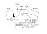
図1は、本発明の第1の実施形態における情報提供装置のシステム構成を示すブロック構成図である。図2は、図1に示す情報提供装置を搭載した自動車の運転席を示す図である。
【0021】
図1及び図2において、2は、オートクルーズ設定用のオートクルーズメインスイッチである。3は、ナビゲーション機能をオン・オフ可能なナビゲーションメインスイッチである。
【0022】
4は、表示装置15または16に表示される地図画像のスクロールを指示可能な地図スクロールスイッチである。5は、左右のウィンカランプのオン・オフ操作が可能なウィンカスイッチである。
【0023】
6は、経路誘導を希望する所望の目的地を設定可能な目的地設定スイッチである。7は、外部より受信したGPS(グローバル・ポジショニング・システム)信号に基づいて自車両の現在位置を検出するGPSセンサである。
【0024】
9は、自車両のヨーレートを検出するヨーレートセンサである。10は、自車両の走行状態として車速を検出する車速センサである。11は、自車両の操舵角度を検出する操作角センサである。
【0025】
12は、ドライバの凝視する方(以下、注視点)を検出する注視点検出センサである。13は、レーザレーダ、或はミリ波レーダ等を利用することにより、前方に存在する障害物の自車両に対する距離と位置とを検出する前方障害物センサである。
【0026】
14は、歩行者が前方に存在することをドライバに警報する機能をオン・オフ可能な歩行者警報用スイッチであり、後述する第2の実施形態で使用するが、係る警報機能は、イグニッションのオン・オフ状態に連動させることにより、歩行者警報用スイッチ14は省略しても良い。
【0027】
19は、ヘッドランプ、スモールランプ、フォグランプのオン・オフ操作が可能なライトスイッチである。尚、本実施形態では、雨天や夜間等の前方の視認性が良くない走行環境を、一例として、ドライバによるライトスイッチ19の操作状態によって判別するが、この方法に限られるものではなく、ワイパーの動作設定か可能なワイパースイッチの操作状態、所定の時間帯、或いは外部より通信によって入手した天候状況等を利用して判別しても良い。
【0028】
20は、自車両の周辺の走行環境として、渋滞等の交通情報を外部から受信するビーコン信号受信機である。
【0029】
15及び16は、地図データベース8に予め格納されている地図情報に基づく地図画像や、後述する障害物警報画像等を表示することにより、各種の情報を提供する液晶表示器またはヘッドアップディスプレイ等の表示装置である。
【0030】
ここで、表示装置15(第1表示器)は、自車両の運転席前方であってドライバが前方を凝視したときに大きな視線移動を行わずに容易に表示画像を見ることができる位置であって、ドライバにとって視認性の良好な高い位置(ダッシュボードの中央位置近傍であってもよい)に配設されている。また、表示装置16(第2表示器)は、表示装置15の配設位置と比較してドライバが前方を注視したときの視線範囲の外延部寄りとなるセンターコンソールに配設されている。
【0031】
17は、オートクルーズメインスイッチ2がオン状態に操作されたときに先行車両との所定の車間距離を維持すべく、エンジンのスロットル開度、自動変速機の変速動作、或いはブレーキ動作を行う加減速機構である(尚、第2の実施形態においては、前方に歩行者が存在するときに作動する)。18は、少なくともドライバへの情報提供を行うべく、人工合成音による各種の音声出力を行うスピーカである。
【0032】
23は、例えばステアリングホイールのコラムカバーに設けられ、ドライバの頭顔部に赤外光を投光する赤外投光ランプである。24は、例えばステアリングホイールのコラムカバーに設けられ、赤外投光ランプ23による頭顔からの反射光を撮影する赤外投光領域撮像カメラである。
【0033】
そして、1は、地図データベース8に予め格納されている地図情報に基づく地図画像の表示制御を行うと共に、GPSセンサ7によって検出された現在位置情報や、その現在位置情報に対応する地図情報等を利用して、乗員(ドライバ)が設定した所望の目的地への経路誘導を行う一般的なナビゲーション装置の制御機能と、前方障害物に関する表示及び音声出力による警報機能とを行う制御ユニットである。この制御ユニット1によるナビゲーション機能及び警報機能は、予めメモリに格納されたソフトウエアを、不図示のCPUが実行することによって実現される。
【0034】
以下の説明においては、本実施形態に係る特徴的な情報提供制御としての警報機能について詳細に説明するが、ここで、本実施形態について、図3を参照して概説する。
【0035】
本実施形態において、制御ユニット1は、注視点検出センサ12によって自車両のドライバの注視点を検出し、前方に存在する障害物について前方障害物センサ13によって自車両との距離及び位置が検出されているときには、その障害物が、検出された注視点を基準として設定した所定範囲(視野範囲の推定範囲)内に相当する位置に存在するか否かに応じて、その障害物に関して表示や音声によって行う情報提供の態様(提供タイミングの遅延や中止等)を変更する。また、所定範囲は、自車両の走行状態、走行環境、或いはドライバの運転技量に応じて補正する。
【0036】
即ち、本実施形態では、人間の視力は注視した位置(注視点)を基準とする周辺視野の外縁方向に向かって急激に悪くなる、という人間の視野特性に着目することにより、ドライバの視野範囲として推定した所定範囲内に障害物が存在するときには、その所定範囲外に障害物が存在するときと比較して障害物の存在をドライバが認識している可能性が高いと判断できるので、その所定範囲に対する障害物の存在位置に応じて、警報発報のタイミングを調整する。
【0037】
更に、上記の視野特性を基本として、更に、周辺視野は、移動速度が高くなるほど、ある対象に対する注意力が高まるほど、或いは視認性が低下するほど狭くなるという特性に着目し、それらの特性を図5に示す如く予めテーブル化しておき、実際に検出した状態に応じて、ドライバの周辺視野と推定する所定範囲の大きさを補正する(図4参照)。
【0038】
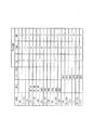
図5は、図1及び図2に示す各種センサによって検出した各種の状態に応じて、ドライバの周辺視野と推定する所定範囲の種類を設定するためのテーブルを示す図であり、この設定テーブルは、上記の周辺視野に関する人間の特性に基づき、予めメモリに記憶しておく。
【0039】
同図に示す各項目において、「車速」の項目は、車速センサ10の検出結果に応じて参照される。「環境」の項目は、ライトスイッチ19の操作状態や、ビーコン信号受信機20を介して受信した交通情報に応じて参照される。「ドライバ状態」の項目は、人間の瞳孔の大きさや動きは精神的な緊張に応じて変化するという特性に基づいて、後述する注視点検出センサ12によって検出可能な瞳孔径とその動きから検出し、その検出結果に応じて参照される。そして、「運転技量」の項目は、図10乃至図12を参照して後述する何れかの方法によって判定し、その判定結果に応じて参照される。
【0040】
尚、説明を単純にするため、図5には記載していないが、自車両の走行状態としては、車速の他にも、操舵角センサ11やヨーレートセンサ9の検出結果に基づいて検出可能な車両の挙動(旋回やカーブ等)を採用しても良い。
【0041】
次に、上述した機能を実現する具体的な処理について説明する。
【0042】
<基本処理>
図6は、第1の実施形態に係る車両用情報提供装置において情報提供の態様を決定する基本処理を示すフローチャートであり、この処理で決定(補正)されたパラメータを用いて、後述する制御処理(図13)が行われる。この基本処理は、制御ユニット1において当該制御処理とは別タスクにて並行して行われる。
【0043】
同図において、ステップS1:注視点検出センサ12により、ドライバの注視点を検出する(詳細は後述する)。
【0044】
ステップS2:車速センサ10等の検出結果に基づいて自車両の走行状態を判定する。また、ライトスイッチ19の操作状態やビーコン信号受信機20を介して受信した交通情報に基づいて自車両の周辺の走行環境を判定する。そして、図10乃至図12を参照して後述する何れかの手順によってドライバの運転技量を判定する。
【0045】
ステップS3:ステップS2における各種判定結果に応じて図5に示す設定テーブルを参照することにより、ドライバの周辺視野の推定範囲としての所定範囲(大、中、小)の大きさを決定すると共に、大きさを決定した所定範囲を、ステップS1にて検出したドライバの注視点を基準とする位置(座標位置)に設定する。
【0046】
ステップS4:ステップS3にて設定した所定範囲内に、前方障害物センサ13により検出された障害物の位置(座標位置)が含まれるかを判断し、この判断結果に応じて、ステップS5またはステップS6に進む。ここで、前方障害物センサ13が採用する座標系と、所定範囲の座標系とは共通に設定されている。
【0047】
ステップS5:ステップS4にて障害物が所定範囲内に存在すると判断されたので、その障害物の存在をドライバが認識している可能性が高い。そこで、本ステップでは、後述する制御処理において使用するパラメータ(所定距離LP、しきい値L1)を、障害物に関する情報のドライバへの報知を規制(報知タイミングの遅延または中止)可能な値に補正し、リターンする。より具体的には、報知タイミングの遅延または中止させるために、所定距離LP及びしきい値L1として、ステップS6で設定する所定の基準値より小さな値を選択する。ここで、情報提供を中止するには、しきい値L1を0に設定すれば良い。
【0048】
ステップS6:ステップS4にて障害物が所定範囲外に存在すると判断されたので、その障害物の存在をドライバが認識していない可能性が高い。そこで、本ステップでは、ステップS5とは異なり、障害物に関する情報のドライバへの報知を規制する必要はないので、後述する制御処理において使用するパラメータ(所定距離LP、しきい値L1)として、所定の基準値を選択し、リターンする。
【0049】
<注視点の検出>
ここで、ステップS1にて行う注視点の検出処理について説明する。まず、注視点の検出手順を説明するのに先立って、ドライバの頭顔の動きと瞳孔の動きとに関する実験結果の一例を、図8を参照して説明する。
【0050】
図8は、車線変更時のドライバの頭顔の動きと視線方向の動きに関する実験結果を示す図である。
【0051】
同図に示すように、車線変更の可否を判断する合流終了前30秒から15秒暗いまでの間においては、ドライバの頭顔は車両後方を確認するために何度も水平方向に大きく向けられ、且つ車線変更が終了するまでの間に渡って瞳孔が左右に激しく動いてサイドミラー及びルームミラーを注視していることが判ると共に、一方、垂直方向に対する頭顔部及び瞳孔の動き(視線方向の動き)には大きな変化が見られないことが判る。これにより、被験者の車線変更時の運転操作には、脇見等の無駄な目視が含まれていなかったと判断できる。そこで、本実施形態では、瞳孔の向き(視線方向)に基づいてドライバがどこを見ているかを表わす注視点を求め、ドライバの運転技量の判断要素として利用する。
【0052】
ここで、注視点検出センサ12によるドライバの注視点Pの検出方法について説明する。
【0053】
図7は、第1の実施形態における注視点検出センサ12のシステム構成を示すブロック図であり、本実施形態において以下に説明する各モジュールは、注視点検出センサ12が備える不図示のマイクロコンピュータが実行するソフトウエアの機能単位を表わす。
【0054】
同図に示すように、赤外投光ランプ23の投光部分と、赤外投光領域撮像カメラ24の受光部には、赤外透過フィルタ25が設けられており、注視点検出センサ12は、赤外投光領域撮像カメラ24から出力される映像信号に基づいて、画像処理モジュールにおいて一般的な2値化処理や特徴点の抽出処理を行うことによってドライバの頭顔部の画像を抽出し、その抽出した頭顔部の画像に基づいて、注視点検出モジュールにおいてドライバの注視点Pの算出すべく、頭顔方向Dhの検出、視線方向Dsの検出する。
【0055】
次に、注視点検出センサ12の具体的な機能について、図9を参照して説明する。
【0056】
図9は、第1の実施形態における注視点検出処理を示すフローチャートであり、画像処理モジュール及び注視点検出モジュールにより実現される機能を表わす。
【0057】
同図において、ステップS51:赤外投光ランプ23によってドライバの頭顔部に投光を行うと共に、赤外投光領域撮像カメラ24によって撮影した当該頭顔部のアナログ映像信号を画像処理モジュールに取り込み、その映像信号に一般的な2値化処理を施すことにより、ピクセル毎のデジタル多値画像データに変換する。
【0058】
ステップS52:入手した多値画像データから、一般的な画像処理手法を用いてドライバの顔画像部分を抽出し、その抽出した顔画像部分に含まれる複数の特徴点(例えば目頭、目尻、鼻孔等)の位置を検出する。
【0059】
ステップS53:抽出した顔画像部分の画像データから、赤外投光によってドライバの眼球の角膜に発生している反射点の位置と瞳孔の位置とを、一般的な画像処理手法を用いて検出する。
【0060】
ステップS54:ステップS52で検出した特徴点の位置に基づいて、所定の3次元座標空間におけるドライバの頭顔面の傾きを算出することにより、ドライバの頭顔が向けられている方向(頭顔方向)Dsを計測する。
【0061】
ステップS55:ステップS53で検出した角膜反射点と、ステップS54で検出した頭顔方向Dsとに基づいて、ドライバの視線の方向(注視方向)Dsを検出する。
【0062】
ステップS56:ステップS55で検出した注視方向Dsが、当該所定の3次元座標空間における座標として予め記憶している車両内外の所定位置(前方の遠方位置、前方の車両近傍位置、ルームミラー取り付け位置、左右のサイドミラー取り付け位置等)に対応するかを判断することにより、ドライバの注視点Pを検出し、その検出した注視点Pを表わすデータ(例えば、前方の遠方位置、前方の車両近傍位置、ルームミラー取り付け位置、左右のサイドミラー取り付け位置等をそれぞれ個別に表わす識別フラグ)を、制御ユニット1に出力し、リターンする。
【0063】
上述した注視点検出処理は、例えば、注視点検出センサ12のマイクロコンピュータ(不図示)の制御周期毎に行われ、検出された注視点Pを表わすデータ(識別フラグ)は、上述した図6に示すフローチャートのステップS1において、制御ユニット1内の注視点メモリ(RAM)に所定の検出回数分だけ時系列に記憶される。
【0064】
<運転技量の判定>
次に、制御ユニット1が実行するところの、図6に示すフローチャートのステップS2において実行される運転技量の求め方について説明する。本実施形態では、以下に説明する3種類の方法を想定しており、これらの方法の中から少なくとも1つを採用すれば良い。
【0065】
図10は、間接ミラーの注視頻度に基づく運転技量判定処理を示すフローチャートであり、この判定方法は、運転技量が比較的低いドライバは、一般に間接ミラー(左右のサイドミラー及びルームミラー)を利用した自車両後方の確認頻度が少ない(即ち、自車両の後方を見る余裕がない)という運転特性に基づいている。
【0066】
同図において、ステップS61A:ウィンカスイッチ5の操作状態と、操舵角センサ11によって検出された操舵角とにより、現在の運転操作状態が直進中の状態であるか、車線変更が終了した状態であるか、或いは左折が終了した状態であるかを判断する。
【0067】
ステップS62A:ステップS61Aの判断で直進中の状態であるときには、注視点メモリに記憶されている時系列の注視点データ(識別フラグ)を参照し、所定のTStraight秒間における間接ミラー(左右のサイドミラー及びルームミラー)の注視回数NStraightを計数する。
【0068】
ステップS63A:ステップS61Aの判断で車線変更が終了した状態であるときには、注視点メモリに記憶されている時系列の注視点データを参照し、車線変更開始から終了までのTLane秒間における間接ミラー(左右のサイドミラー及びルームミラー)の注視回数NLaneを計数する。
【0069】
ステップS64A:ステップS61Aの判断で左折が終了した状態であるときには、注視点メモリに記憶されている時系列の注視点データを参照し、左折開始から終了までのTLeft秒間における間接ミラー(左右のサイドミラー及びルームミラー)の注視回数NLeftを計数する。
【0070】
ステップS65A,ステップS66A:注視回数NStraight、注視回数NLane、注視回数NLeftが計数できているかを判断し(ステップS65A)、この判断で未計数のときにはステップS7に進み、計数済みのときには、それらの注視回数に基づいて、ドライバの運転技量レベルを判定する(ステップS66A)。
【0071】
即ち、ステップS66Aにおいては、注視回数NStraight、注視回数NLane、注視回数NLeftが全て所定値M(StraightM、LaneM、LeftM)以下であればレベル1(運転技量が低い)と判断し、これらの注視回数で何れかが所定値M以下であればレベル2(運転技量がやや低い)と判断する。また、NStraight>StraightM、NLane>LaneM、NLeft>LeftMのときにはレベル3(運転技量が普通)と判断し、これらの注視回数で何れかが所定値H((>所定値M):StraightH、LaneH、LeftH)以上のときにはレベル4(運転技量がやや高い)と判断し、NStraight>StraightH、NLane>LaneH、NLeft>LeftHのときにはレベル5(運転技量が高い)と判断する。
【0072】
尚、上記のように間接ミラーの注視頻度に基づく運転技量判定を行うにときに使用する所定値(所定回数)M及びHは、1回当たりの注視時間や、後方視界確認の必要性(例えば、交通量や高速道路等)に応じて補正すると良い。即ち、間接ミラーによる1回当たりの注視時間が所定の時間より短い場合にはこれらのしきい値を大きくし、長い場合には小さく補正すれば良い。また、自車両が走行中の道路種類が、一般道路の場合にはこれらのしきい値を大きくし、高速道路の場合にはこれらのしきい値を小さく補正する。また、自車両が走行中の道路の交通量が多い場合にはこれらのしきい値を大きくし、少ない場合にはこれらのしきい値を小さく補正する。
【0073】
ステップS67A:判定された5種類のレベルを、図5に示す設定テーブルの分類に合わせて、レベル1及び2の場合は運転技量が「低い」、レベル3の場合は運転技量が「普通」、レベル4及び5の場合は運転技量が「高い」と分類し、メモリに記憶する。
【0074】
図11は、車両周囲への注視頻度に基づく運転技量判定処理を示すフローチャートであり、この判定方法は、運転技量が比較的低いドライバは、一般に自車両前方の左右方向に対する注視範囲が狭い(即ち、自車両の周囲を見る余裕がない)という運転特性に基づいている。
【0075】
同図において、ステップS61B:上述したステップS61Aと同様に、ウィンカスイッチ5の操作状態と、操舵角センサ11により検出した操舵角とにより、現在の運転操作状態が直進中の状態であるか、車線変更が終了した状態であるか、或いは左折が終了した状態であるかを判断し、この判断で直進中以外のときにはステップS7に進み、直進中のときにはステップS62Bに進む。
【0076】
ステップS62B:ステップS61Bの判断で直進中の状態であるので、注視点メモリに記憶されている時系列の注視点データを参照し、所定のTStraight秒間における前方左方向の注視回数NStraightL、前方右方向の注視回数NStraightRを計数する。
【0077】
ステップS63B,ステップS64B:注視回数NStraightL及び注視回数NStraightRが計数できているかを判断し(ステップS63B)、この判断で未計数のときにはステップS7に進み、計数済みのときには、それらの注視回数に基づいて、ドライバの運転技量レベルを判定する(ステップS64B)。
【0078】
即ち、ステップS64Bにおいては、注視回数NStraightL及び注視回数NStraightRが何れも所定値M(StraightLM、StraightRM)以下であればレベル1(運転技量が低い)と判断し、これらの注視回数で何れかが所定値M以下であればレベル2(運転技量がやや低い)と判断する。また、NStraightR>StraightRM、NStraightL>StraightLMのときにはレベル3(運転技量が普通)と判断し、これらの注視回数で何れかが所定値H((>所定値M):StraightLH、StraightRH)以上のときにはレベル4(運転技量がやや高い)と判断し、NStraightR>StraightRH、NStraightL>StraightLHのときにはレベル5(運転技量が高い)と判断する。
【0079】
尚、上記のように車両周囲への注視頻度に基づく運転技量判定を行うにときに使用する所定値(所定回数)M及びHについても、間接ミラーの注視頻度に基づく運転技量判定の場合と同様に、1回当たりの注視時間や、後方視界確認の必要性(例えば、交通量や高速道路等)に応じて補正すると良い。
【0080】
ステップS67B:判定された運転技量を、上述した図10のステップS67Aと同様に3種類に分類し、メモリに記憶する。
【0081】
図12は、車両前方の遠方注視頻度に基づく運転技量判定処理を示すフローチャートであり、この判定方法は、運転技量が比較的低いドライバは、一般に自車両前方に対する注視距離が短い(即ち、自車両の遠方を見る余裕がない)という運転特性に基づいている。
【0082】
同図において、ステップS61C:上述したステップS61Aと同様に、ウィンカスイッチ5の操作状態と、操舵角センサ11により検出した操舵角とにより、現在の運転操作状態が直進中の状態であるか、車線変更が終了した状態であるか、或いは左折が終了した状態であるかを判断し、この判断で直進中以外のときにはステップS7に進み、直進中のときにはステップS62Cに進む。
【0083】
ステップS62C:ステップS61Cの判断で直進中の状態であるので、注視点メモリに記憶されている時系列の注視点データ(識別フラグ)を参照し、所定のTStraight秒間における前方の所定の遠方位置(例えば自車両前方の50mより遠方)の総注視時間NStraightF、所定の近傍位置(例えば自車両ボンネットの見切り位置から前方50m)の総注視時間NStraightNを、例えば、当該遠方位置及び近傍位置を注視したことを表わす識別フラグの計数値を当該所定のTStraight秒間の範囲内においてそれぞれ計数し、それらの計数値と所定の単位時間との積を算出することによって求める。
【0084】
ステップS63C,ステップS64C:総注視時間NStraightF及びNStraightNが算出できているかを判断し(ステップS63C)、この判断で未算出のときにはステップS7に進み、算出済みのときには、それらの総注視時間に基づいて、ドライバの運転技量レベルを判定する(ステップS64C)。
【0085】
即ち、ステップS64Cにおいては、総注視時間NStraightFとNStraightNとの比を算出し、その算出した比が所定値FrontPointLより小さいときにはレベル1(運転技量が低い)と判断し、その算出した比が所定値FrontPointLM(>FrontPointL)より大きいときにはレベル2(運転技量がやや低い)と判断する。また、その算出した比が所定値FrontPointM(>FrontPointLM)より大きいときにはレベル3(運転技量が普通)と判断し、その算出した比が所定値FrontPointHM(>FrontPointM)より大きいときにはレベル4(運転技量がやや高い)と判断し、その算出した比が所定値FrontPointH(>FrontPointHM)より大きいときにはレベル5(運転技量が高い)と判断する。
【0086】
尚、上記のように車両前方の遠方注視頻度に基づいて運転技量判定を行うにときに使用する所定値FrontPointL等のしきい値についても、間接ミラーの注視頻度に基づく運転技量判定の場合と同様に、1回当たりの注視時間や、後方視界確認の必要性(例えば、交通量や高速道路等)に応じて補正すると良い。
【0087】
ステップS67C:判定された運転技量を、上述した図10のステップS67Aと同様に3種類に分類し、メモリに記憶する。
【0088】
尚、運転技量の判定方法としては、単独走行時の走行車線内における車両のふらつき量に基づいて判定する方法があり、この方法においては、車両重心点の標準偏差を算出し、一般的な偏差値(例えば高速道路走行時には0.2m程度)を越えるふらつきを伴う場合に、運転技量が低いと判定する。
【0089】
また、他の方法として、前方車両との追従走行時における車間距離の変動と運転操作とに基づいて判定する方法があり、この方法においては、車間距離の変動が大きく、運転操作の操作量が多い場合に、運転技量が低いと判定する。
【0090】
更に他の方法として、制御ユニット1にて読みと利可能な記憶媒体にドライバの運転技量に関する情報(違反点数等)を記憶しておく方法がある。
【0091】
<制御処理>
次に、上述した基本処理にて決定されたパラメータを参照して行われる制御処理について説明する。
【0092】
図13は、第1の実施形態における車両用情報提供装置の制御処理を示すフローチャートであり、オートクルーズ用メインスイッチ2がオン状態に操作されるのに応じて開始される。
【0093】
同図において、ステップS11:車速センサ10、操舵角センサ11、ヨーレートセンサ9、並びに前方障害物センサ13の各センサの検出結果を入力する。
【0094】
ステップS12:ステップS11にて入力した車速センサ10、操舵角センサ11、そしてヨーレートセンサ9の検出結果に基づいて、自車両の進行路(自車両がこれから進行するであろう予測経路)を算出する。ここで、進行路は、本願出願人による先行する特開平7−220119号に開示された手順で算出すれば良い。
【0095】
ステップS13:算出した進行路上の自車両から所定距離LPの範囲内に障害物が存在するかを、前方障害物センサ13の検出結果に基づいて判断し、その判断結果に応じてステップS14またはステップS16に進む。ここで、所定距離LPは、上述した基本処理(図6)にて補正された値である。
【0096】
ステップS14:ステップS13の判断で所定距離LPの範囲内に障害物は存在しないと判断されたので、障害物に関する情報(警報)を行う必要はない。そこで、本ステップでは、自車速が予め設定された車速になるように、加減速機構17の制御を行う。
【0097】
ステップS15:ガイダンス表示用の内部処理フラグFc1,Fc2,Fc3を表示中止を表わす0にリセットする。
【0098】
ここで、内部処理フラグFc1は、単なる情報提供のための表示を指示するフラグである。内部処理フラグFc2は、障害物に対する1次警報としての情報提供のための表示を指示するフラグである。そして、内部処理フラグFc3は、障害物に対する2次警報としての情報提供のための表示を指示するフラグであり、1次警報と比較して緊急度が高い場合に設定される。
【0099】
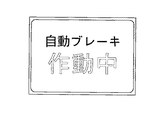
これらの内部処理フラグが1にセットされた場合に、表示装置15または16に表示されるガイダンス表示として、緊急度が比較的低い内部処理フラグFc1=1においては、図14の表示例によって車間距離を報知し、1次警報である内部処理フラグFc2=1においては、図15の表示例によって車間距離が自動的に調整されていることを報知し、そして、緊急度が最も高い2次警報である内部処理フラグFc3=1においては、図16の表示例によって自動的なブレーキ制動が行われていることを表示すれば良い。また、好適な実施形態においては、表示する画面の緊急度に応じて、2つの表示装置を使い分けると良い。
【0100】
ステップS16,ステップS17:ステップS13の判断で所定距離LPの範囲内に障害物が存在する判断されたので、その障害物が前回の制御周期において検出されていたかを判断し(ステップS16)、その判断の結果、前回の制御周期でも検出されていたときにはステップS18に進み、今回新たに検出された障害物であるときには、ステップS17において、ガイダンス表示用の内部処理フラグFc1を、表示を指示する1にセットすると共に、スピーカ18から単発人工音「ピッ」を出力する。好ましくは、ステップS17における音声出力の態様も、上述した基本処理(図6)にて補正された値に応じた音圧レベルにすると良い。
【0101】
ステップS18:前方に存在する障害物との距離Lが、上述した基本処理(図6)にて補正されたしきい値L1より短いかを判断し、この判断でNO(L≧L1)のときには、現時点における情報提供の緊急度はあまり高くないと判断できるのでステップS19に進み、YES(L<L1)のときには、緊急度の度合を判断するためにステップS21に進む。
【0102】
ステップS19,ステップS20:ガイダンス表示用の内部処理フラグFc2,Fc3を表示中止を表わす0にリセットし(ステップS19)、自車両とその先行車両との車間距離が予め設定された距離になるように、加減速機構17の制御を行う。
【0103】
ステップS21:前方に存在する障害物との距離Lが、所定のしきい値L2(<L1)より短いかを判断し(ステップS21)、この判断でNO(L≧L2)のときにはステップS25に進み、YES(L<L2)のときにはステップS22に進む。ここで、しきい値L2はしきい値L1とは異なり補正しないのは、しきい値L2を用いて判断する状況下においては、障害物との距離が短く緊急度が高いので、その障害物に対するドライバの認識の有無に関らずに迅速に情報提供を行い、障害物に対する注意を喚起するべきだからでる。
【0104】
ステップS22:緊急度が高く現在検出されている障害物についての2次警報が必要であると判断できるので、ガイダンス表示用の内部処理フラグFc3を1にセットすると共に、スピーカ18から連続的な人工音「ピッピッピッピッ」を出力する。好ましくは、ステップS22における音声出力の態様も、上述した基本処理(図6)にて補正された値に応じた音圧レベルにすると良い。
【0105】
ステップS23,ステップS24:ガイダンス表示用の内部処理フラグFc1,Fc2を表示中止を表わす0にリセットし(ステップS23)、自車両とその先行車両との車間距離が予め設定された距離になるように、加減速機構17による制動動作を行う(ステップS24)。
【0106】
ステップS25:現在検出されている障害物についての1次警報が必要であると判断できるので、ガイダンス表示用の内部処理フラグFc2を1にセットすると共に、スピーカ18から擬似的なクラクション音を出力する。好ましくは、ステップS25における音声出力の態様も、上述した基本処理(図6)にて補正された値に応じた音圧レベルにすると良い。
【0107】
ステップS26,ステップS27:ガイダンス表示用の内部処理フラグFc1,Fc3を表示中止を表わす0にリセットし(ステップS26)、自車両とその先行車両との車間距離が予め設定された距離になるように、加減速機構17による制動動作を行う(ステップS27)。
【0108】
ステップS28:ガイダンス表示用の内部処理フラグFc1乃至Fc3において1にセットされている何れかに対応する画像を、表示装置15または16に表示し、リターンする。
【0109】
上述した本実施形態によれば、障害物に対するドライバの認識の度合に応じた情報提供を効果的に行うことができる。
【0110】
また、所定範囲という情報提供のための基準値(所定距離LP、しきい値L1)が、ドライバの運転状態に大きく関与するパラメータ(走行環境、走行状態、運転技量)に応じて補正されるので、より効果的な情報提供を行うことができる。
【0111】
また、所定範囲内に障害物が位置する場合には、その障害物の存在をドライバが認識している可能性が高いので、そのような場合に、当該所定範囲外に障害物が存在する場合と比較して情報提供のタイミングが遅延されるので、ドライバの煩わしさを感じることを防ぎ、より効果的な情報提供を行うことができる。
【0112】
[第2の実施形態]
次に、上述した第1の実施形態に係る車両用情報提供装置を基本とする第2の実施形態を説明する。以下の説明においては、第1の実施形態と同様な構成については重複する説明を省略し、本実施形態における特徴的な部分を中心に説明する。
【0113】
本実施形態では、第1の実施形態と同様な基本処理にて設定されたパラメータを用いて、前方に存在する歩行者をドライバに認識させる警報機能を実現する情報提供装置について説明する。
【0114】
<制御処理>
図17は、第2の実施形態における車両用情報提供装置の制御処理を示すフローチャートであり、歩行者警報用メインスイッチ14がオン状態に操作されるのに応じて開始される。
【0115】
同図において、ステップS31:車速センサ10、操舵角センサ11、ヨーレートセンサ9、並びに前方障害物センサ13の各センサの検出結果を入力する。
【0116】
ステップS32:ステップS31にて入力した車速センサ10、操舵角センサ11、そしてヨーレートセンサ9の検出結果に基づいて、自車両の進行路を算出する。ここで、進行路は、本願出願人による先行する特開平10−100820号に開示された手順で算出すれば良い。
【0117】
ステップS33:算出した進行路上の自車両から所定距離LPの範囲内に歩行者が存在するかを、例えばレーザレーダやミリ波レーダ等の前方障害物センサ13による検出結果に基づいて判断し、その判断結果に応じてステップS34またはステップS35に進む。本実施形態においても、所定距離LPは、上述した基本処理(図6)にて補正された値である。
【0118】
ステップS34:ステップS33の判断で所定距離LPの範囲内に歩行者は存在しないと判断されたので、歩行者に関する情報(警報)を行う必要はない。そこで、本ステップでは、ガイダンス表示用の内部処理フラグFc1,Fc2を表示中止を表わす0にリセットし、リターンする。
【0119】
本実施形態において、内部処理フラグFc1は、歩行者に関する注意を促す緊急度があまり高くない情報提供としての表示を指示するフラグである。そして、内部処理フラグFc2は、歩行者に関する緊急度の高い警報としての情報提供のための表示を指示するフラグである。
【0120】
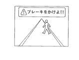
これらの内部処理フラグが1にセットされた場合に、表示装置15または16に表示されるガイダンス表示として、内部処理フラグFc1=1においては図18の表示例によって歩行者の存在を報知し、そして、警報である内部処理フラグFc2=1においては、図19の表示例を表示することによってドライバにブレーキ操作を促せば良い。また、好適な実施形態においては、表示する画面の緊急度に応じて、2つの表示装置を使い分けると良い。
【0121】
ステップS35,ステップS36:ステップS33の判断で所定距離LPの範囲内に歩行者が存在する判断されたので、その歩行者が前回の制御周期において検出されていたかを判断し(ステップS35)、その判断の結果、前回の制御周期でも検出されていたときにはステップS37に進み、今回新たに検出された歩行者であるときには、ステップS36において、ガイダンス表示用の内部処理フラグFc1を、表示を指示する1にセットすると共に、スピーカ18から単発人工音「ピッ」を出力する。好ましくは、ステップS36における音声出力の態様も、上述した基本処理(図6)にて補正された値に応じた音圧レベルにすると良い。
【0122】
ステップS37,ステップS38:前方に存在する歩行者との距離Lが、上述した基本処理(図6)にて補正されたしきい値L1より短いかを判断し(ステップS37)、この判断でYES(L<L1)のときにはステップS39に進み、NO(L≧L1)のときには、現時点における情報提供の緊急度はあまり高くないと判断できるので、ガイダンス表示用の内部処理フラグFc2を表示中止を表わす0にリセットする。
【0123】
ステップS39,ステップS40:現在検出されている歩行者に関する緊急度の高い警報が必要であると判断できるので、ガイダンス表示用の内部処理フラグFc2を1にセットすると共に、スピーカ18から擬似的なクラクション音を出力し(ステップS39)、ガイダンス表示用の内部処理フラグFc1を表示中止を表わす0にリセットする(ステップS40)。
【0124】
ステップS41:ガイダンス表示用の内部処理フラグFc1またはFc2において1にセットされている何れかに対応する画像を、表示装置15または16に表示し、リターンする。
【0125】
上述した本実施形態によれば、歩行者に対するドライバの認識の度合に応じた情報提供を効果的に行うことができる。
【0126】
また、所定範囲という情報提供のための基準値(所定距離LP、しきい値L1)が、ドライバの運転状態に大きく関与するパラメータ(走行環境、走行状態、運転技量)に応じて補正されるので、より効果的な情報提供を行うことができる。
【0127】
また、所定範囲内に歩行者が位置する場合には、その歩行者の存在をドライバが認識している可能性が高いので、そのような場合に、当該所定範囲外に障害物が存在する場合と比較して情報提供のタイミングが遅延されるので、ドライバの煩わしさを感じることを防ぎ、より効果的な情報提供を行うことができる。
【図面の簡単な説明】
【図1】本発明の第1の実施形態における情報提供装置のシステム構成を示すブロック構成図である。
【図2】図1に示す情報提供装置を搭載した自動車の運転席を示す図である。
【図3】ドライバの注視点と周辺視野とを説明する図である。
【図4】ドライバの周辺視野と推定する所定範囲の種類を例示する図である。
【図5】図1及び図2に示す各種センサによって検出した各種の状態に応じて、ドライバの周辺視野と推定する所定範囲の種類を設定するためのテーブルを示す図である。
【図6】第1の実施形態に係る車両用情報提供装置において情報提供の態様を決定する基本処理を示すフローチャートである。
【図7】第1の実施形態における注視点検出センサ12のシステム構成を示すブロック図である。
【図8】車線変更時のドライバの頭顔の動きと視線方向の動きに関する実験結果を示す図である。
【図9】第1の実施形態における注視点検出処理を示すフローチャートである。
【図10】間接ミラーの注視頻度に基づく運転技量判定処理を示すフローチャートである。
【図11】車両周囲への注視頻度に基づく運転技量判定処理を示すフローチャートである。
【図12】車両前方の遠方注視頻度に基づく運転技量判定処理を示すフローチャートである。
【図13】第1の実施形態における車両用情報提供装置の制御処理を示すフローチャートである。
【図14】第1の実施形態において内部処理フラグFc1=1において表示すべきガイダンス画面を例示する図である。
【図15】第1の実施形態において内部処理フラグFc2=1において表示すべきガイダンス画面を例示する図である。
【図16】第1の実施形態において内部処理フラグFc3=1において表示すべきガイダンス画面を例示する図である。
【図17】第2の実施形態における車両用情報提供装置の制御処理を示すフローチャートである。
【図18】第2の実施形態において内部処理フラグFc1=1において表示すべきガイダンス画面を例示する図である。
【図19】第2の実施形態において内部処理フラグFc2=1において表示すべきガイダンス画面を例示する図である。
【符号の説明】
1:制御ユニット,
2:オートクルーズメインスイッチ,
3:ナビゲーションメインスイッチ,
4:地図スクロールスイッチ,
5:ウィンカスイッチ,
6:目的地設定スイッチ,
7:GPSセンサ,
8:地図データベース,
9:ヨーレートセンサ,
10:車速センサ,
11:操舵角センサ,
12:注視点検出センサ,
13:前方障害物センサ,
14:歩行者警報用メインスイッチ,
15,16:表示装置,
17:加減速機構,
18:スピーカ,
23:赤外投光ランプ,
24:赤外投光領域撮像カメラ,
25:赤外透過フィルタ,[0001]
BACKGROUND OF THE INVENTION
The present invention relates to a vehicular information providing apparatus that informs a passenger of a vehicle of the state of an obstacle or the like existing around the vehicle by display or voice, for example, information suitable for being mounted on an automobile that is a typical vehicle. The present invention relates to a providing device.
[0002]
[Prior art]
2. Description of the Related Art Conventionally, there has been proposed an apparatus that detects an obstacle existing in front of a vehicle using a laser radar, a millimeter wave radar, or the like, and displays the detected obstacle in front of a driver's seat.
[0003]
As an example of such a technique, in Japanese Patent Application No. 6-230132, an observation area is set by detecting the line-of-sight direction of the driver, and the position of the obstacle around the vehicle detected by the radar, and the observation area. A device for displaying an alarm mark between the two has been proposed.
[0004]
Japanese Patent Application Laid-Open No. 11-115660 by the applicant of the present application proposes a device that displays a graphic representing the presence of an obstacle when a front obstacle is detected by a radar.
[0005]
According to these devices, the driver can easily grasp that there is an obstacle ahead, and can effectively support the driving operation.
[0006]
[Problems to be solved by the invention]
However, in the above conventional apparatus, when an obstacle is present, information on the obstacle is always provided. Therefore, if the driver recognizes the presence of the obstacle, providing information is troublesome. When a dangerous situation that is caught and notified actually occurs, attention cannot be effectively drawn.
[0007]
Therefore, an object of the present invention is to provide a vehicle information providing apparatus that effectively provides information on an obstacle according to the degree of recognition of the driver with respect to the obstacle.
[0008]
[Means for Solving the Problems]
In order to achieve the above object, a vehicle information providing apparatus according to the present invention is characterized by the following configuration.
[0009]
That is, an obstacle detection unit that detects a relative positional relationship of an obstacle existing ahead with respect to the host vehicle, a gazing point detection unit that detects a driver's gazing point, and a gazing point detected by the gazing point detection unit When the positional relationship is detected by the obstacle detecting means with respect to the obstacle existing in front of the range setting means for setting a predetermined range (estimated range of the peripheral visual field) with reference to the obstacle, the obstacle is An information providing unit that changes a mode of providing information on the obstacle according to whether or not it exists in a position corresponding to a predetermined range set by the range setting unit; Driving skill detecting means for detecting the driving skill of the driver based on the visual behavior of the driver of the own vehicle; With The range setting means corrects the size of the predetermined range according to the driving skill detected by the driving skill detection means. It is characterized by.
[0013]
Further, in a preferred embodiment, the information providing means provides information when the obstacle is present at a position corresponding to the predetermined range as compared with when the obstacle is present outside the predetermined range. It is preferable to restrict the provision (that is, delay or stop the information provision timing). However, even in this case, when it is determined that the urgency of providing information regarding the obstacle is high, it is preferable to release the information provision restriction.
[0014]
【The invention's effect】
According to the present invention described above, provision of a vehicle information providing apparatus that effectively provides information related to an obstacle according to the degree of recognition of the driver with respect to the obstacle is realized.
[0015]
In other words, when an obstacle is located within a predetermined range with the gazing point as a reference, it is highly likely that the driver recognizes the presence of the obstacle. According to the invention of
[0016]
Also , Place A reference value for providing information within a fixed range is a parameter that greatly affects the driving status of the driver (luck Since it is corrected according to the amount of change), it is possible to provide more effective information.
[0017]
In addition, when an obstacle is located within the predetermined range, the driver is likely to recognize the presence of the obstacle. In such a case, there is an obstacle outside the predetermined range. Claims that regulate the provision of information compared to 2 According to this invention, it is possible to prevent the driver from feeling troublesome and to provide more effective information.
[0018]
Claims 3 According to the invention, when the degree of urgency is high, for example, when the distance to the obstacle is short, information is provided promptly, so that the driver's attention to the obstacle can be efficiently called.
[0019]
DETAILED DESCRIPTION OF THE INVENTION
Hereinafter, a vehicle information providing apparatus according to the present invention will be described in detail with reference to the drawings as an embodiment in a case where the vehicle information providing apparatus is mounted on an automobile which is a typical vehicle.
[0020]
[First Embodiment]
FIG. 1 is a block diagram showing a system configuration of an information providing apparatus according to the first embodiment of the present invention. FIG. 2 is a diagram showing a driver's seat of an automobile equipped with the information providing apparatus shown in FIG.
[0021]
1 and 2,
[0022]
[0023]
[0024]
[0025]
[0026]
14 is a pedestrian warning switch that can turn on / off the function of warning the driver that a pedestrian is ahead, and is used in the second embodiment to be described later. The pedestrian warning switch 14 may be omitted by interlocking with the on / off state.
[0027]
[0028]
[0029]
15 and 16 are a liquid crystal display or a head-up display that provides various types of information by displaying a map image based on map information stored in advance in the
[0030]
Here, the display device 15 (first display) is a position in front of the driver's seat of the host vehicle, where the display image can be easily viewed without performing a large line of sight movement when the driver stares forward. Thus, the driver is disposed at a position with high visibility for the driver (may be near the center position of the dashboard). In addition, the display device 16 (second display) is disposed on the center console that is closer to the outward extension portion of the line-of-sight range when the driver gazes ahead than the position where the
[0031]
17 is an acceleration / deceleration that performs engine throttle opening, automatic transmission shift operation, or brake operation so as to maintain a predetermined inter-vehicle distance from the preceding vehicle when the auto-cruise
[0032]
[0033]
1 performs display control of the map image based on the map information stored in advance in the
[0034]
In the following description, the alarm function as characteristic information provision control according to the present embodiment will be described in detail. Here, the present embodiment will be outlined with reference to FIG.
[0035]
In the present embodiment, the
[0036]
That is, in this embodiment, the visual field range of the driver is determined by paying attention to the human visual field characteristic that the human visual acuity rapidly deteriorates toward the outer edge direction of the peripheral visual field with the gaze position (gaze point) as a reference. When there is an obstacle within the predetermined range estimated as, it can be determined that the driver is more likely to recognize the presence of the obstacle than when there is an obstacle outside the predetermined range. The alarm timing is adjusted according to the position of the obstacle with respect to the predetermined range.
[0037]
Furthermore, on the basis of the above visual field characteristics, the peripheral visual field further focuses on the characteristic that it becomes narrower as the moving speed increases, the attention to a certain object increases, or the visibility decreases. As shown in FIG. 5, a table is prepared in advance, and the size of the predetermined range estimated as the peripheral visual field of the driver is corrected according to the actually detected state (see FIG. 4).
[0038]
FIG. 5 is a diagram showing a table for setting the peripheral visual field of the driver and a predetermined range type to be estimated according to various states detected by the various sensors shown in FIGS. Based on the above-mentioned human characteristics relating to the peripheral visual field, it is stored in advance in a memory.
[0039]
In each item shown in the figure, the item “vehicle speed” is referred to according to the detection result of the
[0040]
Although not shown in FIG. 5 for the sake of simplicity, the traveling state of the host vehicle can be detected based on detection results of the
[0041]
Next, specific processing for realizing the functions described above will be described.
[0042]
<Basic processing>
FIG. 6 is a flowchart showing a basic process for determining a mode of providing information in the vehicle information providing apparatus according to the first embodiment, and a control process described later using the parameters determined (corrected) in this process. (FIG. 13) is performed. This basic processing is performed in parallel in a separate task from the control processing in the
[0043]
In the figure, step S1: the gaze
[0044]
Step S2: The traveling state of the host vehicle is determined based on the detection result of the
[0045]
Step S3: By referring to the setting table shown in FIG. 5 according to the various determination results in Step S2, the size of the predetermined range (large, medium, small) as the estimated range of the peripheral visual field of the driver is determined, The predetermined range whose size has been determined is set to a position (coordinate position) based on the gaze point of the driver detected in step S1.
[0046]
Step S4: It is determined whether or not the position (coordinate position) of the obstacle detected by the
[0047]
Step S5: Since it is determined in step S4 that the obstacle is within the predetermined range, the driver is highly likely to recognize the presence of the obstacle. Therefore, in this step, parameters (predetermined distance LP, threshold value L1) used in the control processing described later are corrected to values that can restrict (notify or stop the notification timing) information related to obstacles to the driver. And return. More specifically, in order to delay or stop the notification timing, a value smaller than the predetermined reference value set in step S6 is selected as the predetermined distance LP and the threshold value L1. Here, in order to stop providing information, the threshold value L1 may be set to 0.
[0048]
Step S6: Since it is determined in step S4 that the obstacle is outside the predetermined range, there is a high possibility that the driver does not recognize the presence of the obstacle. Therefore, in this step, unlike step S5, there is no need to regulate the notification of the information related to the obstacle to the driver. Therefore, as parameters (predetermined distance LP, threshold value L1) used in the control processing described later, Select the reference value and return.
[0049]
<Detection of gaze point>
Here, the gaze point detection process performed in step S1 will be described. First, prior to describing the gaze point detection procedure, an example of an experimental result regarding the movement of the driver's head and face and the movement of the pupil will be described with reference to FIG.
[0050]
FIG. 8 is a diagram showing experimental results regarding the movement of the driver's head and face and the movement in the line of sight when the lane is changed.
[0051]
As shown in the figure, during the period from 30 seconds before darkness to 15 seconds dark before the end of merging to determine whether or not to change lanes, the driver's head and face are greatly turned in the horizontal direction many times to confirm the rear of the vehicle. In addition, it can be seen that the pupil moves violently to the left and right until the lane change is finished, and is gazing at the side mirror and the rearview mirror, while the head and face movements in the vertical direction (the direction of the line of sight) It can be seen that there is no significant change in Thereby, it can be determined that the driving operation at the time of changing the lane of the subject did not include useless visual observation such as a side look. Therefore, in the present embodiment, a gazing point indicating where the driver is looking is obtained based on the direction of the pupil (the direction of the line of sight), and is used as a determination factor of the driving skill of the driver.
[0052]
Here, a method of detecting the driver's gazing point P by the gazing
[0053]
FIG. 7 is a block diagram showing the system configuration of the gazing
[0054]
As shown in the figure, an
[0055]
Next, specific functions of the gazing
[0056]
FIG. 9 is a flowchart showing the gazing point detection process in the first embodiment, and shows functions realized by the image processing module and the gazing point detection module.
[0057]
In the figure, step S51: the driver's head face is projected by the
[0058]
Step S52: The driver's face image portion is extracted from the obtained multi-value image data using a general image processing method, and a plurality of feature points (for example, the eyes, corners of the eyes, nostrils, etc.) included in the extracted face image portion. ) Position is detected.
[0059]
Step S53: From the extracted image data of the face image portion, the position of the reflection point and the position of the pupil generated in the cornea of the driver's eyeball by infrared projection are detected using a general image processing technique. .
[0060]
Step S54: Based on the position of the feature point detected in step S52, by calculating the inclination of the driver's head face in a predetermined three-dimensional coordinate space, the direction in which the driver's head face is directed (head face direction). Ds is measured.
[0061]
Step S55: A direction (gaze direction) Ds of the driver's line of sight is detected based on the corneal reflection point detected in step S53 and the head-face direction Ds detected in step S54.
[0062]
Step S56: The gaze direction Ds detected in Step S55 is a predetermined position inside or outside the vehicle that is stored in advance as coordinates in the predetermined three-dimensional coordinate space (front far position, front vehicle vicinity position, room mirror mounting position, By determining whether the left and right side mirror mounting positions correspond to each other, the driver's gazing point P is detected, and the data indicating the detected gazing point P (for example, the front distant position, the front vehicle vicinity position, The identification flags indicating the rearview mirror mounting position and the left and right side mirror mounting positions are output to the
[0063]
The gazing point detection process described above is performed, for example, every control cycle of a microcomputer (not shown) of the gazing
[0064]
<Determination of driving skill>
Next, how to obtain the driving skill executed in step S2 of the flowchart shown in FIG. 6 executed by the
[0065]
FIG. 10 is a flowchart showing a driving skill determination process based on the indirect mirror gaze frequency. In this determination method, a driver with a relatively low driving skill generally uses an indirect mirror (left and right side mirrors and a room mirror). This is based on the driving characteristic that the frequency of confirmation behind the host vehicle is low (that is, there is no room to look behind the host vehicle).
[0066]
In the figure, step S61A: the current driving operation state is a straight traveling state or a lane change is completed based on the operation state of the
[0067]
Step S62A: When the vehicle is traveling straight as determined in Step S61A, the time-series gaze point data (identification flag) stored in the gaze point memory is referred to, and indirect mirrors (left and right side mirrors) for a predetermined TS Straight seconds. And room mirror) are counted.
[0068]
Step S63A: When the lane change has been completed in step S61A, the time series gaze point data stored in the gaze point memory is referred to, and the indirect mirrors in the lane seconds from the start to the end of the lane change (left and right) NLane) is counted.
[0069]
Step S64A: When the left turn is finished as determined in step S61A, the time series gaze point data stored in the gaze point memory is referred to, and the indirect mirror (left and right side mirrors) for TLeft seconds from the start to the end of the left turn is referred to. Mirror and room mirror) NLeft is counted.
[0070]
Step S65A, Step S66A: It is determined whether or not the number of gazes NStraight, the number of gazes NLane, and the number of gazes NLeft have been counted (step S65A), and if this count has not been counted, the process proceeds to step S7. Based on the number of times, the driving skill level of the driver is determined (step S66A).
[0071]
That is, in step S66A, if the number of gazes NStraight, the number of gazes NLane, and the number of gazes NLeft are all equal to or less than a predetermined value M (StraightM, LaneM, LeftM), it is determined as level 1 (the driving skill is low). If any of them is equal to or less than the predetermined value M, it is determined that the level is 2 (the driving skill is slightly low). Further, when NS Straight> Straight M, NS Lane> Lane M, and N Left> Left M, it is determined that the level is 3 (the driving skill is normal), and any one of these gaze counts is a predetermined value H ((> predetermined value M): Straight H, Lane H, When it is equal to or greater than (LeftH), it is determined that the level is 4 (the driving skill is slightly high), and when NS Straight> StraightH, NLane> LaneH, and NLeft> LeftH, it is determined that the level is 5 (the driving skill is high).
[0072]
In addition, the predetermined values (predetermined number of times) M and H used when performing the driving skill determination based on the gaze frequency of the indirect mirror as described above are the gaze time per time and the necessity of confirmation of the rear view (for example, It may be corrected according to traffic volume, highway, etc.). That is, these threshold values may be increased when the gaze time per one time by the indirect mirror is shorter than a predetermined time, and corrected when it is longer. If the road type on which the host vehicle is traveling is a general road, these threshold values are increased, and if the road type is an expressway, these threshold values are corrected to be smaller. Further, when the traffic volume on the road on which the host vehicle is traveling is large, these threshold values are increased, and when the traffic volume is small, these threshold values are corrected to be small.
[0073]
Step S67A: In accordance with the determined five levels according to the classification of the setting table shown in FIG. 5, the driving skill is “low” for
[0074]
FIG. 11 is a flowchart showing a driving skill determination process based on the gaze frequency around the vehicle. In this determination method, a driver with a relatively low driving skill generally has a narrow gaze range in the left-right direction in front of the host vehicle (that is, , Based on the driving characteristics of having no room to look around the vehicle.
[0075]
In the figure, step S61B: As in step S61A described above, whether the current driving operation state is a straight traveling state or not based on the operation state of the
[0076]
Step S62B: Since the vehicle is traveling straight in the determination of Step S61B, the time-series gaze point data stored in the gaze point memory is referred to, and the number of gazes NStraightL in the front left direction in the predetermined TS Straight seconds, the front right direction The number of gazes NS StraightR is counted.
[0077]
Step S63B, Step S64B: It is determined whether or not the gaze count NStraightL and the gaze count NStraightR have been counted (step S63B). If this count has not been counted, the process proceeds to step S7. The driver's driving skill level is determined (step S64B).
[0078]
That is, in step S64B, if both the number of gaze NSstraightL and the number of gaze NSstraightR are equal to or less than a predetermined value M (StraightLM, StraightRM), it is determined that the level is 1 (the driving skill is low). If it is less than or equal to the value M, it is determined that the level is 2 (the driving skill is slightly low). Further, when NS Straight R> Straight RM and NS Straight L> Straight LM, it is determined that the level is 3 (the driving skill is normal). When any of these gaze counts is a predetermined value H ((> predetermined value M): Straight LH, Straight RH) 4 (the driving skill is slightly high). When NS StraightR> Straight RH and NS Straight L> Straight LH, it is determined that the level is 5 (the driving skill is high).
[0079]
As described above, the predetermined values (predetermined number of times) M and H used when determining the driving skill based on the gaze frequency around the vehicle are the same as in the case of the driving skill determination based on the gaze frequency of the indirect mirror. Moreover, it is good to correct | amend according to the gaze time per time and the necessity (for example, traffic volume, a highway, etc.) of a back view confirmation.
[0080]
Step S67B: The determined driving skill is classified into three types as in step S67A of FIG. 10 described above, and stored in the memory.
[0081]
FIG. 12 is a flowchart showing a driving skill determination process based on a distant gaze frequency in front of the vehicle. In this determination method, a driver with a relatively low driving skill generally has a short gaze distance with respect to the front of the own vehicle (that is, the own vehicle). Based on driving characteristics).
[0082]
In the figure, Step S61C: As in Step S61A described above, whether the current driving operation state is a straight traveling state or not based on the operation state of the
[0083]
Step S62C: Since the vehicle is traveling straight in the determination of Step S61C, the time series gaze point data (identification flag) stored in the gaze point memory is referred to, and a predetermined far position in front of a predetermined TS Straight seconds ( For example, gaze at the total gaze time NStraightF for a distance from the front of the host vehicle NStraight F and the total gaze time NStraightN for a predetermined vicinity position (for example, 50 m ahead from the parting position of the host vehicle bonnet). Each of the count values of the identification flag representing the number is counted within a range of the predetermined TS Straight seconds, and the product of the count value and a predetermined unit time is calculated.
[0084]
Step S63C, Step S64C: It is determined whether or not the total gaze time NStraightF and NStraightN are calculated (step S63C). If not yet calculated in this determination, the process proceeds to step S7, and if calculated, based on the total gaze time. The driving skill level of the driver is determined (step S64C).
[0085]
That is, in step S64C, the ratio of the total gaze time NStraightF and NStraightN is calculated. When the calculated ratio is smaller than the predetermined value FrontPointL, it is determined that the level is 1 (the driving skill is low), and the calculated ratio is the predetermined value. When it is larger than FrontPointLM (> FrontPointL), it is judged as level 2 (driving skill is slightly low). Further, when the calculated ratio is larger than the predetermined value FrontPointM (> FrontPointLM), it is determined as level 3 (driving skill is normal), and when the calculated ratio is larger than the predetermined value FrontPointHM (> FrontPointM), level 4 (driving skill is If the calculated ratio is greater than the predetermined value FrontPointH (> FrontPointHM), it is determined that the level is 5 (the driving skill is high).
[0086]
As described above, the threshold value such as the predetermined value FrontPointL used when the driving skill determination is performed based on the distance gaze frequency in front of the vehicle is the same as in the case of the driving skill determination based on the gaze frequency of the indirect mirror. Moreover, it is good to correct | amend according to the gaze time per time and the necessity (for example, traffic volume, a highway, etc.) of a back view confirmation.
[0087]
Step S67C: The determined driving skill is classified into three types as in step S67A of FIG. 10 described above, and stored in the memory.
[0088]
Incidentally, as a method for determining the driving skill, there is a method of determining based on the amount of wobbling of the vehicle in the traveling lane during single traveling. In this method, the standard deviation of the vehicle center of gravity is calculated and the general deviation is calculated. It is determined that the driving skill is low when there is a fluctuation exceeding a value (for example, about 0.2 m when traveling on a highway).
[0089]
In addition, as another method, there is a method of determining based on the variation in the inter-vehicle distance and the driving operation at the time of the follow-up traveling with the preceding vehicle. When there are many, it determines with driving skill being low.
[0090]
As another method, there is a method of storing information (such as the number of violations) on the driving skill of the driver in a storage medium that can be read by the
[0091]
<Control processing>
Next, control processing performed with reference to the parameters determined in the basic processing described above will be described.
[0092]
FIG. 13 is a flowchart showing a control process of the vehicle information providing apparatus in the first embodiment, which is started when the auto-cruise
[0093]
In the figure, step S11: The detection results of each of the
[0094]
Step S12: Based on the detection results of the
[0095]
Step S13: It is determined based on the detection result of the
[0096]
Step S14: Since it is determined in step S13 that there is no obstacle within the predetermined distance LP, it is not necessary to perform information (alarm) regarding the obstacle. Therefore, in this step, the acceleration /
[0097]
Step S15: The internal processing flags Fc1, Fc2, and Fc3 for displaying guidance are reset to 0 indicating display stop.
[0098]
Here, the internal processing flag Fc1 is a flag for instructing a display for simply providing information. The internal processing flag Fc2 is a flag for instructing display for providing information as a primary alarm for an obstacle. The internal processing flag Fc3 is a flag for instructing a display for providing information as a secondary alarm for an obstacle, and is set when the degree of urgency is higher than that of the primary alarm.
[0099]
When these internal processing flags are set to 1, as the guidance display displayed on the
[0100]
Step S16, Step S17: Since it is determined in step S13 that an obstacle exists within the range of the predetermined distance LP, it is determined whether the obstacle has been detected in the previous control cycle (step S16). As a result of the determination, if it has been detected even in the previous control cycle, the process proceeds to step S18. If it is a newly detected obstacle this time, in step S17, an instruction to display the internal processing flag Fc1 for guidance display is indicated. And a single artificial sound “beep” is output from the
[0101]
Step S18: It is determined whether the distance L to the obstacle existing ahead is shorter than the threshold value L1 corrected in the above-described basic processing (FIG. 6). If this determination is NO (L ≧ L1) Since it can be determined that the urgency level of information provision at the present time is not so high, the process proceeds to step S19. When YES (L <L1), the process proceeds to step S21 in order to determine the degree of urgency.
[0102]
Steps S19 and S20: The internal processing flags Fc2 and Fc3 for displaying the guidance are reset to 0 indicating the display stop (step S19) so that the distance between the host vehicle and the preceding vehicle becomes a preset distance. The acceleration /
[0103]
Step S21: It is determined whether the distance L to the obstacle existing ahead is shorter than a predetermined threshold value L2 (<L1) (step S21). If this determination is NO (L ≧ L2), the process proceeds to step S25. If YES (L <L2), the process proceeds to step S22. Here, unlike the threshold value L1, the threshold value L2 is not corrected because the distance from the obstacle is short and the degree of urgency is high in the situation where the threshold value L2 is used. This is because information should be provided promptly regardless of whether the driver is aware of or not, and attention should be paid to obstacles.
[0104]
Step S22: Since it can be determined that the secondary alarm for the obstacle with high urgency level and the currently detected obstacle is necessary, the internal processing flag Fc3 for guidance display is set to 1 and continuous artificial Outputs the sound “beep-beep-beep”. Preferably, the sound output mode in step S22 is also set to a sound pressure level corresponding to the value corrected in the basic processing (FIG. 6) described above.
[0105]
Steps S23 and S24: The internal processing flags Fc1 and Fc2 for displaying the guidance are reset to 0 indicating display stop (step S23), and the distance between the host vehicle and the preceding vehicle is set to a preset distance. Then, the braking operation by the acceleration /
[0106]
Step S25: Since it can be determined that the primary alarm for the currently detected obstacle is necessary, the internal processing flag Fc2 for guidance display is set to 1 and a pseudo horn sound is output from the
[0107]
Steps S26 and S27: Guidance display internal processing flags Fc1 and Fc3 are reset to 0 indicating display stop (step S26), so that the distance between the host vehicle and the preceding vehicle becomes a preset distance. Then, the braking operation by the acceleration /
[0108]
Step S28: The image corresponding to any one of the internal processing flags Fc1 to Fc3 for displaying guidance is set on the
[0109]
According to this embodiment described above, it is possible to effectively provide information according to the degree of recognition of the driver with respect to the obstacle.
[0110]
In addition, the reference value (predetermined distance LP, threshold value L1) for providing information as a predetermined range is corrected according to parameters (traveling environment, traveling state, driving skill) that are greatly involved in the driving state of the driver It is possible to provide more effective information.
[0111]
In addition, when an obstacle is located within the predetermined range, the driver is likely to recognize the presence of the obstacle. In such a case, there is an obstacle outside the predetermined range. Since the timing of providing information is delayed compared to the above, it is possible to prevent the driver from feeling troublesome and to provide more effective information.
[0112]
[Second Embodiment]
Next, a second embodiment based on the vehicle information providing apparatus according to the first embodiment described above will be described. In the following description, the description similar to that of the first embodiment will be omitted, and the description will focus on the characteristic part of the present embodiment.
[0113]
In the present embodiment, an information providing apparatus that realizes an alarm function that allows a driver to recognize a pedestrian existing ahead by using parameters set in the same basic process as in the first embodiment will be described.
[0114]
<Control processing>
FIG. 17 is a flowchart showing a control process of the vehicle information providing apparatus according to the second embodiment, which is started in response to the pedestrian warning main switch 14 being operated to the on state.
[0115]
In the figure, step S31: The detection result of each sensor of the
[0116]
Step S32: Based on the detection results of the
[0117]
Step S33: It is determined whether there is a pedestrian within the range of the predetermined distance LP from the own vehicle on the calculated traveling path based on a detection result by the
[0118]
Step S34: Since it is determined in step S33 that there is no pedestrian within the range of the predetermined distance LP, it is not necessary to perform information (alarm) on the pedestrian. Therefore, in this step, the internal processing flags Fc1 and Fc2 for guidance display are reset to 0 indicating display stop and the process returns.
[0119]
In the present embodiment, the internal processing flag Fc1 is a flag for instructing display as information provision in which the degree of urgency for a pedestrian is not so high. The internal processing flag Fc2 is a flag for instructing display for providing information as a warning with a high degree of urgency related to a pedestrian.
[0120]
When these internal processing flags are set to 1, as the guidance display displayed on the
[0121]
Step S35, Step S36: Since it is determined in step S33 that a pedestrian exists within the range of the predetermined distance LP, it is determined whether the pedestrian has been detected in the previous control cycle (step S35). As a result of the determination, if it has been detected even in the previous control cycle, the process proceeds to step S37, and if it is a newly detected pedestrian this time, in step S36, display of the internal processing flag Fc1 for guidance display is instructed 1 And a single artificial sound “beep” is output from the
[0122]
Step S37, Step S38: It is determined whether the distance L with the pedestrian existing ahead is shorter than the threshold value L1 corrected in the basic processing (FIG. 6) described above (Step S37). When (L <L1), the process proceeds to step S39. When NO (L ≧ L1), it can be determined that the urgency level of information provision at the present time is not so high, so that the internal processing flag Fc2 for guidance display is displayed to be stopped. Reset to zero.
[0123]
Step S39, Step S40: Since it can be determined that an alarm with a high degree of urgency related to the pedestrian currently detected is necessary, the internal processing flag Fc2 for guidance display is set to 1, and the pseudo horn from the
[0124]
Step S41: An image corresponding to any of the guidance display internal processing flag Fc1 or Fc2 set to 1 is displayed on the
[0125]
According to this embodiment mentioned above, the information provision according to the driver's recognition degree with respect to a pedestrian can be performed effectively.
[0126]
In addition, the reference value (predetermined distance LP, threshold value L1) for providing information as a predetermined range is corrected according to parameters (traveling environment, traveling state, driving skill) that are greatly involved in the driving state of the driver It is possible to provide more effective information.
[0127]
In addition, when a pedestrian is located within a predetermined range, it is highly likely that the driver recognizes the presence of the pedestrian. In such a case, an obstacle exists outside the predetermined range. Since the timing of providing information is delayed as compared with the above, it is possible to prevent the driver from feeling troublesome and to provide more effective information.
[Brief description of the drawings]
FIG. 1 is a block configuration diagram showing a system configuration of an information providing apparatus according to a first embodiment of the present invention.
FIG. 2 is a diagram showing a driver's seat of an automobile equipped with the information providing apparatus shown in FIG.
FIG. 3 is a diagram illustrating a driver's gaze point and peripheral vision.
FIG. 4 is a diagram illustrating an example of a predetermined range to be estimated as a peripheral visual field of a driver.
FIG. 5 is a diagram showing a table for setting a peripheral visual field of a driver and a predetermined range type to be estimated according to various states detected by various sensors shown in FIGS. 1 and 2;
FIG. 6 is a flowchart showing basic processing for determining a mode of providing information in the vehicle information providing apparatus according to the first embodiment.
FIG. 7 is a block diagram showing a system configuration of a gazing
FIG. 8 is a diagram showing experimental results regarding the movement of the driver's head and face and the movement in the line of sight when changing lanes.
FIG. 9 is a flowchart showing a gazing point detection process in the first embodiment.
FIG. 10 is a flowchart showing a driving skill determination process based on a gaze frequency of an indirect mirror.
FIG. 11 is a flowchart showing a driving skill determination process based on a gaze frequency around the vehicle.
FIG. 12 is a flowchart showing a driving skill determination process based on a distance gaze frequency in front of the vehicle.
FIG. 13 is a flowchart showing a control process of the vehicle information providing apparatus in the first embodiment.
FIG. 14 is a diagram illustrating a guidance screen to be displayed when the internal processing flag Fc1 = 1 in the first embodiment.
FIG. 15 is a diagram illustrating a guidance screen to be displayed when the internal processing flag Fc2 = 1 in the first embodiment.
FIG. 16 is a diagram illustrating a guidance screen to be displayed when the internal processing flag Fc3 = 1 in the first embodiment.
FIG. 17 is a flowchart showing a control process of the vehicle information providing apparatus in the second embodiment.
FIG. 18 is a diagram illustrating a guidance screen to be displayed when the internal processing flag Fc1 = 1 in the second embodiment.
FIG. 19 is a diagram illustrating a guidance screen to be displayed when the internal processing flag Fc2 = 1 in the second embodiment.
[Explanation of symbols]
1: control unit,
2: Auto cruise main switch,
3: Navigation main switch,
4: Map scroll switch,
5: Winker switch,
6: Destination setting switch,
7: GPS sensor,
8: Map database,
9: Yaw rate sensor,
10: Vehicle speed sensor,
11: Steering angle sensor,
12: Gaze point detection sensor,
13: Front obstacle sensor,
14: Pedestrian alarm main switch,
15, 16: display device,
17: Acceleration / deceleration mechanism,
18: Speaker,
23: Infrared projection lamp,
24: Infrared projection area imaging camera,
25: Infrared transmission filter,
Claims (3)
前記自車両のドライバの注視点を検出する注視点検出手段と、
前記注視点検出手段によって検出された注視点を基準とする所定範囲を設定する範囲設定手段と、
前方に存在する障害物について前記障害物検出手段によって位置関係が検出されているときに、その障害物が、前記範囲設定手段によって設定されている所定範囲内に相当する位置に存在するか否かに応じて、その障害物に関する情報提供の態様を変更する情報提供手段と、
前記自車両のドライバの視認行動に基づいて、そのドライバの運転技量を検出する運転技量検出手段と、を備え、
前記範囲設定手段は、前記所定範囲の大きさを、前記運転技量検出手段によって検出された運転技量に応じて補正することを特徴とする車両用情報提供装置。Obstacle detection means for detecting the relative positional relationship of the obstacle present ahead with respect to the host vehicle;
Gazing point detection means for detecting the gazing point of the driver of the host vehicle;
Range setting means for setting a predetermined range based on the gazing point detected by the gazing point detection means;
Whether or not the obstacle exists in a position corresponding to a predetermined range set by the range setting means when the positional relationship is detected by the obstacle detection means with respect to an obstacle existing ahead And an information providing means for changing a mode of providing information related to the obstacle,
Driving skill detection means for detecting the driving skill of the driver based on the visual recognition behavior of the driver of the host vehicle ,
The range setting means corrects the size of the predetermined range according to the driving skill detected by the driving skill detection means .
Priority Applications (1)
| Application Number | Priority Date | Filing Date | Title |
|---|---|---|---|
| JP2000180294A JP4385392B2 (en) | 2000-06-15 | 2000-06-15 | Vehicle information providing device |
Applications Claiming Priority (1)
| Application Number | Priority Date | Filing Date | Title |
|---|---|---|---|
| JP2000180294A JP4385392B2 (en) | 2000-06-15 | 2000-06-15 | Vehicle information providing device |
Publications (2)
| Publication Number | Publication Date |
|---|---|
| JP2001357498A JP2001357498A (en) | 2001-12-26 |
| JP4385392B2 true JP4385392B2 (en) | 2009-12-16 |
Family
ID=18681425
Family Applications (1)
| Application Number | Title | Priority Date | Filing Date |
|---|---|---|---|
| JP2000180294A Expired - Fee Related JP4385392B2 (en) | 2000-06-15 | 2000-06-15 | Vehicle information providing device |
Country Status (1)
| Country | Link |
|---|---|
| JP (1) | JP4385392B2 (en) |
Cited By (2)
| Publication number | Priority date | Publication date | Assignee | Title |
|---|---|---|---|---|
| KR101646449B1 (en) | 2015-02-12 | 2016-08-05 | 현대자동차주식회사 | Gaze recognition system and method |
| KR20190065124A (en) * | 2017-12-01 | 2019-06-11 | 주식회사 스트라드비젼 | Driving assistant device and driving assitant method |
Families Citing this family (50)
| Publication number | Priority date | Publication date | Assignee | Title |
|---|---|---|---|---|
| DE10218698A1 (en) * | 2002-04-26 | 2003-11-13 | Bosch Gmbh Robert | Driver assistance system |
| JP2004030212A (en) * | 2002-06-25 | 2004-01-29 | Toyota Central Res & Dev Lab Inc | Information providing apparatus for vehicle |
| JP4275507B2 (en) * | 2003-10-28 | 2009-06-10 | 富士通テン株式会社 | Driving assistance device |
| JP4277678B2 (en) * | 2003-12-17 | 2009-06-10 | 株式会社デンソー | Vehicle driving support device |
| JP4238718B2 (en) * | 2003-12-18 | 2009-03-18 | 株式会社デンソー | Obstacle detection device for vehicle |
| JP4206928B2 (en) * | 2004-01-19 | 2009-01-14 | 株式会社デンソー | Collision possibility judgment device |
| JP4026145B2 (en) * | 2004-01-20 | 2007-12-26 | マツダ株式会社 | Image display device for vehicle |
| JP4255880B2 (en) * | 2004-05-17 | 2009-04-15 | 富士通テン株式会社 | Inter-vehicle collision prevention support system and inter-vehicle collision prevention support device |
| JP4585275B2 (en) * | 2004-11-01 | 2010-11-24 | 株式会社オーテックジャパン | Driver characteristic value acquisition device and driving support device |
| JP4604691B2 (en) * | 2004-12-07 | 2011-01-05 | 日産自動車株式会社 | Alarm device for vehicle, alarm method of vehicle surrounding situation |
| JP4760113B2 (en) * | 2005-04-27 | 2011-08-31 | トヨタ自動車株式会社 | Driver state estimation device |
| DE102005038855A1 (en) | 2005-08-12 | 2007-02-15 | Takata-Petri Ag | steering wheel assembly |
| JP4815943B2 (en) * | 2005-08-19 | 2011-11-16 | 株式会社デンソー | Hazardous area information display device |
| JP4353162B2 (en) | 2005-09-26 | 2009-10-28 | トヨタ自動車株式会社 | Vehicle surrounding information display device |
| JP4926437B2 (en) * | 2005-09-28 | 2012-05-09 | 富士重工業株式会社 | Vehicle driving support device |
| US7884705B2 (en) * | 2005-12-12 | 2011-02-08 | Panasonic Corporation | Safety-drive assistance device |
| JP4509042B2 (en) | 2006-02-13 | 2010-07-21 | 株式会社デンソー | Hospitality information provision system for automobiles |
| JP2007249364A (en) | 2006-03-14 | 2007-09-27 | Denso Corp | Safe driving support system and device |
| JP4722777B2 (en) * | 2006-06-21 | 2011-07-13 | 本田技研工業株式会社 | Obstacle recognition judgment device |
| JP4835295B2 (en) * | 2006-07-14 | 2011-12-14 | 株式会社デンソー | Vehicle driving force control device |
| JP4882587B2 (en) * | 2006-08-09 | 2012-02-22 | 株式会社デンソー | Vehicle information providing device |
| WO2008029802A1 (en) * | 2006-09-04 | 2008-03-13 | Panasonic Corporation | Travel information providing device |
| JP5003129B2 (en) * | 2006-12-01 | 2012-08-15 | マツダ株式会社 | Vehicle planning support system, vehicle planning support program, and vehicle planning support method |
| JP4762939B2 (en) * | 2007-03-08 | 2011-08-31 | トヨタ自動車株式会社 | Vehicle monitoring device |
| JP4480755B2 (en) * | 2007-12-04 | 2010-06-16 | カルソニックカンセイ株式会社 | Head-up display device for vehicle |
| JP5261045B2 (en) * | 2008-07-03 | 2013-08-14 | 富士重工業株式会社 | Vehicle driving support device |
| JP2010128645A (en) * | 2008-11-26 | 2010-06-10 | Equos Research Co Ltd | Information providing system and method |
| JP5042296B2 (en) * | 2009-12-02 | 2012-10-03 | 本田技研工業株式会社 | Gaze determination device |
| KR101091288B1 (en) * | 2009-12-02 | 2011-12-07 | 현대자동차주식회사 | Display apparatus and method for automobile |
| EP2513882B1 (en) | 2009-12-18 | 2014-04-02 | Honda Motor Co., Ltd. | A predictive human-machine interface using eye gaze technology, blind spot indicators and driver experience |
| JP5685829B2 (en) * | 2010-04-08 | 2015-03-18 | トヨタ自動車株式会社 | Vehicle risk information providing device |
| JP2012212351A (en) * | 2011-03-31 | 2012-11-01 | Mazda Motor Corp | Vehicle information providing device |
| US9384649B2 (en) | 2011-07-21 | 2016-07-05 | Toyota Jidosha Kabushiki Kaisha | Vehicle information transmitting apparatus |
| CN104756175B (en) * | 2012-10-30 | 2018-02-16 | 丰田自动车株式会社 | The safety device of vehicle |
| JP5979072B2 (en) | 2013-04-18 | 2016-08-24 | 株式会社デンソー | Head-up display device |
| CN105453157A (en) * | 2013-08-01 | 2016-03-30 | 本田技研工业株式会社 | Vehicle periphery monitoring device |
| US9354073B2 (en) | 2013-12-09 | 2016-05-31 | Harman International Industries, Inc. | Eye gaze enabled navigation system |
| JP6187295B2 (en) * | 2014-02-13 | 2017-08-30 | トヨタ自動車株式会社 | Vehicle control device |
| JP6213300B2 (en) * | 2014-02-26 | 2017-10-18 | マツダ株式会社 | Vehicle display device |
| JP2015231818A (en) * | 2014-06-10 | 2015-12-24 | 株式会社デンソー | Drive support device |
| JP6582392B2 (en) * | 2014-11-05 | 2019-10-02 | 株式会社デンソー | In-vehicle peripheral object notification system, object notification system, notification control device |
| JP6555647B2 (en) * | 2017-03-30 | 2019-08-07 | マツダ株式会社 | Vehicle driving support system and vehicle driving support method |
| JP2019048524A (en) * | 2017-09-08 | 2019-03-28 | スタンレー電気株式会社 | Device for controlling vehicle headlight |
| JP7046740B2 (en) * | 2018-07-02 | 2022-04-04 | 日立Astemo株式会社 | Predictive controller |
| JP7210929B2 (en) * | 2018-08-07 | 2023-01-24 | トヨタ自動車株式会社 | Driving consciousness estimation device |
| JP7145792B2 (en) * | 2019-03-08 | 2022-10-03 | 株式会社デンソーアイティーラボラトリ | Oversight detection device, oversight detection method, and program |
| JP2019117668A (en) * | 2019-05-07 | 2019-07-18 | 株式会社デンソー | Onboard peripheral entity notification system, entity notification system, and notification control unit |
| JP7228472B2 (en) * | 2019-06-07 | 2023-02-24 | 本田技研工業株式会社 | Recognition device, recognition method, and program |
| JP7286021B2 (en) * | 2020-07-07 | 2023-06-02 | 三菱電機株式会社 | Driving support device and driving support method |
| WO2023132055A1 (en) * | 2022-01-07 | 2023-07-13 | 日本電気株式会社 | Evaluation device, evaluation method, and program |
-
2000
- 2000-06-15 JP JP2000180294A patent/JP4385392B2/en not_active Expired - Fee Related
Cited By (3)
| Publication number | Priority date | Publication date | Assignee | Title |
|---|---|---|---|---|
| KR101646449B1 (en) | 2015-02-12 | 2016-08-05 | 현대자동차주식회사 | Gaze recognition system and method |
| KR20190065124A (en) * | 2017-12-01 | 2019-06-11 | 주식회사 스트라드비젼 | Driving assistant device and driving assitant method |
| KR102192870B1 (en) * | 2017-12-01 | 2020-12-18 | 주식회사 스트라드비젼 | Driving assistant device and driving assitant method |
Also Published As
| Publication number | Publication date |
|---|---|
| JP2001357498A (en) | 2001-12-26 |
Similar Documents
| Publication | Publication Date | Title |
|---|---|---|
| JP4385392B2 (en) | Vehicle information providing device | |
| JP6466899B2 (en) | Vehicle display device | |
| JP6354776B2 (en) | Vehicle control device | |
| JP6638701B2 (en) | Driving awareness estimation device | |
| WO2020201796A1 (en) | Vehicle control method and vehicle control device | |
| JP6460058B2 (en) | Vehicle control device | |
| EP1521059A1 (en) | Route guidance apparatus, method and program | |
| JP6705437B2 (en) | Inattentive judgment device, inattentive judgment method, and program for inattentive judgment | |
| US11318886B2 (en) | Interactive safety system for vehicles | |
| JP2017185946A (en) | Vehicular automatic drive system | |
| JPH097099A (en) | Alarm device | |
| US10759334B2 (en) | System for exchanging information between vehicles and control method thereof | |
| JP3931343B2 (en) | Route guidance device | |
| JP6720732B2 (en) | Vehicle control device | |
| JP7056308B2 (en) | Vehicle alarm device | |
| CN113246993B (en) | driving support system | |
| JP4337130B2 (en) | Control device for driving device | |
| JP4348663B2 (en) | Automotive control device | |
| JP5259277B2 (en) | Driving assistance device | |
| JP2024029051A (en) | In-vehicle display device, method and program | |
| JP4337131B2 (en) | Mobile control device | |
| JP2003104148A (en) | Control device of vehicle | |
| JP6790522B2 (en) | Vehicle control device | |
| JP2017199205A (en) | Vehicular control apparatus | |
| JP4200974B2 (en) | Vehicle display device |
Legal Events
| Date | Code | Title | Description |
|---|---|---|---|
| A621 | Written request for application examination |
Free format text: JAPANESE INTERMEDIATE CODE: A621 Effective date: 20070515 |
|
| RD03 | Notification of appointment of power of attorney |
Free format text: JAPANESE INTERMEDIATE CODE: A7423 Effective date: 20070515 |
|
| A977 | Report on retrieval |
Free format text: JAPANESE INTERMEDIATE CODE: A971007 Effective date: 20090630 |
|
| A131 | Notification of reasons for refusal |
Free format text: JAPANESE INTERMEDIATE CODE: A131 Effective date: 20090703 |
|
| A521 | Written amendment |
Free format text: JAPANESE INTERMEDIATE CODE: A523 Effective date: 20090817 |
|
| TRDD | Decision of grant or rejection written | ||
| A01 | Written decision to grant a patent or to grant a registration (utility model) |
Free format text: JAPANESE INTERMEDIATE CODE: A01 Effective date: 20090907 |
|
| A01 | Written decision to grant a patent or to grant a registration (utility model) |
Free format text: JAPANESE INTERMEDIATE CODE: A01 |
|
| A61 | First payment of annual fees (during grant procedure) |
Free format text: JAPANESE INTERMEDIATE CODE: A61 Effective date: 20090920 |
|
| R150 | Certificate of patent or registration of utility model |
Free format text: JAPANESE INTERMEDIATE CODE: R150 |
|
| FPAY | Renewal fee payment (event date is renewal date of database) |
Free format text: PAYMENT UNTIL: 20121009 Year of fee payment: 3 |
|
| FPAY | Renewal fee payment (event date is renewal date of database) |
Free format text: PAYMENT UNTIL: 20131009 Year of fee payment: 4 |
|
| LAPS | Cancellation because of no payment of annual fees |