JP4385082B2 - Microwave apparatus and method for conducting chemical reactions - Google Patents
Microwave apparatus and method for conducting chemical reactions Download PDFInfo
- Publication number
- JP4385082B2 JP4385082B2 JP2000589006A JP2000589006A JP4385082B2 JP 4385082 B2 JP4385082 B2 JP 4385082B2 JP 2000589006 A JP2000589006 A JP 2000589006A JP 2000589006 A JP2000589006 A JP 2000589006A JP 4385082 B2 JP4385082 B2 JP 4385082B2
- Authority
- JP
- Japan
- Prior art keywords
- electromagnetic radiation
- sample
- applicator
- frequency
- power
- Prior art date
- Legal status (The legal status is an assumption and is not a legal conclusion. Google has not performed a legal analysis and makes no representation as to the accuracy of the status listed.)
- Expired - Fee Related
Links
Images


Classifications
-
- H—ELECTRICITY
- H05—ELECTRIC TECHNIQUES NOT OTHERWISE PROVIDED FOR
- H05B—ELECTRIC HEATING; ELECTRIC LIGHT SOURCES NOT OTHERWISE PROVIDED FOR; CIRCUIT ARRANGEMENTS FOR ELECTRIC LIGHT SOURCES, IN GENERAL
- H05B6/00—Heating by electric, magnetic or electromagnetic fields
- H05B6/64—Heating using microwaves
- H05B6/80—Apparatus for specific applications
- H05B6/806—Apparatus for specific applications for laboratory use
-
- B—PERFORMING OPERATIONS; TRANSPORTING
- B01—PHYSICAL OR CHEMICAL PROCESSES OR APPARATUS IN GENERAL
- B01J—CHEMICAL OR PHYSICAL PROCESSES, e.g. CATALYSIS OR COLLOID CHEMISTRY; THEIR RELEVANT APPARATUS
- B01J19/00—Chemical, physical or physico-chemical processes in general; Their relevant apparatus
- B01J19/0046—Sequential or parallel reactions, e.g. for the synthesis of polypeptides or polynucleotides; Apparatus and devices for combinatorial chemistry or for making molecular arrays
-
- B—PERFORMING OPERATIONS; TRANSPORTING
- B01—PHYSICAL OR CHEMICAL PROCESSES OR APPARATUS IN GENERAL
- B01J—CHEMICAL OR PHYSICAL PROCESSES, e.g. CATALYSIS OR COLLOID CHEMISTRY; THEIR RELEVANT APPARATUS
- B01J19/00—Chemical, physical or physico-chemical processes in general; Their relevant apparatus
- B01J19/08—Processes employing the direct application of electric or wave energy, or particle radiation; Apparatus therefor
- B01J19/12—Processes employing the direct application of electric or wave energy, or particle radiation; Apparatus therefor employing electromagnetic waves
- B01J19/122—Incoherent waves
- B01J19/126—Microwaves
-
- H—ELECTRICITY
- H05—ELECTRIC TECHNIQUES NOT OTHERWISE PROVIDED FOR
- H05B—ELECTRIC HEATING; ELECTRIC LIGHT SOURCES NOT OTHERWISE PROVIDED FOR; CIRCUIT ARRANGEMENTS FOR ELECTRIC LIGHT SOURCES, IN GENERAL
- H05B6/00—Heating by electric, magnetic or electromagnetic fields
- H05B6/64—Heating using microwaves
- H05B6/66—Circuits
- H05B6/68—Circuits for monitoring or control
-
- B—PERFORMING OPERATIONS; TRANSPORTING
- B01—PHYSICAL OR CHEMICAL PROCESSES OR APPARATUS IN GENERAL
- B01J—CHEMICAL OR PHYSICAL PROCESSES, e.g. CATALYSIS OR COLLOID CHEMISTRY; THEIR RELEVANT APPARATUS
- B01J2219/00—Chemical, physical or physico-chemical processes in general; Their relevant apparatus
- B01J2219/00274—Sequential or parallel reactions; Apparatus and devices for combinatorial chemistry or for making arrays; Chemical library technology
- B01J2219/00277—Apparatus
- B01J2219/00279—Features relating to reactor vessels
- B01J2219/00306—Reactor vessels in a multiple arrangement
- B01J2219/00313—Reactor vessels in a multiple arrangement the reactor vessels being formed by arrays of wells in blocks
- B01J2219/00315—Microtiter plates
-
- B—PERFORMING OPERATIONS; TRANSPORTING
- B01—PHYSICAL OR CHEMICAL PROCESSES OR APPARATUS IN GENERAL
- B01J—CHEMICAL OR PHYSICAL PROCESSES, e.g. CATALYSIS OR COLLOID CHEMISTRY; THEIR RELEVANT APPARATUS
- B01J2219/00—Chemical, physical or physico-chemical processes in general; Their relevant apparatus
- B01J2219/00274—Sequential or parallel reactions; Apparatus and devices for combinatorial chemistry or for making arrays; Chemical library technology
- B01J2219/00277—Apparatus
- B01J2219/00279—Features relating to reactor vessels
- B01J2219/00331—Details of the reactor vessels
- B01J2219/00333—Closures attached to the reactor vessels
-
- B—PERFORMING OPERATIONS; TRANSPORTING
- B01—PHYSICAL OR CHEMICAL PROCESSES OR APPARATUS IN GENERAL
- B01J—CHEMICAL OR PHYSICAL PROCESSES, e.g. CATALYSIS OR COLLOID CHEMISTRY; THEIR RELEVANT APPARATUS
- B01J2219/00—Chemical, physical or physico-chemical processes in general; Their relevant apparatus
- B01J2219/00274—Sequential or parallel reactions; Apparatus and devices for combinatorial chemistry or for making arrays; Chemical library technology
- B01J2219/00277—Apparatus
- B01J2219/00495—Means for heating or cooling the reaction vessels
-
- B—PERFORMING OPERATIONS; TRANSPORTING
- B01—PHYSICAL OR CHEMICAL PROCESSES OR APPARATUS IN GENERAL
- B01J—CHEMICAL OR PHYSICAL PROCESSES, e.g. CATALYSIS OR COLLOID CHEMISTRY; THEIR RELEVANT APPARATUS
- B01J2219/00—Chemical, physical or physico-chemical processes in general; Their relevant apparatus
- B01J2219/00274—Sequential or parallel reactions; Apparatus and devices for combinatorial chemistry or for making arrays; Chemical library technology
- B01J2219/00583—Features relative to the processes being carried out
- B01J2219/00585—Parallel processes
-
- B—PERFORMING OPERATIONS; TRANSPORTING
- B01—PHYSICAL OR CHEMICAL PROCESSES OR APPARATUS IN GENERAL
- B01J—CHEMICAL OR PHYSICAL PROCESSES, e.g. CATALYSIS OR COLLOID CHEMISTRY; THEIR RELEVANT APPARATUS
- B01J2219/00—Chemical, physical or physico-chemical processes in general; Their relevant apparatus
- B01J2219/00274—Sequential or parallel reactions; Apparatus and devices for combinatorial chemistry or for making arrays; Chemical library technology
- B01J2219/00718—Type of compounds synthesised
- B01J2219/0072—Organic compounds
-
- B—PERFORMING OPERATIONS; TRANSPORTING
- B01—PHYSICAL OR CHEMICAL PROCESSES OR APPARATUS IN GENERAL
- B01J—CHEMICAL OR PHYSICAL PROCESSES, e.g. CATALYSIS OR COLLOID CHEMISTRY; THEIR RELEVANT APPARATUS
- B01J2219/00—Chemical, physical or physico-chemical processes in general; Their relevant apparatus
- B01J2219/08—Processes employing the direct application of electric or wave energy, or particle radiation; Apparatus therefor
- B01J2219/12—Processes employing electromagnetic waves
- B01J2219/1203—Incoherent waves
- B01J2219/1206—Microwaves
- B01J2219/1209—Features relating to the reactor or vessel
- B01J2219/1212—Arrangements of the reactor or the reactors
- B01J2219/1215—Single reactor
-
- B—PERFORMING OPERATIONS; TRANSPORTING
- B01—PHYSICAL OR CHEMICAL PROCESSES OR APPARATUS IN GENERAL
- B01J—CHEMICAL OR PHYSICAL PROCESSES, e.g. CATALYSIS OR COLLOID CHEMISTRY; THEIR RELEVANT APPARATUS
- B01J2219/00—Chemical, physical or physico-chemical processes in general; Their relevant apparatus
- B01J2219/08—Processes employing the direct application of electric or wave energy, or particle radiation; Apparatus therefor
- B01J2219/12—Processes employing electromagnetic waves
- B01J2219/1203—Incoherent waves
- B01J2219/1206—Microwaves
- B01J2219/1209—Features relating to the reactor or vessel
- B01J2219/1212—Arrangements of the reactor or the reactors
- B01J2219/1218—Multiple reactors
-
- C—CHEMISTRY; METALLURGY
- C40—COMBINATORIAL TECHNOLOGY
- C40B—COMBINATORIAL CHEMISTRY; LIBRARIES, e.g. CHEMICAL LIBRARIES
- C40B60/00—Apparatus specially adapted for use in combinatorial chemistry or with libraries
- C40B60/14—Apparatus specially adapted for use in combinatorial chemistry or with libraries for creating libraries
-
- Y—GENERAL TAGGING OF NEW TECHNOLOGICAL DEVELOPMENTS; GENERAL TAGGING OF CROSS-SECTIONAL TECHNOLOGIES SPANNING OVER SEVERAL SECTIONS OF THE IPC; TECHNICAL SUBJECTS COVERED BY FORMER USPC CROSS-REFERENCE ART COLLECTIONS [XRACs] AND DIGESTS
- Y02—TECHNOLOGIES OR APPLICATIONS FOR MITIGATION OR ADAPTATION AGAINST CLIMATE CHANGE
- Y02B—CLIMATE CHANGE MITIGATION TECHNOLOGIES RELATED TO BUILDINGS, e.g. HOUSING, HOUSE APPLIANCES OR RELATED END-USER APPLICATIONS
- Y02B40/00—Technologies aiming at improving the efficiency of home appliances, e.g. induction cooking or efficient technologies for refrigerators, freezers or dish washers
Abstract
Description
【0001】
本発明は、化学反応混合物の加熱装置に関する。特に、本発明は、一又はそれ以上の半導体をベースとするマイクロ波発生器を利用する装置に関し、装置を化学反応混合物の並行処理(又は平行処理)に適切なものとする、更に、本発明は、例えば、複数のサンプルを同時に又は逐次的(もしくは連続的)に加熱する方法、マイクロ波で加熱された化学反応をモニターする(又は監視する)方法、並びに周波数及び適用されるパワー(エネルギー又は電力)に関して最適な条件を決定できる方法等の化学反応を行う方法に関する。
【0002】
今日有機化学者にとって重大な障害の一つは、有機合成の効率的なルートを得るための時間のかかるサーチである。一例として、製薬業においては、一年間の化学者一人当たりの数十年前の平均的能力は、完全な物質約25〜50であり、その結果、潜在的な新薬の候補物質として、同数の新化学物質を得ていた。今日、その数は、一年間で数百であり、まもなく一年当たり数千の範囲になると考えられている。
【0003】
従って、製薬業及び有機化学者の挑戦は、医薬の開発における時間短縮方法の確認、化学的多様性を創造する方法の確認、新規な合成経路の開発、及び多分従来の”不可能な”合成ルートの再導入を含む。全く新しい化学物質種に到達することも不断の挑戦である。
【0004】
下記のことから明らかなように、マイクロ波で補助される化学は、上述の問題の少なくともいくつかを回避する方法、即ち、
・反応時間を数桁のオーダーでスピードアップすること、
・化学反応の収率を向上すること、
・迅速に加熱することによってより高純度な反応生成物を提供し、それにより副反応からの不純物を避けること、及び
・常套の熱的な加熱技術では不可能な反応を行うこと
を提供する。
【0005】
マイクロ波で補助される化学が、何年間も使用されてきた。しかし、その装置及び方法は、大部分は常套の家庭用の電子レンジ(又はマイクロ波オーブン)に基づいている。家庭用電子レンジは、マルチモードのキャビティ(又は空洞)を有し、エネルギーは、915MHz〜2450MHz(これは国に依存する)の固定された周波数にて加えられる。シングルモードのキャビティの使用も報告されている(例えば、米国特許第5,393,492号及び米国特許第4,681,740号参照)。
【0006】
マイクロ波発生器の市場は、全体的にマグネトロンによって支配されている。状況によっては、進行波管(TWT:travelling wave tube)をマイクロ波の信号を増幅するために使用する。常套の装置に関し、いくつか問題がある。これらのいくつかを以下に記載する。
【0007】
常套のマイクロ波オーブン内のエネルギー分布が不均一であるという問題がある。このことによって、オーブン内での試料の位置に依存して、試料の温度が異なることを招く。更に、不均一なエネルギー分布は再現性ある結果を得ることを困難にする。この作用は、(例えば、96のウェルを有する)マイクロタイター(microtiter)プレート等のサンプルホルダーの配列(又はアレイ:array)を用いる場合特に懸著である。オーブン内で試料を回転しても、再現性はそれほど向上しない。
【0008】
常套のシステムにおいては、試料のアレイ(又は配列)中の各々の試料に供給されるパワーは、測定した入力パワーを全ての試料数で除することで、一試料当たりの平均パワーとして計算することができるのみである。キャビティ内部の不均一なエネルギー分布のため、この計算は、各々の試料に適用されるパワーについて概算値を与えるのみである。
【0009】
反応を制御する一つの方法は、全ての各々のウェル(又は窪み)について圧力と温度をモニターすることである。これは、特定の反応の間、特定のウェル内の状態の情報を提供することができる。位置を変更することによって異なる結果が生じ、再現性は不十分となるであろう。均一なエネルギー分布を得るために試みる別の方法は、より均一にエネルギーを吸収するために、キャビティ内に大きな負荷を配置することである。
【0010】
シングルモードのキャビティ共振器は、小さな負荷において、高効率で且つ制御された加熱パターンの可能性を提供する。しかし、負荷の誘電特性は、温度に依存して相当変化し、本質的に周波数が一定のマイクロ波発振器を用いるので、その結果パワーの吸収に大きな変化を生ずる。このため、プロセスを予想することは困難になる。
【0011】
更に、常套のシステムの問題点は、通常、マグネトロンは一定の周波数又はマグネトロンの中心周波数付近のわずかの調節のみを与えるという事実に関する。更に、マグネトロンは予想できない挙動を示し、温度にきわめて敏感であり、特に、その”寿命”の終わりごろに近づいて、効率が低下する場合にそうである。
【0012】
TWTは、可変周波数増幅器として使用されてきた。しかし、TWTは、相当高価であり、使用するにはしばしば複雑である。更に、TWTは、使用の前に、ウォームアップする時間が必要である。このことは、TWTは、迅速にオン/オフに切り換えできないことを意味する。更に、TWTの消耗は、高いメンテナンス費用と関連する。
【0013】
マグネトロンとTWTの両者は、高電圧電源を必要とし、このことは、複雑化と危険性の点から問題である。
【0014】
米国特許第5,521,360号に、炉のキャビティ内にマイクロ波を供給する可変周波数加熱装置が開示されている。この装置は、電圧制御マイクロ波発振器、電圧制御前置増幅器(プレアンプ)及びパワーアンプ(又は電力増幅器)を有して成る。パワーアンプはTWTであってよい。TWTは炉のキャビティに操作可能に接続されている。炉に供給されるパワーは、炉から反射されるパワーをパワーメーターを用いて測定することで決定される。キャビティ炉内にサンプル(又は試料)を置くと、パワーがサンプルに結合され、サンプルの温度を変化させ得る。
【0015】
米国特許第5,521,360号に記載されているシステムは、例えば、TWTに関する上述の問題点を欠点として有する。
【0016】
一つのキャビティの炉のみとともに使用するように制限されていること、即ち、種々の加熱パラメーターを用いた複数の試料の並行加熱が不可能であることは、更に、米国特許第5,521、360号に記載されている装置の問題点である。
【0017】
第一の半導体ベース電磁気発生器、及びサンプル(又は試料)を保持する第1アプリケーターを有して成る装置であって、サンプルを制御して加熱することができる装置を提供することが本発明のもう一つの目的である。
【0018】
本発明のもう一つの目的は、周波数、パワー、温度、圧力等のプロセスパラメーターを個々にセッティングして、多くのサンプルの並行処理(又は平行処理)を行うことができる装置を提供することである。
【0019】
本発明の更に別の目的は、周波数、パワー、温度、圧力等のプロセスパラメーターを個々にモニターして、多くのサンプルを並行してモニターすることができる装置を提供することである。
【0020】
本発明の更にまた別の目的は、周波数、パワー、温度、圧力等のプロセスパラメーターを個々に調節して、多くのサンプルを並行して制御できる装置を提供することである。
【0021】
本発明の更にまた別の目的は、種々のアプリケーターを用いてサンプルを均一に加熱することができる装置を提供することである。
【0022】
本発明の更に別の目的は、適用される(又は当てられる)エネルギーの周波数を変更することができる装置を提供することである。
【0023】
本発明の更にまた別の目的は、サンプルの電磁吸収能力及び挙動に関する熱的及び化学的効果を評価し、分離することができる装置を提供することである。
【0024】
本発明の更に別の目的は、反応室内に入れられる第2の物質の共振周波数(又は共鳴周波数)の変化をモニターすることによって、反応器内の温度を測定することができる装置を提供することである。この物質は、共振周波数が温度依存性である結晶、半導体、その他のいずれの固体物質であってよい。
【0025】
上述の目的は、第1の要旨において、第1アプリケーターに電磁放射線を供給する装置を提供することによって達成され、該装置は、
a)電磁放射線を発生させる第1発生手段、
b)発生した電磁放射線を増幅する第1増幅手段、
c)増幅した電磁放射線を第1アプリケーターにガイド(又は誘導もしくは案内)する手段、並びに
d)第1発生手段と第1増幅手段を制御する手段
を有して成る装置であって、
発生した電磁放射線は複数の周波数を含み、第1発生手段と第1増幅手段は本質的に半導体素子(又は部品もしくは要素)によって構成される装置である。
【0026】
本質的に半導体素子によって構成されるとは、電磁放射線を発生する素子、例えば、必要とされるパワー・トランジスター(power transistor)は、半導体ベース(又は半導体系)のパワー・トランジスターであるということを意味する。
【0027】
本明細書において、ガイド手段とは、例えば、同軸ケーブル又は導波管(又は導波路)のようなケーブル又は金属チャンネルのような電磁放射線をガイド(又は誘導)することができるいずれかの手段として解釈すべきである。ガイド手段は、例えば、カプラー(coupler)、デバイダー(divider)、スプリッター(splitter)、コンバイナ(combiner)、アイソレーター(isolator)、パワー・メーター(power meter)、擬似負荷、スペクトル・アナライザー等の能動及び/又は受動部品をも有して成り得る。
【0028】
複数のサンプルの並行処理を行うために、装置は、第2アプリケーターと、増幅した電磁放射線の少なくとも一部を第2アプリケーターにガイドする適当なガイド手段を有して成る。通常、異なる周波数を有する電磁放射線を第1及び第2アプリケーターに供給し得ることが有利な場合がある。従って、装置は、複数の周波数の電磁放射線を発生させる第2発生手段と、第2発生手段が発生させた電磁放射線を増幅する第2増幅手段を有してよい。複数の周波数の電磁放射線を供給するために、第2発生手段と第2増幅手段は、半導体ベースのパワー・トランジスターのような半導体素子(又は部品)によって構成されるのが好ましい。そのようなパワー・トランジスターの例は、シリコンカーバイドのパワー・トランジスターである。同じ型のトランジスターを第1発生手段と第1増幅手段にて使用できることは明らかである。
【0029】
装置のフレキシビリティを高めるために、ガイド手段は、第2増幅手段によって増幅された電磁放射線を第2アプリケーターにガイドする手段を有し得る。更に、ガイド手段は、第2増幅手段によって増幅された電磁放射線の少なくとも一部を第1アプリケーターにガイドする手段を、更に有してよい。
【0030】
更に、装置のフレキシビリティを高めるために、ガイド手段は、第1増幅手段によって増幅された電磁放射線を第1及び第2アプリケーターの間で切り換える(又はスイッチする)手段を有してよい。更に、ガイド手段は、第2増幅手段によって増幅された電磁放射線を第1及び第2アプリケーターの間で切り換える手段を有してよい。
【0031】
第1及び第2アプリケーターは、種々の種類のタイプのものであってよい。第1及び第2アプリケーターは、準静(quasistatic)、近距離場(near field)、表面場(surface field)、シングル・モード(single mode cavity)及びマルチ・モード・キャビティ(multi mode cavity)アプリケーターから成る群から選択されるのが好ましい。
【0032】
第1及び第2発生手段が発生させた電磁放射線の周波数は、それぞれ第1及び第2制御信号に従って変化し得る。これらの第1及び第2制御信号は、制御手段によって供給され得る。同様に、第1及び第2増幅手段の増幅は、それぞれ第1及び第2制御信号に従って変化し得る。これらの信号も制御手段によって供給され得る。制御手段は、汎用コンピューターを有してよい。そのような汎用コンピュターは、ニューラル・ネットワーク(neural network)の一部を形成し得る。
【0033】
第1及び第2発生手段が発生させた電磁放射線の周波数は、0.5〜3GHzの範囲内又は50〜100GHzの範囲内のような300MHz〜300GHzの範囲内にある。
【0034】
本発明の第2の要旨において、本発明は複数の化学反応を同時に又は逐次的(又は連続的)に行う方法に関し、該方法は、
a)第1サンプル(又は試料)を第1アプリケーター内に供給する工程、
b)第2サンプルを第2アプリケーター内に供給する工程、並びに
c)第1及び第2サンプルに同時に又は逐次的(もしくは連続的)に予め定められた時間、300MHz〜300GHzの範囲内の周波数を有する電磁放射線を適用する(当てる又は照射する)工程
を含む方法である。
【0035】
電磁放射線を、各々のサンプルについて、特定的に独立して供給することができる。更に、適用される電磁放射線は一又はそれ以上のパルスを有し得る。サンプルは少なくとも二つのホルダーを有するセット(又は組み)で集められてよい。サンプルそのものは、PCR混合物であってよい。サンプルをさらす間、電磁放射線は、サンプルが各サイクルの少なくとも一部の間に冷却される少なくとも2つの工程のサイクルで適用してよい。
【0036】
電磁放射線は、好ましくは本発明の第1の要旨の装置を用いて供給される。
【0037】
第3の要旨において、本発明は化学反応を行う方法に関し、該方法は、
a)アプリケーター内にサンプルを供給する工程、
b)第1レベルのパワー(エネルギー又は電力)にて、予め定めた第1時間の間、サンプルに電磁放射線を適用して、予め定めた分解能で電磁放射線の周波数を二つの予め定めた値の間で変化させ、フィードバック信号のレベルを測定することによって二つの予め定めた値の範囲に含まれる少なくともいくつかの(二つの)周波数にて、サンプルからの電磁放射線の反射率を決定し、それにより反射率の第1のセット(又は組み)を得る工程、
c)サンプルの物理的及び/又は化学的性質を変える工程、
d)第2レベルのパワーにてアプリケーターに電磁放射線を適用し、予め定めた分解能で電磁放射線の周波数を二つの予め定めた値の間で変化させ、予め定めた値によって規定される範囲は、b)工程にて予め定めた値によって規定された範囲に含まれ、フィードバック信号のレベルを測定することによって二つの予め定めた値の範囲に含まれる少なくともいくつかの(二つの)周波数にてサンプルからの電磁放射線の反射率を決定して、その結果反射率の第2のセット(又は組み)を得る工程、並びに
e)反射率の第1及び第2セットと関連する周波数の間で数学的差(引き算)として計算される反射率の差が予め定めた範囲内にあるようになるまで、工程c)及びd)を繰り返す工程
を含む方法である。
【0038】
工程c)はサンプルを加熱するために電磁放射線を適用することを含んでもよい。別法として、又は追加的に、サンプルを冷却してもよく及び/又は試薬をサンプルに加えてもよい。また、反射率の差が工程c)及びd)を最初に行った後に予め定めた範囲内にある場合、もちろん工程e)はもはや適用しない。更に、差が予め定めた範囲に近い場合、工程e)を行うことは経済的ではなく、工程e)は省略してもよい。
【0039】
第4の要旨において、本発明は、化学反応を行う方法に関し、該方法は
a)サンプル(又は試料)をアプリケーター内に供給する工程、
b)開始(又は出発)周波数を有する電磁放射線をサンプルに適用する工程、
c)予め定めた分解能にて、適用される電磁放射線の周波数を二つの予め定めた値の間で変化させる工程、
d)電磁放射線の周波数を変化させる少なくとも一部の間にフィードバック信号のレベルを測定することにより、サンプルからの電磁放射線の反射率を決定する工程、並びに
e)フィードバック信号のレベルから、反射率が予め定められた範囲内にある電磁放射線の周波数を決定する工程
を含む方法である。
【0040】
第5の要旨において、本発明は化学反応を行う方法に関し、該方法は、
a)アプリケーター内にサンプルを供給する工程、
b)開始(又は出発)周波数を有する電磁放射線をサンプルに適用する工程、
c)開始周波数付近にて電磁放射線の周波数をインクリメンタルに(又は段階的に、incrementally)変化させる工程、
d)開始周波数、開始周波数よりインクリメンタルに低い周波数、及び開始周波数よりインクリメンタルに高い周波数にて、フィードバック信号のレベルを測定することによって、サンプルからの電磁放射線の反射率を決定する工程、
e)反射率が最小になるまで、工程b)〜d)を繰り返す工程
を含む方法である。
【0041】
第6の要旨において、本発明は化学反応を行う方法に関し、該方法は、
a)アプリケーター内にサンプルを供給する工程、
b)開始(又は出発)周波数を有する電磁放射線をサンプルに適用する工程、
c)開始周波数付近にて電磁放射線の周波数をインクリメンタルに変化させる工程、
d)開始周波数、開始周波数よりインクリメンタルに低い周波数、及び開始周波数よりインクリメンタルに高い周波数にて、フィードバック信号のレベルを測定することによって、サンプルからの電磁放射線の反射率を決定する工程、
e)決定した反射率を予め定めた反射率と比較する工程、
f)決定した反射率が予め定めた反射率付近の予め定めた範囲内にあるように、開始周波数を調整する工程、並びに
g)望ましい回数だけ、工程c)〜f)を繰り返す工程
を有して成る方法である。
【0042】
開始周波数は、300MHz〜300GHzの範囲内にあり得る。電磁放射線の周波数を変え得る予め定めた値の範囲は、例えば、0.5〜3GHzの範囲内又は50〜100GHzの範囲内のような300MHz〜300GHzの範囲内にある。第3、第4、第5及び第6の反応は、本発明の第1の要旨の装置を用いて行うのが好ましい。
【0043】
第7の要旨において、本発明は、化学反応を行う方法に関し、該方法は、
a)サンプルをアプリケーター内に供給する工程、
b)予め定めた形状を有する第1パルスの形態で、電磁放射線をサンプルに適用し、数値演算(又は数学的処理)を行うことによってアプリケーターからの反射パルスを特徴づけて(又はパルスの特性を表して)第1反射スペクトルを得る工程、
c)サンプルの物理的及び/又は化学的性質を変える工程、
d)予め定めた形状を有する第2パルスの形態で、電磁放射線をサンプルに適用して、数値演算を行うことによってアプリケーターからの反射パルスを特徴づけて(又はパルスの特性を表して)第2反射スペクトルを得る工程、
e)第1及び第2反射スペクトルの間の数学的差(引き算)として計算される第1及び第2反射スペクトルの間の差が予め定めた範囲内にあるようになるまで、工程c)及びd)を繰り返す工程
を有して成る方法である。
【0044】
工程c)とd)を最初に行った後、反射率の差が予め定めた範囲内にある場合、もちろん工程e)はもはや適用する必要はない。更に、差が予め定めた範囲内に近い場合、工程e)を行うことは経済的ではなく、省略してもよい。第1及び第2反射スペクトルを得るための数値演算は、フーリエ変換を含むが、他の演算も適用できる。本発明の第7の要旨の方法は、本発明の第1の要旨の装置を用いて行うことができる。
【0045】
第8の要旨において、本発明は、少なくとも一つの有機化合物を含む少なくとも一つのサンプルを加熱するための、本発明の第1の要旨の装置の使用に関する。更に、各々のサンプルは一又はそれ以上の試薬及び適宜触媒を含むことができる。好ましくは、本発明の第1の要旨の装置は、例えば、PCR混合物のような二又はそれ以上の反応混合物を、同時に、連続的に又は断続的に加熱するために構成される。
【0046】
電磁放射線の周波数、放射されるパワー(又はエネルギー)のレベル及び電磁放射線を適用する時間は、問題とする化学反応に関して予め設定(又はセット)された値によって定め、そのような予め設定された値は、制御手段と結合した記憶手段内に保存される。周波数と反射率に対応するデータは、更なる処理するためにメモリー内に保存(又はストア)してよい。更なる処理は、ニューラル・ネットワークで行ってよい。
【0047】
第9の要旨において、本発明は、適宜触媒の作用下にて、試薬と化学種を化学反応させるキットに関し、化学反応は、本発明の第1の要旨の装置内で行われ、該キットは、
a)少なくとも一つの試薬及び必要であれば触媒を含んで成るサンプルホルダー、
b)触媒が適宜作用する条件下の化学種と試薬の間の化学反応に関するデータを有して成る電子的記憶手段であって、該電子的記憶手段と装置が、該サンプルホルダーへの電磁放射線の適用を制御するために、記憶手段からデータを引き出して、該データを処理することができるようになっている、電気記憶手段
を含むキットである。
【0048】
この要旨は、更に、サンプルホルダーに化学種を追加することに関する指示(又は使用説明書)を含んでよい。
【0049】
上述したように、本発明は、化学反応を、好ましくは並行して行われる化学反応を行うための装置と方法を提供する。本発明の装置の特に興味深い特徴は、信号発生器と増幅手段において半導体素子(又は部品)を使用することである。以下の記載から明らかであるように、半導体信号発生器は、従来知られていない長所を化学合成にもたらし、従って、本発明の方法にも同様に長所をもたらす。
【0050】
化学反応を行う装置及び方法においてマイクロ波又は他の電磁放射線を使用する主な目的は、マイクロ波放射にさらされるサンプル中にて起こる反応を加熱する及び/又は触媒することである。装置のアプリケーターのサンプルホルダー内に、サンプルを置くことが好ましい。
【0051】
また、本発明の装置及び方法によれば、アプリケーター内に供給される及び/又は吸収される信号エネルギーの実際のレベルに応答して、信号発生器を制御することができる。このフィードバックによって、例えば、サンプルの温度を極めて高温に制御することが可能となる。
【0052】
マイクロ波という用語は、周波数範囲300MHz〜300GHzの電磁放射線を意味すると解釈される。本発明の装置及び方法は、500MHz〜300GHzの周波数範囲内で実施されるのが好ましく、500MHz〜10GHz、2〜30GHz、300MHz〜4GHz、2〜20GHz、0.5〜3GHz等の500MHz〜30GHzの範囲内又は50〜100GHzの範囲内で使用するのが好ましい。
【0053】
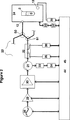
図1は、本発明の装置の好ましい態様を示す。信号増幅器29によって別々増幅される信号発生器28の番号nは、中央のボックス(又は囲み)によって表す分配ネットワーク23を介して各々のアプリケーター24の番号mに接続されている。全ての要素(又は部品)は、電源装置44及びコントローラー(又は制御装置)45に接続されていることがわかる。図1は、サンプルの並行処理を示し、発生器とアプリケーターは、分配ネットワーク、アプリケーター又はサンプルにおけるマイクロ波のエネルギーのカップリング(又は結合)に応じて制御されることが好ましい。尚、各々のアプリケーター24は、一又はそれ以上のサンプルを含むことができる。
【0054】
各々のアプリケーター24に送られるべき平均パワー(又はエネルギー)が増幅器29の最大出力パワーより小さい場合、アプリケーター24の数は、発生器28と増幅器29の数より大きくなり得、故にn<mである。各々のアプリケーター24に送られるべき平均パワーが増幅器29の最大出力パワーより大きい場合、各々のアプリケーターに対するパワーは、数個の増幅器から発生し得る。よって、いくつかの増幅器からのパワーの出力は、数個の異なるアプリケーターに分配することができる。この場合、アプリケーター24の数は、発生器28及び増幅器29の数より少なくなり得、故に、n>mである。増幅器とアプリケーターとの間の放射線のこのガイド及びカップリング(又は結合)は、分配ネットワーク23によって行われる。各増幅器とアプリケーターは、対に結合することもでき、即ち、n=mである。
【0055】
以下に、装置に含まれる個々の要素を、好ましい特徴とともに、より詳細に説明する。
【0056】
発生手段28及び増幅手段29は半導体素子(又は部品)によって本質的に構成される。300MHz〜300GHzの信号を発生できるように、数個の別個の半導体ベースの発生器が必要とされる場合がある。
【0057】
発生した信号のパワーは、0〜1Wの間で連続的に変化する。信号発生器は、信号増幅器及び/又はパワー増幅器を駆動することができる。更に、信号発生器はコントローラー45から制御することができ/プログラムすることができる。制御機能は、信号/パルスの振幅、周波数、周波数帯域幅、信号形状、パルス形状もしくは持続時間を制御する形態並びに二又はそれ以上の機能の同時の任意の組み合わせを制御する形態である。
【0058】
半導体ベースのマイクロ波発生器及び増幅器は、常套のTWT、ジャイロトロン、マグネトロンと比較して種々の長所を提供する。これらの長所を、以下に例示する:
・周波数と出力パワーの制御が容易である。
・物理的に寸法が小さい。
・高電圧が不要であり、それによって安全性と信頼性が向上する。
・ウォームアップの時間が不要であり、従って、直ちに使用できる。
・消耗部品がないので、メンテナンスコストを著しく減少でき、装置の使用可能時間を増加できる。
・TWTと比較してMTBFが非常に高く、及びMTTRが非常に低い。
・TWTと比較してゲイン・カーブ(gain curve)の平坦性がより良好である。
・TWTと比較してノイズが少ない。
【0059】
図2に示すように、増幅手段29は信号増幅器29及びパワーアンプ(又は電力増幅器)30を含み得る。信号増幅器29は、信号発生器からの信号を増幅するようになっている半導体ベースのデバイスである。増幅手段のゲインは、制御信号のレベルを変えることで調節できる。従って、出力の振幅をオペレーターが選択することができる。
【0060】
パワーアンプ30は、信号増幅器からの信号を更に増幅するために設けられる。パワーアンプも、調節可能なゲインを有する半導体ベースのデバイスである。ゲインは、制御信号のレベルを変化させることにより変化する。
【0061】
アプリケーターに適用される加熱パワーは、問題とする化学反応とサンプルの量に応じて1〜2000Wの範囲内であることが好ましい。典型的な範囲は5〜50Wのような1〜300W、30〜100Wのような10〜1000W、100〜1000Wのような50〜2000Wである。
【0062】
モニターする又は”スキャン(又は走査)する”(後述する)ために使用される電磁放射線に必要なパワーは、典型的には加熱するために必要なパワーの一部分のみである。典型的な範囲は、0.1〜10Wのような0.05〜100Wである。適用(又は照射)時間も、問題とするサンプル、プロセス(又は方法)及び化学反応に応じて変化する。典型的な反応時間は、0.2〜500秒又は0.5〜100秒のような0.1秒〜2時間である。
【0063】
増幅手段から増幅された信号は、分配ネットワーク(又は配電ネットワーク)を用いて、一又はそれ以上のアプリケーターに分配される。
【0064】
分配ネットワークは多くの特徴要素を有することができる。図2は、これらの特徴要素から抜粋したものを有する装置の態様を示す。図2は、如何にして種々の特徴要素が提供され得るかを説明する例示にすぎず、図2の特徴要素の順序は制限的なものではない。以下の特徴要素が、分配ネットワーク中に含まれ得る:
−循環器(又はサーキュレーター:circulator)31
−双方向カプラー(bi-directional coupler)32
−パワーメーター(power meter)34〜38
−擬似負荷(artificial load)33
−デバイダー(divider)51
−コンバイナ(combiner)50
−スペクトル・アナライザー(spectrum analyser)
これらのうち幾つかの特徴要素は、図2を参照しながら、以下説明する。
【0065】
循環器31はマイクロ波アプリケーター24及び分配ネットワーク23から反射されたパワーがパワーアンプ30に入ることを防ぐ。代りに、反射されたパワーは、第1パワーメーター34に必要に応じて接続された擬似負荷33に向けられる。いくつかの半導体ベースの発生器及び増幅器、例えば、シリコンカーバイド発生器/増幅器は、後方散乱マイクロ波によって影響されず、そのような発生器及び/増幅器が使用される場合、循環器31は必要ではない。
【0066】
循環器31は増幅手段と分配ネットワークの間に操作可能に接続され、少なくとも一つの入力端子(又はターミナル)、出力端子及び少なくとも一つの複合入力/出力端子(又は入力兼出力端子)を有する。入力端子は、増幅手段の出力端子に操作可能に接続されており、複合入力/出力端子は、分配ネットワークに操作可能に接続されている。更に、負荷33及び第1パワーメーター34は、循環器に関連して装置に組み込まれている。
【0067】
分配ネットワークは、双方向カプラー32のようなカプラーを含むことができ、該カプラーは、入力端子、少なくとも二つの出力端子及び複合入力/出力端子を有して成る。入力端子は、循環器又は増幅器の出力端子に操作可能に接続することができ、出力端子は分配ネットワークの他の部分に操作可能に接続することができる。
【0068】
双方向カプラーは、入力及び/又は反射されたパワーの一部を、二つのパワーメーター35及び36に向ける。第3のパワーメーター36は、アプリケーターの方向へ伝送したパワーの一部を測定し、一方、第2パワーメーター35は、反対方向、即ち、アプリケーターから離れる方向に伝送したパワーの一部を測定する。パワー測定手段は、コントローラー45に信号を送ることができる。
【0069】
並行処理を容易にするため、分配ネットワークも、コンバイナー50とデバイダー51を含み得る。これらは、スイッチを有することができ、その結果ネットワークの構造が変化し得る。
【0070】
一般に、分配ネットワークは、半導体信号発生器及び半導体増幅器をそれぞれ用いて発生させた電磁放射線及び増幅させた電磁放射線を分配するために設けられる。発生させて増幅させた信号は、単一の又は複数のアプリケーターに分配することができる。
【0071】
そのようなネットワークの例は、デバイダーを有する同軸ケーブルであり、パワー/信号のライン(又は線)を、別々のアプリケーター全てに供給するのに必要とされる数と同数のパワー/信号ラインに分割する。分配ネットワークを達成する別の方法は、導波管、ストリップ・ライン等を使用することである。分配ネットワークは、図3、4、5及び6に示すように、アプリケーターのデザインの一体的な部分で有り得る。
【0072】
24のようなアプリケーターは、種々のタイプのものが有り得る。本発明によれば、アプリケーターは、いくつかの特徴要素を含むのが好ましい。これらの好ましい特徴要素のうちいくつかは、図2を参照しながら、以下説明する。具体的なアプリケーターのいくつかについて、後でより詳細に説明する。
【0073】
アプリケーターの最低要件は、以下の通りである:
a)入力端子12、
b)サンプルホルダー1、及び
c)入力端子12からのマイクロ波エネルギーを閉じ込める手段
【0074】
サンプルに吸収される(又はアプリケーターによって反射される)パワーに応答して信号発生器及び増幅器の動作を制御するために、アプリケーター内で吸収され及びアプリケーターによって反射される全パワーの測定を行う必要がある。
【0075】
サンプルでのパワー(又はエネルギー)の吸収量を測定(又は決定)するために、アプリケーターは電磁場の強度を測定する手段を有することができる。アプリケーターは、アプリケーターから反射されたパワーを吸収する負荷33に操作可能に接続された出力端子を有することができる。更に、第4のパワー測定手段37は、負荷33及び制御手段45に操作可能に接続されている。また、ループ・アンテナ(loop antenna)13が、マイクロ波受信(又は受容)手段として機能できる。ループ・アンテナは、第5のパワー測定手段38及び制御手段45と接続されている。
【0076】
上述の負荷33及びループ・アンテナ13は、エネルギーをパワー・メーター37又は38に伝えることによって、サンプル1を経由して伝送されるマイクロ波をモニターし、受信するために使用される。サンプルにて照射されるパワーとサンプルによって伝えられ/反射されるパワーの差は、まさにそのセットアップに応じて各パワー・メーターを用いて測定され、システム内のエネルギー損失とサンプル内にて吸収されたエネルギーの合計を示す。サンプルがアプリケーター内に導入される前に、負荷の無いアプリケーターのシステム損失を測定することによって、アプリケーターを較正することができる。サンプル内で吸収されるエネルギーは、その温度と周波数にて、誘電特性に関してサンプルを特徴づける。所定の範囲、例えば、1〜4GHz内で周波数について走査し、35から反射された信号とともに負荷33又は受信アンテナ13からの信号をモニターすることによって、化学反応の進行をフォローできる。
【0077】
一又は複数のサンプルへのマイクロ波エネルギーの適用をモニターし制御するために、アプリケーターは、コントローラーに操作可能に接続されたセンサーを含むことができる。加熱する間(及びその間の中間非加熱の間)に、圧力、温度、pH、及び導電率のようなプロセス又は反応の程度を特徴づけるいずれかのパラメーターを測定するセンサーを含むことができる。マイクロ波のキャビティ用の一つの可能な温度センサーは、国際公開WO94/24532号に記載されている。そのようなセンサーからの出力はまた、サンプルで吸収されたパワーの量の目安を与えることができる。
【0078】
スペクトル・アナライザーをパワー測定手段に接続することができ、パワー測定手段は周波数選択式で有り得る。アプリケーターに向けられた電磁信号が、時間依存性である(例えば、パルス状である)場合、サンプルに照射されたパルスの時間−周波数スペクトル及び反射された/伝えられた信号の分析は、サンプルの有用な情報をもたらすことができる。この分析は、測定された信号のフーリエ変換を含み得る。この特徴要素はアプリケーターに特に結合しているわけではなく、むしろ、コントローラーに含まれ得る分析手段と、システム内の種々の位置のパワーメーターの測定の組み合わせである。
【0079】
アプリケーターは調節可能であることが好ましく、使用される周波数に応じて、サポート・モード(support mode)に合せることができる。アプリケーターは、準静(quasistatic)、近距離場(near field)、表面場(surface field)、シングル・モード・キャビティ(single mode cavity)又はマルチ・モード・キャビティ(multi mode cavity)に加え、開口・キャビティ(open ended cavity)を有することに留意すべきである。アプリケーターのある幾何学的な(又は構造的な)パラメーター(例えば、共振器のロッド)を調節することによって、共振周波数を入力端子12に接続された信号の周波数に一致させるようにアプリケーターを調節することができる。
【0080】
サンプル1をアプリケーター内に直接的に配置することができるが、サンプルは典型的には、開放した又は閉じたサンプルホルダー2内に配置される。そのようなサンプルホルダーは、アプリケーターの一体的部分であり得、あるいはマイクロ波加熱用途にて使用する適切ないずれかの物質から成る別の反応容器であり得る。当業者によく知られているように、サンプルホルダーを構成する物質(又は材料)はマイクロ波エネルギーを好ましくは吸収するべきではない。種々のタイプのポリマー及びガラスを使用できる。複数のサンプルを同時に加熱する場合、特に、種々のタイプのトレイ、マイクロタイター・プレート(microtiter plate)等が好ましく使用され得る。複数のサンプルホルダーをサンプルホルダーセットに組み込むことができ、そのようなセットアップは、全てのサンプルを同時に非常に均一に加熱することを可能にする。
【0081】
サンプルホルダーには、プロセス工程とプロセス工程との間もしくは全プロセスと全プロセスとの間、又はプロセス工程もしくは全プロセス工程の間中に、アプリケーター及びサンプルホルダーの内外へサンプルを移動するためのサンプル入口及び出口部分を更に設けることができる。
【0082】
気体とサンプルとの間で反応することを防ぐために、アプリケーター内の自由空間を不活性気体で満たすことができる。しかし、サンプルホルダーはフタを有することが好ましい。アプリケーターは、サンプル上の空間に不活性な雰囲気を供給するための少なくとも一つの入口/出口を有することが好ましい。別法では、サンプル上の空間を、反応性の気体、例えば、水素化反応に有用なH2で満たす。
【0083】
アプリケーターは、化学反応によって生ずる又は反応パラメーターとして高圧雰囲気を与えるために意図的に形成された高い内圧に耐え得るべきである。高い内圧は、通常、液相の沸点を超えるようにサンプルの温度を上昇させる方法として使用される。圧力を予め定めたレベルに保ち、又は超える又はすべきでないレベルに予めセットすることができる。圧力システムは、加圧される部品の保護と人の安全のために安全バルブ機能を組み込んでいる。
【0084】
サンプルの急速冷却は、きわめて実際的な特徴要素であり、アプリケーター内に装備され得る。即ち、冷却手段を全く使用しないでサンプルを冷却する場合、サンプルが周囲の温度に達するまでの時間は、通常きわめて長時間であり、望ましくない副反応や他の好ましくない現象を引き起こす。従って、サンプルが予め定めた温度に達するのに要する時間を最小にするために、強制的な冷却を使用することができる。冷却装置は、例えば、空気の循環、水もしくは他の液体冷却媒体の循環、ペルティエ素子等のいずれのものでもよい。冷却装置もプロセス・サイクルの間中、温度を制御するために使用することができる。冷却装置の一つの重要な用途は、サンプルの温度サイクルが望ましい場合である。予めプログラムされた温度サイクルを使用して、マイクロ波を用いるサンプルの加熱及び冷却装置を用いるサンプルの冷却を制御する。そのような適用の例は、PCR反応(ポリメラーゼ連鎖反応:Polymerase Chain Reaction)を行うための温度サイクルである。
【0085】
コントローラー45は、図2に示すように中枢機能(central function)を有している。コントローラーは、装置とその全てのモジュール/部品の制御(ランタイム・コントロール:run-time control)及びプログラム化のためのコンピューターベースのシステムである。
【0086】
ユーザー・インターフェイスとして、及び/又は1台または数台のマイクロ波装置用のコンピューティング・デバイスとして、ネットワーク内で1台または数台のPCにコントローラー45を接続してもよい。このようにすると、データ及び/又は処理されたデータ及び/又は予め定めたプロセスパラメーターに関するデータを保存する記憶手段が利用可能となる。
【0087】
コントローラー45によって発生手段28に供給される制御信号は、アプリケーター24から後方反射された信号又は伝送された信号の第1関数に従って変化し、該後方反射された信号又は伝送された信号は、パワー測定手段34〜38の一つによって検知される。コントローラーによって増幅手段29及び30に供給される制御信号は、アプリケーターから後方反射された信号又は伝送された信号の第2関数に従って変化し、該後方反射された信号又は伝送された信号は、パワー測定手段34〜38の一つによって検知される。
【0088】
発生手段28に供給される制御信号は出力周波数を決定し、増幅手段29及び30に供給される制御信号は増幅される信号の振幅を決定する。増幅される信号の振幅は、時間の関数として変えることができる。
【0089】
制御システムは3種類の操作モードを有する:
1)加熱モード
2)モニタリングモード
3)プログラミングモード。
【0090】
加熱モードにてコントローラー45を操作することは、コントローラーの構成に特別な要件を課する。コントローラーは、信号増幅器29及びパワーアンプ30からの出力パワーを設定し制御することができる。更に、コントローラーは、信号発生器28によって発生させられた信号を変調することができ、方形波又は三角波のような時間の関数である、出力信号を発生させることができる。同じ意味において、信号のデューティー・サークル(duty circle)は、伝送される信号のパワーを減少するために調節可能でなければならない。
【0091】
上述の特徴は、信号増幅器29に第1制御信号を適用し、パワーアンプ30に第2制御信号を適用することによって提供される。
【0092】
コントローラーに組み込まれていなければならない他の特徴は、信号発生器の出力周波数を制御する能力である。周波数走査に関するセッティング、即ち、開始(又は出発)周波数、停止周波数、周波数の分解能及び走査時間もコントローラーから操作可能でなければならない。開始周波数は0.5〜300GHzの範囲内であり、1〜30GHzの範囲内であることが好ましい。その間で電磁放射線の周波数が変化する予め定められた値は、0.5〜300GHzの範囲内にあり、1〜30GHzの範囲内にあるのが好ましい。
【0093】
更に、プロセス全体、又はプロセスが一よりも多い工程を伴なう場合、プロセスの一部のためのプロセス時間は、制御可能でなければならない。
【0094】
アプリケーターへの入力パワーの測定はパワーメーター36を用いて行われるが、パワーメーター36の最適な位置は、分配ネットワークのまさにその構成に応じて決定される。同様に、アプリケーターから反射されたパワーは、パワーメーター34又は35で測定され、パワーメーター37又は38は、アプリケーターから結合して出たパワーを測定する。アプリケーターで吸収されたパワーは、アプリケーター内の損失を測定するためにキャビティが空である装置を較正することによって、測定することができる。この較正は、サンプルが処理される周波数の範囲内で行うことができる。反射されたパワーと空のアプリケーターのパワー損失を差し引くことによって、吸収されたパワーを計算することができる。
【0095】
パワーメーター34〜38によって測定されたパワー信号は、コントローラーに送られ、信号発生器28の周波数及並びに/又は信号増幅器29及び/もしくはパワーアンプ30のゲインを制御するために使用される。
【0096】
コントローラー45はまた、方向性カプラー32、循環器31のようなシステムの部品(又は要素)に制御信号を提供し得る。コントローラーは他のタイプの信号処理を提供することができる。コントローラーは、上述したセンサーを用いて、温度、圧力、pH、電導率等のようなサンプルパラメーターを制御しモニターすることができる。そのようなパラメーターの最新の値を測定することによって、コントローラーは、パラメーターが予め定めた値に達する場合に応答できる。プロセスの間に超えるべきでない最大値、及びプロセスの間に下まわるべきでない最小値をセットすることができる。
【0097】
電磁放射線とサンプルの結合(又はカップリング)を測定し、放射線の周波数とパワーを変えることは、必須である。更に、電磁放射線の周波数を、予め定めた閾値を超えるフィードバック信号のレベルの変化に応じて変えることができる。反射率として測定される、電磁放射線とサンプル1の間の周波数とカップリング効率に関するデータを、更なるプロセス(又は処理)のためにメモリーに保存することができる。
【0098】
モニタリングモードでは、スキャン機能が利用でき、スキャン機能は(狭いベースラインを与える)第1スキャンからの信号を規格化し、多くの次のスキャンサイクルの間、規格化したベースラインとの差を検出する。サンプル1で吸収される最大パワーを与える周波数をトラッキングし、これにロックすることは(最大値を動かすことは)、他の利用可能な特徴である。マイクロ波発生器28の周波数は、中心周波数付近から少なくとも±30%の範囲で調節可能である。
【0099】
装置がプログラミングモードで作動する場合、内蔵の高レベルの方法プログラミング言語を使用して、創作し、保存し、取り出し、編集する可能性を、オペレーターが利用できるようにしなければならない。方法は、予めプログラムされた事象のシーケンスであり、各々の事象はインプットとして少なくとも一つのプロセスを有する。プロセスパラメーターは、例えば、パワー、時間、圧力等である。
【0100】
装置はまた、全てのプロセスデータを収集し処理する方法を含むことができ、内部及び/又は外部データベースからの該データを保存し及び/又は取り出すことができる。
【0101】
変数である下記のパラメーター:
周波数、波形、パワー、時間、温度、圧力、人工的雰囲気
の少なくとも1つと組み合わされた該モニタリング及び制御手段を有する装置を用いることによって、該化学反応のためのこれらの最適の条件を最適化し、維持することが可能である。
【0102】
再び図2を参照して、マイクロ波で補助される化学及び生物学的反応用装置を説明する。装置の主な特徴の1つは、該化学反応の反応条件を最適化することを目的とする。装置の他の特徴の組は、該化学反応の最適化された条件をモニターし、制御することを目的とする。更に、他の特徴の組は、プロセスデータを収集し、データの処理をし、内部及び/又は外部データベースからデータを保存し、取り出すことを目的とする。
【0103】
二以上の出発物質が化学的に反応する場合、それらの物理的及び化学的性質は変化する。これらの性質の変化は、通常温度に依存する。化学反応は、反応速度を速くするために、又は反応を開始させ維持するに十分なエネルギーを供給するために、しばしば昇温して行われる。供給されるエネルギーの形態は、熱放射線、超音波、マイクロ波等であってよい。供給されたエネルギーの形態がマイクロ波である場合、反応物質内に伝えられるエネルギーは、出発物質及び化学反応の間に形成された物質の誘電性に依存する。誘電性は温度依存性であり、従って化学的プロセスの間に変化する。誘電性の変化は化学反応中に新しい物質が形成することによっても起こる。物質の誘電性は周波数とともに変化することも既知である。
【0104】
周波数同調(又はチューニング)をともなう装置では、反応に結合されるエネルギーの最適値は、特定の周波数にて生ずる。この周波数は、サンプルの誘電率ε’の温度依存に従って、反応の温度によって変化するであろう。
【0105】
”化学反応”という用語は、二つの原子間の(共有)結合の形成又は開裂を伴なういずれかの無機及び有機反応に加え、クラスター及び大きな分子の同様の反応をも意味するものである。この用語はまた、例えば、ポリメラーゼ連鎖反応(PCR)及びそれと同様のタイプの反応である、酵素が触媒として関与する反応も含むことを理解するべきである。化学反応は、有機化合物、即ち、低分子有機化合物及び生物学的な有機化合物(例えば、酵素)を伴なう反応であることが好ましい。更に、一以上の有機化合物の化学構造の転化が起こるのが好ましい。
【0106】
化学反応は、一般的には有機化学反応であり、そのうちの実質的に全ての既知の反応が適用可能である。代表的な反応のタイプは、重合/オリゴマー化、エステル化、脱炭酸、水素化、脱水素化、1,3−双極性付加のような付加、酸化、異性化、アシル化、アルキル化、アミド化、アリール化(arylation)、マレイン化(maleinisation)及びフマル化(fumarisation)等のディールス−アルダー反応、エポキシ化、ホルミル化、ハイドロカルボキシレーション(hydrocarboxylation)、ハイドロボーレーション、ハロゲン化、水酸化、ハイドロメタレーション(hydrometallation)、還元、スルホン化、アミノメチル化(aminomethylation)、オゾン分解等である。本発明の装置及び方法は、一以上の触媒を伴なう反応及び不斉(又は非対称)有機反応に、特に適すると考えられる。
【0107】
化学反応は、適当な溶媒中にて、又はニートの形態にて起こり得る。溶媒を使用する場合、誘電正接(又は損失正接:loss tangent)は、室温にて約0.04より大きいことが好ましい。適切な溶媒として、アセトニトリル、DMF、DMSO、NMP、水、tert−ブタノール、エタノール、ベンゾニトリル、エチレングリコール、アセトン、THFを例示できる。発生した電磁信号の周波数は、使用する溶媒の吸収バンド/ピーク(band/peak)に調節することができる。
【0108】
化学反応は、一般に出発物質(基質又は”化学種”)、試薬、及び必要に応じて触媒(例えば、熱に安定なDNAポリメラーゼのような酵素)を必要とする。出発物質は、固相、液相又は気相のいずれかの相のいずれかの化学物質であってよい。出発物質には、例えば、化学反応中の反応物の固体の担体(又は支持体)として使用される全ての物質を含む。出発物質は、化学反応中に形成される全ての物質(化学物質)も含み、同じ装置内にて行われる新しいプロセスにおける新しい出発物質又は同じプロセス中の次の化学反応に対する新しい出発物質であると考えることができる。出発物質又は試薬も人工的雰囲気の気相中に含めることができる。装置内で行われた先の化学反応の最終的な化学生成物は、装置内で行われる次の化学反応の出発物質であると考えられよう。
【0109】
アプリケーター24は、一又は複数のサンプル1にマイクロ波エネルギーを適用するために一つ又は複数のキャビティ(又はキャビティ)を有して成る。種々のタイプのキャビティ及びキャビティの配置(又はアレンジメント)は、本発明の装置のアプリケーターの種々の態様を表すことを理解するべきである。原則として、装置はいずれの既知のタイプのアプリケーター(成功には種々の程度があるが)を有してもよいので、本発明は、特に記載した態様に制限されることはない。以下に、種々のアプリケーターのデザイン及び並行処理の程度を示す種々の態様を記載する。これらの態様は、図1及び2に関するアプリケーター24として、作用し得る。
【0110】
図3は、アレイ(array)に配置された幾つかのキャビティを示す。このアレイはマイクロタイター・プレート(microtiter plate)4であり得るが、それに制限されるものではない。各々のキャビティはフタ6、底プレート8及び外側金属管17によって規定される。各々のキャビティは、サンプルホルダー2、キャビティの共振周波数を調節するための共振器ロッド16、入力及び出力信号のループ・アンテナ18、及び必要であれば気体の入口/出口15を有して成る。マイクロ波は、図3に示すように、ループ・アンテナ18を通って誘導的に導入され、また別法では、全てのアレイに供給する分配ネットワークを介して容量的に導入することもできる。サンプルを、キャビティの外側管17内の共振器ロッド16上に置く。共振器ロッドの長さをキャビティの共振周波数を変えるために調節することができる。全ての部品は、閉じた電気回路を形成するために互いに電気的に接続されている。キャビティを加圧することができ、人工的な雰囲気に置くことができる。
【0111】
別の応用を図4A及びBに示す。この図では、四つのサンプルウェル(又はサンプル窪み)9をサンプルホルダー・セット内に対称的に組み込まれている。キャビティ内の壁として作用する金属製の遮蔽かご3は、サンプルホルダーを取り囲んでいる。マイクロ波伝送デバイス5は、四つの各サンプルホルダーの間に規定される空間の中央に配置され、それにより四つのサンプル1を、同時に照射する。従って、図4に示した態様においては、幾つかの(例では四つの)サンプルが並行して処理される。図4Bに示すように、複数のキャビティを、図3に関して記載したアレイと同様のアレイに配置することができる。
【0112】
図5は、伝送又は受信デバイス12又は13の各々が、底プレート8の上に配置され、これらのデバイスがアレイを形成している構成を示す。フタ6は、プレートの上端の上に配置され、受信又は伝達デバイス13又は12をフタの上に配置することができる。底プレート又はフタは、マイクロタイター・プレートであり得るが、それに制限されるものではない。底プレート8とフタ6は、金属管3と共にキャビティを規定する。適切な物質(ガラス又は、例えばポリスチレン等のポリマー)で作られた小ビンを、サンプルホルダー2として機能させるために金属管内に挿入する。冷却装置を底のプレートに取り付けることができる。吸収されなかったマイクロ波エネルギーを消散させるために、フタはマイクロ波吸収物質を含むことができる。消散したエネルギーを処理するために、冷却装置をフタにも取り付けることができる。人工的な雰囲気への入口/出口部15を、フタ及び/又は底プレートに取り付けることができる。反応容器を、人工的な雰囲気を用いて、又は化学反応により内部に発生した圧力を用いて、加圧することができる。場の閉じ込め(制限)は、12又は13にて高誘電率体を用いることで実現できる。それによりフタを取り除くことができ、アプリケーターは開口のアプリケーターとなる。
【0113】
図6は、各々のサンプルウェルについて個々のアンテナ5を有するマイクロタイター・プレートを示し、アンテナは、サンプルウェル内に浸漬されている。サンプルウェルは、アレイに配置され、金属管3は、遮蔽物(又はシールド)として各ウェルを取り囲んでいる。ガラス又はプラスティック製のサンプルホルダー2は、通常、サンプルホルダーとして作用するように金属管3の中に挿入される。図3及び5の態様の場合のように、各々のサンプルは、個々に処理される。
【0114】
マイクロ波を用いる処理に対する一般的な指針及び指示並びにマイクロ波のキャビティの構成は、例えば、ガブリエルらの、ケミカル・ソサイエティ・レビュー、1998年、第27巻、第213〜223頁(Gabriel, et al., Chem. Soc. Rev, 1998, Vol. 27, pp 213-223)、及びハービーの編集によるマイクロウェーブ・エンジニアリング、アカデミック・プレス、ロンドン1963年(Microwave Engineering, Harvey (ed.), Academic Press, London 1963)(特に第4〜6章)に記載されている。
【0115】
本発明の装置は、少なくとも一つの有機化合物を含んで成る少なくとも一つの反応混合物(サンプル)を、加熱するのに適している。反応混合物又は各々の反応混合物(サンプル)は、更に、一又はそれ以上の試薬及び必要であれば触媒(例えば、酵素)を含むことができる。
【0116】
特に興味深い態様では、装置は二又はそれ以上の反応混合物を同時に又は逐次的に又は断続的に加熱するようになっている。
【0117】
本発明の一つの重要な態様では、複数の化学反応を並行して行う。これは、本発明の装置がコスト効率のよい構成であるために現実的である。図1は、複数のサンプルの並行処理を指示する原理を示す。
【0118】
本発明は、上述した本発明の第三の要旨に従って、複数の化学反応を同時に又は逐次的に行う方法をも提供する。
【0119】
この方法及び以下の方法は、ここに規定した装置を用いて行うことで、全て適切に行われる。
【0120】
電磁放射線を(例えば、周波数、加熱時間、パワー、信号のパルシング、信号のサイクル等に関して)サンプルの各々に適合させ得るという事実は、例えば、プロセスを最適化する場合、及び化合物のライブラリーを構成する場合、重要である。後者の場合、種々の試薬と種々の基質(及び酵素)の範囲内で、反応性が相違することはいずれも、装置によって補償することができる。従って、本発明の別の態様において、化合物(少なくとも四つの化合物)の組み合わせのライブラリー(combinatorial library)を作成するために装置を使用できる。
【0121】
また、化合物が組み合わせのライブラリーの一部ではない、即ち、化合物が共通の構造的な特徴を共有しない場合に、本発明の装置と方法を並行プロセスにて多数の化合物を製造するために使用できる。装置は、各々のサンプルに独立して電磁放射線の適用を結合する(又はカップルする)ことができるので、これは、並行プロセスで可能である。更に興味深い態様は、サンプル入口とサンプル出口を有するサンプルホルダーを使用することによる化合物の連続製造である。この後者の場合において、環状又はらせん状の管として形成されたサンプルホルダー内に、サンプルを入れることができ、続いてサンプル入口を通してすすぎ水を入れ、それにより、サンプル出口を通してサンプルホルダーの外にサンプルを押し出し、続いて新しいサンプルを入れる。マイクロ波加熱条件下では反応時間が比較的短いために、多数のサンプルを並行して(数サンプルのホルダー内で)又は逐次的に(一サンプルホルダー内で)処理することができる。
【0122】
プロセスパラメーター、即ち、周波数と電磁放射線のパワーに関するパラメーターは、コントローラー(45)を用いて制御される。上述した記載から理解されるように、半導体ベースの信号発生器を用いて、特に、本発明の第一の要旨にて規定した装置を用いて、電磁放射線を供給するのが好ましい。ある応用、例えば、加熱/冷却サイクルが必要な場合、電磁放射線は、断続的に適用することが好ましい。別法では、いずれかの冷却手段を、断続的に作動させることができる。
【0123】
上述したように、電磁放射線は各々のサンプルに限定的に適合させる、即ち、各々のサンプル/サンプルホルダーに対してプロセスパラメーターは独立して選択される。このことは、各々のサンプルは異なる条件下で処理されること、又はサンプルの組(又はセット)は実質的に同じ条件下で処理されるが他のサンプルの組とは異なる条件下で処理されること、又は全てのサンプルは実質的に同一の条件下で処理されることを意味する。一つの組のサンプルを実質的に同一の条件下にて処理する場合、図4に実質的に示したようなアプリケーターであって、二以上のサンプルホルダーから成るセットの中にサンプルホルダーをまとめたアプリケーターを使用することが有利であり得る(図4に四つのサンプルホルダーから成る一つのセットを示す)。そのようなサンプルホルダーのセットは、通常、2〜1000のサンプルホルダーから成り、典型的には3〜96のサンプルホルダーから成る。
【0124】
装置は、化学反応の進行と完了の表示としてデータを生成することができる。そのようなデータを、コントローラーと操作可能に連結された(又は連動させた)データベース内に保存することができる。更に、化学反応により生じる生成物に関する情報、例えば、純度、エナンチオ純度、収率等をデータベースに供給することができる。複数の反応混合物を同時に別々のキャビティ内にて種々の条件(例えば、周波数、加熱時間、加熱サイクル、加熱パワー、試薬、基質及びいずれかの触媒の濃度、信号の形状、反射されたパワー、伝送されたパワー、温度、圧力、人工的な雰囲気、サンプル小ビン(又はバイアル)のタイプ等に関する条件)下にて加熱する場合、又は同じもしくは別のキャビティ内にて別の条件下にて逐次的に加熱する場合、そのようなデータは、適切な分析(例えば、自動的な統計的な分析)の後、その後の同様な化学反応の反応条件を最適化するという独特な可能性を提供するであろう。処理されたデータは、適切な分析方法を用いて分析することができ、最適なパラメーター設定と条件を見出すために評価することができる。プロセスの結果を、最適化のために多変数データ分析(multi-variant data analysis)によって処理することができる。
【0125】
更に、例えば、特定の種類の触媒を使用する置換反応、特定の基質を使用するディールス−アルダー反応等の同じタイプのその後の反応のために適切な反応条件の一つのセットを提供することが可能である。
【0126】
本発明の更なる展望では、多数の標準的なタイプの反応について最適な(又は適切な)プロセスパラメーターに関するそのようなデータを、装置の供給者は明らかにすることができ、本発明の装置とともに提供することができると考えられる。従って、好ましい態様において、コントローラーと接続した記憶手段は、予め定めたプロセスパラメーターに割り当てられたセクション(又は部分)を含む。そのようなセクションを、装置の供給者が定期的に更新して、装置の利用者に提供できる置き換え可能なメモリーカード(又は”スマートカード”:Smart Card)として形成することができる。
【0127】
結果的に、本発明は上述した方法及び使用に関し、当該方法アプリケーター内のサンプルに供給された電磁放射線の周波数、伝送されるパワーのレベル及び電磁放射線の適用時間は、問題とする化学反応について予めセットされた値によって決められ、そのような予めセットされた値は装置のコントローラーと結合した記憶手段内に保存される。
【0128】
ゆえに、第9の要旨として上述した更に興味深い要旨、本発明は、必要であれば触媒の作用の下で、化学種を試薬と化学的に反応させるためのキットであり、化学反応を、本発明の第1の要旨にて規定した装置内にて行うキットである。
【0129】
第9の要旨において、キットに設けられるサンプルホルダーは、一又はそれ以上の必要な試薬及び/又はいずれかの適切な触媒を含むことができ、その結果、使用者(又はユーザー)は、サンプルホルダーに化学種を供給することのみを要する。(もし溶媒が必要であり又は望ましいのであれば)溶媒もキットに供給して試薬と触媒が十分に溶解/分散することを確保することが好ましい。別法では、サンプルホルダーは、化学反応の生成物の分離を容易にするために、固定化された形態の試薬及び/又は触媒を含むことができる。
【0130】
装置は、化学反応を行うための多数の他の有用な方法を行うことを可能にする。一つの態様において、反応の進行は、電磁放射線の適用の(反射率の基準(又はレフェレンス)のセット)前及び後にサンプルを走査することによって同時にモニターされる。加熱の後及び前(基準のセット)の反射率のセットを比較することによって、進行を測定することができる。レファレンスの状況(アプリケーターは空)とサンプルがアプリケーター内に入れられている状況との間でマイクロ波信号を比較することは、米国特許第5,521,360号に記載されている。本発明に関して、コントローラー(45)を用いて、反射率の測定されたセットに対応してプロセスパラメーターを変えることが可能である。好ましくは、カップリング効率のセットを、比較の前に標準化し及び/又は置き換えることができる。
【0131】
従って、本発明は上述の本発明の第3の要旨に従って化学反応を行うための方法を提供する。
【0132】
上述の方法の一つの興味深い変形例(”バイオセンサー”変形例)として、周波数の第1(参照)変化(工程(b))(”走査”)は、サンプルに化学物質を入れる前に行われる。サンプルは、酵素又は生体分子又は細胞を含んで成ることができ、そのための化学物質は基質又はリガンドである。その後、引き続き走査が行われ、反射率の差は、化学物質とサンプルの成分との間の相互作用を反映することが予想される。この態様は、リガンド/基質及び酵素間の相互作用を研究するための特に興味深い変形例となり得る。この変形においては、加熱(工程(c))は、しばしば省略される。更に、工程を繰り返すことは、時間をかけて上述した相互作用を研究するためにのみ必要であり、さもなければ反射率の二つのセットの比較のみが必要であろう。
【0133】
更に、本発明は、(特に、予め定めた範囲が電磁放射とサンプルの間の最適のカップリングを与える周波数を含んで成る場合)電磁放射線の適用に関して反射の最小値(又は二もしくはそれ以上の最小値)を確認するための方法も提供する。即ち、本発明は上述した本発明の第5の要旨の化学反応を行う方法を提供する。
【0134】
本発明は、化学反応を行いながら、局所的な(又は全体的な)反射率を示す周波数を求める方法、即ち、上述の本発明の第6の要旨の化学反応を行う方法も提供する。
【0135】
更に、本発明は、化学反応を行いながら、反射率が予め定めたレベルを有する周波数を求める方法、即ち、上述の本発明の第7の要旨の化学反応を行う方法を提供する。
【0136】
ここに記載した方法の特に興味深い変形例においては、各々のサンプルは、少なくとも一つの酵素を含み、更に、各々のサンプルはPCR混合物である変形である。
【0137】
装置は、適用されるエネルギー(その結果PCRの小ビンの温度)を正確に変化させ、パルス化するので、PCR反応は、本発明の第六の要旨の装置に関する特に興味深い応用である。更に、装置は、PCR反応の進行を制御し、モニターする手段を有して成る。
【0138】
PCR技術は、米国特許第4,683,202号及び米国特許第4,683,196号に、概ね記載されている。PCR混合物を加熱するためにマイクロ波放射適用を使用することは、国際公開公報WO91/12888号、WO95/15671号及びWO98/06876号により既知であるが、本発明の装置を使用して処理することは、既知のシステムと比較して新規な効果をもたらす。PCR混合物を取り扱い、処理するための一般的な指針(例えば、温度範囲、サイクルの回数及び時間)は、国際公開公報WO98/06876に見ることができる。PCR用の温度サイクルの典型例は、80〜100℃付近(例えば、0.5〜3分間)までの変性加熱工程、混合物を20〜40℃付近(例えば、0.1〜1分間)とする冷却工程、及び55〜75℃付近(例えば、1〜5分間)の重合工程である。完全な増幅反応には、15〜100サイクル、例えば、約25〜35サイクルが必要である。
【0139】
本発明によれば、エネルギーの適用を非常に正確に制御すること、制御可能な線量でエネルギーを適用すること、及びサンプルを極めて迅速に冷却して、冷却工程を減らすことができる。更に、(ある基準に対する)反応の終了を決定するために、例えば、各々の冷却工程にて、反応混合物に低強度のマイクロ波信号を適用することによって、反応の進行をモニターすることも可能である。従って、少なくとも各々のサイクルの一部の間にサンプルが冷却される少なくとも二つのレベルのサイクルにて電磁放射線を当てるのが好ましい。少なくとも二つのレベルは、80〜100℃及び55〜75℃の温度レベルを表すことができる。通常、20〜40℃の温度レベルに達するために冷却を開始する。急な冷却勾配を得るために、(例えば、コールドブロック(ボトムプレート)の形態にて)、絶えず冷却することができる。
【図面の簡単な説明】
【図1】 図1は、本発明の装置内の主な3つのモジュールの可能な組み合わせを示す。
【図2】 図2は、本発明の装置を含む態様を示す。
【図3】 図3は、マイクロタイター・プレート内に取り付けられたアプリケーターを示す。
【図4】 図4は、四つのウェルの中央に対称に配置されたマイクロ波の導体を有するマイクロタイター・プレートを示す。
【図5】 図5は、入力部12及び出力部13を有する、伝送タイプのアプリケーターを有するマイクロタイター・プレートを示す。
【図6】 各々のサンプルのウェル用の個々のアンテナを有するマイクロタイター・プレートを示す。[0001]
The present invention relates to an apparatus for heating a chemical reaction mixture. In particular, the present invention relates to an apparatus that utilizes one or more semiconductor-based microwave generators, making the apparatus suitable for parallel processing (or parallel processing) of chemical reaction mixtures. May include, for example, a method of heating multiple samples simultaneously or sequentially (or continuously), a method of monitoring (or monitoring) a microwave heated chemical reaction, and a frequency and applied power (energy or The present invention relates to a method for performing a chemical reaction, such as a method capable of determining an optimum condition for electric power).
[0002]
One of the major obstacles for organic chemists today is the time consuming search to obtain an efficient route for organic synthesis. As an example, in the pharmaceutical industry, the average capacity of tens of years ago per chemist per year is about 25-50 full substances, so that the same number of potential new drug candidates I got a new chemical. Today, the number is several hundred per year and is expected to soon be in the thousands of years.
[0003]
Therefore, the challenge for pharmaceutical industry and organic chemists is to identify time-saving methods in drug development, identify methods to create chemical diversity, develop new synthetic pathways, and possibly traditional “impossible” synthesis Includes reintroduction of routes. Reaching a completely new chemical species is a constant challenge.
[0004]
As will be apparent from the following, microwave assisted chemistry is a method that avoids at least some of the problems described above:
・ Speed up the reaction time by several orders of magnitude,
-Improving the yield of chemical reactions,
Providing a higher purity reaction product by heating quickly, thereby avoiding impurities from side reactions, and
・ Responding to reactions not possible with conventional thermal heating technology
I will provide a.
[0005]
Microwave-assisted chemistry has been used for many years. However, the apparatus and method are largely based on conventional household microwave ovens (or microwave ovens). A home microwave oven has a multi-mode cavity (or cavity) and energy is applied at a fixed frequency between 915 MHz and 2450 MHz (which depends on the country). The use of single mode cavities has also been reported (see, eg, US Pat. No. 5,393,492 and US Pat. No. 4,681,740).
[0006]
The market for microwave generators is entirely dominated by magnetrons. In some situations, a traveling wave tube (TWT) is used to amplify the microwave signal. There are several problems with conventional devices. Some of these are described below.
[0007]
There is a problem that the energy distribution in a conventional microwave oven is non-uniform. This leads to different sample temperatures depending on the position of the sample in the oven. Furthermore, a non-uniform energy distribution makes it difficult to obtain reproducible results. This effect is particularly striking when using sample holder arrays (or arrays) such as microtiter plates (eg, having 96 wells). Even if the sample is rotated in the oven, the reproducibility is not improved so much.
[0008]
In conventional systems, the power delivered to each sample in the sample array (or array) is calculated as the average power per sample by dividing the measured input power by the total number of samples. Can only do. Due to the non-uniform energy distribution inside the cavity, this calculation only gives an approximation for the power applied to each sample.
[0009]
One way to control the reaction is to monitor the pressure and temperature for all each well (or well). This can provide status information within a particular well during a particular reaction. Changing the position will produce different results and reproducibility will be insufficient. Another way to try to obtain a uniform energy distribution is to place a large load in the cavity in order to absorb energy more uniformly.
[0010]
Single mode cavity resonators offer the possibility of a highly efficient and controlled heating pattern at small loads. However, the dielectric characteristics of the load vary considerably depending on the temperature, and a microwave oscillator with a constant frequency is used, resulting in a large change in power absorption. This makes it difficult to predict the process.
[0011]
Furthermore, the problems of conventional systems are usually related to the fact that a magnetron provides only a small adjustment near a constant frequency or the center frequency of the magnetron. In addition, magnetrons exhibit unpredictable behavior and are very sensitive to temperature, especially when their efficiency decreases as they approach the end of their “life”.
[0012]
TWT has been used as a variable frequency amplifier. However, TWT is quite expensive and often complicated to use. Furthermore, the TWT requires time to warm up before use. This means that the TWT cannot be switched on / off quickly. Furthermore, TWT wear is associated with high maintenance costs.
[0013]
Both magnetrons and TWTs require a high voltage power supply, which is problematic in terms of complexity and danger.
[0014]
U.S. Pat. No. 5,521,360 discloses a variable frequency heating apparatus for supplying microwaves into a furnace cavity. This device comprises a voltage controlled microwave oscillator, a voltage controlled preamplifier (preamplifier) and a power amplifier (or power amplifier). The power amplifier may be a TWT. The TWT is operably connected to the furnace cavity. The power supplied to the furnace is determined by measuring the power reflected from the furnace using a power meter. When a sample (or specimen) is placed in a cavity furnace, power can be coupled to the sample and change the temperature of the sample.
[0015]
The system described in US Pat. No. 5,521,360 has, for example, the above-mentioned problems with TWT as a drawback.
[0016]
Further limitation to use with only one cavity furnace, ie, the inability to parallel heat multiple samples using different heating parameters, is further described in US Pat. No. 5,521,360. This is a problem of the device described in the issue.
[0017]
It is an object of the present invention to provide an apparatus comprising a first semiconductor-based electromagnetic generator and a first applicator for holding a sample (or specimen), wherein the apparatus can control and heat the sample. Another purpose.
[0018]
Another object of the present invention is to provide an apparatus capable of performing parallel processing (or parallel processing) of many samples by individually setting process parameters such as frequency, power, temperature, and pressure. .
[0019]
Yet another object of the present invention is to provide an apparatus which can monitor many samples in parallel by individually monitoring process parameters such as frequency, power, temperature and pressure.
[0020]
Yet another object of the present invention is to provide an apparatus that can control many samples in parallel by individually adjusting process parameters such as frequency, power, temperature, pressure and the like.
[0021]
Yet another object of the present invention is to provide an apparatus that can uniformly heat a sample using various applicators.
[0022]
Yet another object of the present invention is to provide an apparatus capable of changing the frequency of energy applied (or applied).
[0023]
Yet another object of the present invention is to provide an apparatus that can evaluate and separate thermal and chemical effects on the electromagnetic absorption capability and behavior of a sample.
[0024]
Still another object of the present invention is to provide an apparatus capable of measuring the temperature in the reactor by monitoring the change in the resonance frequency (or resonance frequency) of the second substance placed in the reaction chamber. It is. This material may be a crystal, semiconductor, or any other solid material whose resonance frequency is temperature dependent.
[0025]
The above objective is accomplished in a first aspect by providing an apparatus for supplying electromagnetic radiation to a first applicator, the apparatus comprising:
a) first generating means for generating electromagnetic radiation;
b) first amplifying means for amplifying the generated electromagnetic radiation;
c) means for guiding (or guiding or guiding) the amplified electromagnetic radiation to the first applicator; and
d) Means for controlling the first generating means and the first amplifying means.
A device comprising:
The generated electromagnetic radiation includes a plurality of frequencies, and the first generating means and the first amplifying means are devices composed essentially of semiconductor elements (or components or elements).
[0026]
Essentially composed of semiconductor elements means that the elements that generate electromagnetic radiation, for example, the required power transistors are semiconductor-based (or semiconductor-based) power transistors. means.
[0027]
In this specification, the guide means is any means capable of guiding (or guiding) electromagnetic radiation such as a cable such as a coaxial cable or a waveguide (or waveguide) or a metal channel. Should be interpreted. The guide means may be active and / or active such as, for example, couplers, dividers, splitters, combiners, isolators, power meters, pseudo loads, spectrum analyzers, etc. Or it can also have a passive component.
[0028]
For parallel processing of a plurality of samples, the apparatus comprises a second applicator and suitable guide means for guiding at least a portion of the amplified electromagnetic radiation to the second applicator. In general, it may be advantageous to be able to supply electromagnetic radiation having different frequencies to the first and second applicators. Accordingly, the apparatus may include second generation means for generating electromagnetic radiation having a plurality of frequencies, and second amplification means for amplifying the electromagnetic radiation generated by the second generation means. In order to supply electromagnetic radiation of a plurality of frequencies, the second generating means and the second amplifying means are preferably constituted by a semiconductor element (or component) such as a semiconductor-based power transistor. An example of such a power transistor is a silicon carbide power transistor. Obviously, the same type of transistor can be used in the first generating means and the first amplifying means.
[0029]
In order to increase the flexibility of the device, the guide means may comprise means for guiding the electromagnetic radiation amplified by the second amplification means to the second applicator. Furthermore, the guide means may further comprise means for guiding at least a part of the electromagnetic radiation amplified by the second amplification means to the first applicator.
[0030]
Furthermore, in order to increase the flexibility of the device, the guide means may comprise means for switching (or switching) the electromagnetic radiation amplified by the first amplification means between the first and second applicators. Further, the guide means may comprise means for switching the electromagnetic radiation amplified by the second amplification means between the first and second applicators.
[0031]
The first and second applicators may be of various types. The first and second applicators are from quasistatic, near field, surface field, single mode cavity and multi mode cavity applicators. Preferably it is selected from the group consisting of:
[0032]
The frequency of the electromagnetic radiation generated by the first and second generating means can change according to the first and second control signals, respectively. These first and second control signals can be supplied by the control means. Similarly, the amplification of the first and second amplification means can vary according to the first and second control signals, respectively. These signals can also be supplied by the control means. The control means may comprise a general purpose computer. Such general purpose computers may form part of a neural network.
[0033]
The frequency of the electromagnetic radiation generated by the first and second generating means is in the range of 300 MHz to 300 GHz, such as in the range of 0.5 to 3 GHz or in the range of 50 to 100 GHz.
[0034]
In the second aspect of the present invention, the present invention relates to a method for performing a plurality of chemical reactions simultaneously or sequentially (or continuously),
a) supplying a first sample (or sample) into the first applicator;
b) supplying a second sample into the second applicator; and
c) applying (applying or irradiating) the electromagnetic radiation having a frequency in the range of 300 MHz to 300 GHz for a predetermined time simultaneously or sequentially (or continuously) to the first and second samples;
It is a method including.
[0035]
Electromagnetic radiation can be supplied specifically and independently for each sample. Furthermore, the applied electromagnetic radiation may have one or more pulses. Samples may be collected in a set (or set) having at least two holders. The sample itself may be a PCR mixture. While exposing the sample, the electromagnetic radiation may be applied in a cycle of at least two steps in which the sample is cooled during at least a portion of each cycle.
[0036]
The electromagnetic radiation is preferably supplied using the apparatus of the first aspect of the present invention.
[0037]
In a third aspect, the present invention relates to a method for conducting a chemical reaction, the method comprising:
a) supplying a sample into the applicator;
b) Applying electromagnetic radiation to the sample at a first level of power (energy or power) for a predetermined first time, and setting the frequency of the electromagnetic radiation to two predetermined values with a predetermined resolution. Determining the reflectance of the electromagnetic radiation from the sample at at least some (two) frequencies included in the range of two predetermined values by varying between and measuring the level of the feedback signal, Obtaining a first set of reflectivity by
c) changing the physical and / or chemical properties of the sample;
d) applying electromagnetic radiation to the applicator at a second level of power, changing the frequency of electromagnetic radiation between two predetermined values with a predetermined resolution, and the range defined by the predetermined value is: b) samples at at least some (two) frequencies included in the range defined by the predetermined value in step and included in the range of two predetermined values by measuring the level of the feedback signal Determining the reflectivity of electromagnetic radiation from, and thus obtaining a second set of reflectivity, or
e) Steps c) and d until the difference in reflectance calculated as a mathematical difference (subtraction) between the frequencies associated with the first and second sets of reflectance is within a predetermined range. ) Repeat step
It is a method including.
[0038]
Step c) may comprise applying electromagnetic radiation to heat the sample. Alternatively or additionally, the sample may be cooled and / or reagents may be added to the sample. Also, step e) is no longer applicable if the difference in reflectivity is within a predetermined range after first performing steps c) and d). Furthermore, if the difference is close to a predetermined range, performing step e) is not economical and step e) may be omitted.
[0039]
In a fourth aspect, the present invention relates to a method for performing a chemical reaction, the method comprising:
a) supplying a sample (or sample) into the applicator;
b) applying electromagnetic radiation having a starting (or starting) frequency to the sample;
c) changing the frequency of the applied electromagnetic radiation between two predetermined values with a predetermined resolution;
d) determining the reflectivity of the electromagnetic radiation from the sample by measuring the level of the feedback signal during at least a portion of changing the frequency of the electromagnetic radiation;
e) determining the frequency of the electromagnetic radiation whose reflectivity is within a predetermined range from the level of the feedback signal
It is a method including.
[0040]
In a fifth aspect, the present invention relates to a method for performing a chemical reaction, the method comprising:
a) supplying a sample into the applicator;
b) applying electromagnetic radiation having a starting (or starting) frequency to the sample;
c) Incrementally (or incrementally) changing the frequency of electromagnetic radiation near the starting frequency;
d) determining the reflectivity of the electromagnetic radiation from the sample by measuring the level of the feedback signal at a starting frequency, a frequency that is incrementally lower than the starting frequency, and a frequency that is incrementally higher than the starting frequency;
e) Steps b) to d) are repeated until the reflectance is minimized.
It is a method including.
[0041]
In a sixth aspect, the present invention relates to a method for conducting a chemical reaction, the method comprising:
a) supplying a sample into the applicator;
b) applying electromagnetic radiation having a starting (or starting) frequency to the sample;
c) incrementally changing the frequency of the electromagnetic radiation near the start frequency;
d) determining the reflectivity of the electromagnetic radiation from the sample by measuring the level of the feedback signal at a starting frequency, a frequency that is incrementally lower than the starting frequency, and a frequency that is incrementally higher than the starting frequency;
e) comparing the determined reflectivity with a predetermined reflectivity;
f) adjusting the start frequency so that the determined reflectivity is within a predetermined range near the predetermined reflectivity; and
g) Repeating steps c) to f) a desired number of times
Is a method comprising:
[0042]
The starting frequency can be in the range of 300 MHz to 300 GHz. The range of predetermined values that can change the frequency of the electromagnetic radiation is in the range of 300 MHz to 300 GHz, such as in the range of 0.5 to 3 GHz or in the range of 50 to 100 GHz, for example. The third, fourth, fifth and sixth reactions are preferably carried out using the apparatus according to the first aspect of the present invention.
[0043]
In a seventh aspect, the present invention relates to a method for performing a chemical reaction, the method comprising:
a) supplying a sample into the applicator;
b) Characterizing the reflected pulse from the applicator by applying electromagnetic radiation to the sample in the form of a first pulse having a predetermined shape and performing numerical operations (or mathematical processing) (or characterizing the pulse) To obtain a first reflection spectrum;
c) changing the physical and / or chemical properties of the sample;
d) characterizing the reflected pulse from the applicator (or representing the characteristics of the pulse) by applying electromagnetic radiation to the sample in the form of a second pulse having a predetermined shape and performing a numerical operation; Obtaining a reflection spectrum;
e) Steps c) until the difference between the first and second reflection spectra, calculated as a mathematical difference (subtraction) between the first and second reflection spectra, is within a predetermined range. d) Repeat step
Is a method comprising:
[0044]
Of course, step e) no longer needs to be applied if the difference in reflectivity is within a predetermined range after first performing steps c) and d). Furthermore, if the difference is close to a predetermined range, performing step e) is not economical and may be omitted. The numerical calculation for obtaining the first and second reflection spectra includes a Fourier transform, but other calculations can also be applied. The method according to the seventh aspect of the present invention can be performed using the apparatus according to the first aspect of the present invention.
[0045]
In an eighth aspect, the invention relates to the use of the apparatus of the first aspect of the invention for heating at least one sample comprising at least one organic compound. In addition, each sample can contain one or more reagents and optionally a catalyst. Preferably, the apparatus of the first aspect of the invention is configured to heat two or more reaction mixtures, such as, for example, PCR mixtures, simultaneously, continuously or intermittently.
[0046]
The frequency of electromagnetic radiation, the level of radiated power (or energy) and the time to apply electromagnetic radiation are determined by preset values for the chemical reaction in question, such preset values. Are stored in storage means coupled to the control means. Data corresponding to frequency and reflectivity may be stored (or stored) in memory for further processing. Further processing may be performed with a neural network.
[0047]
In a ninth aspect, the present invention relates to a kit for causing a chemical reaction between a reagent and a chemical species under the action of a catalyst as appropriate. The chemical reaction is carried out in the apparatus according to the first aspect of the present invention, ,
a) a sample holder comprising at least one reagent and, if necessary, a catalyst;
b) electronic storage means comprising data relating to chemical reactions between chemical species and reagents under conditions in which the catalyst acts as appropriate, the electronic storage means and device comprising electromagnetic radiation to the sample holder Electrical storage means adapted to extract data from the storage means and process the data in order to control the application of
It is a kit containing.
[0048]
This summary may further include instructions (or instructions for use) regarding adding the chemical species to the sample holder.
[0049]
As described above, the present invention provides an apparatus and method for performing chemical reactions, preferably chemical reactions that are performed in parallel. A particularly interesting feature of the device of the present invention is the use of semiconductor elements (or components) in the signal generator and amplification means. As will be apparent from the description below, semiconductor signal generators provide previously unknown advantages for chemical synthesis and, therefore, for the inventive method as well.
[0050]
The main purpose of using microwaves or other electromagnetic radiation in an apparatus and method for conducting chemical reactions is to heat and / or catalyze reactions that occur in samples that are exposed to microwave radiation. The sample is preferably placed in the sample holder of the applicator of the device.
[0051]
Also, the apparatus and method of the present invention can control the signal generator in response to the actual level of signal energy supplied and / or absorbed in the applicator. With this feedback, for example, the temperature of the sample can be controlled to be extremely high.
[0052]
The term microwave is taken to mean electromagnetic radiation in the frequency range 300 MHz to 300 GHz. The apparatus and method of the present invention are preferably implemented in a frequency range of 500 MHz to 300 GHz, and 500 MHz to 30 GHz, such as 500 MHz to 10 GHz, 2 to 30 GHz, 300 MHz to 4 GHz, 2 to 20 GHz, 0.5 to 3 GHz, etc. It is preferable to use within the range or 50-100 GHz.
[0053]
FIG. 1 shows a preferred embodiment of the device of the present invention. The number n of the signal generator 28 separately amplified by the
[0054]
If the average power (or energy) to be delivered to each
[0055]
In the following, the individual elements included in the device, together with preferred features, will be described in more detail.
[0056]
The generating means 28 and the amplifying means 29 are essentially constituted by semiconductor elements (or parts). Several separate semiconductor-based generators may be required so that signals from 300 MHz to 300 GHz can be generated.
[0057]
The power of the generated signal continuously changes between 0 and 1W. The signal generator can drive a signal amplifier and / or a power amplifier. Furthermore, the signal generator can be controlled / programmed from the
[0058]
Semiconductor-based microwave generators and amplifiers offer various advantages over conventional TWTs, gyrotrons, and magnetrons. These advantages are illustrated below:
・ Easy control of frequency and output power.
-Physically small dimensions.
-No high voltage is required, thereby improving safety and reliability.
-No warm-up time is required, so it can be used immediately.
-Since there are no consumable parts, maintenance costs can be significantly reduced and the usable time of the device can be increased.
• MTBF is very high and MTTR is very low compared to TWT.
-The flatness of the gain curve is better than that of TWT.
・ Low noise compared to TWT.
[0059]
As shown in FIG. 2, the amplification means 29 may include a
[0060]
The power amplifier 30 is provided to further amplify the signal from the signal amplifier. Power amplifiers are also semiconductor-based devices with adjustable gain. The gain is changed by changing the level of the control signal.
[0061]
The heating power applied to the applicator is preferably in the range of 1 to 2000 W depending on the chemical reaction in question and the amount of sample. Typical ranges are 1-300W such as 5-50W, 10-1000W such as 30-100W, 50-2000W such as 100-1000W.
[0062]
The power required for the electromagnetic radiation used to monitor or “scan” (described below) is typically only a fraction of the power required to heat. A typical range is 0.05 to 100 W, such as 0.1 to 10 W. The application (or irradiation) time will also vary depending on the sample, process (or method) and chemical reaction in question. Typical reaction times are 0.1 second to 2 hours, such as 0.2 to 500 seconds or 0.5 to 100 seconds.
[0063]
The amplified signal from the amplification means is distributed to one or more applicators using a distribution network (or distribution network).
[0064]
A distribution network can have many features. FIG. 2 shows an embodiment of a device having an excerpt from these features. FIG. 2 is merely an example illustrating how various features can be provided, and the order of the features in FIG. 2 is not limiting. The following features can be included in the distribution network:
-Circulator (or circulator) 31
-Bi-directional coupler 32
-Power meter 34-38
-Artificial load 33
-Divider 51
-Combiner 50
-Spectrum analyzer
Some of these features are described below with reference to FIG.
[0065]
The
[0066]
The
[0067]
The distribution network can include a coupler, such as bi-directional coupler 32, which has an input terminal, at least two output terminals, and a composite input / output terminal. The input terminal can be operably connected to the output terminal of the circulator or amplifier, and the output terminal can be operably connected to other parts of the distribution network.
[0068]
The bi-directional coupler directs a portion of the input and / or reflected power to the two
[0069]
The distribution network may also include a combiner 50 and a divider 51 to facilitate parallel processing. These can have switches so that the structure of the network can change.
[0070]
Generally, a distribution network is provided for distributing electromagnetic radiation generated and amplified using semiconductor signal generators and semiconductor amplifiers, respectively. The generated and amplified signal can be distributed to single or multiple applicators.
[0071]
An example of such a network is a coaxial cable with a divider that splits the power / signal lines (or lines) into as many power / signal lines as are needed to feed all the separate applicators. To do. Another way to achieve a distribution network is to use waveguides, strip lines, etc. The distribution network can be an integral part of the applicator design, as shown in FIGS.
[0072]
Applicators such as 24 can be of various types. According to the present invention, the applicator preferably includes several features. Some of these preferred features are described below with reference to FIG. Some specific applicators will be described in more detail later.
[0073]
The minimum applicator requirements are:
a)
b)
c) Means for confining microwave energy from the
[0074]
In order to control the operation of the signal generator and amplifier in response to the power absorbed by the sample (or reflected by the applicator), it is necessary to make a measurement of the total power absorbed in the applicator and reflected by the applicator. is there.
[0075]
In order to measure (or determine) the amount of power (or energy) absorbed in a sample, the applicator can have a means for measuring the strength of the electromagnetic field. The applicator can have an output terminal operably connected to a load 33 that absorbs the power reflected from the applicator. Further, the fourth power measuring means 37 is operably connected to the load 33 and the control means 45. A
[0076]
The load 33 and
[0077]
To monitor and control the application of microwave energy to one or more samples, the applicator can include a sensor operably connected to the controller. Sensors that measure any parameters that characterize the extent of the process or reaction, such as pressure, temperature, pH, and conductivity, during heating (and during intermediate non-heating) can be included. One possible temperature sensor for microwave cavities is described in WO 94/24532. The output from such a sensor can also give an indication of the amount of power absorbed by the sample.
[0078]
A spectrum analyzer can be connected to the power measuring means, which can be frequency selective. If the electromagnetic signal directed to the applicator is time-dependent (eg, pulsed), the analysis of the time-frequency spectrum of the pulses applied to the sample and the reflected / transmitted signal is It can provide useful information. This analysis may include a Fourier transform of the measured signal. This feature is not particularly coupled to the applicator, but rather is a combination of analytical means that can be included in the controller and power meter measurements at various locations in the system.
[0079]
The applicator is preferably adjustable and can be tuned to a support mode depending on the frequency used. The applicator can be quasistatic, near field, surface field, single mode cavity or multi mode cavity, Note that it has an open ended cavity. Adjust the applicator to match the resonant frequency to the frequency of the signal connected to the
[0080]
Although the
[0081]
The sample holder has a sample inlet for moving the sample into and out of the applicator and sample holder between process steps, between all processes or between all processes, or between process steps or all process steps And an outlet portion may be further provided.
[0082]
In order to prevent a reaction between the gas and the sample, the free space in the applicator can be filled with an inert gas. However, the sample holder preferably has a lid. The applicator preferably has at least one inlet / outlet for supplying an inert atmosphere to the space above the sample. Alternatively, the space above the sample may be a reactive gas, such as H, which is useful for hydrogenation reactions. 2 Fill with.
[0083]
The applicator should be able to withstand high internal pressures created by chemical reactions or intentionally created to provide a high pressure atmosphere as a reaction parameter. A high internal pressure is usually used as a method of raising the temperature of the sample so as to exceed the boiling point of the liquid phase. The pressure can be kept at a pre-determined level or preset at a level that should or should not be exceeded. The pressure system incorporates a safety valve function for protection of pressurized parts and for human safety.
[0084]
Rapid cooling of the sample is a very practical feature and can be equipped in the applicator. That is, when cooling a sample without using any cooling means, the time for the sample to reach ambient temperature is usually very long, causing undesirable side reactions and other undesirable phenomena. Thus, forced cooling can be used to minimize the time required for the sample to reach a predetermined temperature. The cooling device may be any one of, for example, circulation of air, circulation of water or other liquid cooling medium, Peltier element, or the like. A cooling device can also be used to control the temperature throughout the process cycle. One important application of the cooling device is where a sample temperature cycle is desired. A pre-programmed temperature cycle is used to control sample heating using microwaves and sample cooling using cooling devices. An example of such an application is a temperature cycle for performing a PCR reaction (Polymerase Chain Reaction).
[0085]
The
[0086]
The
[0087]
The control signal supplied to the generating means 28 by the
[0088]
The control signal supplied to the generating means 28 determines the output frequency, and the control signals supplied to the amplifying means 29 and 30 determine the amplitude of the amplified signal. The amplitude of the amplified signal can vary as a function of time.
[0089]
The control system has three modes of operation:
1) Heating mode
2) Monitoring mode
3) Programming mode.
[0090]
Operating the
[0091]
The above features are provided by applying a first control signal to the
[0092]
Another feature that must be built into the controller is the ability to control the output frequency of the signal generator. Settings related to frequency scanning, i.e. start (or start) frequency, stop frequency, frequency resolution and scan time must also be operable from the controller. The starting frequency is in the range of 0.5 to 300 GHz, preferably in the range of 1 to 30 GHz. The predetermined value at which the frequency of the electromagnetic radiation changes in the meantime is in the range of 0.5 to 300 GHz, and preferably in the range of 1 to 30 GHz.
[0093]
Furthermore, the process time for the entire process or part of the process must be controllable if the process involves more than one step.
[0094]
The input power to the applicator is measured using the
[0095]
The power signals measured by the power meters 34-38 are sent to the controller and used to control the frequency of the signal generator 28 and / or the gain of the
[0096]
[0097]
It is essential to measure the coupling (or coupling) of electromagnetic radiation to the sample and change the frequency and power of the radiation. Furthermore, the frequency of the electromagnetic radiation can be changed in response to a change in the level of the feedback signal that exceeds a predetermined threshold. Data relating to the frequency and coupling efficiency between electromagnetic radiation and
[0098]
In the monitoring mode, a scan function is available, which normalizes the signal from the first scan (giving a narrow baseline) and detects the difference from the standardized baseline during many subsequent scan cycles. . Tracking and locking to the frequency that gives the maximum power absorbed by Sample 1 (moving the maximum) is another available feature. The frequency of the microwave generator 28 can be adjusted within a range of at least ± 30% from the vicinity of the center frequency.
[0099]
When the device operates in programming mode, the built-in high-level method programming language must be used by the operator to create, save, retrieve, and edit. The method is a sequence of pre-programmed events, each event having at least one process as input. Process parameters are, for example, power, time, pressure, etc.
[0100]
The apparatus can also include a method for collecting and processing all process data, and can store and / or retrieve the data from internal and / or external databases.
[0101]
The following parameters that are variables:
Frequency, waveform, power, time, temperature, pressure, artificial atmosphere
By using a device having the monitoring and control means combined with at least one of these, it is possible to optimize and maintain these optimal conditions for the chemical reaction.
[0102]
Referring again to FIG. 2, a microwave assisted apparatus for chemical and biological reactions will be described. One of the main features of the apparatus aims at optimizing the reaction conditions of the chemical reaction. Another set of features of the device is aimed at monitoring and controlling the optimized conditions of the chemical reaction. Yet another set of features is intended to collect process data, process the data, and store and retrieve data from internal and / or external databases.
[0103]
When two or more starting materials react chemically, their physical and chemical properties change. These property changes usually depend on temperature. Chemical reactions are often carried out at elevated temperatures to increase the reaction rate or to provide sufficient energy to initiate and maintain the reaction. The form of energy supplied may be thermal radiation, ultrasound, microwave, or the like. When the form of energy supplied is microwave, the energy transferred into the reactant depends on the starting material and the dielectric properties of the material formed during the chemical reaction. Dielectric properties are temperature dependent and thus change during chemical processes. Dielectric changes are also caused by the formation of new materials during chemical reactions. It is also known that the dielectric properties of materials change with frequency.
[0104]
In devices with frequency tuning (or tuning), the optimum value of energy coupled to the reaction occurs at a particular frequency. This frequency will vary with the temperature of the reaction according to the temperature dependence of the dielectric constant ε ′ of the sample.
[0105]
The term “chemical reaction” is intended to mean similar reactions of clusters and large molecules, as well as any inorganic and organic reactions that involve the formation or cleavage of (covalent) bonds between two atoms. . The term should also be understood to include reactions involving enzymes as catalysts, for example, polymerase chain reaction (PCR) and similar types of reactions. The chemical reaction is preferably a reaction involving organic compounds, ie, low molecular weight organic compounds and biological organic compounds (eg, enzymes). Furthermore, conversion of the chemical structure of one or more organic compounds preferably occurs.
[0106]
The chemical reaction is generally an organic chemical reaction, of which substantially all known reactions are applicable. Typical reaction types are polymerization / oligomerization, esterification, decarboxylation, hydrogenation, dehydrogenation, addition such as 1,3-dipolar addition, oxidation, isomerization, acylation, alkylation, amide Diels-Alder reaction, epoxidation, formylation, hydrocarboxylation, hydrocarboxylation, hydroboration, halogenation, hydroxylation, hydroylation, arylation, maleinisation, and fumarisation Metallation, reduction, sulfonation, aminomethylation, ozonolysis, etc. The apparatus and method of the present invention are believed to be particularly suitable for reactions involving one or more catalysts and asymmetric (or asymmetric) organic reactions.
[0107]
The chemical reaction can occur in a suitable solvent or neat form. When using a solvent, the dielectric loss tangent (or loss tangent) is preferably greater than about 0.04 at room temperature. Examples of suitable solvents are acetonitrile, DMF, DMSO, NMP, water, tert-butanol, ethanol, benzonitrile, ethylene glycol, acetone, and THF. The frequency of the generated electromagnetic signal can be adjusted to the absorption band / peak of the solvent used.
[0108]
Chemical reactions generally require starting materials (substrate or “chemical species”), reagents, and optionally a catalyst (eg, an enzyme such as a heat stable DNA polymerase). The starting material may be a chemical in either the solid phase, liquid phase or gas phase. Starting materials include, for example, all materials used as a solid support (or support) for a reactant in a chemical reaction. The starting material includes all substances (chemical substances) formed during the chemical reaction, and is a new starting material in a new process performed in the same apparatus or a new starting material for the next chemical reaction in the same process. Can think. Starting materials or reagents can also be included in the gas phase of the artificial atmosphere. The final chemical product of a previous chemical reaction performed in the apparatus will be considered the starting material for the next chemical reaction performed in the apparatus.
[0109]
The
[0110]
FIG. 3 shows several cavities arranged in an array. The array can be a microtiter plate 4, but is not limited thereto. Each cavity is defined by a
[0111]
Another application is shown in FIGS. In this figure, four sample wells (or sample wells) 9 are symmetrically incorporated in the sample holder set. A
[0112]
FIG. 5 shows a configuration in which each of the transmitting or receiving
[0113]
FIG. 6 shows a microtiter plate with an
[0114]
General guidelines and instructions for processing using microwaves and the configuration of microwave cavities are described, for example, in Gabriel et al., Chemical Society Review, 1998, 27, 213-223 (Gabriel, et al. , Chem. Soc. Rev, 1998, Vol. 27, pp 213-223) and Microwave Engineering, Academic Press, edited by Harvey, London, 1963 (Microwave Engineering, Harvey (ed.), Academic Press, London 1963) (especially Chapters 4-6).
[0115]
The apparatus according to the invention is suitable for heating at least one reaction mixture (sample) comprising at least one organic compound. The reaction mixture or each reaction mixture (sample) can further include one or more reagents and, if necessary, a catalyst (eg, an enzyme).
[0116]
In a particularly interesting embodiment, the apparatus is adapted to heat two or more reaction mixtures simultaneously or sequentially or intermittently.
[0117]
In one important aspect of the present invention, multiple chemical reactions are performed in parallel. This is realistic because the device of the present invention is a cost-effective configuration. FIG. 1 illustrates the principle of instructing parallel processing of multiple samples.
[0118]
The present invention also provides a method for performing a plurality of chemical reactions simultaneously or sequentially in accordance with the third aspect of the present invention described above.
[0119]
This method and the following methods are all appropriately performed by using the apparatus defined here.
[0120]
The fact that electromagnetic radiation can be adapted to each of the samples (eg with respect to frequency, heating time, power, signal pulsing, signal cycling, etc.) constitutes, for example, a process library and a library of compounds It is important if you do. In the latter case, any difference in reactivity within the range of different reagents and different substrates (and enzymes) can be compensated by the device. Thus, in another embodiment of the invention, the device can be used to create a combinatorial library of compounds (at least four compounds).
[0121]
Also, when the compounds are not part of a combinatorial library, i.e., the compounds do not share common structural features, the apparatus and method of the present invention can be used to produce a large number of compounds in a parallel process. it can. This is possible in a parallel process because the device can couple (or couple) the application of electromagnetic radiation to each sample independently. A further interesting aspect is the continuous production of compounds by using a sample holder with a sample inlet and a sample outlet. In this latter case, the sample can be placed in a sample holder formed as an annular or helical tube, followed by rinsing water through the sample inlet and thereby out of the sample holder through the sample outlet. Extrude followed by a new sample. Due to the relatively short reaction times under microwave heating conditions, a large number of samples can be processed in parallel (within several sample holders) or sequentially (within one sample holder).
[0122]
Process parameters, i.e. parameters relating to frequency and power of electromagnetic radiation, are controlled using a controller (45). As will be understood from the above description, it is preferable to supply electromagnetic radiation using a semiconductor-based signal generator, in particular using the apparatus defined in the first aspect of the invention. In certain applications, such as when heating / cooling cycles are required, electromagnetic radiation is preferably applied intermittently. Alternatively, any cooling means can be activated intermittently.
[0123]
As mentioned above, the electromagnetic radiation is limitedly adapted to each sample, i.e. the process parameters are independently selected for each sample / sample holder. This is because each sample is processed under different conditions, or a set (or set) of samples is processed under substantially the same conditions but different from the other sets of samples. Or that all samples are processed under substantially identical conditions. When processing a set of samples under substantially identical conditions, the applicator is substantially as shown in FIG. 4 and the sample holders are combined into a set of two or more sample holders. It may be advantageous to use an applicator (FIG. 4 shows one set of four sample holders). Such a set of sample holders usually consists of 2 to 1000 sample holders, typically 3 to 96 sample holders.
[0124]
The device can generate data as an indication of the progress and completion of a chemical reaction. Such data can be stored in a database operably linked (or linked) with the controller. In addition, information about the product resulting from the chemical reaction, such as purity, enantiopurity, yield, etc., can be supplied to the database. Multiple reaction mixtures simultaneously in different cavities under different conditions (eg frequency, heating time, heating cycle, heating power, reagent, substrate and any catalyst concentration, signal shape, reflected power, transmission When heated under conditions of power, temperature, pressure, artificial atmosphere, sample vial (or vial) type, etc.) or sequentially under different conditions in the same or different cavities Such data provides the unique possibility of optimizing the reaction conditions for subsequent similar chemical reactions after appropriate analysis (eg, automatic statistical analysis). I will. The processed data can be analyzed using appropriate analytical methods and evaluated to find optimal parameter settings and conditions. The results of the process can be processed by multi-variant data analysis for optimization.
[0125]
In addition, it is possible to provide a single set of reaction conditions suitable for subsequent reactions of the same type, for example, substitution reactions using specific types of catalysts, Diels-Alder reactions using specific substrates, etc. It is.
[0126]
In a further perspective of the invention, the equipment supplier can reveal such data regarding the optimal (or appropriate) process parameters for a number of standard types of reactions, together with the equipment of the invention. It is thought that it can be provided. Thus, in a preferred embodiment, the storage means connected to the controller includes sections (or portions) assigned to predetermined process parameters. Such a section can be formed as a replaceable memory card (or “Smart Card”) that can be periodically updated by the device supplier and provided to the device user.
[0127]
As a result, the present invention relates to the method and use described above, wherein the frequency of electromagnetic radiation supplied to the sample in the method applicator, the level of transmitted power and the application time of the electromagnetic radiation are determined in advance for the chemical reaction in question. Depending on the set value, such a preset value is stored in a storage means associated with the controller of the device.
[0128]
Therefore, the more interesting summary described above as the ninth summary, the present invention, is a kit for chemically reacting a chemical species with a reagent under the action of a catalyst if necessary. It is the kit performed within the apparatus prescribed | regulated by the 1st summary.
[0129]
In a ninth aspect, the sample holder provided in the kit can include one or more necessary reagents and / or any suitable catalyst so that the user (or user) can It is only necessary to supply chemical species. It is preferred that a solvent is also supplied to the kit (if a solvent is required or desirable) to ensure that the reagent and catalyst are sufficiently dissolved / dispersed. Alternatively, the sample holder can include immobilized forms of reagents and / or catalysts to facilitate separation of chemical reaction products.
[0130]
The apparatus makes it possible to carry out many other useful methods for carrying out chemical reactions. In one embodiment, the progress of the reaction is monitored simultaneously by scanning the sample before and after application of electromagnetic radiation (a set of reflectance criteria (or references)). Progress can be measured by comparing the reflectance set after and before heating (the reference set). Comparing the microwave signal between the reference situation (applicator is empty) and the situation where the sample is placed in the applicator is described in US Pat. No. 5,521,360. In the context of the present invention, the controller (45) can be used to vary the process parameters corresponding to the measured set of reflectivity. Preferably, the set of coupling efficiencies can be standardized and / or replaced prior to comparison.
[0131]
Accordingly, the present invention provides a method for performing a chemical reaction in accordance with the third aspect of the present invention described above.
[0132]
As one interesting variant of the method described above (the “biosensor” variant), the first (reference) change in frequency (step (b)) (“scan”) is performed before the chemical is introduced into the sample. . A sample can comprise an enzyme or biomolecule or cell, for which the chemical is a substrate or a ligand. Subsequent scanning is then performed and the difference in reflectivity is expected to reflect the interaction between the chemical and the components of the sample. This embodiment can be a particularly interesting variation for studying the interaction between ligand / substrate and enzyme. In this variant, heating (step (c)) is often omitted. Furthermore, iterating the process is only necessary to study the above-described interactions over time, otherwise only a comparison of the two sets of reflectivity would be necessary.
[0133]
Furthermore, the present invention provides a minimum of reflection (or two or more), particularly for applications of electromagnetic radiation (especially where the predetermined range comprises a frequency that provides optimal coupling between the electromagnetic radiation and the sample). It also provides a method for checking the minimum value. That is, this invention provides the method of performing the chemical reaction of the 5th summary of this invention mentioned above.
[0134]
The present invention also provides a method for obtaining a frequency indicating local (or overall) reflectance while performing a chemical reaction, that is, a method for performing the chemical reaction according to the sixth aspect of the present invention.
[0135]
Furthermore, the present invention provides a method for obtaining a frequency at which the reflectance has a predetermined level while performing a chemical reaction, that is, a method for performing the chemical reaction according to the seventh aspect of the present invention.
[0136]
In a particularly interesting variant of the method described here, each sample contains at least one enzyme, and furthermore, each sample is a PCR mixture.
[0137]
The PCR reaction is a particularly interesting application for the device of the sixth aspect of the present invention because the device accurately changes and pulses the applied energy (and thus the temperature of the PCR small bottle). Furthermore, the apparatus comprises means for controlling and monitoring the progress of the PCR reaction.
[0138]
PCR techniques are generally described in US Pat. No. 4,683,202 and US Pat. No. 4,683,196. The use of microwave radiation application to heat the PCR mixture is known from WO 91/12888, WO 95/15671 and WO 98/06676, but is processed using the apparatus of the present invention. This has a new effect compared to known systems. General guidelines for handling and processing PCR mixtures (eg, temperature range, number of cycles and time) can be found in International Publication No. WO 98/06676. A typical example of a temperature cycle for PCR is a denaturation heating step up to around 80 to 100 ° C. (eg, 0.5 to 3 minutes), and the mixture is around 20 to 40 ° C. (eg, 0.1 to 1 minute). These are a cooling step and a polymerization step in the vicinity of 55 to 75 ° C. (for example, 1 to 5 minutes). A complete amplification reaction requires 15-100 cycles, for example, about 25-35 cycles.
[0139]
According to the present invention, the application of energy can be controlled very accurately, the energy can be applied with a controllable dose, and the sample can be cooled very quickly to reduce the cooling process. In addition, the progress of the reaction can be monitored, for example, by applying a low-intensity microwave signal to the reaction mixture at each cooling step to determine the end of the reaction (relative to a certain criterion). is there. Therefore, it is preferred to apply the electromagnetic radiation in at least two levels of cycles in which the sample is cooled during at least a portion of each cycle. The at least two levels can represent temperature levels of 80-100 ° C and 55-75 ° C. Usually, cooling is initiated to reach a temperature level of 20-40 ° C. To obtain a steep cooling gradient (eg in the form of a cold block (bottom plate)), it can be cooled continuously.
[Brief description of the drawings]
FIG. 1 shows a possible combination of three main modules in the device of the invention.
FIG. 2 shows an embodiment comprising the device of the present invention.
FIG. 3 shows an applicator mounted in a microtiter plate.
FIG. 4 shows a microtiter plate with microwave conductors arranged symmetrically in the middle of four wells.
FIG. 5 shows a microtiter plate with a transmission type applicator having an
FIG. 6 shows a microtiter plate with individual antennas for each sample well.
Claims (26)
a)電磁放射の波を発生させる複数の発生手段であって、該複数の発生手段の各々は、複数の周波数にて電磁放射線を発生させることができる発生手段、
b)複数のアプリケーターの少なくとも一つのアプリケーターに、発生した電磁放射の波の少なくとも一部をガイドするガイド手段、並びに
c)制御信号に応答して複数の発生手段を個々に制御するための制御手段であって、該制御信号がアプリケーター内のサンプルの状態を反映する制御手段
を有して成る装置。An apparatus for supplying electromagnetic radiation to a plurality of applicators, each of the plurality of applicators being adapted to hold a reactor containing a sample to be exposed to electromagnetic radiation, wherein the reactor is one of the plurality of applicators. The device is arranged
a) a plurality of generating means for generating a wave of electromagnetic radiation, each of the plurality of generating means being capable of generating electromagnetic radiation at a plurality of frequencies;
b) guiding means for guiding at least part of the generated electromagnetic radiation wave to at least one applicator of the plurality of applicators; and c) control means for individually controlling the plurality of generating means in response to the control signal. And wherein the control signal comprises control means for reflecting the state of the sample in the applicator.
a)第1サンプルを第1アプリケーター内に供給する工程、
b)第2サンプルを第2アプリケーター内に供給する工程、
c)複数の周波数の電磁放射線を発生させることができる第1発生手段から、第1アプリケーター内の第1サンプルに電磁放射線を当てる工程、
d)複数の周波数の電磁放射線を発生させることができる第2発生手段から、第2アプリケーター内の第2サンプルに電磁放射線を当てる工程、並びに
e)第1及び第2アプリケーターからの制御信号に応答して、第1及び第2発生手段を各々独立して制御することによって、第1及び第2アプリケーターに当てられる電磁放射線を個々に制御する工程
を有して成る方法。A method of simultaneously performing a plurality of chemical reactions, the method comprising:
a) supplying a first sample into the first applicator;
b) supplying a second sample into the second applicator;
c) applying electromagnetic radiation to the first sample in the first applicator from a first generating means capable of generating electromagnetic radiation of a plurality of frequencies;
d) applying electromagnetic radiation to the second sample in the second applicator from second generating means capable of generating electromagnetic radiation of a plurality of frequencies; and e) responding to control signals from the first and second applicators. And individually controlling the electromagnetic radiation applied to the first and second applicators by independently controlling the first and second generating means, respectively.
a)サンプルをアプリケーター内に供給する工程、
b)予め定めた形状を有するパルスの形態で、電磁放射線をサンプルに当て、数値演算を行うことによってアプリケーターからの反射パルスを特徴づけて第1反射スペクトルを得る工程、
c)サンプルの物理的及び/又は化学的性質を変える工程、
d)予め定めた形状を有するパルスの形態で、電磁放射線をサンプルに当てて、数値演算を行うことによってアプリケーターからの反射パルスを特徴づけて第2反射スペクトルを得る工程、
e)第1及び第2反射スペクトルの間の数学的差(引き算)として計算される第1及び第2反射スペクトルの間の差が予め定めた範囲内にあるようになるまで、工程c)及びd)を繰り返す工程
を含む方法。 A method for performing a chemical reaction in the apparatus according to claim 1 ,
a) supplying a sample into the applicator;
b) characterizing the reflected pulse from the applicator by applying electromagnetic radiation to the sample in the form of a pulse having a predetermined shape and performing a numerical operation to obtain a first reflection spectrum;
c) changing the physical and / or chemical properties of the sample;
d) characterizing the reflected pulse from the applicator by applying electromagnetic radiation to the sample in the form of a pulse having a predetermined shape and performing a numerical operation to obtain a second reflection spectrum;
e) Steps c) until the difference between the first and second reflection spectra, calculated as a mathematical difference (subtraction) between the first and second reflection spectra, is within a predetermined range. A method comprising the step of repeating d).
a)試薬を含んで成るサンプルホルダー、a) a sample holder comprising a reagent,
b)化学種と試薬の間の化学反応に関するデータを有して成る電子的記憶手段であって、該電子的記憶手段と装置は、該サンプルホルダーに電磁放射線を当てることを制御するために、記憶手段からデータを引き出して、該データを処理することができるようになっている電子的記憶手段b) electronic storage means comprising data relating to the chemical reaction between the chemical species and the reagent, the electronic storage means and device for controlling the application of electromagnetic radiation to the sample holder; Electronic storage means adapted to extract data from storage means and process the data
を有して成る該キットに関する請求項1〜11のいずれかに記載の装置の使用。Use of an apparatus according to any of claims 1 to 11 for the kit comprising:
a)少なくとも一つの試薬及び触媒を含んで成るサンプルホルダー、
b)触媒が作用する条件下の化学種と試薬の間の化学反応に関するデータを有して成る電子的記憶手段であって、該電子的記憶手段と装置は、該サンプルホルダーに電磁放射線を当てることを制御するために、記憶手段からデータを引き出して、該データを処理することができるようになっている電子的記憶手段
を有して成る該キットに関する請求項1〜11のいずれかに記載の装置の使用。A kit for chemically reacting a reagent and a chemical species under the action of a catalyst ,
a) a sample holder comprising at least one reagent and a catalyst ;
b) a electronic storage means comprising a data relating to chemical reactions between the chemical species and the reagent under conditions where the catalyst is applied, device and electronic manner storing means, applying electromagnetic radiation to the sample holder to control the, pulling the data from the storage means, according to any of claims 1 to 11 relates to the kit comprising a electronic storage means adapted to be able to process the data Use of equipment.
Applications Claiming Priority (3)
| Application Number | Priority Date | Filing Date | Title |
|---|---|---|---|
| DKPA199801669 | 1998-12-17 | ||
| DK199801669 | 1998-12-17 | ||
| PCT/IB1999/002021 WO2000036880A2 (en) | 1998-12-17 | 1999-12-17 | Microwave apparatus and methods for performing chemical reactions |
Publications (3)
| Publication Number | Publication Date |
|---|---|
| JP2002532239A JP2002532239A (en) | 2002-10-02 |
| JP2002532239A5 JP2002532239A5 (en) | 2005-11-17 |
| JP4385082B2 true JP4385082B2 (en) | 2009-12-16 |
Family
ID=8107060
Family Applications (1)
| Application Number | Title | Priority Date | Filing Date |
|---|---|---|---|
| JP2000589006A Expired - Fee Related JP4385082B2 (en) | 1998-12-17 | 1999-12-17 | Microwave apparatus and method for conducting chemical reactions |
Country Status (13)
| Country | Link |
|---|---|
| US (4) | US6403939B1 (en) |
| EP (1) | EP1151638B1 (en) |
| JP (1) | JP4385082B2 (en) |
| KR (1) | KR100639427B1 (en) |
| CN (1) | CN1146305C (en) |
| AT (1) | ATE354268T1 (en) |
| AU (1) | AU767644B2 (en) |
| CA (1) | CA2353899C (en) |
| DE (1) | DE69935164T2 (en) |
| DK (1) | DK1151638T3 (en) |
| ES (1) | ES2281974T3 (en) |
| RU (1) | RU2001119995A (en) |
| WO (1) | WO2000036880A2 (en) |
Families Citing this family (125)
| Publication number | Priority date | Publication date | Assignee | Title |
|---|---|---|---|---|
| AU767644B2 (en) * | 1998-12-17 | 2003-11-20 | Personal Chemistry I Uppsala Ab | Microwave apparatus and methods for performing chemical reactions |
| EP1282878B1 (en) * | 2000-05-08 | 2004-01-14 | Personal Chemistry i Uppsala AB | Method for performing multiple chemical reactions and a kit and system therefor |
| US6423948B1 (en) * | 2000-12-12 | 2002-07-23 | 3-Dimensional Pharmaceuticals, Inc. | Microtiter plate with integral heater |
| US6958243B2 (en) * | 2000-12-14 | 2005-10-25 | Biotage Ab | Organic reactions with CO generating materials |
| DK1436077T3 (en) * | 2001-10-19 | 2005-05-30 | Biotage Ab | Microwave heater |
| US20030091487A1 (en) * | 2001-10-19 | 2003-05-15 | Magnus Fagrell | Continuous flow heating system |
| US6933482B2 (en) | 2001-10-19 | 2005-08-23 | Personal Chemistry I Uppsala Ab | Microwave heating apparatus |
| AU2003230671A1 (en) * | 2002-03-11 | 2003-09-29 | Berkshire Laboratories, Inc. | Improvements in electrochemistry |
| WO2003078361A1 (en) * | 2002-03-11 | 2003-09-25 | Berkshire Laboratories, Inc. | Controlling chemical reactions by spectral chemistry and spectral conditioning |
| AUPS205802A0 (en) * | 2002-05-01 | 2002-06-06 | Bio-Molecular Holdings Pty Limited | Improved cycling device and method |
| US7037484B1 (en) * | 2002-06-21 | 2006-05-02 | University Of Central Florida Research Foundation, Inc. | Plasma reactor for cracking ammonia and hydrogen-rich gases to hydrogen |
| AU2003242865A1 (en) * | 2002-07-03 | 2004-01-23 | Athanasios Nikolaou | Method for the treatment of the organic and/or the inorganic matter for the modifying its physicochemical properties |
| GR20020100319A (en) * | 2002-07-03 | 2004-03-19 | Νικολαουααθανασιοσαπαναγιωτη | Method of treating organic and/or inorganic matter for the useful modification of the physicochemical properties thereof |
| US6867400B2 (en) * | 2002-07-31 | 2005-03-15 | Cem Corporation | Method and apparatus for continuous flow microwave-assisted chemistry techniques |
| US7387712B2 (en) * | 2002-10-17 | 2008-06-17 | Carnegie Mellon University | Catalytic process for the treatment of organic compounds |
| US20040074760A1 (en) * | 2002-10-17 | 2004-04-22 | Carnegie Mellon University | Production of biofuels |
| US7105787B2 (en) * | 2002-10-29 | 2006-09-12 | Fiore Industries, Inc. | Reverberating adaptive microwave-stirred exposure system |
| JP2006510683A (en) * | 2002-12-18 | 2006-03-30 | バイオテージ・アクチボラグ | Method and apparatus for controlling chemical reactions |
| WO2004054705A1 (en) * | 2002-12-18 | 2004-07-01 | Biotage Ab | Microwave heating system |
| US7998538B2 (en) * | 2003-12-15 | 2011-08-16 | California Institute Of Technology | Electromagnetic control of chemical catalysis |
| KR100576734B1 (en) | 2004-04-26 | 2006-05-03 | 학교법인 포항공과대학교 | Microwave assisted synthesis of glycolurils and cucurbiturils |
| US20050274065A1 (en) * | 2004-06-15 | 2005-12-15 | Carnegie Mellon University | Methods for producing biodiesel |
| US7148456B2 (en) * | 2004-09-15 | 2006-12-12 | The Penn State Research Foundation | Method and apparatus for microwave phosphor synthesis |
| JP2006128075A (en) * | 2004-10-01 | 2006-05-18 | Seiko Epson Corp | High-frequency heating device, semiconductor manufacturing device, and light source device |
| JP4574328B2 (en) | 2004-11-10 | 2010-11-04 | キヤノン株式会社 | Sample temperature controller |
| SE527900C2 (en) * | 2004-12-22 | 2006-07-04 | Astrazeneca Ab | Spectroscopic procedure |
| US20080277387A1 (en) * | 2004-12-22 | 2008-11-13 | Landers James P | Use of Microwaves For Thermal and Non-Thermal Applications in Micro and Nanoscale Devices |
| ITPI20040097A1 (en) * | 2004-12-24 | 2005-03-24 | Cnr Consiglio Naz Delle Ricerche | MICROWAVE CHEMICAL REACTOR |
| US7405381B2 (en) * | 2005-08-23 | 2008-07-29 | Cem, Corporation | Real-time imaging and spectroscopy during microwave assisted chemistry |
| JP2007126450A (en) * | 2005-10-04 | 2007-05-24 | Tokyo Electric Power Co Inc:The | Method for synthesizing etbe by microwave |
| DE102006007734B3 (en) * | 2006-02-20 | 2007-10-25 | Topinox Sarl | Microwave antenna structure for a cooking appliance and cooking appliance with such a microwave antenna structure |
| WO2007096878A2 (en) * | 2006-02-21 | 2007-08-30 | Rf Dynamics Ltd. | Electromagnetic heating |
| US8839527B2 (en) | 2006-02-21 | 2014-09-23 | Goji Limited | Drying apparatus and methods and accessories for use therewith |
| US10674570B2 (en) | 2006-02-21 | 2020-06-02 | Goji Limited | System and method for applying electromagnetic energy |
| US8653482B2 (en) * | 2006-02-21 | 2014-02-18 | Goji Limited | RF controlled freezing |
| US7955479B2 (en) * | 2006-03-07 | 2011-06-07 | Cem Corporation | Method and apparatus for conducting microwave assisted organic reactions with gas-phase reactants |
| US7537917B2 (en) * | 2006-03-31 | 2009-05-26 | Collins Michael J | Microwave assisted PCR amplification of DNA |
| CN101513118A (en) * | 2006-07-10 | 2009-08-19 | 射频动力学有限公司 | Food preparation |
| CN105472805B (en) | 2006-07-10 | 2018-07-06 | 高知有限公司 | It is prepared by food |
| JP2009183312A (en) * | 2006-07-14 | 2009-08-20 | Katsutoshi Tabuse | Microwave induction heating device |
| JP4919277B2 (en) * | 2006-11-09 | 2012-04-18 | 独立行政法人産業技術総合研究所 | Efficient process for producing fluorene derivatives |
| US7518092B2 (en) * | 2007-03-15 | 2009-04-14 | Capital Technologies, Inc. | Processing apparatus with an electromagnetic launch |
| WO2008115226A2 (en) * | 2007-03-15 | 2008-09-25 | Capital Technologies, Inc. | Processing apparatus with an electromagnetic launch |
| DE102007052325A1 (en) * | 2007-03-29 | 2009-05-07 | Erk Eckrohrkessel Gmbh | Method for the sliding temperature control of chemical substances with defined inlet and outlet temperatures in a heater and device for carrying out the method |
| US20080245787A1 (en) * | 2007-04-03 | 2008-10-09 | Joseph Lambert | Controlling and moderating microwave energy in concurrent multiple sample well applications |
| US7744728B2 (en) * | 2007-07-13 | 2010-06-29 | Wei-Hsin Chen | Apparatus for and method of producing hydrogen using microwaves |
| US7991730B2 (en) * | 2007-07-17 | 2011-08-02 | Novalyst Discovery | Methods for similarity searching of chemical reactions |
| US9131543B2 (en) | 2007-08-30 | 2015-09-08 | Goji Limited | Dynamic impedance matching in RF resonator cavity |
| JP2009087928A (en) * | 2007-09-13 | 2009-04-23 | Semiconductor Energy Lab Co Ltd | Semiconductor device and manufacturing method therefor |
| WO2009048642A1 (en) * | 2007-10-11 | 2009-04-16 | Accelbeam Devices Llc | Microwave reactor |
| EP2075059A1 (en) * | 2007-12-14 | 2009-07-01 | Biotage AB | Devices and methods for performing microwave-assisted chemical synthesis |
| EP2255596B1 (en) * | 2008-02-21 | 2013-05-08 | Goji Limited | A method and a system for a modular device |
| CN102293051B (en) | 2008-11-10 | 2014-08-27 | 高知有限公司 | Device and method for controlling energy |
| US20100126987A1 (en) * | 2008-11-25 | 2010-05-27 | Zhylkov Valerie S | Device for transfer of microwave energy into a defined volume |
| JP2010140839A (en) * | 2008-12-15 | 2010-06-24 | Panasonic Corp | Microwave processing apparatus |
| US20120108818A1 (en) * | 2009-01-26 | 2012-05-03 | Cambrex Karlskoga Ab | Microwave apparatus |
| CA2757989A1 (en) | 2009-04-08 | 2010-10-14 | Accelbeam Devices Llc | Microwave processing chamber |
| CN102124814B (en) * | 2009-06-01 | 2013-10-23 | 松下电器产业株式会社 | High-frequency heating device and high-frequency heating method |
| JP5400885B2 (en) * | 2009-07-10 | 2014-01-29 | パナソニック株式会社 | Microwave heating device |
| WO2011007542A1 (en) * | 2009-07-13 | 2011-01-20 | パナソニック株式会社 | High-frequency radiation heating device |
| EP2499880B1 (en) | 2009-11-10 | 2017-03-22 | Goji Limited | Device and method for heating using rf energy |
| WO2011097714A1 (en) | 2010-02-12 | 2011-08-18 | Scp Science | Independent heating of samples in a sample holder |
| JP2011249106A (en) * | 2010-05-26 | 2011-12-08 | Hitachi Ltd | Microwave heating device |
| EP2445312B1 (en) * | 2010-10-22 | 2017-02-22 | Whirlpool Corporation | Microwave heating apparatus and method of operating such a microwave heating apparatus |
| EP2469974B1 (en) * | 2010-12-21 | 2017-01-25 | Whirlpool Corporation | Methods of controlling cooling in a microwave heating apparatus and apparatus thereof |
| JP6112725B2 (en) * | 2011-05-10 | 2017-04-12 | 国立研究開発法人産業技術総合研究所 | Substance state measurement, detection method and detection apparatus |
| US9161395B2 (en) * | 2011-06-30 | 2015-10-13 | Cem Corporation | Instrument for performing microwave-assisted reactions |
| CN105722263B (en) | 2011-08-31 | 2019-02-19 | 高知有限公司 | It is sensed using the object machining state of RF radiation |
| JP5800647B2 (en) * | 2011-09-02 | 2015-10-28 | 克惇 田伏 | Reactor |
| US9161390B2 (en) | 2012-02-06 | 2015-10-13 | Goji Limited | Methods and devices for applying RF energy according to energy application schedules |
| US9370052B2 (en) | 2012-03-14 | 2016-06-14 | Microwave Materials Technologies, Inc. | Optimized allocation of microwave power in multi-launcher systems |
| US9344077B2 (en) * | 2012-04-04 | 2016-05-17 | Cree, Inc. | High voltage driver |
| US8963576B2 (en) | 2012-10-19 | 2015-02-24 | Cree, Inc. | Increased transition speed switching device driver |
| EP2854478B1 (en) | 2013-09-27 | 2016-04-06 | Anton Paar GmbH | Microwave heating system |
| CN103776682B (en) * | 2014-02-18 | 2017-02-08 | 中国人民解放军军事医学科学院放射与辐射医学研究所 | Microwave irradiation chamber, microwave irradiation system and microwave irradiation and real-time observation method |
| WO2015139464A1 (en) * | 2014-03-20 | 2015-09-24 | 广东美的厨房电器制造有限公司 | Connection structure and input/output connection structure of semiconductor microwave generator for microwave oven, and microwave oven |
| US10368404B2 (en) * | 2014-03-21 | 2019-07-30 | Whirlpool Corporation | Solid-state microwave device |
| WO2015146600A1 (en) * | 2014-03-28 | 2015-10-01 | 株式会社前川製作所 | Method for measuring internal temperature of object to be frozen and device for measuring internal temperature of object to be frozen |
| DE102014006116A1 (en) * | 2014-04-29 | 2015-10-29 | Jenoptik Katasorb Gmbh | A heating device for heating a medium and method and apparatus for operating such a heating device |
| WO2016043731A1 (en) | 2014-09-17 | 2016-03-24 | Whirlpool Corporation | Direct heating through patch antennas |
| JP6740237B2 (en) | 2015-03-06 | 2020-08-12 | ワールプール コーポレイション | High power amplifier calibration method for high frequency power measurement system |
| WO2016163946A1 (en) | 2015-04-07 | 2016-10-13 | Cell Id Pte Ltd | A dc heater |
| WO2016196939A1 (en) | 2015-06-03 | 2016-12-08 | Whirlpool Corporation | Method and device for electromagnetic cooking |
| JP6400854B2 (en) * | 2015-09-24 | 2018-10-03 | 株式会社前川製作所 | Method for measuring internal temperature of frozen object and apparatus for measuring internal temperature of frozen object |
| RU2617276C1 (en) * | 2015-12-22 | 2017-04-24 | Общество с ограниченной ответственностью "РТМ Диагностика" | Radiothermometer |
| US10764970B2 (en) | 2016-01-08 | 2020-09-01 | Whirlpool Corporation | Multiple cavity microwave oven insulated divider |
| EP3400755A1 (en) | 2016-01-08 | 2018-11-14 | Whirlpool Corporation | Method and apparatus for determining heating strategies |
| WO2017131698A1 (en) | 2016-01-28 | 2017-08-03 | Whirlpool Corporation | Method and apparatus for delivering radio frequency electromagnetic energy to cook foodstuff |
| CN108702817B (en) * | 2016-02-15 | 2021-09-10 | 松下电器产业株式会社 | Method and apparatus for transmitting radio frequency electromagnetic energy for cooking foodstuff |
| JP6733275B2 (en) * | 2016-04-12 | 2020-07-29 | 富士通株式会社 | Microwave heating device and exhaust gas purification device |
| CN109565913B (en) | 2016-09-22 | 2021-12-24 | 松下电器产业株式会社 | Method and system for radio frequency electromagnetic energy transfer |
| WO2018075026A1 (en) | 2016-10-19 | 2018-04-26 | Whirlpool Corporation | Method and device for electromagnetic cooking using closed loop control |
| EP3529536B1 (en) | 2016-10-19 | 2021-07-14 | Whirlpool Corporation | System and method for food preparation utilizing a multi-layer model |
| EP3530074A4 (en) | 2016-10-19 | 2020-05-27 | Whirlpool Corporation | Food load cooking time modulation |
| EP3560292A4 (en) | 2016-12-22 | 2020-11-25 | Whirlpool Corporation | Method and device for electromagnetic cooking using non-centered loads |
| WO2018118066A1 (en) | 2016-12-22 | 2018-06-28 | Whirlpool Corporation | Method and device for electromagnetic cooking using non-centered loads management through spectromodal axis rotation |
| WO2018125136A1 (en) | 2016-12-29 | 2018-07-05 | Whirlpool Corporation | System and method for controlling a heating distribution in an electromagnetic cooking device |
| WO2018125149A1 (en) | 2016-12-29 | 2018-07-05 | Whirlpool Corporation | Electromagnetic cooking device with automatic melt operation and method of controlling cooking in the electromagnetic cooking device |
| EP3563635B1 (en) | 2016-12-29 | 2022-09-28 | Whirlpool Corporation | Electromagnetic cooking device with automatic liquid heating and method of controlling cooking in the electromagnetic cooking device |
| WO2018125137A1 (en) | 2016-12-29 | 2018-07-05 | Whirlpool Corporation | System and method for analyzing a frequency response of an electromagnetic cooking device |
| EP3563632B1 (en) | 2016-12-29 | 2023-01-18 | Whirlpool Corporation | Electromagnetic cooking device with automatic popcorn popping feature and method of controlling cooking in the electromagnetic device |
| EP3563631B1 (en) | 2016-12-29 | 2022-07-27 | Whirlpool Corporation | Detecting changes in food load characteristics using q-factor |
| US11483906B2 (en) | 2016-12-29 | 2022-10-25 | Whirlpool Corporation | System and method for detecting cooking level of food load |
| WO2018125130A1 (en) | 2016-12-29 | 2018-07-05 | Whirlpool Corporation | System and method for controlling power for a cooking device |
| WO2018125151A1 (en) | 2016-12-29 | 2018-07-05 | Whirlpool Corporation | Electromagnetic cooking device with automatic anti-splatter operation and method of controlling cooking in the electromagnetic device |
| WO2018125146A1 (en) | 2016-12-29 | 2018-07-05 | Whirlpool Corporation | Electromagnetic cooking device with automatic boiling detection and method of controlling cooking in the electromagnetic cooking device |
| CN109792810B (en) | 2016-12-29 | 2021-07-20 | 松下电器产业株式会社 | Electromagnetic cooking device and method for controlling cooking |
| CN110741732B (en) | 2017-03-15 | 2023-02-17 | 915 实验室公司 | Multi-pass microwave heating system |
| MX2019011013A (en) | 2017-03-15 | 2019-11-01 | 915 Labs Llc | Energy control elements for improved microwave heating of packaged articles. |
| MX2019011675A (en) | 2017-04-17 | 2019-11-01 | 915 Labs Llc | Microwave-assisted sterilization and pasteurization system using synergistic packaging, carrier and launcher configurations. |
| GB201713633D0 (en) | 2017-08-24 | 2017-10-11 | Walshe Nigel | Methods for production of emodepside from pf 1022a derivatives |
| EP3451794A1 (en) | 2017-09-01 | 2019-03-06 | Whirlpool Corporation | Crispness and browning in full flat microwave oven |
| US11039510B2 (en) | 2017-09-27 | 2021-06-15 | Whirlpool Corporation | Method and device for electromagnetic cooking using asynchronous sensing strategy for resonant modes real-time tracking |
| US10941053B2 (en) * | 2017-12-20 | 2021-03-09 | Nxp Usa, Inc. | Microwave substance treatment systems and methods of operation |
| US10772165B2 (en) | 2018-03-02 | 2020-09-08 | Whirlpool Corporation | System and method for zone cooking according to spectromodal theory in an electromagnetic cooking device |
| US11404758B2 (en) | 2018-05-04 | 2022-08-02 | Whirlpool Corporation | In line e-probe waveguide transition |
| US10912160B2 (en) | 2018-07-19 | 2021-02-02 | Whirlpool Corporation | Cooking appliance |
| IT201900003311A1 (en) * | 2019-03-07 | 2020-09-07 | Officine Di Cartigliano S P A | RADIO FREQUENCY SYSTEM FOR THE HEAT TREATMENT OF DIELECTRIC MATERIALS AND MANAGEMENT METHOD OF THIS SYSTEM |
| WO2020210420A1 (en) * | 2019-04-09 | 2020-10-15 | Sigma-Aldrich Co. Llc | Accelerated polymerase chain reaction based on thermocycling enabled by millimeter wave heating |
| US11576408B2 (en) * | 2019-04-15 | 2023-02-14 | Bsh Home Appliances Corporation | Ice processing system |
| CN111414021B (en) * | 2020-03-31 | 2021-06-22 | 西华师范大学 | Microwave chemical reaction frequency allocation control method, central processing unit and system |
| CN112016676B (en) * | 2020-08-18 | 2021-07-02 | 武汉大学 | Semiconductor film process parameter optimization system predicted by neural network model |
| KR102580903B1 (en) * | 2020-11-04 | 2023-09-21 | (주)썬에코 | Platinum catalyst preparation apparatus |
| WO2023073642A1 (en) * | 2021-10-28 | 2023-05-04 | Pyrowave Inc. | Method and system for controlling a microwave-assisted treatment |
| DE102021131619A1 (en) * | 2021-12-01 | 2023-06-01 | Topinox Sarl | Method for determining the power absorbed by an item to be cooked in a cooking chamber, as well as a cooking appliance and computer program |
Family Cites Families (34)
| Publication number | Priority date | Publication date | Assignee | Title |
|---|---|---|---|---|
| US3281648A (en) * | 1962-12-17 | 1966-10-25 | Microwave Ass | Electric wave frequency multiplier |
| US4314128A (en) * | 1980-01-28 | 1982-02-02 | Photowatt International, Inc. | Silicon growth technique and apparatus using controlled microwave heating |
| JPS5826487A (en) * | 1981-08-07 | 1983-02-16 | 松下電器産業株式会社 | High frequency heater |
| CA1202090A (en) * | 1982-09-20 | 1986-03-18 | Hisashi Okatsuka | Microwave heating apparatus with solid state microwave oscillating device |
| FR2560529B1 (en) * | 1984-03-02 | 1986-11-07 | Rhone Poulenc Rech | APPARATUS FOR WET CHEMICAL REACTION OF VARIOUS PRODUCTS |
| US4687895A (en) * | 1984-07-30 | 1987-08-18 | Superwave Technology, Inc. | Conveyorized microwave heating system |
| US4714812A (en) * | 1985-05-08 | 1987-12-22 | John F. Woodhead, III | Apparatus and method for processing dielectric materials with microwave energy |
| US4625182A (en) * | 1985-10-28 | 1986-11-25 | The United States Of America As Represented By The Secretary Of The Army | Optically triggered bulk device Gunn oscillator |
| SE451656B (en) * | 1986-02-11 | 1987-10-19 | Alfastar Ab | DEVICE FOR HEATING BY MICROVAGS ENERGY |
| JPS62195892A (en) * | 1986-02-21 | 1987-08-28 | 株式会社豊田中央研究所 | Heating controller of ceramics |
| HU196262B (en) * | 1986-03-17 | 1988-10-28 | Mta Mueszaki Fiz Kutato Inteze | Method for testing electrically active impuritles in semiconductor materials and structures and measuring arrangement for implementing method |
| US4639330A (en) * | 1986-03-21 | 1987-01-27 | International Flavors & Fragrances Inc. | Alkyl-substituted spirodecenone derivatives, organoleptic utility thereof and processes for preparing same |
| SE453043B (en) * | 1986-07-04 | 1988-01-04 | Alfastar Ab | PROCEDURE AND DEVICE FOR CONTROLING THE MICROWAVE EFFECT OF MULTIPLE MAGNET MOVEMENTS BY MEANING ONLY ONE POWER UNIT |
| US4711153A (en) * | 1986-12-15 | 1987-12-08 | General Electric Company | Seal |
| US5511238A (en) | 1987-06-26 | 1996-04-23 | Texas Instruments Incorporated | Monolithic microwave transmitter/receiver |
| NL9000481A (en) | 1990-02-28 | 1991-09-16 | Kreatech Biotech Bv | DEVICE FOR AUTOMATICALLY PERFORMING A BIOTECHNOLOGICAL PROCESS AT DIFFERENT DESIRED TEMPERATURES. |
| US6054696A (en) | 1997-01-06 | 2000-04-25 | International Business Machines Corporation | Feedback system to automatically couple microwave energy into an applicator |
| FR2665264A1 (en) * | 1990-07-24 | 1992-01-31 | Prolabo Sa | PROCESS FOR REALIZING WET CHEMICAL REACTION ON A SUCCESSION OF SAMPLES, APPARATUS FOR IMPLEMENTING THE METHOD AND USE OF SAID APPARATUS |
| AU649770B2 (en) * | 1991-01-25 | 1994-06-02 | Societe Prolabo | Apparatus for simultaneous treatment, in a moist medium, on a plurality of samples, and utilisation of the said apparatus |
| US5721286A (en) | 1991-11-14 | 1998-02-24 | Lockheed Martin Energy Systems, Inc. | Method for curing polymers using variable-frequency microwave heating |
| US5521360A (en) * | 1994-09-14 | 1996-05-28 | Martin Marietta Energy Systems, Inc. | Apparatus and method for microwave processing of materials |
| JPH05190227A (en) | 1992-01-13 | 1993-07-30 | Fujikura Ltd | Terminal fitting |
| GB9406471D0 (en) | 1994-03-31 | 1994-05-25 | Seescan Plc | Improvements relating to sensor arrays |
| EP0801879B1 (en) | 1994-03-31 | 2002-06-12 | Lockheed Martin Energy Systems, Inc. | Variable frequency microwave heating apparatus |
| US5672889A (en) * | 1995-03-15 | 1997-09-30 | General Electric Company | Vertical channel silicon carbide metal-oxide-semiconductor field effect transistor with self-aligned gate for microwave and power applications, and method of making |
| US5558800A (en) * | 1995-06-19 | 1996-09-24 | Northrop Grumman | Microwave power radiator for microwave heating applications |
| US5648038A (en) | 1995-09-20 | 1997-07-15 | Lambda Technologies | Systems and methods for monitoring material properties using microwave energy |
| US5796080A (en) | 1995-10-03 | 1998-08-18 | Cem Corporation | Microwave apparatus for controlling power levels in individual multiple cells |
| FR2751830B1 (en) | 1996-07-23 | 1998-10-23 | Prolabo Sa | DEVICE FOR CARRYING OUT MICROWAVE CHEMICAL REACTIONS ON A LARGE QUANTITY OF PRODUCTS |
| DE19700499B4 (en) * | 1996-12-23 | 2005-06-02 | Mikrowellen-Systeme Mws Gmbh | Apparatus for treating chemical substances by heating |
| US6084226A (en) * | 1998-04-21 | 2000-07-04 | Cem Corporation | Use of continuously variable power in microwave assisted chemistry |
| US6175104B1 (en) * | 1998-09-04 | 2001-01-16 | Cem Corporation | Microwave probe applicator for physical and chemical processes |
| AU767644B2 (en) * | 1998-12-17 | 2003-11-20 | Personal Chemistry I Uppsala Ab | Microwave apparatus and methods for performing chemical reactions |
| WO2001030118A1 (en) * | 1999-10-18 | 2001-04-26 | The Penn State Research Foundation | Microwave processing in pure h fields and pure e fields |
-
1999
- 1999-12-17 AU AU15807/00A patent/AU767644B2/en not_active Ceased
- 1999-12-17 ES ES99958440T patent/ES2281974T3/en not_active Expired - Lifetime
- 1999-12-17 EP EP99958440A patent/EP1151638B1/en not_active Expired - Lifetime
- 1999-12-17 RU RU2001119995/09A patent/RU2001119995A/en not_active Application Discontinuation
- 1999-12-17 JP JP2000589006A patent/JP4385082B2/en not_active Expired - Fee Related
- 1999-12-17 US US09/857,455 patent/US6403939B1/en not_active Expired - Lifetime
- 1999-12-17 DE DE69935164T patent/DE69935164T2/en not_active Expired - Lifetime
- 1999-12-17 DK DK99958440T patent/DK1151638T3/en active
- 1999-12-17 AT AT99958440T patent/ATE354268T1/en not_active IP Right Cessation
- 1999-12-17 KR KR1020017007667A patent/KR100639427B1/en not_active IP Right Cessation
- 1999-12-17 WO PCT/IB1999/002021 patent/WO2000036880A2/en active IP Right Grant
- 1999-12-17 CN CNB998162434A patent/CN1146305C/en not_active Expired - Fee Related
- 1999-12-17 CA CA002353899A patent/CA2353899C/en not_active Expired - Fee Related
-
2002
- 2002-05-20 US US10/147,997 patent/US6720540B2/en not_active Expired - Lifetime
-
2004
- 2004-02-11 US US10/775,072 patent/US20040173604A1/en not_active Abandoned
-
2008
- 2008-07-02 US US12/216,294 patent/US9226346B2/en active Active
Also Published As
| Publication number | Publication date |
|---|---|
| US20040173604A1 (en) | 2004-09-09 |
| CN1335043A (en) | 2002-02-06 |
| DE69935164T2 (en) | 2007-10-31 |
| US20090020409A1 (en) | 2009-01-22 |
| RU2001119995A (en) | 2003-06-27 |
| WO2000036880A2 (en) | 2000-06-22 |
| CN1146305C (en) | 2004-04-14 |
| DK1151638T3 (en) | 2007-06-04 |
| CA2353899A1 (en) | 2000-06-22 |
| US9226346B2 (en) | 2015-12-29 |
| CA2353899C (en) | 2008-10-21 |
| KR20010101299A (en) | 2001-11-14 |
| ATE354268T1 (en) | 2007-03-15 |
| EP1151638B1 (en) | 2007-02-14 |
| DE69935164D1 (en) | 2007-03-29 |
| US6403939B1 (en) | 2002-06-11 |
| EP1151638A2 (en) | 2001-11-07 |
| ES2281974T3 (en) | 2007-10-01 |
| US6720540B2 (en) | 2004-04-13 |
| AU767644B2 (en) | 2003-11-20 |
| JP2002532239A (en) | 2002-10-02 |
| AU1580700A (en) | 2000-07-03 |
| KR100639427B1 (en) | 2006-10-27 |
| US20020175163A1 (en) | 2002-11-28 |
| WO2000036880A3 (en) | 2000-10-26 |
Similar Documents
| Publication | Publication Date | Title |
|---|---|---|
| JP4385082B2 (en) | Microwave apparatus and method for conducting chemical reactions | |
| US10281482B2 (en) | Non-modal interplate microwave heating system and method of heating | |
| AU776590B2 (en) | Microwave heating apparatus | |
| US6623945B1 (en) | System and method for microwave cell lysing of small samples | |
| US6630654B2 (en) | Microwave heating apparatus | |
| US6294772B1 (en) | Microwave probe applicator for physical and chemical processes | |
| CA2463878C (en) | Microwave heating apparatus | |
| Miyakawa et al. | Cylindrical resonator-type microwave heating reactor with real-time monitoring function of dielectric property applied to drying processes | |
| Wada et al. | Activation of chemical reactions on solid catalysts under microwave irradiation | |
| JPH07198572A (en) | Temperature agitator for enzyme immunoreaction assay |
Legal Events
| Date | Code | Title | Description |
|---|---|---|---|
| A521 | Request for written amendment filed |
Free format text: JAPANESE INTERMEDIATE CODE: A523 Effective date: 20040310 |
|
| A977 | Report on retrieval |
Free format text: JAPANESE INTERMEDIATE CODE: A971007 Effective date: 20060609 |
|
| A131 | Notification of reasons for refusal |
Free format text: JAPANESE INTERMEDIATE CODE: A131 Effective date: 20061114 |
|
| A601 | Written request for extension of time |
Free format text: JAPANESE INTERMEDIATE CODE: A601 Effective date: 20070213 |
|
| A602 | Written permission of extension of time |
Free format text: JAPANESE INTERMEDIATE CODE: A602 Effective date: 20070220 |
|
| A521 | Request for written amendment filed |
Free format text: JAPANESE INTERMEDIATE CODE: A523 Effective date: 20070514 |
|
| A01 | Written decision to grant a patent or to grant a registration (utility model) |
Free format text: JAPANESE INTERMEDIATE CODE: A01 Effective date: 20090526 |
|
| A711 | Notification of change in applicant |
Free format text: JAPANESE INTERMEDIATE CODE: A711 Effective date: 20090611 |
|
| A61 | First payment of annual fees (during grant procedure) |
Free format text: JAPANESE INTERMEDIATE CODE: A61 Effective date: 20090619 |
|
| A521 | Request for written amendment filed |
Free format text: JAPANESE INTERMEDIATE CODE: A821 Effective date: 20090611 |
|
| A521 | Request for written amendment filed |
Free format text: JAPANESE INTERMEDIATE CODE: A523 Effective date: 20090904 |
|
| R150 | Certificate of patent or registration of utility model |
Free format text: JAPANESE INTERMEDIATE CODE: R150 |
|
| FPAY | Renewal fee payment (event date is renewal date of database) |
Free format text: PAYMENT UNTIL: 20121009 Year of fee payment: 3 |
|
| FPAY | Renewal fee payment (event date is renewal date of database) |
Free format text: PAYMENT UNTIL: 20121009 Year of fee payment: 3 |
|
| FPAY | Renewal fee payment (event date is renewal date of database) |
Free format text: PAYMENT UNTIL: 20131009 Year of fee payment: 4 |
|
| R250 | Receipt of annual fees |
Free format text: JAPANESE INTERMEDIATE CODE: R250 |
|
| R250 | Receipt of annual fees |
Free format text: JAPANESE INTERMEDIATE CODE: R250 |
|
| R250 | Receipt of annual fees |
Free format text: JAPANESE INTERMEDIATE CODE: R250 |
|
| R250 | Receipt of annual fees |
Free format text: JAPANESE INTERMEDIATE CODE: R250 |
|
| R250 | Receipt of annual fees |
Free format text: JAPANESE INTERMEDIATE CODE: R250 |
|
| LAPS | Cancellation because of no payment of annual fees |