JP4381610B2 - Improvements in particulate control - Google Patents
Improvements in particulate control Download PDFInfo
- Publication number
- JP4381610B2 JP4381610B2 JP2000587056A JP2000587056A JP4381610B2 JP 4381610 B2 JP4381610 B2 JP 4381610B2 JP 2000587056 A JP2000587056 A JP 2000587056A JP 2000587056 A JP2000587056 A JP 2000587056A JP 4381610 B2 JP4381610 B2 JP 4381610B2
- Authority
- JP
- Japan
- Prior art keywords
- catalyst
- exhaust system
- exhaust gas
- soot
- exhaust
- Prior art date
- Legal status (The legal status is an assumption and is not a legal conclusion. Google has not performed a legal analysis and makes no representation as to the accuracy of the status listed.)
- Expired - Fee Related
Links
Images

Classifications
-
- F—MECHANICAL ENGINEERING; LIGHTING; HEATING; WEAPONS; BLASTING
- F01—MACHINES OR ENGINES IN GENERAL; ENGINE PLANTS IN GENERAL; STEAM ENGINES
- F01N—GAS-FLOW SILENCERS OR EXHAUST APPARATUS FOR MACHINES OR ENGINES IN GENERAL; GAS-FLOW SILENCERS OR EXHAUST APPARATUS FOR INTERNAL COMBUSTION ENGINES
- F01N3/00—Exhaust or silencing apparatus having means for purifying, rendering innocuous, or otherwise treating exhaust
- F01N3/08—Exhaust or silencing apparatus having means for purifying, rendering innocuous, or otherwise treating exhaust for rendering innocuous
- F01N3/10—Exhaust or silencing apparatus having means for purifying, rendering innocuous, or otherwise treating exhaust for rendering innocuous by thermal or catalytic conversion of noxious components of exhaust
- F01N3/18—Exhaust or silencing apparatus having means for purifying, rendering innocuous, or otherwise treating exhaust for rendering innocuous by thermal or catalytic conversion of noxious components of exhaust characterised by methods of operation; Control
- F01N3/20—Exhaust or silencing apparatus having means for purifying, rendering innocuous, or otherwise treating exhaust for rendering innocuous by thermal or catalytic conversion of noxious components of exhaust characterised by methods of operation; Control specially adapted for catalytic conversion ; Methods of operation or control of catalytic converters
-
- F—MECHANICAL ENGINEERING; LIGHTING; HEATING; WEAPONS; BLASTING
- F01—MACHINES OR ENGINES IN GENERAL; ENGINE PLANTS IN GENERAL; STEAM ENGINES
- F01N—GAS-FLOW SILENCERS OR EXHAUST APPARATUS FOR MACHINES OR ENGINES IN GENERAL; GAS-FLOW SILENCERS OR EXHAUST APPARATUS FOR INTERNAL COMBUSTION ENGINES
- F01N3/00—Exhaust or silencing apparatus having means for purifying, rendering innocuous, or otherwise treating exhaust
- F01N3/08—Exhaust or silencing apparatus having means for purifying, rendering innocuous, or otherwise treating exhaust for rendering innocuous
- F01N3/0807—Exhaust or silencing apparatus having means for purifying, rendering innocuous, or otherwise treating exhaust for rendering innocuous by using absorbents or adsorbents
- F01N3/0828—Exhaust or silencing apparatus having means for purifying, rendering innocuous, or otherwise treating exhaust for rendering innocuous by using absorbents or adsorbents characterised by the absorbed or adsorbed substances
- F01N3/0842—Nitrogen oxides
-
- F—MECHANICAL ENGINEERING; LIGHTING; HEATING; WEAPONS; BLASTING
- F01—MACHINES OR ENGINES IN GENERAL; ENGINE PLANTS IN GENERAL; STEAM ENGINES
- F01N—GAS-FLOW SILENCERS OR EXHAUST APPARATUS FOR MACHINES OR ENGINES IN GENERAL; GAS-FLOW SILENCERS OR EXHAUST APPARATUS FOR INTERNAL COMBUSTION ENGINES
- F01N13/00—Exhaust or silencing apparatus characterised by constructional features ; Exhaust or silencing apparatus, or parts thereof, having pertinent characteristics not provided for in, or of interest apart from, groups F01N1/00 - F01N5/00, F01N9/00, F01N11/00
- F01N13/009—Exhaust or silencing apparatus characterised by constructional features ; Exhaust or silencing apparatus, or parts thereof, having pertinent characteristics not provided for in, or of interest apart from, groups F01N1/00 - F01N5/00, F01N9/00, F01N11/00 having two or more separate purifying devices arranged in series
-
- F—MECHANICAL ENGINEERING; LIGHTING; HEATING; WEAPONS; BLASTING
- F01—MACHINES OR ENGINES IN GENERAL; ENGINE PLANTS IN GENERAL; STEAM ENGINES
- F01N—GAS-FLOW SILENCERS OR EXHAUST APPARATUS FOR MACHINES OR ENGINES IN GENERAL; GAS-FLOW SILENCERS OR EXHAUST APPARATUS FOR INTERNAL COMBUSTION ENGINES
- F01N3/00—Exhaust or silencing apparatus having means for purifying, rendering innocuous, or otherwise treating exhaust
- F01N3/02—Exhaust or silencing apparatus having means for purifying, rendering innocuous, or otherwise treating exhaust for cooling, or for removing solid constituents of, exhaust
- F01N3/021—Exhaust or silencing apparatus having means for purifying, rendering innocuous, or otherwise treating exhaust for cooling, or for removing solid constituents of, exhaust by means of filters
- F01N3/023—Exhaust or silencing apparatus having means for purifying, rendering innocuous, or otherwise treating exhaust for cooling, or for removing solid constituents of, exhaust by means of filters using means for regenerating the filters, e.g. by burning trapped particles
- F01N3/0231—Exhaust or silencing apparatus having means for purifying, rendering innocuous, or otherwise treating exhaust for cooling, or for removing solid constituents of, exhaust by means of filters using means for regenerating the filters, e.g. by burning trapped particles using special exhaust apparatus upstream of the filter for producing nitrogen dioxide, e.g. for continuous filter regeneration systems [CRT]
-
- F—MECHANICAL ENGINEERING; LIGHTING; HEATING; WEAPONS; BLASTING
- F01—MACHINES OR ENGINES IN GENERAL; ENGINE PLANTS IN GENERAL; STEAM ENGINES
- F01N—GAS-FLOW SILENCERS OR EXHAUST APPARATUS FOR MACHINES OR ENGINES IN GENERAL; GAS-FLOW SILENCERS OR EXHAUST APPARATUS FOR INTERNAL COMBUSTION ENGINES
- F01N3/00—Exhaust or silencing apparatus having means for purifying, rendering innocuous, or otherwise treating exhaust
- F01N3/08—Exhaust or silencing apparatus having means for purifying, rendering innocuous, or otherwise treating exhaust for rendering innocuous
- F01N3/0807—Exhaust or silencing apparatus having means for purifying, rendering innocuous, or otherwise treating exhaust for rendering innocuous by using absorbents or adsorbents
- F01N3/0814—Exhaust or silencing apparatus having means for purifying, rendering innocuous, or otherwise treating exhaust for rendering innocuous by using absorbents or adsorbents combined with catalytic converters, e.g. NOx absorption/storage reduction catalysts
-
- F—MECHANICAL ENGINEERING; LIGHTING; HEATING; WEAPONS; BLASTING
- F01—MACHINES OR ENGINES IN GENERAL; ENGINE PLANTS IN GENERAL; STEAM ENGINES
- F01N—GAS-FLOW SILENCERS OR EXHAUST APPARATUS FOR MACHINES OR ENGINES IN GENERAL; GAS-FLOW SILENCERS OR EXHAUST APPARATUS FOR INTERNAL COMBUSTION ENGINES
- F01N3/00—Exhaust or silencing apparatus having means for purifying, rendering innocuous, or otherwise treating exhaust
- F01N3/08—Exhaust or silencing apparatus having means for purifying, rendering innocuous, or otherwise treating exhaust for rendering innocuous
- F01N3/10—Exhaust or silencing apparatus having means for purifying, rendering innocuous, or otherwise treating exhaust for rendering innocuous by thermal or catalytic conversion of noxious components of exhaust
- F01N3/24—Exhaust or silencing apparatus having means for purifying, rendering innocuous, or otherwise treating exhaust for rendering innocuous by thermal or catalytic conversion of noxious components of exhaust characterised by constructional aspects of converting apparatus
- F01N3/28—Construction of catalytic reactors
-
- F—MECHANICAL ENGINEERING; LIGHTING; HEATING; WEAPONS; BLASTING
- F01—MACHINES OR ENGINES IN GENERAL; ENGINE PLANTS IN GENERAL; STEAM ENGINES
- F01N—GAS-FLOW SILENCERS OR EXHAUST APPARATUS FOR MACHINES OR ENGINES IN GENERAL; GAS-FLOW SILENCERS OR EXHAUST APPARATUS FOR INTERNAL COMBUSTION ENGINES
- F01N2570/00—Exhaust treating apparatus eliminating, absorbing or adsorbing specific elements or compounds
- F01N2570/04—Sulfur or sulfur oxides
-
- F—MECHANICAL ENGINEERING; LIGHTING; HEATING; WEAPONS; BLASTING
- F01—MACHINES OR ENGINES IN GENERAL; ENGINE PLANTS IN GENERAL; STEAM ENGINES
- F01N—GAS-FLOW SILENCERS OR EXHAUST APPARATUS FOR MACHINES OR ENGINES IN GENERAL; GAS-FLOW SILENCERS OR EXHAUST APPARATUS FOR INTERNAL COMBUSTION ENGINES
- F01N2610/00—Adding substances to exhaust gases
- F01N2610/03—Adding substances to exhaust gases the substance being hydrocarbons, e.g. engine fuel
-
- Y—GENERAL TAGGING OF NEW TECHNOLOGICAL DEVELOPMENTS; GENERAL TAGGING OF CROSS-SECTIONAL TECHNOLOGIES SPANNING OVER SEVERAL SECTIONS OF THE IPC; TECHNICAL SUBJECTS COVERED BY FORMER USPC CROSS-REFERENCE ART COLLECTIONS [XRACs] AND DIGESTS
- Y02—TECHNOLOGIES OR APPLICATIONS FOR MITIGATION OR ADAPTATION AGAINST CLIMATE CHANGE
- Y02C—CAPTURE, STORAGE, SEQUESTRATION OR DISPOSAL OF GREENHOUSE GASES [GHG]
- Y02C20/00—Capture or disposal of greenhouse gases
- Y02C20/10—Capture or disposal of greenhouse gases of nitrous oxide (N2O)
Abstract
Description
【0001】
本発明は、エミショッンコントロール、特に、ディゼルエンジンおよび他のリーンバーンエンジンのような内燃機関のエミッションコントロールにおける改良に関する。
【0002】
リーンバーンエンジンは、酸素存在下でNOxエミッションを減少することが困難であるとの問題がある。圧縮着火(「ディーゼル」)エンジンおよびガソリンエンジンのいくつかのタイプは、可燃性の微粒子(「煤」)を排出する。エンジン設計、燃料供給手段、および排気ガス再循環のような装置は、エンジン外の、NOxレベルを減少することができるけれども、現在の制限未満に、例えば、ヨーロッパ第IVステージレギュレーションで規定されているように期待される制限未満に、NOxと煤の両方を減少させうことは困難な状態である。
【0003】
この困難性は排気ガス温度が非常に低い場合、例えばライトデューティーターボチャージャー直噴ディーゼルエンジン、特に、EGRに適用させたようなもの、または一般的にライトデューティー、のようなエンジン設計に帰着されるものと思われる。
【0004】
しかしながら、乗り物(車両)、海上船舶、固定動力源として世界中に使用されている非常に多くの自然吸気型ディーゼルエンジンがある。多くの現在のエンジン設計はターボチャージャーを用いているけれども、膨大な数の自然吸気エンジンがあり、そしてこのことは近い将来問題となろう。また、特に、日本を包含するいくつかの国々においては、ターボチャージャーの性能向上は、やりがいのあるものと認められていないし、かつ、実際にいくつかの市場では、ターボチャージャーは、設計または再設計するトラックまたはバスの間では最近のエンジンから除外されている、ことが言及されている。全てのディゼルエンジンは煤を発生しするが、しかし自然吸気エンジンからの煤は「湿潤の」煤であり、これは粒子中に吸着される熟考すべき割合の炭化水素を保持する。現在、煤上に吸収された炭化水素の種については健康に配慮することがある。本願発明の別の態様は、自然吸気ディーゼル(圧縮着火)エンジンでの特別な用途を有するものであるが、そのような微粒子を発生する他のエンジン設計において、用途をまた見出すことができる。
【0005】
特にディゼル排気の効果的な処理の一つとして、「連続再生トラップ」(「CRT)」がジョンソンマッセイPLCから市販されている。EP−A−0341832号公報に開示されているCRTシステムでは、酸化触媒が排気中のNOをNO2に転換し、NO2に富んだガスがフィルター中を通過して、かつ、そのNO2が煤との燃焼を容易に引き起こし、これによって連続的なフィルターの再生と目詰まりを防止するものである。CRTは特に、バス、大型トラックに用いられている、いわゆるヘビーデューティーディーゼルエンジンに適したものであり、これらは、一般的に排気ガス温度が比較的に高いものである。
【0006】
例えば、車、ライトトラックなどの、ライトデューティー用途として使用されているターボチャージャー直噴エンジンの場合には、排気ガスが比較的に低く、これにその他の要因が一緒になって、CRTシステムはヘビーデューティーエンジンに用いた場合と比較してその効果が幾分劣るものとなる。
【0007】
本発明はO2と、NOxと、未燃焼炭化水素(「HC」)と、COと、および煤とを含有する内燃機関の排気ガスを処理する方法を提供するものであり、その方法は、
i.HCの実質的な一部を、可能な限りNOをNO2とするいつかの酸化により、酸化し、
ii.工程iの生産物を処理して、NOをNO2に酸化し、
iii.煤を捕集し、
iv.NO2および可能な限り工程iと工程iiとの後に残余したO2との反応により、捕集した煤を燃焼することを含んでなるものである。
【0008】
本発明はまた、そのような内燃機関の排気ガスを処理するためのシステムを提供するものであり、そのシステムは、
エンジン排気を受け取るものであり、かつ、その場で特にHCを酸化することを効果的に促進するものである第1の触媒と、
ii.第1の触媒の生産物を受け取るものであり、かつ、NOをNO2に酸化することを効果的に促進するものである第2の触媒と、
iii.煤を効果的に捕集し、かつ、前記NO2と、前記第1の触媒の後に残余したO2とにより燃焼するまで煤を保持してなる、フィルターとを含んでなるものである。
【0009】
ガスは煤を含有するので、第1の触媒および第2の触媒は、微細固体粒子の通過を許容する構造上に好適には支持される。この構造は好ましくは通路を通過しうるものであり、例えば、少なくとも50を有するハニカム、より可能であるなら、一般的に好ましくは100−900セル/in2(SI単位に換算すると「15.5〜139.5セルcm −2 」である)、より好ましくは100−400セル/in2(SI単位に換算すると「15.5〜62.0セルcm −2 」である)である。
【0010】
ハニカムは、構造的にセラミックまたは金属から構成されてよい。そのようなセラミックは、例えばアルミナ、シリカ、ジルコニア、または例えばコージエライトまたはシリコンカーバイドのような混合物であってよい。そのような金属は例えばフェクラロイ(Fecralloy)のような再生スチールであってよい。そのような金属は1平方インチあたり多くの通路、例えば1200まで付与することができる。代わりに、モノリス支持体をも可能であり、それはルーチン試験が要求されるかまたはそれに従うことで、静電的な流動性混合物およそその他同種のものを包含する傾向にある。
【0011】
支持体構造は触媒的な活性成分として高表面積の支持金属の被覆(「ウオッシュコート」)を担持する。第1の触媒にあっては、実質的にHCを全て除去することを効果的であるように、被覆およびこれらの成分は選択される。(それは、通常、COをCO2に酸化し得るであろうし、かつ、NOをNO2に酸化する程度までにおこなわれるであろう)。NOをNO2に酸化する以前に気体状のHCを除去することは、そのようなNOの酸化を抑制する要因が除去されるものと、我々は確信しているが、けれども我々はそのような説明にによって本発明が限定して解釈されることを希望するものではない。NOの一部が第1の触媒上でNO2にに変換されうるけれども、未変換のNOが第2の触媒上でより効果的に変換されてもよい。本発明の第2の態様によれば、「湿潤の」煤上に吸収されたHCは第1の触媒上で燃焼されるものである。
【0012】
第1の触媒の効果は、NOをNO2に変換させる速度が過剰なNO2を十分に付与できるレベルで、第2触媒の入り口での温度を増加することであり、連続煤燃焼反応もまた、そのとき早いものである。その結果、勿論、温度はNO2形成が制限された平衡での範囲であるべきではない。
【0013】
本発明の第1の態様では、気体状のHCの反応のために、第1の触媒上で十分な反応速度をうることが好ましい。その入り口温度は、好ましくはエンジン出口に可能な限り近接したところでその触媒を配置することで最大にすることができる。従って、それは、典型的には、シリンダーブロック領域で、例えば必要であればダーボチャージャーの前後で排気ガスマンニフォールド上に、配置してなる。そのような温度上昇を獲得しまたは増加させるために、追加の燃料、例えばディーゼル燃料を第1の触媒の上流部に添加されてよく、その場で酸化されてよい。代替的にまたは追加的に、エンジン入り口燃料注入プロファイルは、HC、または非常に都合のよいCO、未燃焼排気ガス成分、を増加することを調整してもよい。好ましくはガス温度の増加を測定はリーンガス組成物を供給するために継続される。HCおよび/またはCOの補強は連続的であっても、好ましくは断続的にであっても良く、および適切な排気ガス条件の検出に基づいて決定されてもよい。しかしながら、達成させるために、第1の触媒段階での出口温度は好ましくは少なくとも200℃、そして例えば500℃までである。
【0014】
好ましくは、第1の触媒はHCおよびCOの酸化として非常に低い着火温度を有するものである。これは、排気ガス温度が典型的に低い、例えばアイドリング状態であるときに、エンジン操作サイクルの一部の時に、追加の効果といえる。
【0015】
第2の態様によれば、第1の触媒は湿潤の煤の上に吸収されたある種の炭化水素を酸化することが可能な成分を含有したものである。セリアの好適な形態は特に示されるものであり、そしてそのような触媒は他の成分、好ましくは酸化物支持材の上に分散された一以上の白金属金属触媒と同様なものを、含んでなるものであってもよく、それは、好ましくは、モノリス触媒支持体に担持されてなる。
【0016】
第2の態様の特に好ましい第1の触媒は、セリア、またはセリアを包含する金属酸化物ウォッシュコート上に分散された白金を含んでなるものである。白金担持量は、200g/cuft(SI単位に換算すると「7.06g/l」である)までであってよい。他の触媒または促進成分もまた存在してもよい。セリアは白金触媒化アルミナまたは他の触媒の上にウォッシュコートとして存在していてもよい。
【0017】
第2の触媒は第1の触媒と同様の組成物を有しても良いが、一方で、NOをNO2への反応、温度および空間速度、を非常に効果的にするために好ましくは設計されてよく、例えば、二つの触媒は異なるものであってもよい。従って、HC酸化およびNO酸化の条件は独立的に最適化されてもよい。第2の触媒工程での温度は、好ましくは150〜350℃である。(NOの酸化は全く発熱のものではないので、入り口温度および出口温度の間はほとんど異ならない)。
【0018】
触媒では、活性金属は一般的には白金属金属(「PGM」)、特に、白金および/またはパラジウム、必要に応じて、他のPGM、例えば、ロジウムを含んでなる。触媒の正確な組成物はローカル要求に適合するように選択される。好ましくは、これらは比較的高い(例えば10−150g/ft3 (SI単位に換算すると「0.35〜5.3g/l」である))白金の担持量を有し、必要に応じて、例えばロジウムまたはパラジウムのような触媒成分または触媒促進成分を有してもよい。
【0019】
フィルターは、過剰なバックプレッシャーを引き起こすことなく、煤を捕集することが可能ないずれのものであってもよい。その詳しい仕様書は、特にエンジン特性および適合されるべき規定に従って選択されるべきである。それは、セラミック形態フィルター、セラミックファイバーフィルター、焼結金属またはワイヤーフィルターのいずれも好適である。それは、排気ガス中で測定される煤の50−100%、好ましくは少なくとも60%、より好ましくは85%、またはそれ以上の除去を提供するものである。フィルターがある種のエンジン操作条件下で別の方法で無意味化しまたは妨害されうる状態を満たすために、安全装置バイパスまたは二段階フィルターがあってもよい。望ましい場合には、フィルターは燃焼を支持する触媒化または一部触媒化されてもよい。様々な触媒は好適なものとして知られており、これらはバナジウム、セリウム、およびLa/Cs/V酸化物混合物の一またはそれ以上のものを包含してなり、そしてPGMに支持されている。本発明は要求される場合、煤の初期燃焼の可能性、例えば、エンジン操作条件が熟考する煤を発生しまたは発生したが、ガス温度が十分な燃焼温度に達していない場合、例えば運転当初にフィルターの一部を電気加熱を加えることをを包含する。煤は通常、炭素および/または重炭化水素であり、かつ、酸化炭素および水蒸気に転換する。
【0020】
低硫黄含有ディーゼル燃料、好ましくは50ppm未満、より好ましくは「USLD」または10ppmまたはそれ以下である超低級硫黄ディーゼル燃料を使用することが好ましい。
【0021】
本発明は本明細書において定義したシステムおよびエンジンの操作の方法と組み合わせたエンジンをも提供するものである。
【0022】
この組合せにあって、第1の態様において、第1の触媒は排気ガス源の近くに配置されもよく、そこで最大限の簡便な温度および反応速度を操作することが得られるものである。この触媒からの出口ガスは、第2の触媒に入る以前に、例えば非隔離されたまたは細分化されたパイプで冷却して行っても良い。
【0023】
第2の態様の組合せでは、第1の触媒は好適には、第2の触媒とフィルターと同じように、ハウジングまたは「缶」に接近して配置されてなるのが好ましい。単一触媒モノリスまたは「ブリック」、第1の触媒を担持した端の一つ、および第2の触媒を担持した他の端、適切な触媒設計および触媒製造技術を付与すること、およびガス流速および空間速度が好適であるようにすること、を熟考することは可能である。
【0024】
この組合せはEGRのような手法を包含してもよい。
【0025】
この組合せは、燃料組成物、エンジン入り口での空燃比、臨界段階での排気ガス組成、圧力損失のいずれか一つのセンサーを包含してもよい。エンジン入り口調整および/または燃料注入を用いる場合、その時は第1の触媒の後に、および可能であればその触媒の前におよび/またはNO酸化触媒の入り口に、温度センサーが好ましくは付与される。このコントロールシステムはまた、エンジン操作情報を表示する手段と、センサーからのデータを効果的に評価するコンピュター手段と、例えば、スター時、可変負荷、および変動機会を考慮して所望の操作条件にエンジンを効果的に調整するコントロール抑制連結具と、そして希望する場合、排気ガスに燃料を注入すること、をもまた包含してもよい。
【0026】
好ましくは、エンジンは、ディゼルエンジン、けれども直噴ガソリンエンジンを包含する他のエンジンは、また本発明において効果的なものである。エンジンは、乗り物の動力源であってよく、または固定動力源または予備動力源であってよい。第1の態様として最も有用なものは、先に本明細書で開示したように、ライトデューティーエンジン、特に乗用車またはライトトラックまたはバンに用いられる。一般的に、「ライト」は3500kg乗用重量未満を意味する。これは典型的にはシリンダー許容値が6.0リットルまでであり、かつ、出力が300kWまでのものに対応する。本発明は他のデューティー用エンジンとして価値ある性能を有する。好ましくは、第2の態様が「ヘビーデューティー」エンジンに適用される。
【0027】
下記に説明することは、確信しえるものであるが、けれども我々は本発明の範囲がこの理論によって制限されるものではないことを希望する。本発明の好ましい態様のシステムおよび方法は第1の領域で炭化水素を燃焼しうるものであり、第2の領域で十分なNO2を発生させて、典型的なディーゼルエンジンの操作条件下で、微粒子トラップで燃焼するのに、NO2と炭素との正しい平衡を付与する。
【0028】
所望の場合、本発明は本発明のシステムに残存するガス中のNOxを減少させるために追加の手段と組み合わせてもよく、それは、三元触媒型の触媒または還元剤添加を包含するシステムを含んでなるNOx還元触媒と再生可能な吸収剤の一または両者を含有するものである。そのような手段は一般的に知られている。
【0029】
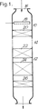
本発明の第1の態様は、添付した図面の関連において説明される。図1は、本発明によるシステムの概要図である。図2はHC存在下(従来技術)、HC不存在下(本発明)での、NOのNO2への転換を比較したグラフである。
【0030】
図1について言及すると、ライトデューティーターボチャージャー直噴ディーゼルエンジン(図中には示していない)が、その場でHCと煤とを含有する排気を領域14でのガスフローと一緒に結合してなる反応器10および12を含んでなるシステムに向けて排出している。領域14は、波線によって表されているが、それは、結合が短くてもよいし、比較的に長くてもよい、例えばエンジン出口で反応器10に結合してもよく、および乗り物本体の下で反応器12に結合してもよい。そのような長い結合はそれ自体で冷却してもよいし、またはひれ領域を包含してもよい。反応器10は必要に応じてそれの入り口16において分散スプレーインジェクター18を包含してもよい。本質的には、HCとCOとの酸化のための初期触媒の床20を包含してもよく、床20に入るガスのHC成分はエンジンから排出されたHCであり、可能であれば18で注入されるHCで増大されてもよい。コントロール手段(図中に示していない)は18でエンジン入り口とHC注入を調整しているガス放出床20の温度に応答して、十分急速なHC酸化を非常に満足しうる床20の温度に保つ。
【0031】
反応器12はその入り口にNOをNO2に酸化するための初期触媒の床22を含有する。床22から放出されるガスは、NO2に富んでおり、それは煤フィルター24を通過し、そこでは煤が捕集され、NO2とO2との反応により酸化される。床22および24は「CRT」システムを構成している。ガス、現在実質的に煤無しは、大気品質基準に適合するのであるならば大気中に放出してもよい。必要に応じて、システムは同じ反応器または可能であれば別のもの、床26、NOx吸収剤とにチャージされた、可能であるなら24と26との間に還元剤またはアンモニアを、可能であるならNOxをN2に還元するための触媒とを包含してもよい。
【0032】
システムの互いの床は、セラミックハニカムの形態であり、活性金属を担持したアルミナウォッシュコートと有するものである。
【実施例】
例1
下記の組成物(v/v)を用いた合成排気ガス
CO2 4.5%
H2O 4.5%
O2 12.0%
CO 200ppm
NO 400ppm
C3H6 0または400ppmまたは800ppm
N2 残部
【0033】
これを、試験反応器に粒子形態でガンマーアルミナ触媒上に1%w/wの白金に、温度150℃と500℃との間で通過させた。この反応器はハニカム上のアルミナウォッシュコートの白金を含有する排気触媒を意味するものとして知られている。出口ガスの組成物は図2に示した通りである。
【0034】
400ppmまたは800ppmHC(プロピレン)含有ガスのガスプロットは、200℃未満では非常に転換率が低いことを示している。しかしながら、炭化水素不存在(床20を除去して)では、150℃で転換率が20%であり、200℃では転換率が85%となっている。このことは、一度HC(C3H6)が第1の酸化工程で除去され、NOをNO2への酸化が非常に完全に行われ、連続工程でのCRTで微粒子の燃焼に対して過剰のNO2を与えることを証明している。現在のライトデューティーディーゼルエンジン設計に適合した冷たい排気ガス温度に関しては、実施的に200℃未満の温度であっても実質的に転換は解消されており、その結果、ガス状のHCは除去されるので、特に有用である。
【0035】
例2
EGR付き、4シリンダーターボーチュージャー直噴ディーゼルエンジン2.5リットル許容および約30の空燃比(重量)で操作した排気ガスを図1の図面に表したシステムの二つの触媒段階に供給した。入り口排気ガス組成(v/v)は下記の通りであった。
【0036】
CO2 5.0%
H2O 4.9%
O2 13.0%
CO 800ppm
NO 100ppm
N2 残部
【0037】
触媒20と触媒22は400cpsiコージェライトハニカム上にアルミナ含有ウォッシュコートに支持した白金属金属を含んでなるものであった。触媒20はターボチャージャーの後のエンジン排気マンニフォールドの外側にちょうど配置し、触媒22はアンダーフロアーの下流部1.0mであった。走行させるに当たり、散布18を用いてディーゼル燃料の注入を調整し、低いがしかしリーンまでの空燃比を与えた。比較走行を20で、触媒成分を除く他の同様のウォッシュコートハニカムを用いて行った。走行は負荷レベルで行われ、22入り口の測定で、225℃〜325℃の範囲で温度を付与した。排出ガスをそれぞれ別個に測定したNO、および全NOx、およびNO2を分析した。下記の表は表示した温度でのNOおよびNO2の濃度を表したものである。
【0038】

添加燃料の存在において非常に低い温度を除いては、第1の工程触媒は実質的に非常に高い濃度のNO2を付与するので、フィルター22上において捕集した煤を非常に効率よく燃焼することを証明している。
【0040】
本発明による第2の態様は下記の例によって示される。粒状形態での様々な酸化触媒支持体を、初期の湿潤技術によって、Pt塩の水溶液を用いて、表1に表したPtwt%で含浸させた。粉末試料を90℃で乾燥させた。すべての試料を空気中で500℃、3時間で焼結した。
【0041】
試料を市販のディーゼルエンジン潤滑油を試料の10wt%で含浸し、そして物理的に混合してその油を吸収させた。熱重量分析および示差熱分析を約40mgの試料に対して、空気雰囲気で用いるSTA1500器械を使用して、斜温10℃/分で実行した。燃焼初期の温度を測定して、そしてDTAピーク下での面積(基本時間を表示して、かつ、試料重量の標準化した)を油燃焼対油蒸発の相対的な測定値として与えた。試料の潤滑油のTGA/DTAプロットは、240℃と400℃との間で生じた蒸発と、400℃で生じた燃焼とを示したものであった。セリアとY−アルミナの結果は下記の表1に示した通りであった。
【0042】
Y−アルミナの両試料は、比較的高いDTA初期温度を有するが、しかしセリアの全ての試料はディーゼル排気ガスに一般的に適合した温度範囲で、非常に十分な還元性を示している。全てのセリア系試料は低温度で炭化水素油の十分な燃焼を示している。
【0044】
追加試験を実質的に同様の方法で、しかしY−アルミナで触媒化したセリアおよび白金の混合物に、油の10wt%で含浸させたセリアおよびアルミナの一または両方を用いた。その結果は下記の表2に示した通りであった。
【0045】
セリアの存在の利便的な効果は全ての試料において見ることができる。
【図面の簡単な説明】
【図1】 図1は、本発明によるシステムの概要図である。
【図2】 図2は、HC存在下(従来技術)、HC不存在下(本発明)での、NOのNO2への転換を比較したグラフである。[0001]
The present invention relates to emission control, and more particularly to improvements in emission control of internal combustion engines such as diesel engines and other lean burn engines.
[0002]
The lean burn engine has a problem that it is difficult to reduce NOx emission in the presence of oxygen. Some types of compression ignition ("diesel") and gasoline engines emit flammable particulates ("soot"). Devices such as engine design, fuel supply, and exhaust gas recirculation can reduce NOx levels outside the engine, but are defined below current limits, eg, in European IV stage regulation Thus, it is difficult to reduce both NOx and soot below the expected limit.
[0003]
This difficulty results in engine designs such as light duty turbocharged direct injection diesel engines, especially those applied to EGR, or generally light duty, when the exhaust gas temperature is very low It seems to be.
[0004]
However, there are a great many naturally aspirated diesel engines used around the world as vehicles (vehicles), marine vessels, and fixed power sources. Although many current engine designs use turbochargers, there are a huge number of naturally aspirated engines, and this will be a problem in the near future. Also, particularly in some countries, including Japan, turbocharger performance improvements are not recognized as challenging, and in some markets, turbochargers are designed or redesigned. It is mentioned that between trucks or buses are excluded from recent engines. All diesel engines produce soot, but the soot from a naturally aspirated engine is a “wet” soot, which retains a deliberate proportion of hydrocarbons adsorbed in the particles. Currently, there are health concerns about the hydrocarbon species absorbed on the ridge. Another aspect of the present invention has particular application in naturally aspirated diesel (compression ignition) engines, but applications can also be found in other engine designs that generate such particulates.
[0005]
As one particularly effective treatment of diesel exhaust, a “continuous regeneration trap” (“CRT”) is commercially available from Johnson Matthey PLC. In EP-A-0341832 Patent CRT system as disclosed in JP-oxidation catalyst to convert NO in the exhaust to NO 2, a gas rich in NO 2 passes through the in the filter, and its NO 2 It easily causes burning with soot, thereby preventing continuous filter regeneration and clogging. CRTs are particularly suitable for so-called heavy duty diesel engines used in buses and heavy trucks, which generally have a relatively high exhaust gas temperature.
[0006]
For example, in the case of turbocharged direct injection engines used for light duty applications such as cars and light trucks, the exhaust gas is relatively low, together with other factors, the CRT system is heavy. The effect is somewhat inferior compared with the case where it is used for a duty engine.
[0007]
The present invention provides a method of treating exhaust gas of an internal combustion engine containing O 2 , NOx, unburned hydrocarbons (“HC”), CO, and soot, the method comprising:
i. A substantial part of HC is oxidized by some oxidation of NO to NO 2 as much as possible,
ii. Treating the product of step i to oxidize NO to NO 2 ;
iii. Collect the spiders,
iv. Combusting the soot collected by reaction with NO 2 and as much as possible the remaining O 2 after step i and step ii.
[0008]
The present invention also provides a system for treating the exhaust gas of such an internal combustion engine, the system comprising:
A first catalyst that receives engine exhaust and that effectively promotes oxidation of HC in situ,
ii. A second catalyst that receives the product of the first catalyst and that effectively promotes the oxidation of NO to NO 2 ;
iii. A filter that effectively collects soot and holds the soot until it burns with the NO 2 and the O 2 remaining after the first catalyst.
[0009]
Since the gas contains soot, the first catalyst and the second catalyst are preferably supported on a structure that allows the passage of fine solid particles. This structure is preferably one that can pass through a passage, for example, a honeycomb having at least 50, if possible, generally preferably 100-900 cells / in 2 ( in terms of SI units “15.5 ˜139.5 cells cm −2 ” , more preferably 100 to 400 cells / in 2 ( “ 15.5 to 62.0 cells cm −2 ” when converted to SI units ).
[0010]
The honeycomb may be structurally composed of ceramic or metal. Such a ceramic may be, for example, alumina, silica, zirconia, or a mixture such as, for example, cordierite or silicon carbide. Such a metal may be a recycled steel such as Fecralloy. Such metals can be applied in many passages per square inch, for example up to 1200. Alternatively, a monolithic support is possible, which tends to include approximately the other of the electrostatic flowable mixture, as routine tests are required or followed.
[0011]
The support structure carries a high surface area support metal coating ("washcoat") as a catalytically active component. In the first catalyst, the coating and these components are selected so that it is effective to remove substantially all of the HC. (It would normally be possible to oxidize CO to CO 2 and to the extent that NO is oxidized to NO 2 ). We are convinced that removing gaseous HC prior to oxidizing NO to NO 2 will eliminate such factors that inhibit the oxidation of NO, but we do not It is not intended that the description be construed as limiting the invention. Although some of the NO can be converted to NO 2 on the first catalyst, unconverted NO may be more effectively converted on the second catalyst. According to the second aspect of the present invention, the HC absorbed on the “wet” soot is combusted on the first catalyst.
[0012]
Effect of the first catalyst is at a level where the rate for converting NO to NO 2 can be sufficiently imparted excess NO 2, is to increase the temperature at the inlet of the second catalyst, also continuous soot combustion reaction also , That's early. As a result, of course, the temperature is NO 2 formation has been a which should not be the range of the equilibrium limit.
[0013]
In the first aspect of the present invention, it is preferable to obtain a sufficient reaction rate on the first catalyst for the reaction of gaseous HC. The inlet temperature can be maximized by placing the catalyst preferably as close as possible to the engine outlet. Therefore, it is typically arranged on the exhaust gas manifold in the cylinder block region, for example before and after the darbocharger if necessary. To obtain or increase such an increase in temperature, additional fuel, such as diesel fuel, may be added upstream of the first catalyst and oxidized in situ. Alternatively or additionally, the engine inlet fuel injection profile may be adjusted to increase HC, or very favorable CO, unburned exhaust gas components. Preferably, measuring the increase in gas temperature is continued to provide a lean gas composition. The reinforcement of HC and / or CO may be continuous, preferably intermittent, and may be determined based on detection of appropriate exhaust gas conditions. However, to achieve, the outlet temperature in the first catalyst stage is preferably at least 200 ° C., and for example up to 500 ° C.
[0014]
Preferably, the first catalyst has a very low ignition temperature as the oxidation of HC and CO. This can be an additional effect when the exhaust gas temperature is typically low, eg, in an idling state, during part of the engine operating cycle.
[0015]
According to the second embodiment, the first catalyst contains a component capable of oxidizing certain hydrocarbons absorbed on wet soot. Suitable forms of ceria are specifically indicated, and such catalysts include other components, preferably similar to one or more white metal catalysts dispersed on an oxide support. It is preferably supported on a monolith catalyst support.
[0016]
A particularly preferred first catalyst of the second aspect comprises ceria or platinum dispersed on a metal oxide washcoat containing ceria. The amount of platinum supported may be up to 200 g / cuft ( “7.06 g / l” in terms of SI units ). Other catalysts or promoter components may also be present. Ceria may be present as a washcoat on platinum catalyzed alumina or other catalyst.
[0017]
The second catalyst may have the same composition as the first catalyst, but is preferably designed to make the reaction of NO to NO2, temperature and space velocity very effective. For example, the two catalysts may be different. Therefore, the conditions for HC oxidation and NO oxidation may be optimized independently. The temperature in the second catalyst step is preferably 150 to 350 ° C. (Since NO oxidation is not exothermic at all, there is little difference between the inlet and outlet temperatures).
[0018]
In the catalyst, the active metal generally comprises a white metal metal (“PGM”), in particular platinum and / or palladium, and optionally other PGMs such as rhodium. The exact composition of the catalyst is selected to meet local requirements. Preferably, they have a relatively high platinum loading (for example, 10-150 g / ft 3 (in terms of SI units, “0.35 to 5.3 g / l”) ), and if necessary, For example, it may have a catalyst component or catalyst promoter component such as rhodium or palladium.
[0019]
The filter may be any capable of collecting soot without causing excessive back pressure. Its detailed specifications should be selected according to the engine characteristics and the regulations to be adapted. It can be any ceramic form filter, ceramic fiber filter, sintered metal or wire filter. It provides for removal of 50-100%, preferably at least 60%, more preferably 85%, or more of soot measured in the exhaust gas. There may be a safety device bypass or a two-stage filter to satisfy conditions that may otherwise be rendered meaningless or obstructed under certain engine operating conditions. If desired, the filter may be catalyzed or partially catalyzed to support combustion. Various catalysts are known as suitable, and these comprise one or more of vanadium, cerium, and La / Cs / V oxide mixtures and are supported by PGM. If required, the present invention generates or has generated a possibility of initial combustion of the soot, e.g. the engine operating conditions are contemplating, but the gas temperature has not reached a sufficient combustion temperature, e.g. at the beginning of operation. Including applying electrical heating to a portion of the filter. Soot is usually carbon and / or heavy hydrocarbons and is converted to carbon oxide and water vapor.
[0020]
It is preferred to use low sulfur containing diesel fuel, preferably less than 50 ppm, more preferably "USLD" or ultra-low sulfur diesel fuel that is 10 ppm or less.
[0021]
The present invention also provides an engine in combination with the system and engine operating methods defined herein.
[0022]
In this combination, in the first embodiment, the first catalyst may be located near the exhaust gas source where it is possible to manipulate the maximum convenient temperature and reaction rate. The exit gas from this catalyst may be cooled before entering the second catalyst, for example with non-isolated or fragmented pipes.
[0023]
In the second aspect combination, the first catalyst is preferably located close to the housing or “can”, similar to the second catalyst and filter. A single catalyst monolith or “brick”, one end carrying the first catalyst, and the other end carrying the second catalyst, providing appropriate catalyst design and catalyst manufacturing techniques, and gas flow rates and It is possible to contemplate that the space velocity is suitable.
[0024]
This combination may include techniques such as EGR.
[0025]
This combination may include any one of the following sensors: fuel composition, air-fuel ratio at the engine inlet, exhaust gas composition at the critical stage, and pressure loss. If engine inlet conditioning and / or fuel injection is used, then a temperature sensor is preferably provided after the first catalyst and possibly before the catalyst and / or at the inlet of the NO oxidation catalyst. The control system also includes means for displaying engine operating information, computer means for effectively evaluating the data from the sensors, and the engine to the desired operating conditions taking into account, for example, star time, variable load, and fluctuating opportunities. A control restraint coupling that effectively regulates and, if desired, injecting fuel into the exhaust gas may also be included.
[0026]
Preferably, the engine is a diesel engine, but other engines including direct injection gasoline engines are also effective in the present invention. The engine may be a vehicle power source, or may be a fixed power source or a reserve power source. The most useful as the first aspect is used in light duty engines, particularly passenger cars or light trucks or vans, as previously disclosed herein. In general, “light” means less than 3500 kg riding weight. This typically corresponds to cylinder tolerances up to 6.0 liters and outputs up to 300 kW. The present invention has valuable performance as another duty engine. Preferably, the second aspect applies to a “heavy duty” engine.
[0027]
What is described below is credible, but we hope that the scope of the invention is not limited by this theory. The preferred embodiment system and method of the present invention is capable of combusting hydrocarbons in the first zone, generating sufficient NO2 in the second zone, and under typical diesel engine operating conditions, It gives the correct equilibrium between NO 2 and carbon for burning in the particulate trap.
[0028]
If desired, the present invention may be combined with additional means to reduce NOx in the gas remaining in the system of the present invention, including a system that includes a three-way catalyst type catalyst or reducing agent addition. And one or both of the NOx reduction catalyst and the recyclable absorbent. Such means are generally known.
[0029]
The first aspect of the invention will be described in connection with the accompanying drawings. FIG. 1 is a schematic diagram of a system according to the present invention. FIG. 2 is a graph comparing the conversion of NO to NO 2 in the presence of HC (prior art) and in the absence of HC (invention).
[0030]
Referring to FIG. 1, a light-duty turbocharged direct injection diesel engine (not shown in the figure) combines the exhaust containing HC and soot together with the gas flow in
[0031]
The
[0032]
The mutual floors of the system are in the form of a ceramic honeycomb and have an alumina washcoat carrying an active metal.
【Example】
Example 1
Synthetic exhaust gas CO 2 4.5% using the following composition (v / v)
H 2 O 4.5%
O 2 12.0%
CO 200ppm
NO 400ppm
C 3 H 6 0 or 400 ppm or 800 ppm
N 2 balance 【0033】
This was passed through a test reactor in the form of particles through 1% w / w platinum over a gamma alumina catalyst at a temperature between 150 ° C and 500 ° C. This reactor is known to mean an exhaust catalyst containing platinum in an alumina washcoat on a honeycomb. The composition of the outlet gas is as shown in FIG.
[0034]
The gas plot for 400 ppm or 800 ppm HC (propylene) containing gas shows very low conversion below 200 ° C. However, in the absence of hydrocarbons (with the
[0035]
Example 2
Exhaust gas operated with a 4-cylinder turbocharger direct injection diesel engine with EGR of 2.5 liters allowed and an air / fuel ratio (weight) of about 30 was fed to the two catalyst stages of the system depicted in the drawing of FIG. The inlet exhaust gas composition (v / v) was as follows.
[0036]
CO 2 5.0%
H 2 O 4.9%
O 2 13.0%
CO 800ppm
NO 100ppm
N 2 remainder [0037]
[0038]
Except for very low temperatures in the presence of added fuel, the first stage catalyst imparts a substantially very high concentration of NO 2 so that the soot collected on the
[0040]
A second embodiment according to the present invention is illustrated by the following example. Various oxidation catalyst supports in granular form were impregnated with Ptwt% as shown in Table 1 using an aqueous solution of Pt salt by an initial wetting technique. The powder sample was dried at 90 ° C. All samples were sintered in air at 500 ° C. for 3 hours.
[0041]
The sample was impregnated with a commercial diesel engine lubricating oil at 10 wt% of the sample and physically mixed to absorb the oil. Thermogravimetric analysis and differential thermal analysis were performed on an approximately 40 mg sample using a STA 1500 instrument used in an air atmosphere at an oblique temperature of 10 ° C./min. The temperature at the beginning of combustion was measured and the area under the DTA peak (basic time displayed and sample weight standardized) was given as a relative measure of oil combustion versus oil evaporation. A TGA / DTA plot of the sample lubricant showed evaporation that occurred between 240 ° C. and 400 ° C. and combustion that occurred at 400 ° C. The results for ceria and Y-alumina were as shown in Table 1 below.
[0042]
Both samples of Y-alumina have a relatively high initial DTA temperature, but all samples of ceria show very good reducibility in a temperature range generally compatible with diesel exhaust. All ceria samples show sufficient combustion of hydrocarbon oils at low temperatures.
[0044]
Additional testing was performed in a substantially similar manner, but with one or both of ceria and alumina impregnated with 10 wt% of oil in a mixture of ceria and platinum catalyzed with Y-alumina. The results were as shown in Table 2 below.
[0045]
The convenient effect of the presence of ceria can be seen in all samples.
[Brief description of the drawings]
FIG. 1 is a schematic diagram of a system according to the present invention.
FIG. 2 is a graph comparing the conversion of NO to NO 2 in the presence of HC (prior art) and in the absence of HC (invention).
Claims (17)
(i)排気ガス中の炭化水素(HC)を酸化する第1触媒と、
(ii)第1触媒から離れた排気ガス中のNOをNO2に酸化する第2触媒と、及び
(iii)煤を捕集し、かつ、前記NO2と、条件に応じて、第1触媒の後に残余したO2との反応により燃焼するまで前記煤を保持してなる、フィルタとを備えてなる、排気システム。An exhaust system for an internal combustion engine,
(I) a first catalyst that oxidizes hydrocarbons (HC) in the exhaust gas;
(Ii) a second catalyst that oxidizes NO in the exhaust gas away from the first catalyst to NO 2 , and (iii) traps soot, and the first catalyst depending on the NO 2 and conditions An exhaust system comprising a filter that holds the soot until it burns due to a reaction with O 2 remaining after.
第1触媒が7.06g/lまでの白金を含んでなる、請求項6に記載の排気システム。In the case dependent on claim 2,
The exhaust system of claim 6, wherein the first catalyst comprises up to 7.06 g / l platinum.
第1触媒が第2触媒に近接した場所に位置する、請求項8又は9に記載の排気システム。In the case dependent on claim 6,
The exhaust system according to claim 8 or 9, wherein the first catalyst is located in the vicinity of the second catalyst.
前記NOxを減少させる手段が、前記フィルタの下流部に位置する、請求項1〜12のいずれか一項に記載の方法。Further comprising means for reducing NOx in the exhaust gas,
The method according to any one of claims 1 to 12, wherein the means for reducing NOx is located downstream of the filter.
(a)HCの実質的な一部を、可能な限りNOをNO2とする幾つかの酸化により酸化し、
(b)工程(a)における生産物を処理し、NOをNO2に酸化し、
(c)前記煤を捕集し、
(d)NO2および可能な限り工程(a)及び工程(b)との後に残余したO2との反応により、捕集した前記煤を燃焼することを含んでなる、方法。And O 2, and NOx, to a method of treatment and unburnt hydrocarbons HC, and CO, and the exhaust gas of an internal combustion engine containing a soot,
(A) a substantial part of HC is oxidized by several oxidations where NO is NO 2 as much as possible,
(B) processing the product in step (a), the oxidation of NO to NO 2,
(C) collecting the spider;
(D) A method comprising combusting the soot collected by reaction with NO 2 and possibly remaining O 2 after steps (a) and (b).
Applications Claiming Priority (5)
| Application Number | Priority Date | Filing Date | Title |
|---|---|---|---|
| GBGB9826748.7A GB9826748D0 (en) | 1998-12-05 | 1998-12-05 | Improvements in particulate control |
| GB9826748.7 | 1999-06-09 | ||
| GBGB9913300.1A GB9913300D0 (en) | 1999-06-09 | 1999-06-09 | Improvements in emissions control |
| GB9913300.1 | 1999-06-09 | ||
| PCT/GB1999/003971 WO2000034632A1 (en) | 1998-12-05 | 1999-11-29 | Improvements in particulate control |
Publications (3)
| Publication Number | Publication Date |
|---|---|
| JP2002531762A JP2002531762A (en) | 2002-09-24 |
| JP2002531762A5 JP2002531762A5 (en) | 2007-01-25 |
| JP4381610B2 true JP4381610B2 (en) | 2009-12-09 |
Family
ID=26314790
Family Applications (1)
| Application Number | Title | Priority Date | Filing Date |
|---|---|---|---|
| JP2000587056A Expired - Fee Related JP4381610B2 (en) | 1998-12-05 | 1999-11-29 | Improvements in particulate control |
Country Status (10)
| Country | Link |
|---|---|
| US (1) | US6877313B1 (en) |
| EP (1) | EP1135581B1 (en) |
| JP (1) | JP4381610B2 (en) |
| KR (1) | KR100623486B1 (en) |
| AT (1) | ATE224507T1 (en) |
| AU (1) | AU1288800A (en) |
| DE (1) | DE69903066T2 (en) |
| DK (1) | DK1135581T3 (en) |
| TW (1) | TW457334B (en) |
| WO (1) | WO2000034632A1 (en) |
Families Citing this family (57)
| Publication number | Priority date | Publication date | Assignee | Title |
|---|---|---|---|---|
| GB9913331D0 (en) | 1999-06-09 | 1999-08-11 | Johnson Matthey Plc | Treatment of exhaust gas |
| DE19955324A1 (en) * | 1999-11-17 | 2001-05-23 | Volkswagen Ag | Device and method for reducing harmful components in the exhaust gas of an internal combustion engine, in particular a diesel internal combustion engine |
| DE10036401B4 (en) * | 2000-07-26 | 2009-07-30 | Volkswagen Ag | Device for reducing the harmful components in the exhaust gas of an internal combustion engine, in particular a diesel internal combustion engine |
| DE10118327A1 (en) | 2001-04-12 | 2002-10-17 | Emitec Emissionstechnologie | Diesel exhaust purification system for automobiles, comprises oxidative catalysts converting carbon monoxide, hydrocarbon and nitrogen oxides, followed by particle trap |
| JP2002336627A (en) * | 2001-05-15 | 2002-11-26 | Mitsui & Co Ltd | Apparatus for decreasing carbon particles |
| DE10128414A1 (en) * | 2001-06-12 | 2002-12-19 | Daimler Chrysler Ag | Exhaust gas system for cleaning internal combustion engine exhaust gases comprises a reducing agent supply having a hydrogen-producing unit for enriching the exhaust gas with hydrogen |
| WO2003002854A1 (en) * | 2001-06-26 | 2003-01-09 | N.V. Bekaert S.A. | A method of desulfation of nox-adsorbers |
| EP1270886A1 (en) * | 2001-06-26 | 2003-01-02 | N.V. Bekaert S.A. | Process and device for decreasing the amount of NOx in a diesel exhaust system |
| FR2829180B1 (en) * | 2001-08-28 | 2005-10-28 | Ct De Rech S En Machines Therm | METHOD FOR REGENERATING AN EXHAUST GAS FILTRATION DEVICE FOR A DIESEL ENGINE AND DEVICE FOR IMPLEMENTING THE SAME |
| AUPR812401A0 (en) * | 2001-10-08 | 2001-11-01 | Orbital Engine Company (Australia) Proprietary Limited | An internal combustion engine |
| JP4157304B2 (en) | 2002-02-05 | 2008-10-01 | 日本碍子株式会社 | Honeycomb structure |
| FR2836513B1 (en) | 2002-02-25 | 2005-12-02 | Renault Vehicules Ind | EXHAUST LINE AND MOTOR VEHICLE THUS EQUIPPED |
| DE10223736A1 (en) * | 2002-05-28 | 2003-12-11 | Man Nutzfahrzeuge Ag | Device for reducing soot particles contained in the exhaust gas of a vehicle diesel engine |
| GB0218540D0 (en) * | 2002-08-09 | 2002-09-18 | Johnson Matthey Plc | Engine exhaust treatment |
| GB0220645D0 (en) * | 2002-09-05 | 2002-10-16 | Johnson Matthey Plc | Exhaust system for a lean burn ic engine |
| DE10254764A1 (en) * | 2002-11-22 | 2004-06-03 | Emitec Gesellschaft Für Emissionstechnologie Mbh | exhaust system |
| WO2004071646A2 (en) * | 2003-02-12 | 2004-08-26 | Delphi Technologies, Inc. | SYSTEM AND METHOD OF NOx ABATEMENT |
| GB0304939D0 (en) * | 2003-03-05 | 2003-04-09 | Johnson Matthey Plc | Light-duty diesel engine and a particulate filter therefor |
| GB0305415D0 (en) | 2003-03-08 | 2003-04-16 | Johnson Matthey Plc | Exhaust system for lean burn IC engine including particulate filter and NOx absorbent |
| DE10321105A1 (en) * | 2003-05-09 | 2004-12-02 | Emitec Gesellschaft Für Emissionstechnologie Mbh | Regeneration of a particle trap |
| DE10349876A1 (en) * | 2003-10-25 | 2005-05-25 | Daimlerchrysler Ag | Process to operate the catalytic components of an automotive exhaust system in three oxidizing and reducing modes |
| EP1637706A1 (en) * | 2004-09-16 | 2006-03-22 | Delphi Technologies, Inc. | System and method for increasing the temperature of gases within an exhaust of an internal combustion engine |
| FR2876413B1 (en) | 2004-10-07 | 2007-03-16 | Renault Sas | PARTICULATE FILTER IMPREGNATED FROM A CATALYTIC FORMULATION FOR INTERNAL COMBUSTION ENGINE |
| US7146802B2 (en) * | 2004-10-07 | 2006-12-12 | General Motors Corporation | Reducing NOx emissions with a staged catalyst |
| GB2406803A (en) | 2004-11-23 | 2005-04-13 | Johnson Matthey Plc | Exhaust system comprising exotherm-generating catalyst |
| US8115373B2 (en) | 2005-07-06 | 2012-02-14 | Rochester Institute Of Technology | Self-regenerating particulate trap systems for emissions and methods thereof |
| EP1947303A4 (en) | 2005-10-18 | 2010-11-10 | Toyota Motor Co Ltd | Exhaust cleaner for internal combustion engine |
| DE102005049655A1 (en) * | 2005-10-18 | 2007-04-19 | Man Nutzfahrzeuge Ag | Preventing unwanted nitrogen dioxide emission from combustion engines involves adapting engine operating point and catalyzer state so only nitrogen dioxide required for exhaust gas treatment is present in exhaust gas downstream of catalyzer |
| JP4839773B2 (en) * | 2005-10-21 | 2011-12-21 | トヨタ自動車株式会社 | Method for manufacturing PM purification device |
| JP5296291B2 (en) * | 2005-12-08 | 2013-09-25 | いすゞ自動車株式会社 | Exhaust gas purification system |
| JP4523911B2 (en) * | 2005-12-14 | 2010-08-11 | 本田技研工業株式会社 | Exhaust gas purification device |
| US7343736B2 (en) | 2006-02-27 | 2008-03-18 | Detroit Diesel Corporation | Flexible exhaust emission aftertreatment system for compression cycle diesel engines |
| US7862640B2 (en) * | 2006-03-21 | 2011-01-04 | Donaldson Company, Inc. | Low temperature diesel particulate matter reduction system |
| DE502006002815D1 (en) * | 2006-03-23 | 2009-03-26 | Ford Global Tech Llc | Method for operating an internal combustion engine with exhaust aftertreatment |
| JP4715581B2 (en) * | 2006-03-24 | 2011-07-06 | いすゞ自動車株式会社 | Exhaust gas purification system control method and exhaust gas purification system |
| JP4582806B2 (en) | 2006-06-09 | 2010-11-17 | 株式会社豊田中央研究所 | Exhaust gas purification device |
| JP4449947B2 (en) | 2006-07-05 | 2010-04-14 | トヨタ自動車株式会社 | Control device for internal combustion engine |
| US20080053070A1 (en) * | 2006-09-01 | 2008-03-06 | Andrew Hatton | Apparatus and method for regenerating a particulate filter with a non-uniformly loaded oxidation catalyst |
| US7937936B2 (en) * | 2007-01-16 | 2011-05-10 | Deere & Company | Vehicle exhaust component arrangement |
| DE102007008954B4 (en) | 2007-02-21 | 2009-12-17 | Umicore Ag & Co. Kg | Catalyst system and its use |
| FR2913431B1 (en) * | 2007-03-06 | 2009-04-24 | Rhodia Recherches & Tech | METHOD FOR OPERATING A DIESEL ENGINE TO FACILITATE THE REGENERATION OF A PARTICLE FILTER ON THE EXHAUST LINE |
| JP4274270B2 (en) * | 2007-06-26 | 2009-06-03 | いすゞ自動車株式会社 | NOx purification system and control method of NOx purification system |
| JP4849035B2 (en) * | 2007-08-08 | 2011-12-28 | マツダ株式会社 | Particulate filter with catalyst |
| US9863297B2 (en) * | 2007-12-12 | 2018-01-09 | Basf Corporation | Emission treatment system |
| US9993771B2 (en) | 2007-12-12 | 2018-06-12 | Basf Corporation | Emission treatment catalysts, systems and methods |
| DE102008026178A1 (en) * | 2008-05-30 | 2009-12-03 | Deutz Ag | High efficiency SCR catalyst |
| JP4507018B2 (en) * | 2008-06-27 | 2010-07-21 | 三菱自動車工業株式会社 | Exhaust gas purification device for internal combustion engine |
| US8220252B2 (en) * | 2009-05-05 | 2012-07-17 | Caterpillar CleanAIR Systems Inc. | Exhaust gas emissions reactor and method of treating exhaust gas |
| JP2011012563A (en) * | 2009-06-30 | 2011-01-20 | Toyota Industries Corp | Exhaust gas purification system |
| US8304366B2 (en) * | 2010-11-24 | 2012-11-06 | Ford Global Technologies, Llc | System for remediating emissions and method of use |
| US8769932B2 (en) * | 2011-10-13 | 2014-07-08 | GM Global Technology Operations LLC | Cold start NO2 generation system |
| US8997461B2 (en) | 2012-05-21 | 2015-04-07 | Cummins Emission Solutions Inc. | Aftertreatment system having two SCR catalysts |
| GB201220912D0 (en) | 2012-11-21 | 2013-01-02 | Johnson Matthey Plc | Oxidation catalyst for treating the exhaust gas of a compression ignition engine |
| DE102015000955A1 (en) | 2014-01-20 | 2015-07-23 | Cummins Inc. | Systems and methods for reducing NOx and HC emissions |
| US9512761B2 (en) | 2014-02-28 | 2016-12-06 | Cummins Inc. | Systems and methods for NOx reduction and aftertreatment control using passive NOx adsorption |
| US9567888B2 (en) | 2014-03-27 | 2017-02-14 | Cummins Inc. | Systems and methods to reduce reductant consumption in exhaust aftertreament systems |
| US9903307B2 (en) | 2016-01-04 | 2018-02-27 | Ford Global Technologies, Llc | Method of fuel injection control |
Family Cites Families (13)
| Publication number | Priority date | Publication date | Assignee | Title |
|---|---|---|---|---|
| DE3337903A1 (en) | 1983-10-19 | 1985-05-09 | Werner 7101 Flein Baum | Catalyst arrangement |
| DE3608635A1 (en) | 1986-03-14 | 1987-09-17 | Drache Keramikfilter | EXHAUST GAS REACTOR AND METHOD FOR THE PRODUCTION THEREOF |
| US4902487A (en) * | 1988-05-13 | 1990-02-20 | Johnson Matthey, Inc. | Treatment of diesel exhaust gases |
| KR960004832B1 (en) * | 1992-08-24 | 1996-04-16 | 미쯔비시지도오샤고오교오 가부시기가이샤 | Engine exhaust gas purification apparatus |
| JP3344040B2 (en) * | 1993-11-25 | 2002-11-11 | トヨタ自動車株式会社 | Exhaust gas purification device for internal combustion engine |
| DE4406648C1 (en) * | 1994-03-01 | 1995-08-10 | Daimler Benz Ag | Catalytic reduction of hydrocarbons, carbon monoxide and nitrogen oxides from i.c engine exhaust |
| JP3375790B2 (en) * | 1995-06-23 | 2003-02-10 | 日本碍子株式会社 | Exhaust gas purification system and exhaust gas purification method |
| JP3899534B2 (en) * | 1995-08-14 | 2007-03-28 | トヨタ自動車株式会社 | Exhaust gas purification method for diesel engine |
| US6038854A (en) * | 1996-08-19 | 2000-03-21 | The Regents Of The University Of California | Plasma regenerated particulate trap and NOx reduction system |
| US5891409A (en) * | 1996-08-19 | 1999-04-06 | The Regents Of The University Of California | Pre-converted nitric oxide gas in catalytic reduction system |
| GB9621215D0 (en) | 1996-10-11 | 1996-11-27 | Johnson Matthey Plc | Emission control |
| US6293096B1 (en) * | 1999-06-23 | 2001-09-25 | Southwest Research Institute | Multiple stage aftertreatment system |
| JP2002188432A (en) * | 2000-12-19 | 2002-07-05 | Isuzu Motors Ltd | Exhaust gas purifying device for diesel engine |
-
1999
- 1999-11-29 DE DE69903066T patent/DE69903066T2/en not_active Expired - Lifetime
- 1999-11-29 DK DK99956246T patent/DK1135581T3/en active
- 1999-11-29 US US09/857,386 patent/US6877313B1/en not_active Expired - Lifetime
- 1999-11-29 KR KR1020017006995A patent/KR100623486B1/en not_active IP Right Cessation
- 1999-11-29 JP JP2000587056A patent/JP4381610B2/en not_active Expired - Fee Related
- 1999-11-29 AT AT99956246T patent/ATE224507T1/en not_active IP Right Cessation
- 1999-11-29 EP EP99956246A patent/EP1135581B1/en not_active Expired - Lifetime
- 1999-11-29 AU AU12888/00A patent/AU1288800A/en not_active Abandoned
- 1999-11-29 WO PCT/GB1999/003971 patent/WO2000034632A1/en active IP Right Grant
- 1999-12-02 TW TW088121087A patent/TW457334B/en active
Also Published As
| Publication number | Publication date |
|---|---|
| EP1135581A1 (en) | 2001-09-26 |
| TW457334B (en) | 2001-10-01 |
| ATE224507T1 (en) | 2002-10-15 |
| EP1135581B1 (en) | 2002-09-18 |
| KR20010080690A (en) | 2001-08-22 |
| KR100623486B1 (en) | 2006-09-12 |
| WO2000034632A1 (en) | 2000-06-15 |
| DE69903066D1 (en) | 2002-10-24 |
| AU1288800A (en) | 2000-06-26 |
| JP2002531762A (en) | 2002-09-24 |
| DE69903066T2 (en) | 2003-03-13 |
| US6877313B1 (en) | 2005-04-12 |
| DK1135581T3 (en) | 2003-01-27 |
Similar Documents
| Publication | Publication Date | Title |
|---|---|---|
| JP4381610B2 (en) | Improvements in particulate control | |
| KR101978617B1 (en) | Exhaust system comprising a nox storage catalyst and catalysed soot filter | |
| US11732631B2 (en) | Exhaust gas purification system for a gasoline engine | |
| JPH10159552A (en) | Exhaust gas emission control device | |
| JP2002502927A (en) | NOx reduction mechanism in exhaust gas | |
| EP3639922B1 (en) | Exhaust gas purification system for a gasoline engine | |
| JP2015163790A (en) | Method and device for purifying diesel exhaust gas | |
| US11859526B2 (en) | Exhaust gas purification system for a gasoline engine | |
| US11547969B2 (en) | Exhaust gas purification system for a gasoline engine | |
| US11377993B2 (en) | Exhaust gas purification system for a gasoline engine | |
| US11649753B2 (en) | Exhaust gas purification system for a gasoline engine | |
| CA2607367C (en) | Method and apparatus for the purification of exhaust gas from a compression ignition engine | |
| JPH10184348A (en) | Nox reduction method for emission for internal combustion engine | |
| US20210332731A1 (en) | Exhaust gas purification system for a gasoline engine | |
| US8236261B2 (en) | Exhaust system having a gold-platinum group metal catalyst | |
| JP2007516379A (en) | System for supporting regeneration of purification means contained in exhaust line of motor vehicle | |
| JP2007501356A (en) | Method for purifying diesel engine exhaust gas with diesel oxidation catalyst | |
| JP2005288362A (en) | Diesel engine exhaust gas purification apparatus | |
| KR20220160734A (en) | Apparatus and method for engine control of commercial vehicle |
Legal Events
| Date | Code | Title | Description |
|---|---|---|---|
| A521 | Request for written amendment filed |
Free format text: JAPANESE INTERMEDIATE CODE: A523 Effective date: 20061129 |
|
| A621 | Written request for application examination |
Free format text: JAPANESE INTERMEDIATE CODE: A621 Effective date: 20061129 |
|
| A131 | Notification of reasons for refusal |
Free format text: JAPANESE INTERMEDIATE CODE: A131 Effective date: 20090421 |
|
| A601 | Written request for extension of time |
Free format text: JAPANESE INTERMEDIATE CODE: A601 Effective date: 20090717 |
|
| A521 | Request for written amendment filed |
Free format text: JAPANESE INTERMEDIATE CODE: A523 Effective date: 20090724 |
|
| A602 | Written permission of extension of time |
Free format text: JAPANESE INTERMEDIATE CODE: A602 Effective date: 20090727 |
|
| TRDD | Decision of grant or rejection written | ||
| A01 | Written decision to grant a patent or to grant a registration (utility model) |
Free format text: JAPANESE INTERMEDIATE CODE: A01 Effective date: 20090821 |
|
| A01 | Written decision to grant a patent or to grant a registration (utility model) |
Free format text: JAPANESE INTERMEDIATE CODE: A01 |
|
| A61 | First payment of annual fees (during grant procedure) |
Free format text: JAPANESE INTERMEDIATE CODE: A61 Effective date: 20090916 |
|
| FPAY | Renewal fee payment (event date is renewal date of database) |
Free format text: PAYMENT UNTIL: 20121002 Year of fee payment: 3 |
|
| R150 | Certificate of patent or registration of utility model |
Free format text: JAPANESE INTERMEDIATE CODE: R150 |
|
| FPAY | Renewal fee payment (event date is renewal date of database) |
Free format text: PAYMENT UNTIL: 20131002 Year of fee payment: 4 |
|
| R250 | Receipt of annual fees |
Free format text: JAPANESE INTERMEDIATE CODE: R250 |
|
| R250 | Receipt of annual fees |
Free format text: JAPANESE INTERMEDIATE CODE: R250 |
|
| R250 | Receipt of annual fees |
Free format text: JAPANESE INTERMEDIATE CODE: R250 |
|
| LAPS | Cancellation because of no payment of annual fees |