JP4380366B2 - Protective member - Google Patents
Protective member Download PDFInfo
- Publication number
- JP4380366B2 JP4380366B2 JP2004059278A JP2004059278A JP4380366B2 JP 4380366 B2 JP4380366 B2 JP 4380366B2 JP 2004059278 A JP2004059278 A JP 2004059278A JP 2004059278 A JP2004059278 A JP 2004059278A JP 4380366 B2 JP4380366 B2 JP 4380366B2
- Authority
- JP
- Japan
- Prior art keywords
- cover
- leg
- attached
- protective member
- protected
- Prior art date
- Legal status (The legal status is an assumption and is not a legal conclusion. Google has not performed a legal analysis and makes no representation as to the accuracy of the status listed.)
- Expired - Fee Related
Links
Images


Landscapes
- Installation Of Indoor Wiring (AREA)
Description
本発明は、保護部材に関する。 The present invention relates to a protective member.
従来から精密機械の内部、特に複写機やプリンターなどの画像成形装置において、内部配線の増加に伴い、フラットケーブルやワイヤーハーネスを配線保持する際には、筐体の一部に取り付け部材をはめ込み部材の間にフラットケーブルを挟んで配線保持をしている例がある(例えば、特許文献1参照)。 Conventionally, when holding flat cables and wire harnesses in the interior of precision machines, especially in image forming devices such as copiers and printers, the mounting member is fitted into a part of the housing. There is an example of holding the wiring with a flat cable between them (see, for example, Patent Document 1).
また、装置内部に可動部分が存在し、且つワイヤーハーネスを可動部分の近傍に配置する必要がある場合、可動部材に連動してワイヤーハーネスの一部に張力を付与または解除する方向に保持部材を移動させる連動手段とを備えるように構成された保持部材(例えば、特許文献2参照)が提案されている。これによりワイヤーハーネスと可動部分が接触あるいは干渉して故障が発生する事態を防止することができる。 In addition, when there is a movable part inside the apparatus and it is necessary to arrange the wire harness in the vicinity of the movable part, the holding member is attached in a direction to apply or release tension to a part of the wire harness in conjunction with the movable member. A holding member (see, for example, Patent Document 2) configured to include interlocking means for movement has been proposed. As a result, it is possible to prevent a failure from occurring due to contact or interference between the wire harness and the movable part.
しかし特許文献1および2の例では例えば一部のDCブラシレスモータのように軸ではなく外部が回転するモータなどの可動部上にはハーネスの配線ができず、取り付け場所に制限が生じる。また特許文献2の例ではハーネス等の場所が移動・変更となった場合、位置変更が難しくコスト高になり、フレキシブルに対応ができない。あるいは取外しに力がかかったり、工具が必要だったり、周辺部品のメンテナンスや部品交換に手間がかかる。
本発明は上記事実を考慮し、簡単に着脱可能で可動部分の近傍にも配線可能な保護部材を提供することを目的とする。 In view of the above facts, an object of the present invention is to provide a protective member that can be easily detached and wired near a movable part.
請求項1に記載の保護部材は、被取付部材に取付けられた可動部材である被保護部材を覆うカバーと、前記カバーの両端部から前記被取付部材に向かって延設され、前記被保護部材を跨いで両側面を囲い、先端部に設けられた固定部材で前記被取付部材の裏表を挟持する脚部と、前記カバーに設けられた配線ホルダと、を有し、前記脚部は前記カバーを間に置いて一方を開閉させると他方が閉開する、板状に形成された脚板であり、前記カバーと前記被保護部材との間に空間を設けた状態で前記脚部が前記被取付部材に係止されることを特徴とする。
The protection member according to claim 1 is a cover that covers a protected member that is a movable member attached to the attached member, and extends from both ends of the cover toward the attached member, and the protected member A leg part that surrounds both sides across the board and sandwiches the back and front of the attached member with a fixing member provided at the tip part, and a wiring holder provided on the cover, wherein the leg part is the cover. When the one is opened and closed with the other in between, the other is closed and opened, and the other is closed, and the leg is attached to the attached portion with a space provided between the cover and the protected member. It is locked to the member.
上記構成の発明では、脚部先端の固定部材が被取付部材の縁部または貫通口を把持するので、取付け・取外し方向の力に対して確実に保護部材を固定でき、脚部の一方を開閉することにより、可動部材である被保護部材とカバーとの間に空間を有する状態のまま、保護部材を被取付部材に係止することができ、かつカバー上で配線部材を固定できるので、配線部材が可動する被保護部材に干渉する危険を更に減らすことができる。また脚部が板状に形成された脚板であるので、モータなどの可動部を大面積で覆うことができハーネス等が絡まる恐れを軽減し、脚部の一方を開閉することにより保護部材を被取付部材に係止することができるので簡単に着脱可能な保護部材とすることができる。
In the invention with the above configuration, since the fixing member at the tip of the leg grips the edge or the through-hole of the attached member, the protection member can be securely fixed against the force in the attaching / detaching direction, and one of the legs is opened and closed. By doing so, the protective member can be locked to the attached member while maintaining a space between the protected member, which is a movable member, and the cover, and the wiring member can be fixed on the cover. The risk of the member interfering with the movable member to be moved can be further reduced. In addition, since the leg portion is a leg plate formed in a plate shape, the movable portion such as a motor can be covered with a large area to reduce the possibility of the harness being entangled, and the protective member is covered by opening and closing one of the leg portions. Since it can be locked to the mounting member, the protective member can be easily attached and detached.
請求項2に記載の保護部材は、前記脚板は前記カバーに揺動自在に支持され弾性部材で開方向または閉方向に付勢されていることを特徴とする。
The protection member according to claim 2 is characterized in that the leg plate is swingably supported by the cover and is urged in an opening direction or a closing direction by an elastic member .
上記構成の発明では、ワンタッチで脚板を開閉可能なので止め具、工具が不要であり、簡単に取付け・取外しができる。
In the invention with the above-described configuration , the leg plate can be opened and closed with one touch, so there is no need for a stopper or a tool, and it can be easily attached and detached .
請求項3に記載の保護部材は、前記脚板は前記カバーと一体形成され弾性変形して開閉することを特徴とする。
The protective member according to claim 3 is characterized in that the leg plate is integrally formed with the cover and is elastically deformed to open and close .
上記構成の発明では、弾性変形する脚板を開閉することで保護部材の取付け・取外しを行うので、部品点数が少なく構造が簡単な保護部材とすることができる。
In the invention having the above-described configuration , the protective member is attached and detached by opening and closing the leg plate that is elastically deformed, so that the protective member can be provided with a simple structure and a small number of parts .
上記構成の発明では、ワンタッチで脚板を開閉可能なので止め具、工具が不要であり、簡単に取付け・取外しができる。 In the invention with the above-described configuration, the leg plate can be opened and closed with one touch, so there is no need for a stopper or a tool, and it can be easily attached and detached.
請求項4に記載の保護部材は、前記脚板は前記カバーと一体形成され弾性変形して開閉することを特徴とする。 The protection member according to claim 4 is characterized in that the leg plate is integrally formed with the cover and is elastically deformed to open and close.
上記構成の発明では、弾性変形する脚板を開閉することで保護部材の取付け・取外しを行うので、部品点数が少なく構造が簡単な保護部材とすることができる。 In the invention having the above-described configuration, the protective member is attached and detached by opening and closing the leg plate that is elastically deformed, so that the protective member can be provided with a simple structure and a small number of parts.
本発明は上記構成としたので、簡単に着脱可能で可動部分の近傍にも配線可能な保護部材とすることができた。 Since the present invention has the above-described configuration, it was possible to provide a protective member that can be easily detached and wired near the movable part.
図1には、本発明の第一実施形態に係る保護部材の構造が示されている。 FIG. 1 shows the structure of the protective member according to the first embodiment of the present invention.
図1のように、保護部材10はカバー12の縁部に脚部14を設けた形状をしており、脚部14が弾性をもって開閉可能であるように、保護部材10の素材は合成樹脂などの弾性を持つ素材で形成されている。
As shown in FIG. 1, the
カバー12の縁部には脚部14がこれと交わる方向で設けられており、被保護部材22と対向し両側面からカバーする先端14bには、被保護部材22が設けられた基板20と嵌合し保護部材10を固定する突起16が設けられている。
脚部14の、もう一方の端部14aを図に矢印で示したような方向に作業者が押圧することで、脚部14とカバー12の接点14cを支点として端部14bは外側に開き、基板20の縁部21を突起16で挟持させることができる。
When the operator presses the
カバー12には配線ホルダ18が設けられ、被保護部材22の近傍を通過する配線、ハーネス等を固定することができる。これにより、被保護部材22の近傍に配線、ハーネス等を安全に通せるので装置全体を小型化することができる。
The
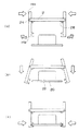
図2には、本発明の第一実施形態に係る保護部材の動作が示されている。 FIG. 2 shows the operation of the protective member according to the first embodiment of the present invention.
保護部材10を作業者が保持する際には脚部14の端部14aを押圧するようにして保持することで、図2(a)のように白矢印方向に端部14aが押され、14cを支点として14bを外側に(黒矢印方向)広げる力が発生する。
When the worker holds the
そのままの状態を保ち、図2(b)のように端部14bを基板20の縁部21に嵌合する位置まで移動させる。
The state is kept as it is, and the
次いで作業者が手を離せば保護部材10自体の弾性で14bは元の位置に戻り、図2(c)のように縁部21と嵌合する。以上のように、本実施形態では保護部材10を固定する際にビスなどの留め具や工具を一切必要とせず、簡単かつ正確、堅固に保護部材12を固定することができる。
Next, when the operator releases his / her hand, 14b returns to its original position due to the elasticity of the
図3には、本発明の第二実施形態に係る保護部材の構造が示されている。 FIG. 3 shows the structure of the protective member according to the second embodiment of the present invention.
図3のように、保護部材10bはカバー12に脚部14が軸24で揺動可能に支持されており、脚部14はバネ26で端部14bが閉じる方向に付勢されている。
As shown in FIG. 3, the
図4には、本発明の第二実施形態に係る保護部材の動作が示されている。 FIG. 4 shows the operation of the protective member according to the second embodiment of the present invention.
前述のように脚部14は端部14bが閉じる方向に付勢されているので、そのままでは手を離すと端部14b側が内側になる方向に閉じてしまい、使いにくい。
As described above, since the
そこで図4(a)のように、脚部14が閉じてしまわないようにカバー12にストッパ28を設け、バネ26による圧力を受け止める構造としてもよい。
Therefore, as shown in FIG. 4A, a
本実施形態においても、使用時には作業者が脚部14の端部14aを押圧するようにして保持することで、図4(a)のように白矢印方向に端部14aが押され、軸24を支点として14bを外側に(黒矢印方向)広げる力が発生する。
Also in this embodiment, when the operator presses and holds the
そのままの状態を保ち、図4(b)のように端部14bを基板20の縁部21に嵌合する位置まで移動させる。
The state is kept as it is, and the
次いで作業者が手を離せばバネ26の弾性で14bは元の位置に戻り、図4(c)のように縁部21と嵌合する。以上のように、本実施形態では保護部材10bを固定する際にビスなどの留め具や工具を一切必要とせず、簡単かつ正確、堅固に保護部材10bを固定することができる。
Next, when the operator releases his / her hand, 14b returns to its original position due to the elasticity of the
また、第一、第二実施形態で共通の特徴として、近年のコンパクト化が進んだ機械内部では基板20上の被保護部材22近辺にも部品が密集しているなどの理由で作業者の手が入りにくい状況が考えられるが、本発明の保護部材であれば作業のための空間なしで装着可能なので、ドライバやサムスクリューを使用する方法に比較して格段に作業性が優れている。
In addition, as a feature common to the first and second embodiments, an operator's hand is because the parts are densely arranged near the protected
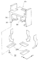
図5には、本発明の第三実施形態に係る保護部材の動作が示されている。 FIG. 5 shows the operation of the protective member according to the third embodiment of the present invention.
図5に示すように、保護部材10cには2つの脚部14に加えて3番目の脚部34を追加し、3方向から保護部材10cを固定する構造である。
As shown in FIG. 5, in addition to the two
脚部14,34によって3方向から固定するので堅固であり、かつ取付けの際に方向を間違える恐れのない、いわゆるフールプルーフ構造とすることができる。
Since it is fixed from the three directions by the
固定の際には3方向から押圧してもよいが、脚部34はあえて可動とせず基板20と嵌合させる構造としてもよい。その際には脚部34が基板20に嵌合する方向、つまり図5のY方向に位置決めが必要となるので、図5のように4番目の脚部30を設け、先端に突起32を設ける。
Although the pressing may be performed from three directions at the time of fixing, the
この突起32は基板20の位置決め穴36に嵌合する。すなわち、脚部14および脚部34を取付け穴21bに嵌合し、脚部14により図5のX方向の位置決めがなされた後、脚部34を取付け穴21bに挿入、突起32を位置決め穴36に嵌合すれば簡単に正確な位置合わせを行うことができる。
The
本実施形態によれば、保護部材10cを固定する際にビスなどの留め具や工具を一切必要とせず、簡単かつ正確、堅固に保護部材10cを固定することができる。
According to this embodiment, when fixing the
さらに、第一、第二実施形態で共通の特徴すなわち作業のための空間なしで装着可能なため、ドライバやサムスクリューを使用する方法に比較して格段に作業性が優れている点に加えて、位置決め穴36と突起32を用いることで手探りでも正確な位置合わせが容易に行える点が特徴であり、基板の裏側に手を回して作業を行う際などの作業性は特に優れている。
In addition to the features that are common to the first and second embodiments, that is, the work can be installed without a space for work, in addition to the point that the workability is much better than the method using a driver or thumb screw. The use of the
10 保護部材
12 カバー
14 脚部
16 突起
20 基板
22 被保護部材
24 軸
26 バネ
32 突起
36 位置決め穴
DESCRIPTION OF
Claims (3)
前記カバーの両端部から前記被取付部材に向かって延設され、前記被保護部材を跨いで両側面を囲い、先端部に設けられた固定部材で前記被取付部材の裏表を挟持する脚部と、
前記カバーに設けられた配線ホルダと、
を有し、
前記脚部は前記カバーを間に置いて一方を開閉させると他方が閉開する、板状に形成された脚板であり、
前記カバーと前記被保護部材との間に空間を設けた状態で前記脚部が前記被取付部材に係止されることを特徴とする保護部材。
A cover that covers a protected member that is a movable member attached to the attached member;
Legs extending from both ends of the cover toward the attached member, surrounding both sides across the protected member, and sandwiching the front and back of the attached member with a fixing member provided at the distal end portion; ,
A wiring holder provided on the cover;
Have
The leg portion is a leg plate formed in a plate shape, with the cover interposed therebetween and opening and closing one side and the other closing and opening,
The protection member, wherein the leg is locked to the attached member in a state where a space is provided between the cover and the protected member.
The protection member according to claim 1, wherein the leg plate is swingably supported by the cover and is urged in an opening direction or a closing direction by an elastic member.
The protection member according to claim 1, wherein the leg plate is integrally formed with the cover and is elastically deformed to open and close .
Priority Applications (1)
| Application Number | Priority Date | Filing Date | Title |
|---|---|---|---|
| JP2004059278A JP4380366B2 (en) | 2004-03-03 | 2004-03-03 | Protective member |
Applications Claiming Priority (1)
| Application Number | Priority Date | Filing Date | Title |
|---|---|---|---|
| JP2004059278A JP4380366B2 (en) | 2004-03-03 | 2004-03-03 | Protective member |
Publications (2)
| Publication Number | Publication Date |
|---|---|
| JP2005253180A JP2005253180A (en) | 2005-09-15 |
| JP4380366B2 true JP4380366B2 (en) | 2009-12-09 |
Family
ID=35033137
Family Applications (1)
| Application Number | Title | Priority Date | Filing Date |
|---|---|---|---|
| JP2004059278A Expired - Fee Related JP4380366B2 (en) | 2004-03-03 | 2004-03-03 | Protective member |
Country Status (1)
| Country | Link |
|---|---|
| JP (1) | JP4380366B2 (en) |
Families Citing this family (2)
| Publication number | Priority date | Publication date | Assignee | Title |
|---|---|---|---|---|
| GB0613205D0 (en) * | 2006-07-03 | 2006-08-09 | Dage Prec Ind Ltd | High speed test cartridge |
| SE538491C2 (en) * | 2015-03-17 | 2016-08-02 | Roxtec Ab | Seal |
-
2004
- 2004-03-03 JP JP2004059278A patent/JP4380366B2/en not_active Expired - Fee Related
Also Published As
| Publication number | Publication date |
|---|---|
| JP2005253180A (en) | 2005-09-15 |
Similar Documents
| Publication | Publication Date | Title |
|---|---|---|
| JP4433036B2 (en) | Electronic module and electronic device | |
| JP2012171114A (en) | Thermal printer | |
| JP4380366B2 (en) | Protective member | |
| JP4684340B2 (en) | Molded motor | |
| JP6611504B2 (en) | Cable holding structure and image forming apparatus | |
| JP6372006B2 (en) | Temporary placement structure for sub-cover | |
| JP4644502B2 (en) | Substrate support device and image forming apparatus | |
| JP5045079B2 (en) | Electric wire holder | |
| JP2009110996A (en) | Harness guide | |
| JP5116028B2 (en) | Cable guide | |
| JP2008021804A (en) | Component mounting structure | |
| JP2017217859A (en) | Image formation device | |
| KR101339146B1 (en) | Control box for sewing machine | |
| JP4173872B2 (en) | Enclosure | |
| JP2009068554A (en) | Member installing structure and image formation device | |
| JP6617093B2 (en) | PCB removal jig | |
| JP6413812B2 (en) | Built-in component mounting structure and control device | |
| JP2014192062A (en) | Connector separation hindering device | |
| JP6076154B2 (en) | Instrument unit | |
| JP4475265B2 (en) | Cover mounting structure | |
| JP5930198B2 (en) | Electronic equipment with terminal block | |
| JP2005037706A (en) | Image forming apparatus | |
| JP2022035844A (en) | Portable device | |
| JP2022017130A (en) | Electronic apparatus, harness arrangement structure, and harness arrangement tool | |
| JP5142688B2 (en) | clip |
Legal Events
| Date | Code | Title | Description |
|---|---|---|---|
| A621 | Written request for application examination |
Free format text: JAPANESE INTERMEDIATE CODE: A621 Effective date: 20070221 |
|
| A977 | Report on retrieval |
Free format text: JAPANESE INTERMEDIATE CODE: A971007 Effective date: 20080926 |
|
| A131 | Notification of reasons for refusal |
Free format text: JAPANESE INTERMEDIATE CODE: A131 Effective date: 20081014 |
|
| A521 | Written amendment |
Free format text: JAPANESE INTERMEDIATE CODE: A523 Effective date: 20081215 |
|
| A131 | Notification of reasons for refusal |
Free format text: JAPANESE INTERMEDIATE CODE: A131 Effective date: 20090609 |
|
| A521 | Written amendment |
Free format text: JAPANESE INTERMEDIATE CODE: A523 Effective date: 20090807 |
|
| TRDD | Decision of grant or rejection written | ||
| A01 | Written decision to grant a patent or to grant a registration (utility model) |
Free format text: JAPANESE INTERMEDIATE CODE: A01 Effective date: 20090901 |
|
| A01 | Written decision to grant a patent or to grant a registration (utility model) |
Free format text: JAPANESE INTERMEDIATE CODE: A01 |
|
| A61 | First payment of annual fees (during grant procedure) |
Free format text: JAPANESE INTERMEDIATE CODE: A61 Effective date: 20090914 |
|
| FPAY | Renewal fee payment (event date is renewal date of database) |
Free format text: PAYMENT UNTIL: 20121002 Year of fee payment: 3 |
|
| R150 | Certificate of patent or registration of utility model |
Ref document number: 4380366 Country of ref document: JP Free format text: JAPANESE INTERMEDIATE CODE: R150 Free format text: JAPANESE INTERMEDIATE CODE: R150 |
|
| FPAY | Renewal fee payment (event date is renewal date of database) |
Free format text: PAYMENT UNTIL: 20121002 Year of fee payment: 3 |
|
| FPAY | Renewal fee payment (event date is renewal date of database) |
Free format text: PAYMENT UNTIL: 20131002 Year of fee payment: 4 |
|
| LAPS | Cancellation because of no payment of annual fees |