JP4374591B2 - Apparatus for aligning seat skin to seat pad of automotive seat - Google Patents
Apparatus for aligning seat skin to seat pad of automotive seat Download PDFInfo
- Publication number
- JP4374591B2 JP4374591B2 JP2003091065A JP2003091065A JP4374591B2 JP 4374591 B2 JP4374591 B2 JP 4374591B2 JP 2003091065 A JP2003091065 A JP 2003091065A JP 2003091065 A JP2003091065 A JP 2003091065A JP 4374591 B2 JP4374591 B2 JP 4374591B2
- Authority
- JP
- Japan
- Prior art keywords
- seat
- skin
- pad
- workpiece
- work
- Prior art date
- Legal status (The legal status is an assumption and is not a legal conclusion. Google has not performed a legal analysis and makes no representation as to the accuracy of the status listed.)
- Expired - Fee Related
Links
- 238000009958 sewing Methods 0.000 claims description 34
- 230000000630 rising effect Effects 0.000 claims description 10
- 238000000034 method Methods 0.000 claims description 8
- 239000000463 material Substances 0.000 claims description 3
- 230000013011 mating Effects 0.000 claims 1
- 238000010586 diagram Methods 0.000 description 6
- 238000004519 manufacturing process Methods 0.000 description 4
- 238000003475 lamination Methods 0.000 description 2
- 125000002066 L-histidyl group Chemical group [H]N1C([H])=NC(C([H])([H])[C@](C(=O)[*])([H])N([H])[H])=C1[H] 0.000 description 1
- 239000000853 adhesive Substances 0.000 description 1
- 230000001070 adhesive effect Effects 0.000 description 1
- 230000001174 ascending effect Effects 0.000 description 1
- 238000005452 bending Methods 0.000 description 1
- 239000011230 binding agent Substances 0.000 description 1
- 230000000694 effects Effects 0.000 description 1
- 238000010438 heat treatment Methods 0.000 description 1
- 238000009434 installation Methods 0.000 description 1
- 238000009940 knitting Methods 0.000 description 1
- 238000010030 laminating Methods 0.000 description 1
- 238000002844 melting Methods 0.000 description 1
- 230000008018 melting Effects 0.000 description 1
- 238000003825 pressing Methods 0.000 description 1
Images


Landscapes
- Seats For Vehicles (AREA)
- Automobile Manufacture Line, Endless Track Vehicle, Trailer (AREA)
Description
【0001】
【発明の属する技術分野】
本発明は、自動車用シートのシートフレームを組み付けたシートパッドに対して、立体形に縫製したシート表皮を被せてワークとし、シート表皮をシートパッドに貼り合せるに先立って、シート表皮の座面表皮と側面表皮との縫製ラインをシートパッドの前方に隆起する左右の稜線に形状合せする装置に関するものである。
【0002】
【従来の技術】
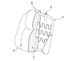
一般に、自動車用シートのシートバックを例示すると、図9で示すようにシートバックフレームFをバックパットPの背後に組み付け、立体形の袋状に縫製したシート表皮CをバックパットPに被せた後に、シート表皮Cの内面側に塗布した接着剤を加熱溶融させてシート表皮をバックパッドPの座面部分に圧着することにより、シート表皮CをバックパッドPに形状合わせする仕様のものがある。
【0003】
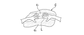
そのシート表皮CをバックパッドPに被せた状態では、図10で示すようにシート表皮CをバックパッドPの後部側に引張るテンションが掛かることから、座面表皮c1がバックパッドPの座面部分から浮き上がり、シート表皮Cの座面表皮c1と側面表皮c2との縫製ラインLがパックパッドPの後部側にずれてしまう。
【0004】
従来、シート表皮の貼合せ工程では、シート表皮CをバックパッドPに貼り合せるに先立って、図11で示すように作業員が手作業でシート表皮Cの座面表皮c1と側面表皮c2との縫製ラインLをバックパッド(図示せず)の前方に隆起する左右の稜線に形状合せすることが行われている。但し、この形状合せを行なっても、作業員がシート表皮から手を離すと、縫製ラインがシート表皮のテンションにより戻ってしまう。
【0005】
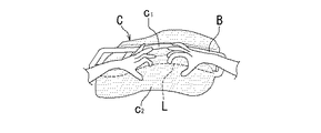
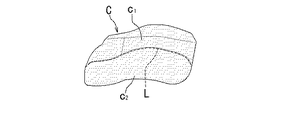
そのため、図12で示すようにシート表皮の貼合せ工程に備え付けられている溝付けバーBにより、シート表皮Cの座面部分と土手面部分との境目を上側から押え付け、作業員がシート表皮Cの縫製ラインLを手作業で改めてバックパッド(図示せず)の稜線に合せ、シート表皮Cをバックパッドに貼り合せることから、図13で示すようにシート表皮Cの縫製ラインLがバックパッドの稜線に合うよう形状保形することが行われている。
【0006】
上述したようなシート表皮の貼合せでは、極めて非能率的な手間の掛かる作業が必要とされる。また、作業員がシート表皮を手作業で引張るときに、縫製ラインの位置合わせする基準がなく、形状合せが任意に決定されていることから品質の安定化を図れない。
【0007】
【発明が解決しようとする課題】
本発明は、作業員がシート表皮を手で引張ってシート表皮の縫製ラインをシートパッドの稜線に合わせる作業を不要とし、また、再調整作業も省けることから、シート表皮の縫製ラインをバックパッドの稜線に能率よく合わせられて品質の安定化も図れる自動車用シートのシートパッドに対するシート表皮の形状合せ装置を提供することを目的とする。
【0008】
【課題を解決するための手段】
本発明の請求項1に係る自動車用シートのシートパッドに対するシート表皮の形状合せ装置においては、シートフレームを組み付けたシートパッドに対し、立体形に縫製したシート表皮を被せてワークとし、シート表皮をシートパッドに貼り合せるに先立って、シート表皮の座面表皮と側面表皮との縫製ラインをシートパッドの前方に隆起する左右の稜線に形状合せするもので、
座面相当部分を上側に向けてワークを位置決め載置するセット台と、セット台に載置したワークを上側から押込み支持するワーク押えバーと、該ワークをセット台の板面寄りで左右両側から抱込み支持するワーク抱えアームとを備え、
ワーク抱えアームは、シートパッドの稜線と略相応する軸曲げ形状を有する左右の支軸部と、支軸部を左右に分割可能な接続カプラを備えて支軸相互を片軸端で連結する横梁部とからなり、アーム全体を上下にストローク動する駆動シリンダで保持し、該駆動シリンダの上昇ストロークにより、ワークを左右の支軸部で両側からすり上げてシート表皮の縫製ラインをシートパッドの稜線に合わせて保形する治具とし、且つ、アーム全体を該駆動シリンダより取外し自在に備え、シート表皮の縫製ラインをシートパッドの稜線に合わせたワークを左右の支軸部で両側から抱え込んだままでアーム全体を駆動シリンダより取り外し、ワークをシートパッドに対するシート表皮の貼合せ工程に保形させて転送する冶具として備え付けることにより構成されている。
【0009】
本発明の請求項2に係る自動車用シートのシートパッドに対するシート表皮の形状合せ装置においては、シート表皮に対する摩擦力を有する材質の軸線カバーで被覆した支軸部を備え付けることにより構成されている。
【0010】
本発明の請求項3に係る自動車用シートのシートパッドに対するシート表皮の形状合せ装置においては、シート表皮に設けられるヘッドレストステーの通し穴よりシートフレームに設けられるヘッドレストステーの立付けホルダーに差し込み、ヘッドレストステーの通し穴とヘッドレストステーの立付けホルダーとを位置合わせする補助具を備え付けることにより構成されている。
【0011】
【発明の実施の形態】
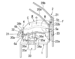
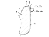
以下、図1〜図8を参照して説明すると、図1で示す実施の形態は、図9で示すものと同様な自動車用シートのシートバックを組み立てるにあたり、シートバックフレームFを組み付けたバックパッドPに対し、シート表皮Cを被せてワークWとし、シート表皮CをバックパッドPに貼り合せるに先立って、シート表皮Cの縫製ラインLをバックパッドPの稜線Rと左右共に形状合せするものとして適用されている。このシートバックには、ヘッドレスト(図示せず)が着脱自在に備え付けられる。
【0012】
そのシート表皮Cは、所定の平面形状に裁断した座面表皮c1と側面表皮c2とを縫い合せると共に、背面表皮(図示せず)を縫い合せて下部側を開放した立体形の袋状に縫製されている。シート表皮Cには、ヘッドレストステーの通し穴(図1中図示せず、図8中の符号「H」参照)が設けられている。また、シートバックフレームFにはヘッドレストステーの立付けホルダー(図1中図示せず、図8中の符号「S」参照)が設けられている。
【0013】
そのシート表皮の形状合せに適用する装置としては、座面部分を上側に向けてワークWを位置決め載置するセット台1と、セット台1に載置したワークWを上側から押込み支持するワーク押えバー2と、ワークWをセット台1の板面寄りで左右両側から抱込み支持するワーク抱えアーム3と、ヘッドレストステーの通し穴よりヘッドレストステーの立付けホルダーに差し込む補助具4とを備えて構成されている。
【0014】
セット台1は、作業員によるワークWの持込み側を前側とすると、シートバックフレームFのブラケットプレート(符号なし)が突出する側を奥側としてワークWを載置するよう設計されている。このセット台1をベースにし、ワーク押えバー2,ワーク抱えアーム3を含む後述する各種の機構部が取付け装備されている。
【0015】
ワーク押えバー2は、シート表皮Cの座面部分と土手面部分との境目を目安にし、ワークWを前寄り上部から押え付ける左右対の押えバー20a,20bを備えている。この押えバー20a,20bは、軸基部を回転支軸21の軸線上に連結固定し、回転支軸21をセット台1の奥側で左右の隅部に立付け設置する一対のスタンド脚部22a,22bで軸承支持し、更に、スタンド脚部22a,22bの略中央位置でセット台1の奥側に立付け設置する駆動シリンダ23を回転支軸21とリンク連結し、駆動シリンダ23の上下ストロークにより前倒れ乃至は跳上げ動可能に備え付けられている。
【0016】
ワーク抱えアーム3は、左右の支軸部30a,30bと、支軸30a,30b相互を片軸端で連結する横梁部31とから組み立てられている。支軸部30a,30bは、バックパッドPの稜線Rと略相応する軸曲げ形状を有する。即ち、ワークWがシートバックフレームFのブラケットプレートが突出する側を奥側として載置されることから、座者の腰部支持相当部分を頂点とする略への字状に軸曲げされている。横梁部31は、ネジ止め乃至は外し自在な接続カプラ32を軸線上に備えて支軸部30a,30bを左右に分割可能に連結されている。
【0017】
アーム全体は、上下にストローク動する駆動シリンダ33で保持されている。駆動シリンダ33は、左右対(片側のみ図示)でセット台1の両側部に立付け装備されている。この駆動シリンダ33の上昇ストロークにより、ワーク抱えアーム3は、ワークWを左右の支軸部30a,30bで両側からすり上げてシート表皮Cの縫製ラインLをバックパッドPの稜線Rに合わせて保形する治具として備え付けられている。
【0018】
駆動シリンダ33には、アーム全体のホルダープレート34a,34bが水平姿勢を保つようロッド端に取り付けて備えられている。このホルダープレート34a,34bには、立上りパイプ35a,35a’、35b,35b’が二本ずつ板面上に備え付けられている。一方、支軸部30a,30bには立上りパイプ35a,35a’、35b,35b’と抜差し自在な立付け軸部36a,36a’、36b,36b’が二本ずつ下方に向けて装着されている。
【0019】
この構成から、ワーク抱えアーム3は立付け軸部36a,36a’、36b,36b’を含むアーム全体を駆動シリンダ33より取外し自在に備え、シート表皮Cの縫製ラインLをバックパッドPの稜線Rに合わせたワークWを左右の支軸部30a,30bで両側から抱え込んだまま、ワークWをシートパッドに対するシート表皮の貼合せ工程に保形させて転送する冶具として備え付けられている。
【0020】
補助部4は、ヘッドレストステーの通し穴よりヘッドレストステーの立付けホルダーに差し込む左右対の嵌合せ軸部4a,4bと、嵌合せ軸部4a,4bを連結保持する取手軸部4cとから組み立てられている。この他に、ワーク抱えアーム3にはシート表皮に対する摩擦力を有するゴム材質の軸線カバー37a,37bで被覆した支軸部30a,30bが備え付けられている。
【0021】
上述した構成に加えて、ワークWをセット台1の板面上に位置決め載置し、また、補助具4を位置決め保持する付属設備が設けられている。その付属設備としては、シートバックフレームFのブラケットプレートをピン止め支持する受止めプレート5a,5bがワーク押えバー2のスタンド脚部22a,22bより前方に張り出すよう設けられている。また、補助具4を取手軸部4cで掛止め支持する左右対の立上りフレーム6a,6bがセット台1の前側に立付け装着されている。
【0022】
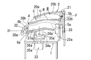
このように構成するシートパッドに対するシート表皮の形状合せ装置では、図2で示すように駆動シリンダ33を下降状態に保ってワークWをセット台1の板面上に載置する。その際、補助具4の嵌合せ軸部4a,4bをヘッドレストステーの通し穴よりヘッドレストステーの立付けホルダーに差し込むことから、少なくともシート表皮Cの上部側が形状合わせされているが、シート表皮Cの座面表皮c1と側面表皮c2との縫製ラインLがパックパッドPの後部側にずれた状態となっている。
【0023】
そのワークWは、シートバックフレームFのブラケットプレートを受止めプレート5a,5bでピン止め支持し、また、補助具4の取手軸部4cを立上りフレーム6a,6bに掛止め支持することから、全体がセット台1の板面上に位置決め載置される。このワークWをセット台1の板面上に位置決め載置すると、図3で示すようにワーク抱えアーム3が支軸部30a(30b)によりワークWをセット台1の板面寄りで左右両側から抱込み支持する。
【0024】
そのワークWをセット台1の板面上に位置決め載置した後、図4で示すように駆動シリンダ23を上昇ストロークさせてワーク押えバー2を前倒しし、シート表皮Cの座面部分と土手面部分との境目を目安に、ワークWを前部寄り上部から左右対の押えバー20a,20bで押え付ける。ワークWを押えバー20a,20bで上側から押え付けると、ワークWは次の駆動シリンダ33による上昇ストロークに伴って浮き上がらないようセット台1の板面上に確実に位置決め載置される。
【0025】
ワークWを押えバー20a,20bで上側から押え付けた後、次に、図5で示すように作動シリンダ33を上昇ストロークさせる。その作動シリンダ33の上昇ストロークに伴っては、ワーク抱えアーム3の支軸部30a,30bがワークWを両側からすり上げる。この際、ワークWが押えバー20a,20bで押え付けられていることも加わって、図6で示すようにシート表皮Cが縫製ラインLをバックパッドPの稜線Rに合わせるようすり上げられる。
【0026】
そのワーク抱えアーム3の支軸部30a,30bは、バックパッドPの稜線Rと略相応する軸曲げ形状を有するため、シート表皮Cの縫製ラインLを全長に亘ってバックパッドPの稜線Rに合わせられる。また、ワーク抱えアーム3の支軸部30a,30bにはシート表皮に対する摩擦力を有するゴム材質の軸線カバー37a,37bが被されているため、シート表皮Cを確実にすり上げてシート表皮Cの縫製ラインLをバックパッドPの稜線Rに正確に合わせられる。
【0027】
そのシート表皮Cの縫製ラインLをバックパッドPの稜線Rに合わせると、シート表皮Cの座面表皮c1が座面部分と土手面部分との境目を保つようバックパッドPの内側にずれ込んでバックパッドPの座面部分と馴染み保形する。この際に、少なくともシート表皮Cの上部側が補助具4で形状合わせされているため、シート表皮Cの座面部分と土手面部分との境目を保つようバックパッドPの内側にずれ込ませてバックパッドPの座面部分に対する馴染み保形を良好に保てる。
【0028】
また、ワーク抱えアーム3の支軸部30a,30bがバックパッドPの稜線Rにまですり上がると、バックパッドPの平面積が背部側よりも前部側で多少広がっているところから、支軸部30a,30bがワークWを両側から抱込み保持することによりシート表皮Cの縫製ラインLをバックパッドPの稜線Rに合わせて保てる。
【0029】
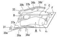
その縫製ラインLの合わせを終了すると、図7で示すようにワーク押えバー2を上方に跳上げ待避させてから、ワークWを両側から抱込み保持したワーク抱えアーム3を含めて全体をセット台1から取り外す。このワークWの取り外しは、支軸部30a,30bの立付け軸部36a,36a’、36b,36b’をホルダープレート34a,34bの立上りパイプ35a,35a’、35b,35b’から抜き出すことにより容易に行なえる。
【0030】
そのワークWは、ワーク抱えアーム3で抱込み保持したまま、シートパッドに対するシート表皮の貼合せ工程に転送する。このシート表皮の貼合せ工程では、図8で示すようにワークWをセット型Tに載置し、シート表皮Cの座面部分と土手面部分との境目を溝付けバーBで上側から押え付けてから、ワーク抱えアーム3をワークWから取り外す。
【0031】
そのワーク抱えアーム3の取外しは、接続カプラ32を雄,雌ネジによる螺着外しで離脱させて横梁部31から支軸部30a,30bを左右に分離することから容易に行なえる。ワーク抱えアーム3の取外し状態では、シート表皮Cの座面部分と土手面部分との境目が溝付けバーBで上側から押え付けられているため、シート表皮Cの縫製ラインLをバックパッドPの稜線Rに合わせた状態に保て、シート表皮Cを貼合せ型でバックパッドPに通常通り接着処理できる。
【0032】
その取り外したワーク抱えアーム3は、横梁部31から支軸部30a,30bを接続カプラ32で一体に組み立て、元のように支軸部30a,30bの立付け軸部36a,36a’、36b,36b’をホルダープレート34a,34bの立上りパイプ35a,35a’、35b,35b’に差し込むことによりセット台1に戻せばよい。また、補助具4はワークWをセット型Tに載置し、或いはシート表皮Cを接着処理してからワークWより取り外して元に戻せばよい。
【0033】
このようにシートパッドに対するシート表皮の貼合せ処理を行なうと、作業員がシート表皮を手で引張ってシート表皮の縫製ラインをシートパッドの稜線に合わせる作業を不要とし、また、再調整作業も省け、シート表皮の縫製ラインをバックパッドの稜線に能率よく合わせられて品質の安定化も図れる。
【0034】
上述した実施の形態は、着脱可能なヘッドレスト付きのシートバックを製造する場合に基づいて説明したが、ヘッドレスト一体のシートバックを製造するにも適用できる。また、シートバックに限らず、シートクッションを製造するのにも適用できる。これらヘッドレスト一体のシートバック並びにシートクッションを製造する場合、補助具4は不要となる。
【0035】
【発明の効果】
以上の如く、本発明の請求項1に係る自動車用シートのシートパッドに対するシート表皮の形状合せ装置に依れば、ワークを位置決め載置するセット台と、セット台に載置したワークを上側から押込み支持するワーク押えバーと、ワークをセット台の板面寄りで左右両側から抱込み支持するワーク抱えアームとを備え、ワーク抱えアームは、アーム全体を上下にストローク動する駆動シリンダで保持し、駆動シリンダの上昇ストロークにより、ワークを左右両側からすり上げてシート表皮の縫製ラインをシートパッドの稜線に合わせて保形する治具とし、且つ、アーム全体を駆動シリンダより取外し自在に備え、シート表皮の縫製ラインをシートパッドの稜線に合わせたワークを左右の支軸部で両側から抱え込んだままでアーム全体を駆動シリンダより取り外し、ワークをシートパッドに対するシート表皮の貼合せ工程に保形させて転送する冶具として備え付けることにより、作業員がシート表皮を手で引張ってシート表皮の縫製ラインをシートパッドの稜線に合わせる作業を不要とし、また、再調整作業も省け、シート表皮の縫製ラインをバックパッドの稜線に能率よく合わせられて品質の安定化も図れる。
【0036】
本発明の請求項2に係る自動車用シートのシートパッドに対するシート表皮の形状合せ装置に依れば、シート表皮に対する摩擦力を有する材質の軸線カバーで被覆した支軸部を備え付けることにより、シート表皮を確実にすり上げられてシート表皮の縫製ラインをバックパッドの稜線に正確に合わせられる。
【0037】
本発明の請求項3に係る自動車用シートのシートパッドに対するシート表皮の形状合せ装置に依れば、ヘッドレストステーの通し穴とヘッドレストステーの立付けホルダーとを位置合わせする補助具を備え付けることにより、ヘッドレストステーの通し穴とヘッドレストステーの立付けホルダーとを正確に位置合わせできると共に、少なくともシート表皮の上部側を補助具で形状合わせできるため、シート表皮の座面部分と土手面部分との境目を保つようバックパッドの内側にずれ込ませてバックパッドの座面部分に対する馴染み保形を良好に保てる。
【図面の簡単な説明】
【図1】本発明に係る自動車用シートのシートパッドに対するシート表皮の形状合せ装置をワークと共に示す説明図である。
【図2】図1の装置におけるワークのセット状態を示す説明図である。
【図3】図2のワークセットに伴うワーク抱えアームの組付状態を示す説明図である。
【図4】図2のワークセットに引き続くワーク押えバーの作動状態を示す説明図である。
【図5】図4のワーク押えに引き続くワーク抱えアームのすり上げ作動状態を示す説明図である。
【図6】図5のワーク抱えアームによるワークのすり上げ状態を示す説明図である。
【図7】図5のワークすり上げ引き続くワークの取外し状態を示す説明図である。
【図8】図7のワークをシート表皮の貼合せ型に載置したセット状態を示す説明図である。
【図9】一般例に係る着脱ヘッドレスト付きの自動車用シートバックを部分断面で示す説明図である。
【図10】通常のシート表皮をシートパッドに被せた組付け状態を示す説明図である。
【図11】従来例に係るシート表皮の貼合せ前に行われるシートパッドに対するシート表皮の形状合せ作業を示す説明図である。
【図12】従来例に係るシート表皮の貼合せ工程におけるシートパッドに対するシート表皮の形状合せ作業を示す説明図である。
【図13】通常のシートパッドに対するシート表皮の形状合せ状態を示す説明図である。
【符号の説明】
W ワーク
F シートフレーム
P シートパッド
R シートパッドの稜線
C シート表皮
c1 座面表皮
c2 座面表皮
L シート表皮の縫製ライン
1 ワークのセット台
2 ワーク押えバー
3 ワーク抱えアーム
30a,30b 支軸部
31 横梁部
32 接続カプラ
33 駆動シリンダ
37a,37b 軸線カバー
4 補助具[0001]
BACKGROUND OF THE INVENTION
The present invention provides a seat pad on which a seat frame of an automobile seat is assembled and covers a seat cover that is sewn in a three-dimensional shape to form a work, and prior to bonding the seat cover to the seat pad, the seat cover of the seat cover The present invention relates to a device that matches the shape of the sewing line between the knitting and the side skin to the left and right ridges that protrude in front of the seat pad.
[0002]
[Prior art]
In general, a seat back of an automobile seat is exemplified. After the seat back frame F is assembled behind the back pad P as shown in FIG. 9 and the seat skin C sewn in a three-dimensional bag shape is put on the back pad P, There is a specification in which the sheet skin C is shaped to the back pad P by heating and melting the adhesive applied to the inner surface side of the sheet skin C and pressing the sheet skin to the seating surface portion of the back pad P.
[0003]
In a state where covered the seat upholstery C back pad P, the seat upholstery C from pulling tension is applied to the rear side of the back pad P, as shown in Figure 10, the bearing surface bearing surface of the skin c 1 is the back pad P As a result, the sewing line L of the seat skin C 1 and the side skin c 2 of the seat skin C is shifted to the rear side of the pack pad P.
[0004]
Conventionally, in the process of pasting the sheet skin, prior to pasting the sheet skin C to the back pad P, as shown in FIG. 11, the worker manually performs the seating skin c 1 and the side skin c 2 of the sheet skin C. The shape of the sewing line L is aligned with the left and right ridges that protrude in front of a back pad (not shown). However, even if this shape matching is performed, if the worker releases his / her hand from the seat skin, the sewing line returns due to the tension of the seat skin.
[0005]
Therefore, as shown in FIG. 12, the grooved bar B provided for the sheet skin bonding step holds the boundary between the seat surface portion and the bank surface portion of the sheet skin C from above, and the worker can Since the sewing line L of C is manually aligned with the ridgeline of the back pad (not shown) and the sheet skin C is bonded to the back pad, the sewing line L of the seat skin C is back pad as shown in FIG. The shape is maintained to match the ridgeline.
[0006]
Lamination of the sheet skin as described above requires a very inefficient and time-consuming work. Further, when the operator pulls the seat skin manually, there is no standard for aligning the sewing line, and the shape alignment is arbitrarily determined, so the quality cannot be stabilized.
[0007]
[Problems to be solved by the invention]
The present invention eliminates the need for the operator to manually pull the seat skin and align the seat skin sewing line with the ridge of the seat pad, and also eliminates readjustment work. It is an object of the present invention to provide a sheet skin shape matching device for a seat pad of an automobile seat that can be efficiently matched to a ridgeline and can stabilize quality.
[0008]
[Means for Solving the Problems]
In the apparatus for aligning the seat skin to the seat pad of the automobile seat according to
A set base for positioning and placing the work with the seat surface equivalent part facing upward, a work presser bar for pushing and supporting the work placed on the set base from above, and the work from the left and right sides near the plate surface of the set base It has a work holding arm to hold and support,
The work holding arm is a horizontal beam that has left and right support shafts that have a bent shape that roughly corresponds to the ridgeline of the seat pad, and a connecting coupler that can divide the support shaft into left and right parts, and connects the support shafts at one end. The entire arm is held by a drive cylinder that moves up and down, and the workpiece is lifted from both sides by the left and right support shafts by the rising stroke of the drive cylinder, and the sewing line of the seat skin is ridged on the seat pad. The entire arm is detachable from the drive cylinder, and the workpiece with the seat skin sewing line aligned with the ridgeline of the seat pad is held from both sides by the left and right support shafts. The entire arm is removed from the drive cylinder, and the workpiece is mounted as a jig that retains the shape of the workpiece in the process of pasting the sheet skin to the seat pad and transfers it. It is.
[0009]
According to a second aspect of the present invention, there is provided an apparatus for aligning a seat skin with respect to a seat pad of an automobile seat, comprising a support shaft portion covered with an axis cover made of a material having a frictional force against the seat skin.
[0010]
In the apparatus for adjusting the shape of the seat cover to the seat pad of the automobile seat according to
[0011]
DETAILED DESCRIPTION OF THE INVENTION
1 to 8, the embodiment shown in FIG. 1 is a back pad in which a seat back frame F is assembled when assembling a seat back of an automobile seat similar to that shown in FIG. A sheet W is covered with a sheet skin C to form a workpiece W, and before the sheet skin C is bonded to the back pad P, the sewing line L of the sheet skin C is aligned with the ridge line R of the back pad P on both the left and right sides. Has been applied. A headrest (not shown) is detachably attached to the seat back.
[0012]
The seat skin C is a three-dimensional bag shape in which the seat surface skin c 1 and the side surface skin c 2 cut into a predetermined planar shape are sewn together, and the back side skin (not shown) is sewn to open the lower side. Is sewn. The seat skin C is provided with a through hole of the headrest stay (not shown in FIG. 1, refer to “H” in FIG. 8). Further, the seatback frame F is provided with a headrest stay standing holder (not shown in FIG. 1, refer to “S” in FIG. 8).
[0013]
As a device applied to the shape matching of the seat skin, a
[0014]
The set table 1 is designed so that the work W is placed with the side from which the bracket plate (not indicated) of the seat back frame F protrudes as the back side when the work W carry-in side by the worker is the front side. Based on this
[0015]
The
[0016]
The
[0017]
The entire arm is held by a
[0018]
The
[0019]
With this configuration, the
[0020]
The auxiliary portion 4 is assembled from a pair of left and right
[0021]
In addition to the above-described configuration, an auxiliary facility for positioning and holding the work W on the plate surface of the set table 1 and positioning and holding the auxiliary tool 4 is provided. As the accessory equipment, receiving
[0022]
In the sheet skin shape matching device for the seat pad configured as described above, the workpiece W is placed on the plate surface of the set table 1 while the
[0023]
The workpiece W is supported by pinning and supporting the bracket plate of the seat back frame F by the receiving
[0024]
After the workpiece W is positioned and placed on the plate surface of the
[0025]
After the work W is pressed from the upper side by the press bars 20a and 20b, the operating
[0026]
Since the
[0027]
When the sewing line L of the seat skin C is aligned with the ridge line R of the back pad P, the seat skin c 1 of the seat skin C is shifted to the inside of the back pad P so as to keep the boundary between the seat surface portion and the bank surface portion. Fits in shape with the back pad P seat surface. At this time, since at least the upper side of the seat skin C is shaped with the auxiliary tool 4, the back of the back pad P is shifted so as to keep the boundary between the seat surface portion and the bank surface portion of the seat skin C. The familiar shape with respect to the seating surface portion of the pad P can be maintained well.
[0028]
Further, when the
[0029]
When the alignment of the sewing line L is completed, as shown in FIG. 7, the
[0030]
The work W is transferred to the bonding process of the sheet skin to the seat pad while being held by the
[0031]
The
[0032]
The removed
[0033]
When the sheet cover is bonded to the seat pad in this way, the operator does not need to manually pull the sheet cover to align the seat cover sewing line with the ridge of the seat pad, and the readjustment can be omitted. The sewing line of the seat skin can be efficiently aligned with the ridgeline of the back pad, so that the quality can be stabilized.
[0034]
Although the above-described embodiment has been described based on the case of manufacturing a seat back with a detachable headrest, the embodiment can also be applied to manufacturing a seatback integrated with a headrest. Moreover, it is applicable not only to manufacturing a seat cushion but also to a seat cushion. When manufacturing a seat back and a seat cushion integrated with these headrests, the auxiliary tool 4 is not necessary.
[0035]
【The invention's effect】
As described above, according to the sheet skin shape matching device for the seat pad of the automobile seat according to
[0036]
According to the apparatus for aligning a seat skin with respect to a seat pad of an automobile seat according to
[0037]
According to the seat skin shape matching device for the seat pad of the automobile seat according to
[Brief description of the drawings]
FIG. 1 is an explanatory view showing a shape adjustment device for a seat skin with respect to a seat pad of an automobile seat according to the present invention together with a workpiece.
2 is an explanatory diagram showing a workpiece set state in the apparatus of FIG. 1; FIG.
FIG. 3 is an explanatory view showing an assembled state of a work holding arm associated with the work set of FIG. 2;
4 is an explanatory diagram showing an operation state of a work presser bar subsequent to the work set in FIG. 2; FIG.
5 is an explanatory diagram showing a lifting operation state of a workpiece holding arm subsequent to the workpiece presser of FIG. 4; FIG.
6 is an explanatory diagram showing a state in which a workpiece is lifted by the workpiece holding arm of FIG. 5;
7 is an explanatory diagram showing a workpiece removal state following the workpiece lifting shown in FIG. 5; FIG.
8 is an explanatory view showing a set state in which the work of FIG. 7 is placed on a sheet skin lamination mold. FIG.
FIG. 9 is an explanatory view showing, in partial cross section, an automobile seat back with a detachable headrest according to a general example.
FIG. 10 is an explanatory view showing an assembled state in which a normal seat cover is put on a seat pad.
FIG. 11 is an explanatory diagram showing a sheet skin shape matching operation with respect to a seat pad performed before pasting of the sheet skin according to a conventional example.
FIG. 12 is an explanatory view showing a sheet skin shape matching operation for a seat pad in a sheet skin bonding process according to a conventional example.
FIG. 13 is an explanatory view showing a state of matching the shape of the seat skin with respect to a normal seat pad.
[Explanation of symbols]
W Work F Seat frame P Seat pad R Seat pad edge C Seat skin c 1 Seat surface skin c 2 Seat surface skin L Seat
Claims (3)
座面部分を上側に向けてワークを位置決め載置するセット台と、セット台に載置したワークを上側から押込み支持するワーク押えバーと、該ワークをセット台寄りで左右両側から抱込み支持するワーク抱えアームとを備え、
ワーク抱えアームは、シートパッドの稜線と略相応する軸曲げ形状を有する左右の支軸部と、支軸部を左右に分割可能な接続カプラを備えて支軸相互を片軸端で連結する横梁部とからなり、アーム全体を上下にストローク動する駆動シリンダで保持し、該駆動シリンダの上昇ストロークにより、ワークを左右の支軸部で両側からすり上げてシート表皮の縫製ラインをシートパッドの稜線に合わせて保形する治具とし、且つ、アーム全体を該駆動シリンダより取外し自在に備え、シート表皮の縫製ラインをシートパッドの稜線に合わせたワークを左右の支軸部で両側から抱え込んだままでアーム全体を駆動シリンダより取り外し、ワークをシートパッドに対するシート表皮の貼合せ工程に保形させて転送する冶具として備え付けたことを特徴とする自動車用シートのシートパッドに対するシート表皮の形状合せ装置。A seat pad with a seat frame for an automobile seat is covered with a seat cover that is sewn in a three-dimensional shape to form a workpiece. A device for adjusting the shape of the sewing line to the left and right ridges that protrude in front of the seat pad,
A set stand for positioning and placing the work with the seat surface facing upward, a work holding bar for pushing and supporting the work placed on the set base from above, and holding the work from both the left and right sides near the set stand With a work holding arm,
The work holding arm is a horizontal beam that has left and right support shafts that have a bent shape that roughly corresponds to the ridgeline of the seat pad, and a connecting coupler that can divide the support shaft into left and right parts, and connects the support shafts at one end. The entire arm is held by a drive cylinder that moves up and down, and the workpiece is lifted from both sides by the left and right support shafts by the rising stroke of the drive cylinder, and the sewing line of the seat skin is ridged on the seat pad. The entire arm is detachable from the drive cylinder, and the workpiece with the seat skin sewing line aligned with the ridgeline of the seat pad is held from both sides by the left and right support shafts. The entire arm is removed from the drive cylinder, and the workpiece is mounted as a jig for transferring the shape of the workpiece to the sheet pad bonding process to the seat pad. Shape mating device for a seat skin for a seat pad for an automobile seat that.
Priority Applications (1)
| Application Number | Priority Date | Filing Date | Title |
|---|---|---|---|
| JP2003091065A JP4374591B2 (en) | 2003-03-28 | 2003-03-28 | Apparatus for aligning seat skin to seat pad of automotive seat |
Applications Claiming Priority (1)
| Application Number | Priority Date | Filing Date | Title |
|---|---|---|---|
| JP2003091065A JP4374591B2 (en) | 2003-03-28 | 2003-03-28 | Apparatus for aligning seat skin to seat pad of automotive seat |
Publications (2)
| Publication Number | Publication Date |
|---|---|
| JP2004290622A JP2004290622A (en) | 2004-10-21 |
| JP4374591B2 true JP4374591B2 (en) | 2009-12-02 |
Family
ID=33404533
Family Applications (1)
| Application Number | Title | Priority Date | Filing Date |
|---|---|---|---|
| JP2003091065A Expired - Fee Related JP4374591B2 (en) | 2003-03-28 | 2003-03-28 | Apparatus for aligning seat skin to seat pad of automotive seat |
Country Status (1)
| Country | Link |
|---|---|
| JP (1) | JP4374591B2 (en) |
Families Citing this family (2)
| Publication number | Priority date | Publication date | Assignee | Title |
|---|---|---|---|---|
| JP4886470B2 (en) * | 2006-10-31 | 2012-02-29 | 株式会社イノアックコーポレーション | Skin application device |
| CN114027659A (en) * | 2021-12-13 | 2022-02-11 | 浙江凯越家具制造有限公司 | Efficient waterproof outdoor woven rattan chair and production process thereof |
-
2003
- 2003-03-28 JP JP2003091065A patent/JP4374591B2/en not_active Expired - Fee Related
Also Published As
| Publication number | Publication date |
|---|---|
| JP2004290622A (en) | 2004-10-21 |
Similar Documents
| Publication | Publication Date | Title |
|---|---|---|
| KR101623165B1 (en) | Feeding and leveling method and system for a flexible pcb drilling machine | |
| JP4394611B2 (en) | Roof glass transfer jig | |
| CN219542033U (en) | Workbench for laser cutting | |
| JP4374591B2 (en) | Apparatus for aligning seat skin to seat pad of automotive seat | |
| CN206677462U (en) | A kind of manual telescopic detent mechanism | |
| CN217647825U (en) | Linkage type multi-station welding tool | |
| CN101171380A (en) | Embroidery frame support device | |
| JP2004322238A (en) | Rail drilling machine | |
| CN205368700U (en) | Sewing machine | |
| KR100904188B1 (en) | Rain force bar manufacturing device for car seat frame | |
| JPH06170459A (en) | Hemming press die and hemming method using the same | |
| CN210586787U (en) | Hollow necking die | |
| CN211542784U (en) | Printing device capable of printing stably | |
| CN220318210U (en) | Bed sheet ironing positioning structure | |
| CN222160607U (en) | Bag folding mechanism of bag opening sewing machine | |
| CN119347297B (en) | Fan impeller welding device | |
| CN220163441U (en) | Thermal transfer printer for noodle sleeve production | |
| CN112025536B (en) | Part clamping mechanism of honing system | |
| CN222986717U (en) | Shell applique auxiliary positioning equipment for mower production | |
| CN115385292B (en) | A mesh cloth assembly process for a seat frame | |
| CN113617902B (en) | Automatic adjustable upward pressing combined mechanism of bending machine | |
| CN222292973U (en) | Manipulator for printing machine | |
| KR102658421B1 (en) | Vehicle console cover fix device | |
| TWI279313B (en) | Apparatus for making document cover and method used thereby | |
| CN222242819U (en) | Shearing device convenient to adjust shearing length |
Legal Events
| Date | Code | Title | Description |
|---|---|---|---|
| A621 | Written request for application examination |
Free format text: JAPANESE INTERMEDIATE CODE: A621 Effective date: 20060228 |
|
| TRDD | Decision of grant or rejection written | ||
| A01 | Written decision to grant a patent or to grant a registration (utility model) |
Free format text: JAPANESE INTERMEDIATE CODE: A01 Effective date: 20090811 |
|
| A01 | Written decision to grant a patent or to grant a registration (utility model) |
Free format text: JAPANESE INTERMEDIATE CODE: A01 |
|
| A61 | First payment of annual fees (during grant procedure) |
Free format text: JAPANESE INTERMEDIATE CODE: A61 Effective date: 20090828 |
|
| R150 | Certificate of patent or registration of utility model |
Free format text: JAPANESE INTERMEDIATE CODE: R150 |
|
| FPAY | Renewal fee payment (event date is renewal date of database) |
Free format text: PAYMENT UNTIL: 20120918 Year of fee payment: 3 |
|
| FPAY | Renewal fee payment (event date is renewal date of database) |
Free format text: PAYMENT UNTIL: 20130918 Year of fee payment: 4 |
|
| R250 | Receipt of annual fees |
Free format text: JAPANESE INTERMEDIATE CODE: R250 |
|
| R250 | Receipt of annual fees |
Free format text: JAPANESE INTERMEDIATE CODE: R250 |
|
| LAPS | Cancellation because of no payment of annual fees |