JP4373014B2 - Method for applying adhesive coated film - Google Patents
Method for applying adhesive coated film Download PDFInfo
- Publication number
- JP4373014B2 JP4373014B2 JP2000594658A JP2000594658A JP4373014B2 JP 4373014 B2 JP4373014 B2 JP 4373014B2 JP 2000594658 A JP2000594658 A JP 2000594658A JP 2000594658 A JP2000594658 A JP 2000594658A JP 4373014 B2 JP4373014 B2 JP 4373014B2
- Authority
- JP
- Japan
- Prior art keywords
- film
- heat
- substrate
- pressure source
- pressure
- Prior art date
- Legal status (The legal status is an assumption and is not a legal conclusion. Google has not performed a legal analysis and makes no representation as to the accuracy of the status listed.)
- Expired - Fee Related
Links
Images


Classifications
-
- B—PERFORMING OPERATIONS; TRANSPORTING
- B32—LAYERED PRODUCTS
- B32B—LAYERED PRODUCTS, i.e. PRODUCTS BUILT-UP OF STRATA OF FLAT OR NON-FLAT, e.g. CELLULAR OR HONEYCOMB, FORM
- B32B37/00—Methods or apparatus for laminating, e.g. by curing or by ultrasonic bonding
- B32B37/10—Methods or apparatus for laminating, e.g. by curing or by ultrasonic bonding characterised by the pressing technique, e.g. using action of vacuum or fluid pressure
-
- B—PERFORMING OPERATIONS; TRANSPORTING
- B29—WORKING OF PLASTICS; WORKING OF SUBSTANCES IN A PLASTIC STATE IN GENERAL
- B29C—SHAPING OR JOINING OF PLASTICS; SHAPING OF MATERIAL IN A PLASTIC STATE, NOT OTHERWISE PROVIDED FOR; AFTER-TREATMENT OF THE SHAPED PRODUCTS, e.g. REPAIRING
- B29C63/00—Lining or sheathing, i.e. applying preformed layers or sheathings of plastics; Apparatus therefor
- B29C63/0065—Heat treatment
-
- B—PERFORMING OPERATIONS; TRANSPORTING
- B29—WORKING OF PLASTICS; WORKING OF SUBSTANCES IN A PLASTIC STATE IN GENERAL
- B29C—SHAPING OR JOINING OF PLASTICS; SHAPING OF MATERIAL IN A PLASTIC STATE, NOT OTHERWISE PROVIDED FOR; AFTER-TREATMENT OF THE SHAPED PRODUCTS, e.g. REPAIRING
- B29C63/00—Lining or sheathing, i.e. applying preformed layers or sheathings of plastics; Apparatus therefor
- B29C63/0073—Lining or sheathing, i.e. applying preformed layers or sheathings of plastics; Apparatus therefor of non-flat surfaces, e.g. curved, profiled
-
- B—PERFORMING OPERATIONS; TRANSPORTING
- B29—WORKING OF PLASTICS; WORKING OF SUBSTANCES IN A PLASTIC STATE IN GENERAL
- B29C—SHAPING OR JOINING OF PLASTICS; SHAPING OF MATERIAL IN A PLASTIC STATE, NOT OTHERWISE PROVIDED FOR; AFTER-TREATMENT OF THE SHAPED PRODUCTS, e.g. REPAIRING
- B29C63/00—Lining or sheathing, i.e. applying preformed layers or sheathings of plastics; Apparatus therefor
- B29C63/02—Lining or sheathing, i.e. applying preformed layers or sheathings of plastics; Apparatus therefor using sheet or web-like material
-
- B—PERFORMING OPERATIONS; TRANSPORTING
- B29—WORKING OF PLASTICS; WORKING OF SUBSTANCES IN A PLASTIC STATE IN GENERAL
- B29C—SHAPING OR JOINING OF PLASTICS; SHAPING OF MATERIAL IN A PLASTIC STATE, NOT OTHERWISE PROVIDED FOR; AFTER-TREATMENT OF THE SHAPED PRODUCTS, e.g. REPAIRING
- B29C65/00—Joining or sealing of preformed parts, e.g. welding of plastics materials; Apparatus therefor
- B29C65/02—Joining or sealing of preformed parts, e.g. welding of plastics materials; Apparatus therefor by heating, with or without pressure
- B29C65/14—Joining or sealing of preformed parts, e.g. welding of plastics materials; Apparatus therefor by heating, with or without pressure using wave energy, i.e. electromagnetic radiation, or particle radiation
- B29C65/1403—Joining or sealing of preformed parts, e.g. welding of plastics materials; Apparatus therefor by heating, with or without pressure using wave energy, i.e. electromagnetic radiation, or particle radiation characterised by the type of electromagnetic or particle radiation
-
- B—PERFORMING OPERATIONS; TRANSPORTING
- B32—LAYERED PRODUCTS
- B32B—LAYERED PRODUCTS, i.e. PRODUCTS BUILT-UP OF STRATA OF FLAT OR NON-FLAT, e.g. CELLULAR OR HONEYCOMB, FORM
- B32B37/00—Methods or apparatus for laminating, e.g. by curing or by ultrasonic bonding
- B32B37/0046—Methods or apparatus for laminating, e.g. by curing or by ultrasonic bonding characterised by constructional aspects of the apparatus
- B32B37/0053—Constructional details of laminating machines comprising rollers; Constructional features of the rollers
-
- B—PERFORMING OPERATIONS; TRANSPORTING
- B32—LAYERED PRODUCTS
- B32B—LAYERED PRODUCTS, i.e. PRODUCTS BUILT-UP OF STRATA OF FLAT OR NON-FLAT, e.g. CELLULAR OR HONEYCOMB, FORM
- B32B37/00—Methods or apparatus for laminating, e.g. by curing or by ultrasonic bonding
- B32B37/02—Methods or apparatus for laminating, e.g. by curing or by ultrasonic bonding characterised by a sequence of laminating steps, e.g. by adding new layers at consecutive laminating stations
- B32B37/025—Transfer laminating
-
- B—PERFORMING OPERATIONS; TRANSPORTING
- B32—LAYERED PRODUCTS
- B32B—LAYERED PRODUCTS, i.e. PRODUCTS BUILT-UP OF STRATA OF FLAT OR NON-FLAT, e.g. CELLULAR OR HONEYCOMB, FORM
- B32B37/00—Methods or apparatus for laminating, e.g. by curing or by ultrasonic bonding
- B32B37/04—Methods or apparatus for laminating, e.g. by curing or by ultrasonic bonding characterised by the partial melting of at least one layer
-
- B—PERFORMING OPERATIONS; TRANSPORTING
- B32—LAYERED PRODUCTS
- B32B—LAYERED PRODUCTS, i.e. PRODUCTS BUILT-UP OF STRATA OF FLAT OR NON-FLAT, e.g. CELLULAR OR HONEYCOMB, FORM
- B32B37/00—Methods or apparatus for laminating, e.g. by curing or by ultrasonic bonding
- B32B37/06—Methods or apparatus for laminating, e.g. by curing or by ultrasonic bonding characterised by the heating method
-
- B—PERFORMING OPERATIONS; TRANSPORTING
- B32—LAYERED PRODUCTS
- B32B—LAYERED PRODUCTS, i.e. PRODUCTS BUILT-UP OF STRATA OF FLAT OR NON-FLAT, e.g. CELLULAR OR HONEYCOMB, FORM
- B32B37/00—Methods or apparatus for laminating, e.g. by curing or by ultrasonic bonding
- B32B37/12—Methods or apparatus for laminating, e.g. by curing or by ultrasonic bonding characterised by using adhesives
-
- B—PERFORMING OPERATIONS; TRANSPORTING
- B32—LAYERED PRODUCTS
- B32B—LAYERED PRODUCTS, i.e. PRODUCTS BUILT-UP OF STRATA OF FLAT OR NON-FLAT, e.g. CELLULAR OR HONEYCOMB, FORM
- B32B39/00—Layout of apparatus or plants, e.g. modular laminating systems
-
- C—CHEMISTRY; METALLURGY
- C09—DYES; PAINTS; POLISHES; NATURAL RESINS; ADHESIVES; COMPOSITIONS NOT OTHERWISE PROVIDED FOR; APPLICATIONS OF MATERIALS NOT OTHERWISE PROVIDED FOR
- C09J—ADHESIVES; NON-MECHANICAL ASPECTS OF ADHESIVE PROCESSES IN GENERAL; ADHESIVE PROCESSES NOT PROVIDED FOR ELSEWHERE; USE OF MATERIALS AS ADHESIVES
- C09J7/00—Adhesives in the form of films or foils
- C09J7/20—Adhesives in the form of films or foils characterised by their carriers
- C09J7/22—Plastics; Metallised plastics
- C09J7/24—Plastics; Metallised plastics based on macromolecular compounds obtained by reactions involving only carbon-to-carbon unsaturated bonds
- C09J7/241—Polyolefin, e.g.rubber
-
- C—CHEMISTRY; METALLURGY
- C09—DYES; PAINTS; POLISHES; NATURAL RESINS; ADHESIVES; COMPOSITIONS NOT OTHERWISE PROVIDED FOR; APPLICATIONS OF MATERIALS NOT OTHERWISE PROVIDED FOR
- C09J—ADHESIVES; NON-MECHANICAL ASPECTS OF ADHESIVE PROCESSES IN GENERAL; ADHESIVE PROCESSES NOT PROVIDED FOR ELSEWHERE; USE OF MATERIALS AS ADHESIVES
- C09J7/00—Adhesives in the form of films or foils
- C09J7/20—Adhesives in the form of films or foils characterised by their carriers
- C09J7/22—Plastics; Metallised plastics
- C09J7/24—Plastics; Metallised plastics based on macromolecular compounds obtained by reactions involving only carbon-to-carbon unsaturated bonds
- C09J7/245—Vinyl resins, e.g. polyvinyl chloride [PVC]
-
- C—CHEMISTRY; METALLURGY
- C09—DYES; PAINTS; POLISHES; NATURAL RESINS; ADHESIVES; COMPOSITIONS NOT OTHERWISE PROVIDED FOR; APPLICATIONS OF MATERIALS NOT OTHERWISE PROVIDED FOR
- C09J—ADHESIVES; NON-MECHANICAL ASPECTS OF ADHESIVE PROCESSES IN GENERAL; ADHESIVE PROCESSES NOT PROVIDED FOR ELSEWHERE; USE OF MATERIALS AS ADHESIVES
- C09J7/00—Adhesives in the form of films or foils
- C09J7/20—Adhesives in the form of films or foils characterised by their carriers
- C09J7/22—Plastics; Metallised plastics
- C09J7/25—Plastics; Metallised plastics based on macromolecular compounds obtained otherwise than by reactions involving only carbon-to-carbon unsaturated bonds
-
- C—CHEMISTRY; METALLURGY
- C09—DYES; PAINTS; POLISHES; NATURAL RESINS; ADHESIVES; COMPOSITIONS NOT OTHERWISE PROVIDED FOR; APPLICATIONS OF MATERIALS NOT OTHERWISE PROVIDED FOR
- C09J—ADHESIVES; NON-MECHANICAL ASPECTS OF ADHESIVE PROCESSES IN GENERAL; ADHESIVE PROCESSES NOT PROVIDED FOR ELSEWHERE; USE OF MATERIALS AS ADHESIVES
- C09J7/00—Adhesives in the form of films or foils
- C09J7/30—Adhesives in the form of films or foils characterised by the adhesive composition
- C09J7/38—Pressure-sensitive adhesives [PSA]
-
- G—PHYSICS
- G09—EDUCATION; CRYPTOGRAPHY; DISPLAY; ADVERTISING; SEALS
- G09F—DISPLAYING; ADVERTISING; SIGNS; LABELS OR NAME-PLATES; SEALS
- G09F15/00—Boards, hoardings, pillars, or like structures for notices, placards, posters, or the like
- G09F15/02—Bills, posters, or the like therefor
-
- G—PHYSICS
- G09—EDUCATION; CRYPTOGRAPHY; DISPLAY; ADVERTISING; SEALS
- G09F—DISPLAYING; ADVERTISING; SIGNS; LABELS OR NAME-PLATES; SEALS
- G09F7/00—Signs, name or number plates, letters, numerals, or symbols; Panels or boards
- G09F7/02—Signs, plates, panels or boards using readily-detachable elements bearing or forming symbols
- G09F7/12—Signs, plates, panels or boards using readily-detachable elements bearing or forming symbols the elements being secured or adapted to be secured by self-adhesion, moisture, suction, slow-drying adhesive or the like
-
- B—PERFORMING OPERATIONS; TRANSPORTING
- B29—WORKING OF PLASTICS; WORKING OF SUBSTANCES IN A PLASTIC STATE IN GENERAL
- B29C—SHAPING OR JOINING OF PLASTICS; SHAPING OF MATERIAL IN A PLASTIC STATE, NOT OTHERWISE PROVIDED FOR; AFTER-TREATMENT OF THE SHAPED PRODUCTS, e.g. REPAIRING
- B29C63/00—Lining or sheathing, i.e. applying preformed layers or sheathings of plastics; Apparatus therefor
- B29C63/0047—Preventing air-inclusions
-
- B—PERFORMING OPERATIONS; TRANSPORTING
- B29—WORKING OF PLASTICS; WORKING OF SUBSTANCES IN A PLASTIC STATE IN GENERAL
- B29C—SHAPING OR JOINING OF PLASTICS; SHAPING OF MATERIAL IN A PLASTIC STATE, NOT OTHERWISE PROVIDED FOR; AFTER-TREATMENT OF THE SHAPED PRODUCTS, e.g. REPAIRING
- B29C65/00—Joining or sealing of preformed parts, e.g. welding of plastics materials; Apparatus therefor
- B29C65/02—Joining or sealing of preformed parts, e.g. welding of plastics materials; Apparatus therefor by heating, with or without pressure
- B29C65/10—Joining or sealing of preformed parts, e.g. welding of plastics materials; Apparatus therefor by heating, with or without pressure using hot gases (e.g. combustion gases) or flames coming in contact with at least one of the parts to be joined
-
- B—PERFORMING OPERATIONS; TRANSPORTING
- B29—WORKING OF PLASTICS; WORKING OF SUBSTANCES IN A PLASTIC STATE IN GENERAL
- B29C—SHAPING OR JOINING OF PLASTICS; SHAPING OF MATERIAL IN A PLASTIC STATE, NOT OTHERWISE PROVIDED FOR; AFTER-TREATMENT OF THE SHAPED PRODUCTS, e.g. REPAIRING
- B29C65/00—Joining or sealing of preformed parts, e.g. welding of plastics materials; Apparatus therefor
- B29C65/02—Joining or sealing of preformed parts, e.g. welding of plastics materials; Apparatus therefor by heating, with or without pressure
- B29C65/14—Joining or sealing of preformed parts, e.g. welding of plastics materials; Apparatus therefor by heating, with or without pressure using wave energy, i.e. electromagnetic radiation, or particle radiation
- B29C65/1403—Joining or sealing of preformed parts, e.g. welding of plastics materials; Apparatus therefor by heating, with or without pressure using wave energy, i.e. electromagnetic radiation, or particle radiation characterised by the type of electromagnetic or particle radiation
- B29C65/1412—Infrared [IR] radiation
-
- B—PERFORMING OPERATIONS; TRANSPORTING
- B32—LAYERED PRODUCTS
- B32B—LAYERED PRODUCTS, i.e. PRODUCTS BUILT-UP OF STRATA OF FLAT OR NON-FLAT, e.g. CELLULAR OR HONEYCOMB, FORM
- B32B2307/00—Properties of the layers or laminate
- B32B2307/70—Other properties
- B32B2307/748—Releasability
-
- B—PERFORMING OPERATIONS; TRANSPORTING
- B32—LAYERED PRODUCTS
- B32B—LAYERED PRODUCTS, i.e. PRODUCTS BUILT-UP OF STRATA OF FLAT OR NON-FLAT, e.g. CELLULAR OR HONEYCOMB, FORM
- B32B2310/00—Treatment by energy or chemical effects
- B32B2310/08—Treatment by energy or chemical effects by wave energy or particle radiation
- B32B2310/0806—Treatment by energy or chemical effects by wave energy or particle radiation using electromagnetic radiation
- B32B2310/0825—Treatment by energy or chemical effects by wave energy or particle radiation using electromagnetic radiation using IR radiation
-
- B—PERFORMING OPERATIONS; TRANSPORTING
- B32—LAYERED PRODUCTS
- B32B—LAYERED PRODUCTS, i.e. PRODUCTS BUILT-UP OF STRATA OF FLAT OR NON-FLAT, e.g. CELLULAR OR HONEYCOMB, FORM
- B32B2375/00—Polyureas; Polyurethanes
-
- B—PERFORMING OPERATIONS; TRANSPORTING
- B32—LAYERED PRODUCTS
- B32B—LAYERED PRODUCTS, i.e. PRODUCTS BUILT-UP OF STRATA OF FLAT OR NON-FLAT, e.g. CELLULAR OR HONEYCOMB, FORM
- B32B2386/00—Specific polymers obtained by polycondensation or polyaddition not provided for in a single one of index codes B32B2363/00 - B32B2383/00
-
- C—CHEMISTRY; METALLURGY
- C09—DYES; PAINTS; POLISHES; NATURAL RESINS; ADHESIVES; COMPOSITIONS NOT OTHERWISE PROVIDED FOR; APPLICATIONS OF MATERIALS NOT OTHERWISE PROVIDED FOR
- C09J—ADHESIVES; NON-MECHANICAL ASPECTS OF ADHESIVE PROCESSES IN GENERAL; ADHESIVE PROCESSES NOT PROVIDED FOR ELSEWHERE; USE OF MATERIALS AS ADHESIVES
- C09J2301/00—Additional features of adhesives in the form of films or foils
- C09J2301/10—Additional features of adhesives in the form of films or foils characterized by the structural features of the adhesive tape or sheet
- C09J2301/12—Additional features of adhesives in the form of films or foils characterized by the structural features of the adhesive tape or sheet by the arrangement of layers
- C09J2301/122—Additional features of adhesives in the form of films or foils characterized by the structural features of the adhesive tape or sheet by the arrangement of layers the adhesive layer being present only on one side of the carrier, e.g. single-sided adhesive tape
-
- C—CHEMISTRY; METALLURGY
- C09—DYES; PAINTS; POLISHES; NATURAL RESINS; ADHESIVES; COMPOSITIONS NOT OTHERWISE PROVIDED FOR; APPLICATIONS OF MATERIALS NOT OTHERWISE PROVIDED FOR
- C09J—ADHESIVES; NON-MECHANICAL ASPECTS OF ADHESIVE PROCESSES IN GENERAL; ADHESIVE PROCESSES NOT PROVIDED FOR ELSEWHERE; USE OF MATERIALS AS ADHESIVES
- C09J2301/00—Additional features of adhesives in the form of films or foils
- C09J2301/30—Additional features of adhesives in the form of films or foils characterized by the chemical, physicochemical or physical properties of the adhesive or the carrier
- C09J2301/302—Additional features of adhesives in the form of films or foils characterized by the chemical, physicochemical or physical properties of the adhesive or the carrier the adhesive being pressure-sensitive, i.e. tacky at temperatures inferior to 30°C
-
- C—CHEMISTRY; METALLURGY
- C09—DYES; PAINTS; POLISHES; NATURAL RESINS; ADHESIVES; COMPOSITIONS NOT OTHERWISE PROVIDED FOR; APPLICATIONS OF MATERIALS NOT OTHERWISE PROVIDED FOR
- C09J—ADHESIVES; NON-MECHANICAL ASPECTS OF ADHESIVE PROCESSES IN GENERAL; ADHESIVE PROCESSES NOT PROVIDED FOR ELSEWHERE; USE OF MATERIALS AS ADHESIVES
- C09J2423/00—Presence of polyolefin
- C09J2423/006—Presence of polyolefin in the substrate
-
- C—CHEMISTRY; METALLURGY
- C09—DYES; PAINTS; POLISHES; NATURAL RESINS; ADHESIVES; COMPOSITIONS NOT OTHERWISE PROVIDED FOR; APPLICATIONS OF MATERIALS NOT OTHERWISE PROVIDED FOR
- C09J—ADHESIVES; NON-MECHANICAL ASPECTS OF ADHESIVE PROCESSES IN GENERAL; ADHESIVE PROCESSES NOT PROVIDED FOR ELSEWHERE; USE OF MATERIALS AS ADHESIVES
- C09J2433/00—Presence of (meth)acrylic polymer
- C09J2433/006—Presence of (meth)acrylic polymer in the substrate
-
- C—CHEMISTRY; METALLURGY
- C09—DYES; PAINTS; POLISHES; NATURAL RESINS; ADHESIVES; COMPOSITIONS NOT OTHERWISE PROVIDED FOR; APPLICATIONS OF MATERIALS NOT OTHERWISE PROVIDED FOR
- C09J—ADHESIVES; NON-MECHANICAL ASPECTS OF ADHESIVE PROCESSES IN GENERAL; ADHESIVE PROCESSES NOT PROVIDED FOR ELSEWHERE; USE OF MATERIALS AS ADHESIVES
- C09J2475/00—Presence of polyurethane
- C09J2475/006—Presence of polyurethane in the substrate
Description
【0001】
発明の分野
本発明は、基材、特に平坦でない表面を有する基材の表面に接着剤をコートしたフィルムを接着する労力を軽減しその適用の品質を向上させる方法及びその製品に関する。
【0002】
発明の背景
今日、接着剤をコートしたプラスチックフィルム、特に感圧接着剤もしくは圧力活性化接着剤を有するビニルフィルムは、広告、装飾、保護等の様々な理由ために様々な表面に貼付されている。これらの表面の多くはトラックトレイラーの側面のように、リベットや他の突起物又はへこみを含んでいる。このような平坦でない表面にフィルムを貼付し接着させると、このフィルムは平坦でない表面に接着剤を接触させるために引っ張られる。そのような平坦でない表面部位におけるフィルム中の残留応力は接着剤の保持力を超えることが多く、その結果、フィルムが接着した表面から浮き上がることになり、特に表面がトラックトレイラーの側面を強化するリベットもしくはリブの周囲のように平坦でない場合には顕著である。
【0003】
平坦でない表面に適用する現在の方法は、小さなプラスチックへらにより、突起もしくはくぼみの周囲に小さな領域を残してフィルムの大部分を貼付することを含む。この適用の完了は、フィルムが平坦でない表面に接着した後に熱源、通常は熱風ガンもしくはトーチによりフィルムを加熱することにより、浮き上がりを最小にするようリベットを処理することを含む。このフィルムは通常、突起もしくはくぼみのいずれかであるとすることのできるいずれかのタイプの表面不規則の周囲の領域を橋渡ししながら加熱される。このフィルムは通例の道具とは接触しない。それは、このフィルムがとても柔らかく、時には粘着性があるからである。接触すると、通常ダメージを受ける。フィルムのかさが低くかつ熱源の温度が高いため、加熱速度は数百度/秒である。同程度の冷却速度も用いられる。フィルムを道具、通常はリブ用へらもしくはリベット用リベットブラシによって押し込まれる際には、室温よりほんのわずかに高い。これはフィルムの結晶化時間が遅く、フィルムをより追随させるため、温めることなくフィルムのプレスを向上させる。リベットブラシは通常堅いブラシであり、短い木製ハンドルに取り付けられた直径約2.54cm、長さ1.25cmの剛毛である。加熱のためにフィルムが柔らかすぎる場合、リベットブラシを用いて円形の動作で接触すると、フィルムはダメージを受ける。フィルムを冷却しすぎると、応力が適度に除去されず、平均して浮き上がってしまう。残留応力を緩和する試みにおいて、フィルムは適用後に加熱されることが多いが、フィルムが加熱される温度はこのフィルムの直下の金属表面の熱伝導率によって制限される。従って、当業者にとって、フィルムの構造もしくはその外観にダメージを与えることなくフィルムを完全に軟化させて平坦でない表面に接着剤をコートしたフィルムを確実に接着することはとても困難である。ダメージがあると、フィルムはその部位において弱くなり、フィルムの耐久性が低下する。そのフィルム上にイメージグラフィックがあると、そのイメージはダメージを受けた部位においてゆがみもしくは破壊される。イメージが損なわれると、そのイメージがトラックトレイラーの側面壁ほどの大きさであっても、目立ち、トレイラーの所有者、そのトレイラーの側壁に示す製品の供給者、及びトレイラーの側面にグラフィックフィルムを接着するためにかなりの労力を費やした加工者にとって不満足である。
【0004】
残留応力のためにフィルムが浮き上がった場合、フィルムは裂け、剥がれ、又はダメージを受け、さもなければペイント状の外観を有するべきである表面に対する要求を満たすことができない。
【0005】
発明の概要
本発明は、フィルムをその軟化点まで加熱し、軟化したフィルムをヒートニュートラル圧力源を用いた圧力によって基材に適用することによる、接着剤をコートしたフィルムを基材に接着する方法を提供する。
【0006】
本発明はまた、フィルムを軟化させ、このフィルムを基材の表面に接着する製品を提供し、これは熱源及びヒートニュートラル圧力源を含み、熱源及びヒートニュートラル圧力源は、フィルムが接触している表面上の交差部位に熱及び圧力を加える。
【0007】
発明の詳細な説明
本発明は、改善された外観、耐久性等を与えるために平らな表面および凸凹表面に適用される接着剤でコートされたプラスチックフィルム、特にビニルフィルムの接着性に関わる問題を認識したものである。本発明の目的に関し、「平らでない表面」は、突出部、窪みまたは他のそのような非平面状の幾何学的形状の存在のために、接着剤をコートしたフィルムのその表面への完全な適合が可能でない表面である。フィルムは、通常、適用の間に、特に平らでない表面に適合するように延ばされるため、感圧接着剤は様々な応力下でその表面にフィルムを固定しなくてはならない。これまで、高性能接着剤を有するフィルムだけがそのような用途で使用され、良い結果をもたらした。最もありふれた厄介な表面としては、リベットが打たれた波形のトラック側面、曲線状の乗り物のパネル、コンテナーおよび乗り物の溝等が挙げられる。
【0008】
驚くべきことに、本発明は、コンクリート、セメントブロック、スタッコ、レンガ、布帛表面、絨毯で覆われた表面等の高度に平らでない表面または高度にテクスチャーの付いた表面に対する熱可塑性フィルムの優れた接着性を提供する。本発明の方法を使用せずにそのような表面に適用されたフィルムは、特にフィルムの縁部で、基材の表面と接触していないかなり多くの部分を有する。本発明の方法を使用してそのような表面に適用されたフィルムは、基材へのフィルムの密接な適合のために、表面に塗布されたかのような外観を有する。さらに、フィルムの縁部は、都合良いことに、基材に密接に適合し、そのため通行人のフィルムを剥がそうとする衝動は弱まる。
【0009】
本発明の目的に関し、「高度にテクスチャーの付いた表面」は、4kgのロール掛け負荷で4ミルのフィルムをある表面に貼り合わせた場合に、その表面の表面積の90%未満でその表面と接触する十分に不均一な表面である。
【0010】
壁紙を張ろうと試みたものであれば誰でも、垂直な表面に接着剤をコートしたフィルムを適用することは非常に厄介で多くの時間を必要とすることが容易に分かるであろう。貨物トレーラー等の厄介な表面へのそのような材料の適用はかなり困難である。少なくとも、通常、壁は平らで、複雑な幾何学的形状のまたは平らでない表面を含まない。典型的には、1枚の壁紙の断片の大きさは幅約70cmおよび長さ約2.5mである。本発明に関係する技術分野において、貨物トレーラーの垂直な面への接着剤をコートしたフィルムの適用は、非常に様々な状況で行われ、基材は往々にして形状的な凹凸でいっぱいであり、フィルムの断片は幅約120cmおよび長さ約3mの大きさを有する。この集成には非常に熟練した人が必要であり、そのような集成は非常に長い時間がかかり、貨物トレーラー1台当たり22時間程度の時間がかかる。
【0011】
従来の方法は、空気が逃げられるようにフィルムにまず穴を開け、フィルムをいくぶん軟らかくするためにフィルムに熱を加え、そして最後に、ブラシを使用して圧力を加え、円運動と十分な圧力を用いてフィルムを基材に押しつけることを含む、各リベット領域の個々の処理を必要とした。この適用に必要な圧力および運動のため、フィルムをブラシ掛けして適切な状態にする時に、フィルムを非常に軟らかくすることはできなかった。フィルムの構造保全性がブラシによってフィルムに加わる力に耐えられる温度までフィルムを放冷しなければならなかった。従来技術を使用する各トレーラーでの適用で、少なくとも数個のリベットにおいて、リベット上のフィルムの損傷またはフィルムの不十分な配置を示すことは珍しくない。本発明は、対照的に、リベットのブラシ掛けによる力の回転適用を通してフィルムを引き裂いたり、さもなくば損傷したりすることを心配せずに、各リベットでの基材へのフィルムの一回ストローク適用(single stroke application)を可能にする。適用技術のこの違いは、リベットの仕上げに関係する貨物トレーラーにフィルムを適用する際の適用時間を約50%短縮することができる。
【0012】
全ての残留応力が除去されるようにフィルムを十分に軟化させたり、さらにはフィルムに損傷を与えずに常用の道具を使用してフィルムを適用することは実質的に不可能である。さらに、加熱プロセスの制御の欠如および加熱後のフィルムの非常に急速な冷却は、通常、高性能接着剤を使用して熟練したアプリケーターが行ったとしても一貫しない結果をもたらす。
【0013】
除去可能な接着剤を有するフィルムの使用は、短期間広告の業界、すなわち約12ヶ月未満のディスプレーでは、非常に望ましい。除去可能な接着剤を有するフィルムは平らな表面で主に使用される。なぜなら、その接着剤は、従来技術を使用して平らでない表面への適用後に残る残留応力に十分に耐えないためである。標準的なスキージーおよびリベットブラシのみを使用して適用できるよりも、フィルムを十分に緩和させるにはかなり多くの熱を必要とする。
【0014】
本発明の目的に対し、「ヒートニュートラル圧力源(Heat Neutral Pressure Source)」は、フィルムがほぼ溶融した場合に、本発明の方法に従う表面への適用の間、フィルムがヒートニュートラル圧力源に付着しないようなフィルムとの接触時の伝熱特性および表面特性を有する圧力源である。
【0015】
伝熱特性に関し、ヒートニュートラル圧力源のフィルム接触部分の構成は、フィルムが加圧下で基材の表面に適用される際に、フィルムの表面にまたはフィルムの表面から熱をあまり伝えないものである。換言すれば、その構成は、低い熱伝導度を有するが、高温に耐えることができる。好ましくは、圧力源は、ASTMC−518により測定した場合に、1.8BTU/hr−in−ft2−F°未満の熱伝導度を有する。
【0016】
ヒートニュートラル圧力源の表面特性に関し、その装置のフィルム接触部は、フィルムの引き裂けまたはフィルムに他のそのような損傷を与えうるように軟らかいまたは溶融したフィルムが歪んだりそのフィルムに付着したりしないような形状を有する。従って、例えば、綿は熱伝導度の低い材料であるが、綿の手袋は、特定のフィルム材料に対してヒートニュートラル圧力源として使用するには不適当であろう。なぜなら、その表面には、その中の非常に軟化したまたは溶融したフィルムの流れに隙間を与え、さらには多くの非常に軟化したフィルムに付着する繊維および他のそのような凸凹が存在するからである。従って、綿の手袋の表面特性は、本発明の方法を実施しようと試みると、フィルムの外観の崩壊をまねく。
【0017】
任意の特定のフィルムとの関係で、ヒートニュートラル圧力源として使用することについての任意の特定の材料の適合性は、意図する基材への適用に適する接着剤をコートしたフィルムを平らでない表面(例えば、貨物トレーラー壁面のリベット部分)に適用し、フィルムの非接触部分をほぼその融点まで加熱し、そして即座に、試験すべき材料を使用して本質的に垂直(回転力を適用せず)にフィルムを基材に押しつけることによって、素早く常套的に決定される。フィルムが試験すべき材料に粘着したなら、さもなくば試験すべき材料により損傷したら、その材料はヒートニュートラル圧力源としての使用に適さない。
【0018】
好ましくは、この圧力源は、基材に接着させるべきフィルムが十分に接触して接着するように圧縮的である。従って、もし、意図する基材が、その基材の面から突き出るリベットを含むならば、圧縮的でない圧力源は突き出ているリベットの周りと適合せず、その結果、リベットの根元にフィルムの接触していないまたは「天幕を張ったような」部分が生じる。好ましい圧力源は、意図する適用で遭遇するいかなる表面の凸凹の周りでも圧力源の十分な適合(conformance)または順応(compliance)を可能にする。その材料は好ましくは1未満のポアソン比、より好ましくは0.9未満のポアソン比を有する。
【0019】
好ましくは、圧力源はフォーム材料である。そのような材料は、適切に選択された場合、高い程度の適合性を与え、さらに、熱伝導度が非常に低い場合がある。圧力源が連続気泡フォーム材料であることがより好ましい。圧力源が溶融フィルム材料上に置かれた場合に、圧力源により刻み込まれた目に見える構造をフィルムが示さないように、圧力源が一様な表面構造を有することが最も好ましい。本発明の特に好ましい圧力源は、基材表面の特定の凸凹周りに局所的な圧力を加えることのできるハンドヘルド塗り器(dauber)型装置である。塗り器の表面積が、トラックに通常見られるリベットの領域よりもいくぶん大きいことが好ましい。従って、好ましい圧力適用装置は直径約7cmの加圧面を有する。代わりに、ヒートニュートラル圧力源は、かなりペイントローラーに似たローラー状のものである。ローラーの好ましい幅はその用途に依存する。波形表面またはリベットを有する表面にフィルムを適用することに関し、2〜15cmのローラー幅が概して好ましい。従って、ヒートニュートラル圧力源は、適用の間にフィルムに殆どまたは全く横方向の力を加えずに基材に対して本質的に垂直な力を与えるように設計されていることが好ましい。
【0020】
圧力源が連続気泡フォームのシリコーン材料であることが最も好ましい。
本発明の方法において、基材に適用すべきフィルムを、軟化点に、すなわち室温でのフィルムの挙動と比較して高度に可撓性かつ軟らかいように加熱する。フィルムを、フィルムが変色したり、フィルム中の孔が発達するおそれのある温度のすぐ下の、ほぼその軟化点に加熱することがより好ましい。
【0021】
本発明の1つの側面において、接着剤をコートしたフィルムを基材に接着させる方法は、そのフィルムの軟化点にそのフィルムを加熱し、そしてヒートニュートラル圧力源を使用して圧力を加えて軟らかいフィルムを基材に適用することによって提供される。場合に応じて、同時にフィルム全体を加熱し、適用することができる。代わりに、加熱せずに、フィルムを平らでない表面に適用し、基材へのフィルムの接触を最大限にすることができる。適用のこの最初の段階によって、基材と実際に接触していないフィルムの部分が残るが、その部分は、接着剤により接触している部分間に「天幕を張ったような」状態で存在する。基材と接触していないフィルムの部分を、次に、フィルムの軟化点に加熱し、そしてヒートニュートラル圧力源を使用して圧力を加えて基材に適用する。このように、ヒートニュートラル圧力源は、軟らかいフィルムを実際に動かして基材に接触させるために使用される。驚くべきことに、この圧力源の熱伝導性および表面特性のために、フィルムに損傷を与えずに、フィルムは表面に十分に適合する。
【0022】
好ましくは、上記のような熱および圧力の適用は、熱源および別個の圧力源を使用して行われる。これは、一人の人間が熱源を操作し、そしてもう一人の人間がそれに迅速に従って圧力源を操作する二人の人間が操作する方式であることができる。より好ましくは、ハンドヘルド熱源を(片手で、ヘアドライアーのように)使用し、そして他方の手でハンドヘルド圧力源(塗り器のように)を使用することによる方法を一人の人間が行うこともできる。この方法は、従って、リベット等の列に沿って、まず片手で熱を加えて、そして他方の手で即座に圧力を加えるリズミカルな動作で続けることができる。
【0023】
本発明の方法において、フィルムを加熱する前に、フィルムが基材と接触していない部分にある表面の凸凹のごく近傍に位置するフィルム中に気孔をまず設けることが往々にして望ましい。そのような気孔は、フィルムと基材の間にトラップされた空気のために逃げ道を与える。好ましくは、圧力源により圧力を加えることによって、気孔を通して逃がすべき空気が侵入しないように、圧力源が、フィルムに圧力を加える間、空気を逃がせられることが好ましい。最も好ましくは、フォーム材料は、空気の移動が容易に可能な連続気泡フォーム材料である。好ましくは、圧力源のフォーム材料の気泡は、気泡の模様を軟化したフィルムに刻み込むほどに大きくはない。すなわち、圧力源は、好ましくは、直径約0.5mm以下、より好ましくは0.2mm以下の大きさの気泡を有する。
【0024】
本発明の特に好ましい圧力源は、フィルム適用時に軟化したフィルムと接触する低エネルギー表面を具備する。そのような低エネルギー表面は、シリコーン材料またはシリコーン被覆材料を含む。さらなるそのような低エネルギー表面は過フッ素化材料または低接着性バックサイズ分野で知られている他のそのような材料を含んでなる材料またはコーティングを含む。
【0025】
本発明の別の側面において、フィルムに熱を加えるのに合わせて造られた熱源と、ヒートニュートラルである圧力源であって、意図する基材へのフィルムの適用のための熱源と併用できる圧力源とを含んでなるキットが提供される。本発明の別の側面は、接着剤をコートしたフィルムに熱および圧力の両方を加えるための一体の物品を提供することである。
【0026】
本発明の別の側面は、表面を有する基材に接着剤をコートしたフィルムを接着させる方法であって、前記表面に熱および圧力を加えるための本発明の物品を使用して基材にフィルムを接着させる工程を含む。ただし、前記物品の圧力源はヒートニュートラルである。
【0027】
本発明の別の側面は、表面を有する基材に接着剤をコートしたフィルムを接着させる際の労力を軽減する方法であって、(a)本発明のアプリケーターおよび本発明の方法を使用すると既に教示した集団にフィルムを配布すること;(b)所望により、その集団に、フィルム上にイメージをプリントさせること;および(c)その集団に前記アプリケーションキットまたはアプリケーターと前記方法を使用させて基材にフィルムを接着させることを含む方法である。
【0028】
本発明の1つの特徴は、表面の凸凹または複雑な形状の位置においてフィルムの熱的および機械的変性を与える時間−空間的方式で、かつ、圧力源がヒートニュートラルである方式で、基材上の表面の凸凹の位置に熱および圧力の両方を与える物品である。
【0029】
本発明のもう1つの特徴は、平らな表面に接着されているフィルムのごくわずかな応力を接着前に除去する方式で、接着の間に大きな平らな表面上のある位置で、そのような熱および圧力を与える物品である。
【0030】
本発明は、複雑な形状のまたは平らでない表面を有する大きな垂直な基材にイメージグラフィックフィルムを適用する目的に合う、総合的な全費用を実質的に減少できるという重要性を持つ労力の軽減を与える。仮にフィルムの費用を一定にしても、この労力の軽減によって、リベットを打たれた波形のトレーラーに、プリントされていないフィルムを適用することに関して、全費用が50%程度も減少する。さらに、本発明は、比較的低い応力および/またはフィルム記憶でトレイラーおよび他の困難な環境にある領域にフィルムを接着させることを可能にするため、かなりアグレッシブ(aggressive)でない接着剤をそれらの困難な環境で使用することができる。これは非常に重要な長所である。なぜなら、より低侵略性の接着剤を使用できるため、最終使用者が本発明のフィルムをより容易に除去できるからである。そのようなフィルムの除去費用は、50%程度でかなり減少するであろう。
【0031】
好ましくは、本発明のアプリケーターおよび方法は、あまり熟練していない従業員および消費者がアプリケーターを操作して基材に適切に接着したフィルムを得られるように、殆ど訓練を受けていなくても使用できる。
【0032】
本発明によって、感圧接着剤、圧力活性化接着剤および熱活性化接着剤のいかなるものも包含する、表面にフィルムを適用するための接着剤の選択の幅がかなり広がることが考えられる。
【0033】
さらに、様々な基材、例えば通常はグラフィックの適用には利用できない弾性フィルムへのグラフィックの適用に使用することに関し、フィルムのかなり広範な選択が可能となったと考えられる。平らでない基材に適用されるとかなりの記憶を通常示すそのようなフィルムを、残留応力を除去するように適用の間に熱的に緩和させることができる。これによって、平らでない表面に対してグラフィックマーキングフィルムとして他の方法では利用できなかった多くの様々な種類の弾性フィルム、例えば非延伸ポリオレフィンフィルム、ポリウレタンフィルム、アイオノマー樹脂フィルム、アクリルフィルム、フルオロエラストマーフィルム等の利用が可能になった。
【0034】
さらに、本発明は、良好な取扱い性及び耐久性を示す硬質フィルムの使用を可能にする。なぜなら、そのようなフィルムは、平らでないまたは複雑な曲面に適合するように適用時に軟化させることができるからである。硬質フィルムの例は、ポリ(メタ)アクリレートフィルム、硬質ポリ塩化ビニルシート、ポリエステルフィルム、延伸ポリオレフィンフィルム、ポリカーボネートシート、スチレンシート等である。
【0035】
図1は、本発明の製品を示す図である。アプリケータ10は、熱源12及び圧力源14を含み、この圧力源はヒートニュートラル材料から構成されている。フィルム30は基材50の表面40に適用され、基材はフィルム30が付着される位置52と、フィルム30がまだ適用されていない位置54を有する。アプリケータは方向60に移動する。熱源12は、基材50の表面40上にある表面不規則部分又は複合幾何形状位置に順応する材料から構成されたロールの形態の圧力源14とフィルム30が接触する前に、位置54でフィルム30に向けて熱を指向させるためのノズル70を有することができる。位置54で、フィルム30は熱及び圧力の交差を受けるが、圧力源14内の圧力及び熱は組み合わされない。このため、フィルム30は、表面40と接触する前に加熱されるが、熱の放散は基材50より起こり、圧力源14からは起こらない。このようにして、意外にも、フィルム30についての熱及び圧力の交差は、フィルム30の構造に害を及ぼさず、又は、画像グラフィックを含むことのあるその表面を害することはない。
【0036】
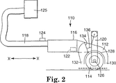
図2は、リベット及び/又は波状の曲線といった表面不規則部分を設計により有する基材(例えば、トラックトレーラ又はデリバリーバンのようなユーティリティービークル)のための表面アプリケータ110を示し、アプリケータ110は熱源112、及び、第一ハンドル118を有するフレーム116によって結合された表面順応性圧力源114を有する。場合により、しかし好ましくは、アプリケータ110は、アプリケータ110をガイドする第二ハンドル120、熱源112の温度を測定するための温度センサ122、センサ122により測定された温度を制御しそして場合により表示するための温度コントローラ124を有する。フレーム116は、アプリケータ110の他の要素のための強固でかつ軽量の支持体を提供するべきであり、そしてそれは軽量金属又は硬質ポリマーのような材料から構成されることができる。
【0037】
熱源112は、フィルムが圧力源114により不規則又は複合表面に対して押圧されるまで、フィルムを軟化点に維持するような温度を発生することができるどの熱源であってもよい。その温度で、フィルムは軟化され、そして回復する傾向を殆ど示さないか又は全く示さず、それにより、フィルムを不規則表面又は複合表面に順応して付着させる。好ましくは、温度は、軟化されるフィルムの組成により、約150℃〜約350℃の範囲である。このような熱源の制限しない例は、熱風を発生するヒートガン、赤外線を発生する石英ヒータ、プロパンなどを含むことができる。このような熱源112のための出力源は、フレーム116に接続されていても又はフレーム116から離れていてもよく、ファンもしくは圧縮空気源を伴う燃料加熱要素又は電気加熱要素のいずれかであることができる。好ましくは、熱源112は、温度センサ122及び温度コントローラ124を有する少なくとも300ワットの電気加熱要素である。図2から明らかなように、熱源112により加熱される空気の源は、フレーム116に接続されたリモートエアブロア125であることができる。
【0038】
アプリケータ110は、低い伝熱性を有する順応性表面を有する圧力源114を有する。一般に、圧力源114はフィルムを定位置にプレスするために使用される表面であり、基材表面の不規則性に適合すべきであり、そしてフィルムが基材表面と接触するまで熱源112からの熱を保持すべきである。図2の態様において、フレーム116に取り付けられた、軸126に対して回転するローラー114が使用される。順応性表面及び低伝熱性の両方を有する制限しない例は、天然もしくは合成ゴム、ウレタンポリマー、シリコーンポリマー(例えば、Roger800 Poron TMシリコーンフォーム、1/2インチ厚さ)、フルオロエラストマー、及び、特にこれらの材料の発泡体などを含む。
【0039】
アプリケータ110の有用性は、基材に付着されるフィルム上で熱源112及び圧力源114が交差するポイント付近の軸に沿ってフレーム116上に第二ハンドル120を配置することにより高められる。第一ハンドル118とともに第二ハンドル120を前方に配置することで、熱源112と圧力源114とが交差するポイントの跡を残し、基材に沿ったアプリケータ110の適用の軸X−Xを形成する。労働を節約するアプリケータ110の単一パス使用では、このX−X軸は、人がアプリケータ110をガイドする助けとなる。
【0040】
アプリケータ110は、デフレクタ128の周囲の熱をノズル130又はノズル132のいずれかに輸送するようになっている。熱の方向は、ノズル130又はノズル132のいずれかへの熱風の流れを妨害する可動性ウィングを有するバッフル134により分配される。軸X−Xの前方向又は後ろ方向に回転することができるハンドル120への連結部136によりバッフル134は制御される。このため、小さい動きでもって、アプリケータ110を使用している人はハンドル120を動かし、フィルムへ到達する熱の方向を制御することができる。本発明の特徴はフィルムを圧力で基材に付着させる前にフィルムを加熱することであるから、この方向制御によって、軸X−Xに沿って両方の方向でアプリケータ110を使用することが可能となる。
【0041】
図3は,図1に見られる態様とは別の態様を示す。この図において、アプリケータ310は、基材350の表面340にフィルム330を適用するための熱源312及び圧力源314を有する。熱源312は、赤外線のような放射線の形でフィルム330に熱を供給する。このように、図1及び2に示される態様に使用されるように、フィルムに熱を輸送するために対流は使用されない。
【0042】
図4は図1及び3に見られる態様とは別の態様を示す。この態様において、アプリケータ410は、熱源412及び圧力源414を有するが、熱源412は、基材450の表面440にフィルム430を適用する前に、圧力源414上で回転しているフィルム430に熱を向ける。この態様は、圧力源がフィルムを基材に輸送している間に、圧力源上でフィルムの加熱の位置が生じることができることを示している。
【0043】
図5は、画像グラフィック基材表面上の異なるタイプの表面不規則部分又は複合表面:基材の対向表面で強化材に表面を結合するために使用されるリベットについての態様を示す。リベットはトラックトレーラ又はデリバリーバンの上に多く存在し、そしてフィルムを確実に適用するのに非常に時間を要する。この態様において、アプリケータ510は熱源512及び圧力源514を有し、圧力源514は熱源512の周囲に環状になっている。環状圧力源514はリベットの隆起した複合曲面を収めるサイズである。源514はチャンネル、溝、くぼみ、その他の突起及びへこみのような他の不規則表面形状を収めるように変更されてもよい。熱源512は同心で環状圧力源514内にあるか又はずれており、リベットの隆起した複合曲面と接触しているフィルム又はリベット全体を包囲しているフィルム、或いは、その両方が圧力源514の適用と同時に加熱されうるようになっている。熱源512及び圧力源514の両方はハンドル518を有するフレーム516に取り付けられている。フレーム516は、また、リベットの周囲の基材の表面と熱源514の環が接触した後に、熱源から空気を逃がすことができる排気ポート520を有する。
【0044】
熱源512、圧力源514及びフレーム516のために使用される材料は、図2に見られる熱源112、圧力源114及びフレーム116に使用される材料と同一であることができる。場合により、アプリケータ510は、また、上記の図2に見られる態様について上記に記載したのと同じ目的で、図5に見られるような位置に温度センサ522及び温度コントローラゲージ524を有することができる。
【0045】
典型的な画像グラフィックフィルムの加熱及び冷却速度は数百℃/秒であるから、従来のアセンブリー技術を使用したときに、成形/適用が完了することができる前にフィルムが室温付近にまで冷えることが非常に頻繁にある。フィルムが適切に軟化されていないときに適用されたフィルムは接着結合が不良になることがある応力を示す。不良によりフィルムが表面から浮き上がり、外観不良及びフィルムの損失につながる。適用されているフィルムの融点に近くでの加圧適用を行なうと、浮き上がり不良が低減される。
【0046】
アプリケータ10、110、310、410又は510のいずれによっても、当業者がフィルムに損傷を与えることなく融点又は融点付近でフィルムを適用することができる。フィルムが応力下にある不規則もしくは複合表面位置で同時に交差している熱源及び圧力源を使用すると、意外にもフィルムの損傷が最小化される。フィルムが熱い間に、熱を散逸しないローラー14、114、314、414又は環状リング514を使用してフィルムを定位置に押圧する。熱いフィルムがレセプター表面と接触するときに、それは即座にクエンチされる。この方法は、低い性能又は剥離可能であると考えられるものを含む多くの接着剤により克服されうるレベルにフィルム内の残留応力を低減する。
【0047】
どの接着剤をコートしたフィルムも本発明のアプリケータから利益を受けることができる。このようなフィルムの制限しない例は、Minnesota Mining and Manufacturing Company(3M),St.Paul,MN,USAによりScotchcal(商標)、Controltac(商標)などで現在販売されているフィルムを含む。
【0048】
接着剤をコートしたフィルム、すなわち、Controltac(商標)180フィルムは、約200℃〜約400℃の空気温度で本発明のアプリケータを用いてうまく付着されることができるが、実際のフィルム温度はせいぜい170〜200℃に上げられることが判った。圧力源から時間的及び位置的に分離された従来の熱源を用いると、必要な温度を生じることができるが、リベットブラシの使用はフィルムを約100℃に冷却することを要求し、基材の表面不規則部分の周囲でフィルムを永久に変形するには不充分であることが判った。トラックトレーラの外側表面を擬似するために、多くのリベットを含む白色塗装された波状金属パネルに、PCT特許公開WO98/29516に開示された接着剤を有するControltac(商標)180フィルム(Minnesota Mining and Manufacturing Companyから市販)を適用した。フィルムライナーを除去し、そしてフィルムを波状体の上に横たえ、軽い圧力を加えて初期付着を提供した。その後、図2に見られる図に似たアプリケータを波状体の間の谷にロールダウンした。圧力源は軟質ポリウレタンフォームローラーを有し、種々の温度で熱を加えた。McMaster Carrから市販されているSteinelヒートガンに表示されている温度を記録した。その後、付着されているフィルムを有するパネルを6日間老化用オーブンに入れ、79℃に加熱した。その後、オーブンからパネルを取り出し、3週間放置し、リベット周囲からのフィルムの自然浮き上がり測定した。結果を下記の表1に示す。
【0049】
適用温度(℃) リベットでの平均浮き上がり(cm)
65 0.396
93 0.277
121 0.317
149 0.317
177 0.256
204 0.119
232 0.119
260 0.109
288 0.045
【0050】
これらの結果は、ビニルフィルムについて、200℃を超える熱空気温度は、リベット周囲でのフィルムの自然浮き上がりを有意に抑制することを示す。本発明の製品は、表面不規則部分又は複合曲面に順応して、基材に対するフィルムの耐久性付着を達成することができる、別個のヒートニュートラル圧力源とともにこのような熱に提供することができる。
【0051】
波状形状でかつリベット付けされた基材上にフィルムを付着させるために通常に要求される時間の80%までを節約でき、このようなフィルムを付着させる総コストを50%まで削減できることも判った。
【0052】
フィルム上の剥離可能な又は再配置可能な接着剤を使用すると、このようなフィルムを除去するコストも実質的に低減できる。剥離可能な又は再配置可能な接着剤を有するフィルムは、Minnesota Mining and Manufacturing Company,St.Paul,MN,USAからCommercial Graphic Divisionにより販売されるScotchcal(商標)シリーズ3500フィルムを含む。
【0053】
本発明の目的では、接着剤は、意図した基材に適用したときに、意図した寿命の最後に、場合により熱を用いて手で25フィート/時(7.62メートル/時)を超える速度で基材に対して損傷を与えることなく製品を除去することができるならば「剥離可能」であると考えられる。
【0054】
本発明のアプリケータ及び方法を用いて、全く新しいビジネス法を作り出すことができる。このビジネス法は、グラフィックマーキングフィルム上に画像を作製するために、その画像の所有者と契約することを含み、ここで、グラフィックマーキングフィルムの製造者が画像を印刷しそして本発明のアプリケータ及び方法を用いて基材上に画像グラフィックフィルムに作製する。または、フィルム製造者はアプリケータ及び方法の使用をサブコントラクトし、さらなる分配又は使用のために、離れた下請け業者が基材上にフィルムを作製することが可能になる。好ましくは、画像は複数の離れた場所に分配され、そして全ての場所で同一の技術を用いて印刷されそして作製され、全ての場所が本発明のアプリケータ及び方法により与えられる労働力節約から利益を享受できる。
【図面の簡単な説明】
【図1】本発明の物品の透視図である。
【図2】本発明の物品の第二の態様の透視図である。
【図3】本発明の物品の第三の態様の透視図である。
【図4】本発明の物品の他の態様の図である。
【図5】本発明の物品の他の態様の図である。[0001]
Field of Invention
The present invention relates to a method and product for reducing the effort of adhering an adhesive-coated film to the surface of a substrate, particularly a substrate having an uneven surface, and improving the quality of its application.
[0002]
Background of the Invention
Today, adhesive coated plastic films, particularly vinyl films with pressure sensitive or pressure activated adhesives, are affixed to various surfaces for various reasons such as advertising, decoration, protection, and the like. Many of these surfaces, like the side of a truck trailer, contain rivets and other protrusions or dents. When a film is applied to and adhered to such an uneven surface, the film is pulled to bring the adhesive into contact with the uneven surface. Residual stresses in the film at such uneven surface sites often exceed the retention of the adhesive, and as a result, the film will lift from the bonded surface, especially the rivet where the surface strengthens the sides of the track trailer Or it is remarkable when it is not flat like the circumference of a rib.
[0003]
Current methods of applying to uneven surfaces include applying a large portion of the film with a small plastic spatula leaving a small area around the protrusion or indentation. Completing this application involves treating the rivets to minimize lift by heating the film with a heat source, usually a hot air gun or torch, after the film has adhered to a non-planar surface. The film is usually heated while bridging the area around any type of surface irregularities that can be either protrusions or indentations. This film does not come into contact with customary tools. This is because the film is very soft and sometimes sticky. When touched, it usually takes damage. The heating rate is several hundred degrees per second because of the low film bulk and the high temperature of the heat source. Similar cooling rates are also used. When the film is pushed by a tool, usually a rib spatula or rivet rivet brush, it is only slightly above room temperature. This slows the crystallization time of the film and makes the film follow more, thus improving the film press without warming. Rivet brushes are usually stiff brushes with bristles about 2.54 cm in diameter and 1.25 cm in length attached to a short wooden handle. If the film is too soft due to heating, the film will be damaged when touched in a circular motion using a rivet brush. If the film is cooled too much, the stress will not be removed properly and will rise on average. In an attempt to relieve residual stress, the film is often heated after application, but the temperature at which the film is heated is limited by the thermal conductivity of the metal surface directly below the film. Therefore, it is very difficult for those skilled in the art to securely bond a film coated with an adhesive on an uneven surface by completely softening the film without damaging the structure of the film or its appearance. If there is damage, the film will weaken at that site, reducing the durability of the film. If there is an image graphic on the film, the image will be distorted or destroyed at the damaged site. If the image is damaged, even if the image is as large as the side wall of the truck trailer, it will stand out, adhere to the trailer owner, the supplier of the product shown on the side wall of the trailer, and the graphic film on the side of the trailer It is unsatisfactory for a processor who has spent considerable effort to do.
[0004]
If the film lifts due to residual stress, the film will tear, peel or be damaged, otherwise it cannot meet the demand for a surface that should have a paint-like appearance.
[0005]
Summary of the Invention
The present invention provides a method of adhering an adhesive coated film to a substrate by heating the film to its softening point and applying the softened film to the substrate by pressure using a heat neutral pressure source. .
[0006]
The invention also provides a product that softens the film and adheres the film to the surface of the substrate, which includes a heat source and a heat neutral pressure source, the heat source and the heat neutral pressure source being in contact with the film. Heat and pressure are applied at the intersections on the surface.
[0007]
Detailed Description of the Invention
The present invention recognizes the problems associated with the adhesion of plastic films, particularly vinyl films, coated with adhesive applied to flat and uneven surfaces to give improved appearance, durability, etc. . For the purposes of the present invention, a “non-planar surface” is the completeness of an adhesive-coated film to that surface due to the presence of protrusions, depressions or other such non-planar geometric shapes. A surface that cannot be matched. Since the film is usually stretched to fit a particularly uneven surface during application, the pressure sensitive adhesive must secure the film to the surface under various stresses. So far, only films with high performance adhesives have been used in such applications with good results. The most common troublesome surfaces include corrugated track sides with rivets, curved vehicle panels, containers and vehicle grooves.
[0008]
Surprisingly, the present invention provides excellent adhesion of thermoplastic films to highly uneven surfaces or highly textured surfaces such as concrete, cement blocks, stucco, bricks, fabric surfaces, carpeted surfaces, etc. Provide sex. Films applied to such surfaces without using the method of the present invention have a significant number of portions that are not in contact with the surface of the substrate, particularly at the edges of the film. Films applied to such surfaces using the method of the present invention have the appearance of being applied to the surface due to the close fit of the film to the substrate. In addition, the edges of the film advantageously fit closely to the substrate, thus reducing the urge to remove the passer's film.
[0009]
For the purposes of the present invention, a “highly textured surface” is a surface that contacts less than 90% of the surface area of a 4 mil film applied to a surface with a 4 kg roll load. It is a sufficiently uneven surface.
[0010]
Anyone who has attempted to put up wallpaper will readily see that applying a film coated with an adhesive on a vertical surface is very cumbersome and time consuming. Application of such materials to troublesome surfaces such as cargo trailers is quite difficult. At least, typically, the walls are flat and do not include complex geometric or non-planar surfaces. Typically, the size of a piece of wallpaper is about 70 cm wide and about 2.5 m long. In the technical field related to the present invention, the application of adhesive-coated film to the vertical surface of a cargo trailer is performed in a very wide variety of situations, and the substrate is often filled with geometric irregularities. The film pieces have a width of about 120 cm and a length of about 3 m. This assembly requires very skilled personnel, and such assembly takes a very long time and takes about 22 hours per cargo trailer.
[0011]
The traditional method is to first pierce the film so that air can escape, apply heat to the film to make the film somewhat soft, and finally apply pressure using a brush, circular motion and sufficient pressure Required the individual treatment of each rivet area, including pressing the film against the substrate using. Because of the pressure and movement required for this application, the film could not be made very soft when brushed into the proper condition. The film had to be allowed to cool to a temperature at which the structural integrity of the film could withstand the force applied to the film by the brush. It is not uncommon for applications in each trailer using the prior art to show film damage or poor film placement on the rivet in at least a few rivets. The present invention, in contrast, provides a single stroke of film to the substrate at each rivet without worrying about tearing or otherwise damaging the film through the application of force by brushing the rivets. Enable single stroke application. This difference in application technology can reduce application time by about 50% when applying film to cargo trailers related to rivet finishing.
[0012]
It is practically impossible to apply the film using conventional tools without sufficiently softening the film so that all residual stresses are removed or even damaging the film. Furthermore, the lack of control of the heating process and the very rapid cooling of the film after heating usually yields inconsistent results even if performed by a skilled applicator using high performance adhesives.
[0013]
The use of a film with a removable adhesive is highly desirable in the short term advertising industry, i.e. a display of less than about 12 months. Films with removable adhesive are mainly used on flat surfaces. This is because the adhesive does not sufficiently withstand the residual stress remaining after application to an uneven surface using conventional techniques. It requires significantly more heat to relax the film well than can be applied using only standard squeegees and rivet brushes.
[0014]
For the purposes of the present invention, a “heat neutral pressure source” is a film that does not adhere to a heat neutral pressure source during application to a surface according to the method of the present invention when the film is substantially melted. Pressure source having heat transfer characteristics and surface characteristics when in contact with such a film.
[0015]
Regarding the heat transfer characteristics, the configuration of the film contact portion of the heat neutral pressure source is one that does not conduct much heat to or from the surface of the film when the film is applied to the surface of the substrate under pressure. . In other words, the configuration has low thermal conductivity, but can withstand high temperatures. Preferably, the pressure source is 1.8 BTU / hr-in-ft as measured by ASTM C-518.2It has a thermal conductivity of less than -F °.
[0016]
With respect to the surface characteristics of the heat neutral pressure source, the film contact of the device should not cause the soft or molten film to be distorted or attached to the film so that it may tear or otherwise damage the film. Have a different shape. Thus, for example, cotton is a low thermal conductivity material, but cotton gloves would be unsuitable for use as a heat neutral pressure source for certain film materials. Because there are fibers and other such irregularities on the surface that leave gaps in the flow of very soft or melted film in it, and adhere to many very soft films. is there. Thus, the surface properties of cotton gloves can lead to a collapse of the film appearance when attempting to carry out the method of the present invention.
[0017]
The suitability of any particular material for use as a heat neutral pressure source in relation to any particular film is a non-planar surface coated with an adhesive coated film suitable for application to the intended substrate ( (E.g. the rivet part of the cargo trailer wall), heating the non-contact part of the film to approximately its melting point, and immediately using the material to be tested, essentially vertical (no rotational force applied) Quickly and routinely determined by pressing the film against the substrate. If the film sticks to the material to be tested, or if it is damaged by the material to be tested, the material is not suitable for use as a heat neutral pressure source.
[0018]
Preferably, the pressure source is compressible so that the film to be adhered to the substrate is in sufficient contact and adhesion. Thus, if the intended substrate includes a rivet that protrudes from the surface of the substrate, the non-compressible pressure source will not fit around the protruding rivet, resulting in film contact at the root of the rivet There is a part that is not done or “like a tent”. Preferred pressure sources allow sufficient conformation or compliance of the pressure source around any surface irregularities encountered in the intended application. The material preferably has a Poisson's ratio of less than 1, more preferably a Poisson's ratio of less than 0.9.
[0019]
Preferably, the pressure source is a foam material. Such materials, when properly selected, provide a high degree of compatibility and may have very low thermal conductivity. More preferably, the pressure source is an open cell foam material. Most preferably, the pressure source has a uniform surface structure so that when the pressure source is placed on the molten film material, the film does not exhibit a visible structure imprinted by the pressure source. A particularly preferred pressure source of the present invention is a handheld dauber-type device that can apply local pressure around specific irregularities of the substrate surface. Preferably, the surface area of the applicator is somewhat larger than the area of rivets normally found on trucks. Accordingly, a preferred pressure application device has a pressure surface with a diameter of about 7 cm. Instead, the heat neutral pressure source is a roller that is much like a paint roller. The preferred width of the roller depends on its application. For applying the film to a corrugated surface or a surface having rivets, a roller width of 2 to 15 cm is generally preferred. Accordingly, the heat neutral pressure source is preferably designed to provide a force that is essentially normal to the substrate with little or no lateral force applied to the film during application.
[0020]
Most preferably, the pressure source is an open cell silicone material.
In the method of the invention, the film to be applied to the substrate is heated to the softening point, i.e. highly flexible and soft compared to the behavior of the film at room temperature. More preferably, the film is heated to approximately its softening point, just below the temperature at which the film may change color or develop pores in the film.
[0021]
In one aspect of the present invention, a method of adhering an adhesive-coated film to a substrate comprises heating the film to the softening point of the film and applying a pressure using a heat neutral pressure source to form a soft film. Is applied to the substrate. Depending on the case, the entire film can be heated and applied simultaneously. Alternatively, without heating, the film can be applied to an uneven surface to maximize contact of the film with the substrate. This first stage of application leaves a portion of the film that is not actually in contact with the substrate, but that portion exists in a “tent-like” state between the portions in contact with the adhesive. . The portion of the film that is not in contact with the substrate is then heated to the softening point of the film and applied to the substrate with pressure using a heat neutral pressure source. Thus, the heat neutral pressure source is used to actually move the soft film into contact with the substrate. Surprisingly, because of the thermal conductivity and surface properties of this pressure source, the film fits the surface well without damaging the film.
[0022]
Preferably, the application of heat and pressure as described above is performed using a heat source and a separate pressure source. This can be a system operated by two people, one person operating the heat source and the other person operating the pressure source according to it quickly. More preferably, one person can also perform the method by using a handheld heat source (with one hand, like a hair dryer) and using a handheld pressure source (like an applicator) with the other hand . This method can thus continue along a row of rivets or the like in a rhythmic motion in which heat is first applied with one hand and then immediately applied with the other hand.
[0023]
In the method of the present invention, it is often desirable to first provide pores in the film located in the immediate vicinity of the surface irregularities in the part where the film is not in contact with the substrate before heating the film. Such pores provide an escape path for air trapped between the film and the substrate. Preferably, air is allowed to escape while the pressure source applies pressure to the film so that applying the pressure by the pressure source does not allow air to escape through the pores. Most preferably, the foam material is an open cell foam material that allows easy movement of air. Preferably, the foam of the pressure source foam material is not so large as to engrave the bubble pattern into the softened film. That is, the pressure source preferably has bubbles having a diameter of about 0.5 mm or less, more preferably 0.2 mm or less.
[0024]
Particularly preferred pressure sources of the present invention comprise a low energy surface that contacts the softened film during film application. Such low energy surfaces include silicone materials or silicone coating materials. Further such low energy surfaces include materials or coatings comprising perfluorinated materials or other such materials known in the low adhesion backsize art.
[0025]
In another aspect of the invention, a heat source made to apply heat to the film, and a pressure source that is heat neutral, a pressure that can be used in conjunction with the heat source for application of the film to the intended substrate. A kit comprising a source is provided. Another aspect of the present invention is to provide a unitary article for applying both heat and pressure to an adhesive coated film.
[0026]
Another aspect of the present invention is a method of adhering an adhesive coated film to a substrate having a surface, wherein the article is applied to the surface to apply heat and pressure to the substrate. The step of adhering. However, the pressure source of the article is heat neutral.
[0027]
Another aspect of the present invention is a method for reducing labor in bonding an adhesive-coated film to a substrate having a surface, wherein (a) the applicator of the present invention and the method of the present invention are already used. Distributing the film to the taught population; (b) optionally causing the population to print an image on the film; and (c) allowing the population to use the application kit or applicator and the method to form a substrate. A method comprising adhering a film to a film.
[0028]
One feature of the present invention is that it is a time-spatial scheme that provides thermal and mechanical modification of the film at irregularities or complex shapes on the surface, and that the pressure source is heat neutral, on the substrate. It is an article that applies both heat and pressure to the uneven surface of the surface.
[0029]
Another feature of the present invention is the manner in which very little stress on the film bonded to the flat surface is removed prior to bonding, and at some point on the large flat surface during bonding, And an article that applies pressure.
[0030]
The present invention reduces labor with the importance that it can substantially reduce the overall overall cost for the purpose of applying image graphic film to large vertical substrates with complex shapes or uneven surfaces. give. Even if the cost of the film is constant, this reduction in labor reduces the overall cost by as much as 50% for applying unprinted film to a riveted corrugated trailer. In addition, the present invention allows the film to adhere to trailers and other difficult environment areas with relatively low stress and / or film memory, thus making the adhesives that are not very aggressive to those difficulties. Can be used in any environment. This is a very important advantage. This is because a less invasive adhesive can be used, so that the end user can more easily remove the film of the present invention. The cost of removing such a film will decrease significantly by as much as 50%.
[0031]
Preferably, the applicator and method of the present invention is used with little training so that less skilled employees and consumers can operate the applicator to obtain a film that adheres properly to the substrate. it can.
[0032]
It is envisioned that the present invention significantly expands the choice of adhesives for applying a film to a surface, including any of pressure sensitive adhesives, pressure activated adhesives and heat activated adhesives.
[0033]
Furthermore, it is believed that a fairly wide selection of films has become possible for use in graphic applications on various substrates, such as elastic films that are not normally available for graphic applications. Such films, which usually show considerable memory when applied to an uneven substrate, can be thermally relaxed during application to remove residual stress. This allows many different types of elastic films, such as unstretched polyolefin films, polyurethane films, ionomer resin films, acrylic films, fluoroelastomer films, etc. that could not otherwise be used as graphic marking films on uneven surfaces. Can be used.
[0034]
Furthermore, the present invention allows the use of hard films that exhibit good handleability and durability. This is because such films can be softened upon application to fit uneven or complex curved surfaces. Examples of the hard film are a poly (meth) acrylate film, a hard polyvinyl chloride sheet, a polyester film, a stretched polyolefin film, a polycarbonate sheet, and a styrene sheet.
[0035]
FIG. 1 is a view showing a product of the present invention. The
[0036]
FIG. 2 shows a
[0037]
The
[0038]
[0039]
The usefulness of the
[0040]
[0041]
FIG. 3 shows an alternative embodiment to that shown in FIG. In this view,
[0042]
FIG. 4 shows an alternative embodiment to that seen in FIGS. In this aspect, the
[0043]
FIG. 5 shows aspects for different types of surface irregularities or composite surfaces on the image graphic substrate surface: rivets used to bond the surface to the reinforcement at the opposing surface of the substrate. Rivets are often present on track trailers or delivery vans and take a very long time to reliably apply the film. In this embodiment, the
[0044]
The materials used for
[0045]
Typical image graphic film heating and cooling rates are several hundred degrees Celsius / second, so when using conventional assembly techniques, the film cools to near room temperature before molding / application can be completed. There are very often. Films applied when the film is not properly softened exhibit stresses that can result in poor adhesive bonding. Defects raise the film from the surface, leading to poor appearance and film loss. When pressure is applied close to the melting point of the applied film, the floating defect is reduced.
[0046]
Any of the
[0047]
Any adhesive-coated film can benefit from the applicator of the present invention. Non-limiting examples of such films are described in Minnesota Mining and Manufacturing Company (3M), St. Includes films currently sold by Scotchcal ™, Controlac ™, etc. by Paul, MN, USA.
[0048]
Although the adhesive coated film, ie, Controlac ™ 180 film, can be successfully applied using the applicator of the present invention at an air temperature of about 200 ° C. to about 400 ° C., the actual film temperature is It was found that the temperature could be raised to 170-200 ° C at best. Using a conventional heat source that is separated in time and position from the pressure source can produce the required temperature, but the use of a rivet brush requires the film to be cooled to about 100 ° C. It has been found that it is insufficient to permanently deform the film around the irregular surface. In order to simulate the outer surface of a track trailer, a white painted corrugated metal panel containing many rivets is applied to a Controlac ™ 180 film (Minnesota Mining and Manufacturing) with adhesive disclosed in PCT patent publication WO 98/29516. (Commercially available from Company). The film liner was removed and the film was laid over the corrugations and light pressure was applied to provide initial deposition. Thereafter, an applicator similar to the view seen in FIG. 2 was rolled down into the valleys between the corrugations. The pressure source had a flexible polyurethane foam roller and applied heat at various temperatures. The temperature displayed on a Steinel heat gun commercially available from McMaster Carr was recorded. The panel with the attached film was then placed in an aging oven for 6 days and heated to 79 ° C. Thereafter, the panel was taken out of the oven and allowed to stand for 3 weeks, and the natural lifting of the film around the rivet was measured. The results are shown in Table 1 below.
[0049]
Application temperature (℃) Average lift with rivets (cm)
65 0.396
93 0.277
121 0.317
149 0.317
177 0.256
204 0.119
232 0.119
260 0.109
288 0.045
[0050]
These results show that for vinyl films, hot air temperatures above 200 ° C. significantly suppress the natural lift of the film around the rivets. The product of the present invention can provide such heat with a separate heat neutral pressure source that can accommodate surface irregularities or complex curved surfaces to achieve durable adhesion of the film to the substrate. .
[0051]
It has also been found that up to 80% of the time normally required to deposit a film on a wavy and riveted substrate can be saved, and the total cost of depositing such a film can be reduced to 50%. .
[0052]
Using a peelable or repositionable adhesive on the film can also substantially reduce the cost of removing such a film. Films with peelable or repositionable adhesives are described in Minnesota Mining and Manufacturing Company, St. Includes Scotchcal ™ series 3500 film sold by the Commercial Graphic Division from Paul, MN, USA.
[0053]
For purposes of the present invention, the adhesive, when applied to the intended substrate, at speeds exceeding 25 feet / hour (7.62 meters / hour) by hand, possibly with heat, at the end of the intended life. If the product can be removed without damaging the substrate, it is considered “peelable”.
[0054]
The applicator and method of the present invention can be used to create entirely new business methods. The business method involves contracting with the owner of the image to produce an image on the graphic marking film, where the graphic marking film manufacturer prints the image and the applicator of the present invention and The method is used to produce an image graphic film on a substrate. Alternatively, the film manufacturer subcontracts the use of the applicator and method, allowing a remote subcontractor to produce the film on the substrate for further distribution or use. Preferably, the images are distributed to multiple remote locations and printed and created using the same technology at all locations, all locations benefiting from the labor savings afforded by the applicator and method of the present invention. Can be enjoyed.
[Brief description of the drawings]
FIG. 1 is a perspective view of an article of the present invention.
FIG. 2 is a perspective view of a second embodiment of the article of the present invention.
FIG. 3 is a perspective view of a third embodiment of the article of the present invention.
FIG. 4 is a diagram of another embodiment of the article of the present invention.
FIG. 5 is a diagram of another embodiment of the article of the present invention.
Claims (10)
a)このフィルムをその軟化点まで加熱すること、
b)ヒートニュートラル圧力源を用いた圧力により、軟化したフィルムを基材に貼り付けること
を含む方法。A method of adhering an adhesive-coated film to a substrate having a surface,
a) heating this film to its softening point;
b) A method comprising applying a softened film to a substrate by pressure using a heat neutral pressure source.
b)基材に接触していないフィルムの部位を、そのフィルムの軟化点まで加熱すること、
c)ヒートニュートラル圧力源を用いた圧力により、軟化したフィルムを基材に貼り付けること
を特徴とする、請求項2記載の方法。a) affixing the film to the substrate with maximum film contact to the substrate without heating,
b) heating the part of the film not in contact with the substrate to the softening point of the film;
3. The method according to claim 2, wherein the softened film is attached to the substrate by pressure using a heat neutral pressure source.
Applications Claiming Priority (5)
| Application Number | Priority Date | Filing Date | Title |
|---|---|---|---|
| US23680699A | 1999-01-25 | 1999-01-25 | |
| US09/236,806 | 1999-01-25 | ||
| US47964800A | 2000-01-07 | 2000-01-07 | |
| US09/479,648 | 2000-01-07 | ||
| PCT/US2000/001676 WO2000043220A1 (en) | 1999-01-25 | 2000-01-25 | Method of applying adhesive coated film |
Publications (3)
| Publication Number | Publication Date |
|---|---|
| JP2002535170A JP2002535170A (en) | 2002-10-22 |
| JP2002535170A5 JP2002535170A5 (en) | 2006-08-03 |
| JP4373014B2 true JP4373014B2 (en) | 2009-11-25 |
Family
ID=26930126
Family Applications (1)
| Application Number | Title | Priority Date | Filing Date |
|---|---|---|---|
| JP2000594658A Expired - Fee Related JP4373014B2 (en) | 1999-01-25 | 2000-01-25 | Method for applying adhesive coated film |
Country Status (10)
| Country | Link |
|---|---|
| US (3) | US8608897B2 (en) |
| EP (1) | EP1147019B1 (en) |
| JP (1) | JP4373014B2 (en) |
| KR (1) | KR100594789B1 (en) |
| CN (1) | CN1153684C (en) |
| AU (1) | AU2857400A (en) |
| BR (1) | BR0007687A (en) |
| CA (1) | CA2360037C (en) |
| DE (1) | DE60004966T2 (en) |
| WO (1) | WO2000043220A1 (en) |
Families Citing this family (27)
| Publication number | Priority date | Publication date | Assignee | Title |
|---|---|---|---|---|
| US9855732B2 (en) | 1999-01-25 | 2018-01-02 | 3M Innovative Properties Company | Method of applying adhesive coated film |
| BR0007687A (en) | 1999-01-25 | 2002-01-29 | 3M Innovative Properties Co | Process of adhesion of an adhesive-coated film to a substrate having a surface, article to soften a film and adhere the film to a surface of a substrate, process to save labor of adhesion of an adhesive-coated film to a substrate having a surface , e, kit for applying films to a substrate |
| US7413626B2 (en) | 2001-01-12 | 2008-08-19 | 3M Innovative Properties Company | Adhesive film removal method and apparatus |
| US6706131B2 (en) | 2000-05-23 | 2004-03-16 | 3M Innovative Properties Company | Film lamination and removal system and methods of use |
| CA2471767A1 (en) * | 2002-01-08 | 2003-07-24 | 3M Innovative Properties Company | Method of conforming a film to a surface |
| US6872268B2 (en) | 2002-06-11 | 2005-03-29 | 3M Innovative Properties Company | Method of conforming an adherent film to a substrate by application of vacuum |
| US8778122B2 (en) | 2006-06-29 | 2014-07-15 | 3M Innovative Properties Company | Adhering graphic films on irregular substrates |
| US20080003406A1 (en) | 2006-06-29 | 2008-01-03 | 3M Innovative Properties Company | Displaying Printed Images on Irregular Substrates |
| DE102009044082A1 (en) * | 2009-09-23 | 2011-04-21 | Rinn Beton- Und Naturstein Gmbh & Co. Kg | Tile or road stone, has impression i.e. digital impression, arranged on upper side and composed of UV- hardening paint and dual lacquer coat arranged on impression, where tile or road stone is made of concrete natural stone |
| WO2011050254A1 (en) | 2009-10-24 | 2011-04-28 | 3M Innovative Properties Company | Light source and display system incorporating same |
| WO2011071728A1 (en) | 2009-12-08 | 2011-06-16 | 3M Innovative Properties Company | Optical constructions incorporating a light guide and low refrative index films |
| KR101796806B1 (en) | 2010-04-12 | 2017-11-10 | 쓰리엠 이노베이티브 프로퍼티즈 컴파니 | Optical stack and lightguides |
| US9415540B1 (en) | 2011-04-04 | 2016-08-16 | Geek Wraps, Inc. | Roller tool for use in applying adhesive vinyl wraps to surfaces |
| WO2013052319A1 (en) | 2011-10-05 | 2013-04-11 | 3M Innovative Properties Company | Microstructured transfer tapes |
| US9189982B1 (en) | 2011-10-25 | 2015-11-17 | Gregory Michael Stone | System for installing film containing a message on a vehicle |
| DE102013222636A1 (en) * | 2013-11-07 | 2015-05-07 | Homag Holzbearbeitungssysteme Gmbh | Method for applying a coating to workpieces and apparatus for coating workpieces |
| KR101688114B1 (en) * | 2014-03-24 | 2016-12-22 | 주식회사 아바코 | Apparatus and method of bonding a film |
| EP3177445A4 (en) * | 2014-08-04 | 2018-03-07 | 3M Innovative Properties Company | Finishing system for 3d printed components |
| DE102014018933A1 (en) * | 2014-12-22 | 2016-06-23 | Airbus Defence and Space GmbH | Device for consolidating a preform |
| EP3357253B1 (en) * | 2015-10-02 | 2021-12-22 | Twitter, Inc. | Gapless video looping |
| CN106218309A (en) * | 2016-08-30 | 2016-12-14 | 荆门千年健医疗保健科技有限公司 | A kind of special purpose device for pasting seamless wall cloth |
| EP3363617A1 (en) * | 2017-02-16 | 2018-08-22 | 3M Innovative Properties Company | An apparatus for applying a film |
| US10994492B2 (en) * | 2017-12-12 | 2021-05-04 | Kenneth A. Fullick | Apparatus and method of welding fabric material to a frame including for removable use in a door or window opening |
| CN108058398B (en) * | 2017-12-13 | 2023-11-14 | 新乐华宝塑料制品有限公司 | Full-automatic shower curtain machine |
| CN109017123A (en) * | 2018-09-29 | 2018-12-18 | 侯马市迪科特电子科技有限公司 | One kind being used for wallpaper laminating apparatus |
| CN109504293A (en) * | 2018-10-29 | 2019-03-22 | 昆山国显光电有限公司 | Optical cement applying method and its laminating apparatus |
| CN111370360A (en) * | 2018-12-26 | 2020-07-03 | 中芯集成电路(宁波)有限公司 | Substrate film pasting method and packaging method |
Family Cites Families (105)
| Publication number | Priority date | Publication date | Assignee | Title |
|---|---|---|---|---|
| US754403A (en) * | 1901-06-27 | 1904-03-08 | Walter H Coe | Gilder's tool. |
| GB135928A (en) | 1918-12-03 | 1919-12-03 | Joseph Christopher Wells | Improvements in Apparatus for use as an Indicator of the Movements of Vehicles and for the Regulation of Traffic generally. |
| US1672093A (en) * | 1928-01-31 | 1928-06-05 | Helena S Sadtler | Art of decorating the surfaces of various objects |
| US1895045A (en) * | 1931-07-17 | 1933-01-24 | James L Moore | Method and means for marking surfaces |
| US1887847A (en) | 1932-02-25 | 1932-11-15 | Abram S Peiper | Method of permanently securing linoleum to normally damp concrete surfaces |
| US2123415A (en) * | 1937-07-28 | 1938-07-12 | A J Allgoewer | Taping instrument |
| US2372737A (en) * | 1943-04-16 | 1945-04-03 | Udylite Corp | Torch for welding thermoplastic material |
| US2714559A (en) * | 1950-03-27 | 1955-08-02 | Us Plywood Corp | Coated plastic sheet and method of making same |
| US3047050A (en) | 1959-06-19 | 1962-07-31 | Sourber Earl Jacob | Hot air welding apparatus |
| US3214502A (en) | 1960-08-08 | 1965-10-26 | Kendall & Co | Method and apparatus for making adhesive tapes |
| US3300355A (en) * | 1963-06-20 | 1967-01-24 | William E Adams | Method of making irregularly shaped hollow plastic bodies |
| US3466212A (en) | 1965-03-24 | 1969-09-09 | Mobil Oil Corp | Quilted film process |
| US4117181A (en) * | 1972-04-20 | 1978-09-26 | Dai Nippon Printing Co., Ltd. | Decorative laminated structures and method of making the same |
| US3853669A (en) * | 1972-08-28 | 1974-12-10 | P Werstlein | Welding tip for plastic welding gun |
| US3861988A (en) * | 1973-01-22 | 1975-01-21 | Samuel L Preisler | Pressure sensitive rolled sheeting applicator and dispenser |
| DK143357A (en) * | 1973-09-14 | 1900-01-01 | ||
| AR204760A1 (en) * | 1974-05-29 | 1976-02-27 | Schlegel Engineering | PROCEDURE FOR THE CONTINUOUS WELDING BY OVERLAPPING OF THERMOPLASTIC SHEETS OR PLATES AND DEVICE TO CARRY IT OUT |
| US4181752A (en) * | 1974-09-03 | 1980-01-01 | Minnesota Mining And Manufacturing Company | Acrylic-type pressure sensitive adhesives by means of ultraviolet radiation curing |
| US4126727A (en) | 1976-06-16 | 1978-11-21 | Congoleum Corporation | Resinous polymer sheet materials having selective, decorative effects |
| US4261783A (en) * | 1977-01-26 | 1981-04-14 | Monarch Marking Systems, Inc. | Label printing and applying apparatus |
| GB2030991B (en) | 1977-02-09 | 1982-11-24 | Nitto Electric Ind Co | Heat activatable pressuresensitive adhesive tape of sheet |
| US4204904A (en) * | 1977-10-17 | 1980-05-27 | Tabor Donald R | Roofing material handling and sealing machine |
| JPS555838A (en) | 1978-06-30 | 1980-01-17 | Asahi Glass Co Ltd | Method and device for plastic welding adhesion |
| US4212691A (en) | 1978-11-21 | 1980-07-15 | Congoleum Corporation | Methods and apparatus for making decorative inlaid types of resilient sheet materials and the like |
| US4244069A (en) * | 1979-05-29 | 1981-01-13 | Xerox Corporation | Method and apparatus for binding sheets |
| JPS6059876B2 (en) | 1979-09-28 | 1985-12-27 | 大日本印刷株式会社 | Cosmetic method for base material with unevenness |
| US4358495A (en) * | 1981-04-06 | 1982-11-09 | Parker Robert F | Drywall patch kit |
| JPS5817129A (en) | 1981-07-23 | 1983-02-01 | Shin Etsu Polymer Co Ltd | Foamed roller |
| JPS5845020A (en) * | 1981-09-11 | 1983-03-16 | Toshiba Mach Co Ltd | Pressing roll apparatus for automatically sticking tape |
| US4994514A (en) * | 1982-07-16 | 1991-02-19 | Phillips Petroleum Company | Encapsulation of electronic components with poly(arylene sulfide) containing mercaptosilane |
| CA1175330A (en) | 1982-09-01 | 1984-10-02 | David Bray | Method of manufacturing adhesive tape |
| US4511425A (en) * | 1983-06-13 | 1985-04-16 | Dennison Manufacturing Company | Heated pad decorator |
| IT1181914B (en) | 1984-01-11 | 1987-09-30 | Schaeffler Waelzlager Kg | INTERNAL RING FOR A TILTING ROTISM |
| DE3519064A1 (en) * | 1985-05-28 | 1986-12-04 | Avery International Corp., Wilmington, Del. | MULTILAYER, SELF-ADHESIVE AND DRAWN PROTECTIVE FILM, IN PARTICULAR FOR MOTOR VEHICLES |
| US4801586A (en) | 1986-04-23 | 1989-01-31 | Nelson Research & Development Co. | Penetration enhancers for transdermal delivery of systemic agents |
| US4867816A (en) * | 1986-06-06 | 1989-09-19 | Suiter James R | Bowling lane refinishing method |
| US4944514A (en) | 1986-06-06 | 1990-07-31 | Suitco Surface, Inc. | Floor finishing material and method |
| US4737213A (en) | 1986-09-03 | 1988-04-12 | Uniroyal Chemical Company, Inc. | Method for heat sealing thermoplastic membranes |
| WO1988002604A1 (en) | 1986-10-20 | 1988-04-21 | Bartasis James E | Protective garment material and construction |
| DE3732157A1 (en) | 1987-09-24 | 1989-05-18 | Thomas Hebel | Edge band adhesive-bonding device |
| US5010672A (en) * | 1988-02-29 | 1991-04-30 | Coleman Kelly R | Laminated sign |
| US4806194A (en) | 1988-03-07 | 1989-02-21 | Wald Richard D | Roofing paper applicator |
| JPH02261835A (en) * | 1989-03-31 | 1990-10-24 | Shin Etsu Chem Co Ltd | Foamable silicone rubber composition |
| DE69021267T2 (en) | 1989-05-11 | 1995-12-21 | Nippon Catalytic Chem Ind | Process for purifying a gas using an electrically heated MnO2 catalyst. |
| US5268215A (en) * | 1989-08-31 | 1993-12-07 | Eastman Kodak Company | Basecoat-clearcoat film |
| US5034077A (en) * | 1989-09-05 | 1991-07-23 | Jack Pata | Method for thermoforming and bonding a paint-coated polymeric film to a substrate |
| AU7110191A (en) | 1990-02-12 | 1991-08-15 | Neil Ross Galloway | Tlb process |
| US5306382A (en) | 1990-11-06 | 1994-04-26 | Avery-Dennison Corporation | Label dispenser conversion kit |
| JP2608343B2 (en) | 1990-11-27 | 1997-05-07 | 日東電工株式会社 | Heat-foaming double-sided adhesive sheet |
| US5248355A (en) | 1990-12-20 | 1993-09-28 | Owens-Illinois Plastic Products Inc. | Apparatus for applying heat sensitive labels and pressure sensitive labels |
| US5261996A (en) * | 1991-01-25 | 1993-11-16 | Minnesota Mining And Manufacturing Company | Guiding system for a vacuum wheel applicator |
| DE4105524A1 (en) | 1991-02-22 | 1992-08-27 | Kronseder Maschf Krones | METHOD AND DEVICE FOR APPLYING LABELS TO CONTAINERS |
| US5225260A (en) * | 1991-03-28 | 1993-07-06 | Brady Coated Products Co. | Subsurface printable laminate with carrier and application tape |
| US5246757A (en) | 1992-04-28 | 1993-09-21 | Minnesota Mining And Manufacturing Company | Architectural signs with raised graphics |
| EP0583940B1 (en) * | 1992-08-14 | 1997-04-23 | Toyo Ink Manufacturing Co., Ltd. | Method of thermal transfer recording |
| US5284689A (en) * | 1992-09-14 | 1994-02-08 | The Standard Register Company | Product label assembly |
| DE4232697A1 (en) | 1992-09-30 | 1994-03-31 | Schmidt Josef | Film applicator for profiled sections - has guide rollers in groups on supports which are adjustable perpendicular to the profile direction. |
| US5221408A (en) | 1992-11-13 | 1993-06-22 | Minnesota Mining And Manufacturing Company | Applicator for applying a label having a heat activated adhesive to an object having an elevated temperature |
| AU5881494A (en) | 1993-01-09 | 1994-08-15 | Gunter Tesch | Wall or furniture lining, in particular wallpaper |
| JPH071590A (en) * | 1993-05-07 | 1995-01-06 | Minnesota Mining & Mfg Co <3M> | Equipment and method to affix film on article |
| ATE184182T1 (en) | 1993-06-28 | 1999-09-15 | Procter & Gamble | METHOD AND DEVICE FOR ATTACHING CLOSURE ELEMENTS TO A DISPOSABLE DIAPER OF DIFFERENT DENSITY |
| US5445704A (en) * | 1994-01-18 | 1995-08-29 | Dizon; Cipriano | Wallpaper applicator |
| TW305870B (en) | 1994-04-28 | 1997-05-21 | Minnesota Mining & Mfg | |
| GB2289433B (en) | 1994-05-18 | 1996-12-04 | Rockwool Ltd | Damp-proof course |
| KR100354945B1 (en) | 1994-06-22 | 2003-03-15 | 다이니폰 인사츠 가부시키가이샤 | Decoration |
| JPH08118575A (en) | 1994-10-25 | 1996-05-14 | Sekisui Chem Co Ltd | Laminated sheet for coating and manufacture thereof |
| US5976690A (en) | 1995-05-18 | 1999-11-02 | 3M Innovative Properties Company | Opaque adhesives and method therefor |
| US5824638A (en) | 1995-05-22 | 1998-10-20 | Shire Laboratories, Inc. | Oral insulin delivery |
| US5693141A (en) * | 1995-07-21 | 1997-12-02 | Tramont; Thomas J. | Special effect paint roller |
| US5814184A (en) * | 1995-10-25 | 1998-09-29 | Denkins; Jeffrey L. | Hand operated mudless drywall tape applicator |
| JP2962404B2 (en) * | 1996-01-25 | 1999-10-12 | 日東電工株式会社 | Automatic sealing tape application device |
| DE69703536T2 (en) * | 1996-02-26 | 2001-06-28 | Minnesota Mining & Mfg | Graphic marking film containing pressure sensitive adhesive |
| US5874158A (en) | 1996-03-11 | 1999-02-23 | Minnesota Mining And Manufacturing Company | Heat activated translucent marking films |
| US6664359B1 (en) | 1996-04-25 | 2003-12-16 | 3M Innovative Properties Company | Tackified polydiorganosiloxane polyurea segmented copolymers and a process for making same |
| US5944935A (en) | 1996-07-24 | 1999-08-31 | Zukas; Florian J. | Preparation of adhesively bonded sandwich structures |
| US6270871B1 (en) * | 1996-09-27 | 2001-08-07 | Avery Dennison Corporation | Overlaminated pressure-sensitive adhesive construction |
| US5972472A (en) * | 1996-10-07 | 1999-10-26 | E. I. Du Pont De Nemours And Company | Process of forming controlled gloss fluoropolymer films |
| JP3623084B2 (en) | 1996-10-18 | 2005-02-23 | 株式会社リコー | Method for thermally activating heat-sensitive adhesive label and method for attaching heat-sensitive adhesive label |
| DE29619576U1 (en) | 1996-11-12 | 1997-01-09 | Henkel Kgaa | Geomembranes |
| JP2001508476A (en) * | 1996-12-20 | 2001-06-26 | ザ・ボーイング・カンパニー | Applique that gives corrosion resistance |
| US6110316A (en) | 1996-12-27 | 2000-08-29 | Dai Nippon Printing Co., Ltd. | Method and apparatus for curved-surface transfer |
| US6197397B1 (en) | 1996-12-31 | 2001-03-06 | 3M Innovative Properties Company | Adhesives having a microreplicated topography and methods of making and using same |
| US6146485A (en) | 1997-01-30 | 2000-11-14 | Leonhard Kurz Gmbh & Co. | Method for making a decorative film with hot melt adhesive layer |
| US5935357A (en) * | 1997-02-20 | 1999-08-10 | Gencorp Inc. | Dual-weld roof membrane welding apparatus and method of using same |
| JPH10252743A (en) * | 1997-03-12 | 1998-09-22 | Fujitsu Ltd | Rubber roller |
| JPH10316953A (en) | 1997-05-16 | 1998-12-02 | Nitto Denko Corp | Releasable thermally conductive pressuer-sensitive adhesive and adhesive sheet prepared therefrom |
| DE19725538A1 (en) | 1997-06-17 | 1998-12-24 | Wolff Walsrode Ag | Interface-free, windable single-layer hot-melt adhesive film |
| AU9807098A (en) * | 1997-10-21 | 1999-05-10 | Northstar Print Group | A peelable label, method of use of the label, and method of making the label |
| US5971034A (en) | 1998-01-09 | 1999-10-26 | Armstrong World Industries, Inc. | Thermal duct lining insulation |
| US6808658B2 (en) * | 1998-01-13 | 2004-10-26 | 3M Innovative Properties Company | Method for making texture multilayer optical films |
| US6461706B1 (en) | 1998-04-17 | 2002-10-08 | Avery Dennison Corporation | Multilayer films and labels |
| US6221198B1 (en) * | 1998-06-09 | 2001-04-24 | 3M Innovative Properties Company | Method of stabilizing films or membranes using adhesive as a reservoir |
| US6113679A (en) * | 1998-10-06 | 2000-09-05 | 3M Innovative Properties Company | Piezo inkjet inks and methods for making and using same |
| US5919200A (en) * | 1998-10-09 | 1999-07-06 | Hearten Medical, Inc. | Balloon catheter for abrading a patent foramen ovale and method of using the balloon catheter |
| US6536498B1 (en) | 1998-11-12 | 2003-03-25 | Building Materials Corporation Of America | Welding apparatus and method for joining roofing materials |
| KR100585250B1 (en) * | 1999-01-25 | 2006-06-01 | 쓰리엠 이노베이티브 프로퍼티즈 캄파니 | Vacuum-assisted laminator and methods of using the same |
| BR0007687A (en) | 1999-01-25 | 2002-01-29 | 3M Innovative Properties Co | Process of adhesion of an adhesive-coated film to a substrate having a surface, article to soften a film and adhere the film to a surface of a substrate, process to save labor of adhesion of an adhesive-coated film to a substrate having a surface , e, kit for applying films to a substrate |
| US7413626B2 (en) * | 2001-01-12 | 2008-08-19 | 3M Innovative Properties Company | Adhesive film removal method and apparatus |
| US6520234B1 (en) * | 2000-05-23 | 2003-02-18 | 3M Innovative Properties Company | Steered vacuum-assisted laminating apparatus and methods of use |
| WO2002008067A2 (en) * | 2000-07-24 | 2002-01-31 | S. C. Johnson Home Storage, Inc. | Pressure sensitive food grade wrap film and process for manufacturing such a film |
| US6824638B1 (en) * | 2000-07-27 | 2004-11-30 | 3M Innovative Properties Company | Graphic image film registration systems and methods |
| US20060063673A1 (en) * | 2002-12-16 | 2006-03-23 | Abe Hidetoshi | Marking film, receptor sheet and marking film for vehicles |
| JP4171295B2 (en) * | 2002-12-19 | 2008-10-22 | 富士ゼロックス株式会社 | Image forming method |
| US8778122B2 (en) | 2006-06-29 | 2014-07-15 | 3M Innovative Properties Company | Adhering graphic films on irregular substrates |
| US20080264558A1 (en) | 2007-04-25 | 2008-10-30 | Richard Allen Hayes | Decorative safety glass |
-
2000
- 2000-01-25 BR BR0007687-2A patent/BR0007687A/en not_active IP Right Cessation
- 2000-01-25 KR KR1020017009348A patent/KR100594789B1/en not_active IP Right Cessation
- 2000-01-25 CN CNB008043272A patent/CN1153684C/en not_active Expired - Fee Related
- 2000-01-25 EP EP00907003A patent/EP1147019B1/en not_active Expired - Lifetime
- 2000-01-25 WO PCT/US2000/001676 patent/WO2000043220A1/en active IP Right Grant
- 2000-01-25 CA CA002360037A patent/CA2360037C/en not_active Expired - Fee Related
- 2000-01-25 AU AU28574/00A patent/AU2857400A/en not_active Abandoned
- 2000-01-25 DE DE60004966T patent/DE60004966T2/en not_active Expired - Lifetime
- 2000-01-25 JP JP2000594658A patent/JP4373014B2/en not_active Expired - Fee Related
-
2006
- 2006-06-30 US US11/427,983 patent/US8608897B2/en not_active Expired - Lifetime
-
2013
- 2013-11-06 US US14/073,135 patent/US20140060743A1/en not_active Abandoned
-
2014
- 2014-09-16 US US14/487,154 patent/US9221237B2/en not_active Expired - Fee Related
Also Published As
| Publication number | Publication date |
|---|---|
| BR0007687A (en) | 2002-01-29 |
| AU2857400A (en) | 2000-08-07 |
| CN1341057A (en) | 2002-03-20 |
| JP2002535170A (en) | 2002-10-22 |
| US20070000606A1 (en) | 2007-01-04 |
| CA2360037C (en) | 2009-11-24 |
| US20150000835A1 (en) | 2015-01-01 |
| WO2000043220A1 (en) | 2000-07-27 |
| WO2000043220A8 (en) | 2000-11-02 |
| US8608897B2 (en) | 2013-12-17 |
| US9221237B2 (en) | 2015-12-29 |
| DE60004966D1 (en) | 2003-10-09 |
| KR20010103753A (en) | 2001-11-23 |
| US20140060743A1 (en) | 2014-03-06 |
| CN1153684C (en) | 2004-06-16 |
| KR100594789B1 (en) | 2006-07-03 |
| EP1147019A1 (en) | 2001-10-24 |
| CA2360037A1 (en) | 2000-07-27 |
| EP1147019B1 (en) | 2003-09-03 |
| DE60004966T2 (en) | 2004-07-22 |
Similar Documents
| Publication | Publication Date | Title |
|---|---|---|
| JP4373014B2 (en) | Method for applying adhesive coated film | |
| EP2041738B1 (en) | Displaying printed images on irregular substrates | |
| JP2006510511A (en) | Ultra-thin surface modification system | |
| JP2002535163A (en) | Vacuum type laminator and method of using the same | |
| TW200528269A (en) | Decorative protective film | |
| US9339997B2 (en) | Adhering graphic films on irregular substrates | |
| MXPA04006155A (en) | Surface enhancement and modification system. | |
| US9855732B2 (en) | Method of applying adhesive coated film | |
| US20040237433A1 (en) | Decorative pattern application kit | |
| US20020088535A1 (en) | Imaged electrostatic sheet delivery system | |
| US9010397B2 (en) | Hand operated tool for application of vinyl graphic materials | |
| MXPA01007517A (en) | Method of applying adhesive coated film | |
| JP2003206612A (en) | Wall-surface repairing tool | |
| JP2623182B2 (en) | Surface covering materials and joint members and methods of finishing using them | |
| JP3003738B2 (en) | Resin plate bonding method | |
| JPH1162099A (en) | Decorative alc panel and manufacture thereof | |
| JP2007291824A (en) | Adhesive film for floor, floor structure using it and floor surface maintenance/management method for the same | |
| JP2002129118A (en) | Process for peeling adhesive sheet for marking | |
| JP2004262163A (en) | Release sheet for hot press | |
| JPH09119077A (en) | Heat transfer sheet for repairing leather | |
| JPH06322924A (en) | Execution method of wall material |
Legal Events
| Date | Code | Title | Description |
|---|---|---|---|
| A521 | Request for written amendment filed |
Free format text: JAPANESE INTERMEDIATE CODE: A523 Effective date: 20060612 |
|
| A621 | Written request for application examination |
Free format text: JAPANESE INTERMEDIATE CODE: A621 Effective date: 20060612 |
|
| A131 | Notification of reasons for refusal |
Free format text: JAPANESE INTERMEDIATE CODE: A131 Effective date: 20081202 |
|
| A601 | Written request for extension of time |
Free format text: JAPANESE INTERMEDIATE CODE: A601 Effective date: 20090227 |
|
| A602 | Written permission of extension of time |
Free format text: JAPANESE INTERMEDIATE CODE: A602 Effective date: 20090306 |
|
| A521 | Request for written amendment filed |
Free format text: JAPANESE INTERMEDIATE CODE: A523 Effective date: 20090602 |
|
| TRDD | Decision of grant or rejection written | ||
| A01 | Written decision to grant a patent or to grant a registration (utility model) |
Free format text: JAPANESE INTERMEDIATE CODE: A01 Effective date: 20090804 |
|
| A01 | Written decision to grant a patent or to grant a registration (utility model) |
Free format text: JAPANESE INTERMEDIATE CODE: A01 |
|
| A61 | First payment of annual fees (during grant procedure) |
Free format text: JAPANESE INTERMEDIATE CODE: A61 Effective date: 20090903 |
|
| FPAY | Renewal fee payment (event date is renewal date of database) |
Free format text: PAYMENT UNTIL: 20120911 Year of fee payment: 3 |
|
| R150 | Certificate of patent or registration of utility model |
Free format text: JAPANESE INTERMEDIATE CODE: R150 |
|
| FPAY | Renewal fee payment (event date is renewal date of database) |
Free format text: PAYMENT UNTIL: 20130911 Year of fee payment: 4 |
|
| R250 | Receipt of annual fees |
Free format text: JAPANESE INTERMEDIATE CODE: R250 |
|
| R250 | Receipt of annual fees |
Free format text: JAPANESE INTERMEDIATE CODE: R250 |
|
| R250 | Receipt of annual fees |
Free format text: JAPANESE INTERMEDIATE CODE: R250 |
|
| R250 | Receipt of annual fees |
Free format text: JAPANESE INTERMEDIATE CODE: R250 |
|
| R250 | Receipt of annual fees |
Free format text: JAPANESE INTERMEDIATE CODE: R250 |
|
| LAPS | Cancellation because of no payment of annual fees |