JP4372546B2 - Small vacuum pump - Google Patents
Small vacuum pump Download PDFInfo
- Publication number
- JP4372546B2 JP4372546B2 JP2003520985A JP2003520985A JP4372546B2 JP 4372546 B2 JP4372546 B2 JP 4372546B2 JP 2003520985 A JP2003520985 A JP 2003520985A JP 2003520985 A JP2003520985 A JP 2003520985A JP 4372546 B2 JP4372546 B2 JP 4372546B2
- Authority
- JP
- Japan
- Prior art keywords
- pump
- chamber
- unit
- drive
- drive unit
- Prior art date
- Legal status (The legal status is an assumption and is not a legal conclusion. Google has not performed a legal analysis and makes no representation as to the accuracy of the status listed.)
- Expired - Fee Related
Links
- 239000007787 solid Substances 0.000 claims abstract description 18
- 239000002699 waste material Substances 0.000 claims description 19
- 239000012530 fluid Substances 0.000 claims description 16
- 239000010409 thin film Substances 0.000 claims description 13
- 239000000126 substance Substances 0.000 claims description 6
- 230000008878 coupling Effects 0.000 claims description 5
- 238000010168 coupling process Methods 0.000 claims description 5
- 238000005859 coupling reaction Methods 0.000 claims description 5
- 238000013459 approach Methods 0.000 claims 1
- 239000007788 liquid Substances 0.000 abstract description 35
- 239000007789 gas Substances 0.000 abstract description 12
- 238000005086 pumping Methods 0.000 abstract 6
- 238000000926 separation method Methods 0.000 abstract 1
- 239000012528 membrane Substances 0.000 description 27
- 239000000463 material Substances 0.000 description 23
- 210000001124 body fluid Anatomy 0.000 description 6
- 239000010839 body fluid Substances 0.000 description 5
- 210000004916 vomit Anatomy 0.000 description 5
- 230000008673 vomiting Effects 0.000 description 5
- 238000000034 method Methods 0.000 description 4
- 239000003570 air Substances 0.000 description 3
- 238000007789 sealing Methods 0.000 description 3
- 239000008280 blood Substances 0.000 description 2
- 210000004369 blood Anatomy 0.000 description 2
- 238000004140 cleaning Methods 0.000 description 2
- 238000011109 contamination Methods 0.000 description 2
- 238000007599 discharging Methods 0.000 description 2
- 210000003097 mucus Anatomy 0.000 description 2
- 230000009471 action Effects 0.000 description 1
- 230000004913 activation Effects 0.000 description 1
- 238000005452 bending Methods 0.000 description 1
- 230000008901 benefit Effects 0.000 description 1
- 238000006073 displacement reaction Methods 0.000 description 1
- 239000003814 drug Substances 0.000 description 1
- 239000011521 glass Substances 0.000 description 1
- 239000000383 hazardous chemical Substances 0.000 description 1
- 231100000206 health hazard Toxicity 0.000 description 1
- 208000015181 infectious disease Diseases 0.000 description 1
- 230000002458 infectious effect Effects 0.000 description 1
- 238000003780 insertion Methods 0.000 description 1
- 230000037431 insertion Effects 0.000 description 1
- 230000013011 mating Effects 0.000 description 1
- 230000007246 mechanism Effects 0.000 description 1
- QSHDDOUJBYECFT-UHFFFAOYSA-N mercury Chemical compound [Hg] QSHDDOUJBYECFT-UHFFFAOYSA-N 0.000 description 1
- 229910052753 mercury Inorganic materials 0.000 description 1
- 239000000203 mixture Substances 0.000 description 1
- 238000003032 molecular docking Methods 0.000 description 1
- 230000008569 process Effects 0.000 description 1
- 238000000746 purification Methods 0.000 description 1
- 238000004659 sterilization and disinfection Methods 0.000 description 1
- 238000001356 surgical procedure Methods 0.000 description 1
- 210000000707 wrist Anatomy 0.000 description 1
Images


Classifications
-
- F—MECHANICAL ENGINEERING; LIGHTING; HEATING; WEAPONS; BLASTING
- F04—POSITIVE - DISPLACEMENT MACHINES FOR LIQUIDS; PUMPS FOR LIQUIDS OR ELASTIC FLUIDS
- F04B—POSITIVE-DISPLACEMENT MACHINES FOR LIQUIDS; PUMPS
- F04B37/00—Pumps having pertinent characteristics not provided for in, or of interest apart from, groups F04B25/00 - F04B35/00
- F04B37/10—Pumps having pertinent characteristics not provided for in, or of interest apart from, groups F04B25/00 - F04B35/00 for special use
- F04B37/18—Pumps having pertinent characteristics not provided for in, or of interest apart from, groups F04B25/00 - F04B35/00 for special use for specific elastic fluids
- F04B37/20—Pumps having pertinent characteristics not provided for in, or of interest apart from, groups F04B25/00 - F04B35/00 for special use for specific elastic fluids for wet gases, e.g. wet air
-
- A—HUMAN NECESSITIES
- A61—MEDICAL OR VETERINARY SCIENCE; HYGIENE
- A61M—DEVICES FOR INTRODUCING MEDIA INTO, OR ONTO, THE BODY; DEVICES FOR TRANSDUCING BODY MEDIA OR FOR TAKING MEDIA FROM THE BODY; DEVICES FOR PRODUCING OR ENDING SLEEP OR STUPOR
- A61M1/00—Suction or pumping devices for medical purposes; Devices for carrying-off, for treatment of, or for carrying-over, body-liquids; Drainage systems
- A61M1/69—Drainage containers not being adapted for subjection to vacuum, e.g. bags
-
- A—HUMAN NECESSITIES
- A61—MEDICAL OR VETERINARY SCIENCE; HYGIENE
- A61M—DEVICES FOR INTRODUCING MEDIA INTO, OR ONTO, THE BODY; DEVICES FOR TRANSDUCING BODY MEDIA OR FOR TAKING MEDIA FROM THE BODY; DEVICES FOR PRODUCING OR ENDING SLEEP OR STUPOR
- A61M1/00—Suction or pumping devices for medical purposes; Devices for carrying-off, for treatment of, or for carrying-over, body-liquids; Drainage systems
- A61M1/71—Suction drainage systems
- A61M1/73—Suction drainage systems comprising sensors or indicators for physical values
- A61M1/732—Visual indicating means for vacuum pressure
-
- A—HUMAN NECESSITIES
- A61—MEDICAL OR VETERINARY SCIENCE; HYGIENE
- A61M—DEVICES FOR INTRODUCING MEDIA INTO, OR ONTO, THE BODY; DEVICES FOR TRANSDUCING BODY MEDIA OR FOR TAKING MEDIA FROM THE BODY; DEVICES FOR PRODUCING OR ENDING SLEEP OR STUPOR
- A61M1/00—Suction or pumping devices for medical purposes; Devices for carrying-off, for treatment of, or for carrying-over, body-liquids; Drainage systems
- A61M1/80—Suction pumps
- A61M1/82—Membrane pumps, e.g. bulbs
-
- F—MECHANICAL ENGINEERING; LIGHTING; HEATING; WEAPONS; BLASTING
- F04—POSITIVE - DISPLACEMENT MACHINES FOR LIQUIDS; PUMPS FOR LIQUIDS OR ELASTIC FLUIDS
- F04B—POSITIVE-DISPLACEMENT MACHINES FOR LIQUIDS; PUMPS
- F04B39/00—Component parts, details, or accessories, of pumps or pumping systems specially adapted for elastic fluids, not otherwise provided for in, or of interest apart from, groups F04B25/00 - F04B37/00
- F04B39/14—Provisions for readily assembling or disassembling
-
- F—MECHANICAL ENGINEERING; LIGHTING; HEATING; WEAPONS; BLASTING
- F04—POSITIVE - DISPLACEMENT MACHINES FOR LIQUIDS; PUMPS FOR LIQUIDS OR ELASTIC FLUIDS
- F04B—POSITIVE-DISPLACEMENT MACHINES FOR LIQUIDS; PUMPS
- F04B43/00—Machines, pumps, or pumping installations having flexible working members
- F04B43/02—Machines, pumps, or pumping installations having flexible working members having plate-like flexible members, e.g. diaphragms
- F04B43/04—Pumps having electric drive
-
- F—MECHANICAL ENGINEERING; LIGHTING; HEATING; WEAPONS; BLASTING
- F04—POSITIVE - DISPLACEMENT MACHINES FOR LIQUIDS; PUMPS FOR LIQUIDS OR ELASTIC FLUIDS
- F04B—POSITIVE-DISPLACEMENT MACHINES FOR LIQUIDS; PUMPS
- F04B45/00—Pumps or pumping installations having flexible working members and specially adapted for elastic fluids
- F04B45/04—Pumps or pumping installations having flexible working members and specially adapted for elastic fluids having plate-like flexible members, e.g. diaphragms
- F04B45/047—Pumps having electric drive
-
- F—MECHANICAL ENGINEERING; LIGHTING; HEATING; WEAPONS; BLASTING
- F04—POSITIVE - DISPLACEMENT MACHINES FOR LIQUIDS; PUMPS FOR LIQUIDS OR ELASTIC FLUIDS
- F04B—POSITIVE-DISPLACEMENT MACHINES FOR LIQUIDS; PUMPS
- F04B53/00—Component parts, details or accessories not provided for in, or of interest apart from, groups F04B1/00 - F04B23/00 or F04B39/00 - F04B47/00
- F04B53/22—Arrangements for enabling ready assembly or disassembly
-
- A—HUMAN NECESSITIES
- A61—MEDICAL OR VETERINARY SCIENCE; HYGIENE
- A61M—DEVICES FOR INTRODUCING MEDIA INTO, OR ONTO, THE BODY; DEVICES FOR TRANSDUCING BODY MEDIA OR FOR TAKING MEDIA FROM THE BODY; DEVICES FOR PRODUCING OR ENDING SLEEP OR STUPOR
- A61M2205/00—General characteristics of the apparatus
- A61M2205/10—General characteristics of the apparatus with powered movement mechanisms
- A61M2205/106—General characteristics of the apparatus with powered movement mechanisms reciprocating
Landscapes
- Engineering & Computer Science (AREA)
- Health & Medical Sciences (AREA)
- Heart & Thoracic Surgery (AREA)
- Mechanical Engineering (AREA)
- General Engineering & Computer Science (AREA)
- Hematology (AREA)
- Anesthesiology (AREA)
- Biomedical Technology (AREA)
- Vascular Medicine (AREA)
- Life Sciences & Earth Sciences (AREA)
- Animal Behavior & Ethology (AREA)
- General Health & Medical Sciences (AREA)
- Public Health (AREA)
- Veterinary Medicine (AREA)
- Reciprocating Pumps (AREA)
- External Artificial Organs (AREA)
- Compressors, Vaccum Pumps And Other Relevant Systems (AREA)
- Lubrication Of Internal Combustion Engines (AREA)
Abstract
Description
本発明は、特に医学の分野で有用な真空ポンプに関する。特に、本明細書で開示するポンプは、駆動装置と、使用後には吸引される物質と接触する全てのポンプ構成要素を含まれた物質とともに簡単に廃棄できるため、駆動装置から簡単に取り外すことができる使い捨てのポンプ・システムとを含む。ポンプは、連続的な真空圧を維持しながら吸引できる物質の体積に制限されない。医学的手術中または救急気道浄化中に、血液などの体液または嘔吐物が吸引される。真空ポンプは、チューブを通して体液が引き込まれ、「吸引カテーテル」と呼ばれる吸引キャニスタ内に負圧を生成するため使用される。医学では「吸引器」とも呼ばれる従来の真空ポンプは、硬質の真空キャニスタを含み、この中に吸引された流体が収集され、高い負圧でその形状および剛性を維持する。吸引キャニスタには、使い捨てのものもあり、洗浄、消毒および再使用するために取り外せるものもある。 The present invention relates to a vacuum pump particularly useful in the medical field. In particular, the pump disclosed herein can be easily removed from the drive because the drive and all pump components that come into contact with the material being aspirated after use can be easily disposed of with the included material. Including disposable pump systems. The pump is not limited to the volume of material that can be aspirated while maintaining a continuous vacuum pressure. During medical surgery or emergency airway purification, bodily fluids such as blood or vomit are aspirated. A vacuum pump is used to draw body fluid through a tube and create a negative pressure in a suction canister called a “suction catheter”. Conventional vacuum pumps, also referred to in medicine as “aspirators”, include a hard vacuum canister in which the fluid aspirated is collected and maintains its shape and stiffness at high negative pressure. Some suction canisters are disposable and some can be removed for cleaning, disinfection and reuse.
上述したタイプの吸引器は、以下のような幾つかの欠点を特徴とする。
1.大量の流体を収集する場合、吸引キャニスタは、容積が比較的大きくなければならない。最も一般的には、容積が最大5リットルのキャニスタを使用する。大きいキャニスタは、吸引する物質を引き込むのに十分なだけ強力な負圧をキャニスタ内に生成する前に、大きい体積の空気をキャニスタから除去しなければならないので、負圧上昇率を遅くする。
2.吸引キャニスタ内の空気はポンプを通して引き込まれるので、使用後に吸引キャニスタを廃棄する場合でも、薄膜、弁、シリンダまたはピストンなどの使い捨てではないポンプ構成要素の汚染を防止することは、非常に困難である。汚染されたポンプは、これを通って流れる空気が雰囲気中に排出されるので、健康被害を生じる。
3.吸引器は、体液および嘔吐物を引き込むのに使用され、これは固体を含むことがある。吸引中に、空気もポンプに引き込まれる。真空ポンプは、一般的に空気または流体の給送に効率的であるが、大部分のポンプは、3タイプ全部の物質を給送するには非効率的である。
An aspirator of the type described above is characterized by several drawbacks:
1. When collecting large volumes of fluid, the suction canister must be relatively large in volume. Most commonly, a canister with a maximum volume of 5 liters is used. A large canister slows the rate of negative pressure rise because a large volume of air must be removed from the canister before it can create a negative pressure in the canister that is strong enough to draw the material to be aspirated.
2. Because the air in the suction canister is drawn through the pump, it is very difficult to prevent contamination of non-disposable pump components such as membranes, valves, cylinders or pistons, even if the suction canister is discarded after use. . Contaminated pumps cause health hazards because the air flowing through them is discharged into the atmosphere.
3. Aspirators are used to draw body fluids and vomit, which may contain solids. During suction, air is also drawn into the pump. While vacuum pumps are generally efficient at delivering air or fluid, most pumps are inefficient at delivering all three types of materials.
したがって、従来通りの真空装置は、大きく、嵩張って、費用がかかり、その機能を実行する際に非効率的である。 Thus, conventional vacuum devices are large, bulky, expensive, and inefficient in performing their functions.
本発明では、「ポンプ・システム」という用語は一般的に、以下の構成要素を有するシステムを指す。つまり、吸引キャニスタ、吸引入口、廃棄物出口、および吸引力生成用一体手段である。「使い捨ての真空ポンプ」という用語は一般的に、駆動装置以外の全ての構成要素が安価で、したがって廃棄することができるポンプを指す。しかし、使い捨ての構成要素を再使用したい(または同様の使い捨てではない構成要素を使用したい)人は、そうする。「駆動装置」という用語は一般的に、電気モータに含まれるポンプ構成要素、またはハウジング内に含まれる一方、ポンプ・ピストンまたは薄膜を往復運動させることができる他の手段を指す。「体液」という用語は、血液、嘔吐物または粘液を指す。「3タイプの物質」、「3タイプの媒質」および「3状態の物質」という用語は、液体、固体および気体を指す。「物質」、「媒体」および「材料」という用語は、吸引される材料を指すため交換可能な状態で使用される。 In the present invention, the term “pump system” generally refers to a system having the following components: That is, the suction canister, the suction inlet, the waste outlet, and the suction force generating integrated means. The term “disposable vacuum pump” generally refers to a pump in which all components except the drive are inexpensive and can therefore be discarded. However, those who want to reuse a disposable component (or want to use a similar non-disposable component) do so. The term “drive device” generally refers to a pump component included in an electric motor, or other means capable of reciprocating a pump piston or membrane while contained within a housing. The term “body fluid” refers to blood, vomit or mucus. The terms “three types of materials”, “three types of media” and “three-state materials” refer to liquids, solids and gases. The terms “substance”, “medium” and “material” are used interchangeably to refer to the material being aspirated.
本発明の実施形態は、空気または気体、液体および固体を給送することができ、3タイプの物質を分離して、低コストの袋に液体を収集しながら効率的な給送を可能にすることができる改良型の真空ポンプを提供することができる。 Embodiments of the present invention can deliver air or gas, liquid and solid, separating three types of materials, allowing efficient delivery while collecting liquid in a low cost bag An improved vacuum pump can be provided.
さらなる実施形態は、身体物質または他の給送される媒質と接触する全ての構成要素を容易に切り離すことができ、ポンプの駆動手段から外して殺菌または廃棄することができるポンプを提供することができる。これにより、汚染されていず使い捨てでない駆動装置になる。使い捨てのキャニスタを有する先行技術のポンプでは、吸引された空気がポンプを通り、このためポンプの内側が、汚染されているかもしれない空気と接触する。ポンプの内側は、従来は洗浄のためのアクセスができなかった。 Further embodiments provide a pump that can easily detach all components that come into contact with bodily material or other delivered media and can be disinfected from the drive means of the pump and sterilized or discarded. it can. This results in a drive device that is not contaminated and not disposable. In prior art pumps having disposable canisters, the aspirated air passes through the pump so that the inside of the pump is in contact with air that may be contaminated. The inside of the pump has traditionally been inaccessible for cleaning.
本発明の実施形態は、さらに、高い負圧または吸引圧を極めて高速で生成するが、比較的小さい真空キャニスタおよび低容量のポンプでそれを実行する真空ポンプを提供することができる。 Embodiments of the present invention can also provide a vacuum pump that produces high negative or suction pressures at very high speeds, but that does so with a relatively small vacuum canister and low volume pump.
その寸法に関係なく、物理的にこれより大きい真空ポンプよりはるかに高い性能および容量を有する物理的に小型の真空ポンプを提供することが、さらに好ましい。また、従来の真空キャニスタとは異なり、満杯にならない真空キャニスタの容積に関係なく、連続的に真空を生成する真空ポンプを提供することが望ましい。 It is further preferred to provide a physically small vacuum pump that has much higher performance and capacity than a physically larger vacuum pump regardless of its dimensions. Also, unlike conventional vacuum canisters, it is desirable to provide a vacuum pump that continuously generates a vacuum regardless of the volume of the vacuum canister that is not full.
真空ポンプは、駆動装置と、この駆動装置に接続され、そこから手動で切り離すような構成である使い捨てのポンプ・システムを含み、使い捨てポンプ・システムは、
(a)3室キャニスタを含み、入口は第1室に通じ、第1室は固体を保持して、これが第1室から第2室へと通過するのを防止する手段を有し、第2室はその出口に逆止め弁を有し、弁は、液体および気体が通過して第2室から出ることを可能にし、第3室は空気を排出するための出口、および液体を排出するための追加出口を有し、第3室はさらに、その入口に逆止め弁を有し、これによって弁を通して物体が出るのを防止しながら、液体および気体が弁を通して入るのを可能にし、さらに、
(b)3室キャニスタに取り付けられ、これを周囲から密封する高度に軟質の薄膜を含み、軟質薄膜は、弁が設置された3室キャニスタを有する隔壁に取り付けられ、さらに、
(c)薄膜に取り付けられた駆動部材を含み、駆動部材の往復運動が薄膜の往復運動を誘発し、さらに、
(d)使い捨てポンプ・システムを駆動装置のハウジングに装着し、係合する手段を含み、手段は、同時にポンプ駆動部材を駆動装置に結合することができる。
The vacuum pump includes a drive and a disposable pump system configured to be connected to and manually disconnected from the drive, the disposable pump system comprising:
(A) includes a three-chamber canister, the inlet leads to the first chamber, the first chamber holds solids and has means for preventing it from passing from the first chamber to the second chamber; The chamber has a check valve at its outlet, the valve allows liquid and gas to pass through and out of the second chamber, and the third chamber has an outlet for exhausting air and to discharge liquid The third chamber further has a check valve at its inlet, thereby allowing liquid and gas to enter through the valve while preventing objects from exiting through the valve;
(B) includes a highly soft membrane attached to the three-chamber canister and sealing it from the periphery, the soft membrane being attached to a septum having a three-chamber canister with a valve installed;
(C) including a drive member attached to the thin film, wherein the reciprocating motion of the drive member induces the reciprocating motion of the thin film;
(D) means for mounting and engaging the disposable pump system to the housing of the drive, the means being capable of simultaneously coupling the pump drive member to the drive;
駆動装置は駆動部材に結合され、駆動装置はクランクを回転する電気モータを含み、クランクは、駆動装置が起動すると、クランクおよび駆動部材の往復運動を誘発するような方法で往復手段に接続される。ポンプ・システムは、迅速かつ容易な方法で(好ましい実施形態では手首を1回単純に捻る動作で)駆動装置に取り付け、そこから外すことができる。 The drive device is coupled to the drive member, the drive device includes an electric motor that rotates the crank, and the crank is connected to the reciprocating means in such a manner as to induce reciprocating motion of the crank and the drive member when the drive device is activated. . The pump system can be attached to and removed from the drive in a quick and easy manner (in the preferred embodiment, a simple twist of the wrist once).
本発明の好ましい実施形態によると、3室キャニスタは約100ccの容量を有する。 According to a preferred embodiment of the present invention, the three-chamber canister has a capacity of about 100 cc.
さらに本発明の好ましい実施形態によると、ポンプは、第2室に存在する真空孔出口を含み、出口は、第1および第2室内の圧力を監視するため、チューブで外部真空ゲージに接続される。 Further in accordance with a preferred embodiment of the present invention the pump includes a vacuum hole outlet present in the second chamber, the outlet being connected to an external vacuum gauge by a tube to monitor the pressure in the first and second chambers. .
また、本発明の好ましい実施形態によると、第1室内で固体を保持する手段が、篩に含まれる。 According to a preferred embodiment of the present invention, means for retaining the solid in the first chamber is included in the sieve.
さらに、本発明の好ましい実施形態によると、非常に軟質の薄膜は、大量の流体が自身内に含まれると、降伏するか伸張することができる。高い負荷を受けると、薄膜は伸張することができ、その面積の一部分(50%など)のみ効果的に往復し、残りの表面は静止したままである。 Furthermore, according to a preferred embodiment of the present invention, a very soft thin film can yield or stretch when a large amount of fluid is contained within it. When subjected to high loads, the membrane can stretch, effectively reciprocating only a portion of its area (such as 50%), and the rest of the surface remains stationary.
さらに本発明の好ましい実施形態によると、真空ポンプは追加的に、3室キャニスタを密封し、空気または材料がキャニスタへ、またはキャニスタから漏れるのを防止し、さらに第1および第2室の真空が失われるのを防止する手段を含む。 Further in accordance with a preferred embodiment of the present invention, the vacuum pump additionally seals the three-chamber canister to prevent air or material from leaking into or out of the canister, and the vacuum in the first and second chambers is reduced. Includes means to prevent loss.
本発明の実施形態によると、ポンプは追加的に、第3室の液体出口に取り付けられ、排出された液体を収集するための使い捨て廃棄物容器を含む。好ましい実施形態では、使い捨て廃棄物容器は廃棄物袋で、任意の適切なサイズを有する。幾つかの好ましい実施形態では、廃棄物袋の容量は500ccと5リットルの間である。廃棄物収集袋は、低コストの廃棄物容器である、大気圧でこれが収容する体液とともに、ポンプ・システムと一緒に容易に廃棄される。 According to an embodiment of the invention, the pump additionally includes a disposable waste container attached to the liquid outlet of the third chamber for collecting the drained liquid. In a preferred embodiment, the disposable waste container is a waste bag and has any suitable size. In some preferred embodiments, the waste bag capacity is between 500 cc and 5 liters. The waste collection bag is easily discarded along with the pump system, along with the body fluid it contains at atmospheric pressure, which is a low cost waste container.
さらに、本発明の好ましい実施形態によると、ポンプ・システムを駆動ハウジングに装着し、係合させる手段は、3室キャニスタの下部分から突出する装着ベースを含み、装着ベースは、駆動装置ハウジングと対合し、取り付けられるようになっている。好ましい実施形態では、装着ベースを駆動装置ハウジングまたはその対合部分に対して捻ると、この2つが物理的に結合する。 Further in accordance with a preferred embodiment of the present invention the means for mounting and engaging the pump system to the drive housing includes a mounting base protruding from the lower portion of the three-chamber canister, the mounting base being coupled to the drive housing. Can be attached. In a preferred embodiment, when the mounting base is twisted relative to the drive housing or mating portion thereof, the two are physically connected.
さらに、本発明の好ましい実施形態によると、駆動装置はクランクを回転し、往復するロッド・受器がクランクに接続され、ロッド・受器は駆動部材と対合するようになっている。好ましい実施形態では、ロック・クリップが駆動部材をロッド・受器に固定する。装着ベースの駆動装置ハウジングへの結合は、駆動部材のロッド・受器への固定と同時に、1回の動作で実行される。 Furthermore, according to a preferred embodiment of the present invention, the drive device rotates the crank, the reciprocating rod / receiver is connected to the crank, and the rod / receiver is adapted to mate with the drive member. In a preferred embodiment, a locking clip secures the drive member to the rod and receiver. Coupling of the mounting base to the drive housing is performed in a single motion simultaneously with the fixing of the drive member to the rod and receiver.
追加的に、ポンプ・システムおよび駆動装置は、携帯用でよく、バッテリ電力で動作することができる。 Additionally, the pump system and drive can be portable and can operate on battery power.
さらに、ポンプ・システムは追加的に、ポンプ・システムを給送され収容された物質とともに容易に廃棄するため、ポンプ・システムを密封する手段を含む。さらに本発明の好ましい実施形態によると、ポンプは、自身を通る物質の連続流を生成しながら、連続した真空圧を維持することができる。 In addition, the pump system additionally includes means for sealing the pump system to easily dispose of the pump system with the delivered and contained material. Further in accordance with a preferred embodiment of the present invention, the pump can maintain a continuous vacuum pressure while producing a continuous flow of material through it.
ポンプは、第1および第2室内で測定した状態で、水銀柱約650mmの真空圧を生成することができる。 The pump can generate a vacuum pressure of about 650 mm of mercury, as measured in the first and second chambers.
追加的に、好ましい実施形態によると、ポンプはさらに、第1室にある入口に接続された吸引カテーテル・チューブを含み、これによって物質が3室キャニスタに入ることができる。 Additionally, according to a preferred embodiment, the pump further includes a suction catheter tube connected to the inlet in the first chamber, which allows material to enter the three-chamber canister.
一般的な薄膜ポンプと異なり、本発明の薄膜は軟質で、硬質ピストンによって制限されない。薄膜が軟質なので、硬質駆動部材の往復運動に関係なく、伸張し、給送される物質に一致することができる。したがって、薄膜が抵抗に遭遇すると、これは伸張して降伏し、往復駆動部材の連続運動を可能にする。 Unlike typical membrane pumps, the membrane of the present invention is soft and is not limited by a rigid piston. Since the thin film is soft, it can stretch and match the material being fed regardless of the reciprocating motion of the hard drive member. Thus, when the membrane encounters resistance, it stretches and yields, allowing continuous movement of the reciprocating drive member.
3室キャニスタ、薄膜および逆止め弁は、駆動部材を往復させる駆動装置に容易に取り付けることができる一体ポンプ・システムを含むので有利である。上述したように、このような駆動装置は、駆動部材が接続されたクランクを有する出力シャフトを備えた電気モータでよい。したがって、電気モータは、通電されるとキャニスタの1室から他の室への給送を実行する。ポンプ・システムは、使用後に駆動装置から容易に切り離して、殺菌するか廃棄することができる。ポンプの心臓部およびそれに関連する室およびチューブ導管を駆動モータから完全に分離することができるので、給送された物質と接触するポンプの構成要素を全て、廃棄するか殺菌することができる。当業者には、電気モータ以外の手段を使用して、駆動部材の往復運動を誘発してよいことが明白である。 The three-chamber canister, membrane and check valve are advantageous because they include an integrated pump system that can be easily attached to a drive that reciprocates the drive member. As described above, such a drive device may be an electric motor with an output shaft having a crank to which a drive member is connected. Accordingly, when the electric motor is energized, it feeds from one chamber of the canister to the other chamber. The pump system can be easily disconnected from the drive after use and sterilized or discarded. Since the heart of the pump and its associated chamber and tube conduit can be completely separated from the drive motor, all components of the pump that come into contact with the delivered material can be discarded or sterilized. It will be apparent to those skilled in the art that means other than an electric motor may be used to induce reciprocation of the drive member.
3室キャニスタは、室に入る固体が捕捉され、さらにポンプに入ることができず、弁およびチューブを閉塞することによってその性能を実行するような方法で構築される。当業者には、給送される物質が固体を含んでいないような場合は、これがポンプの逆止め弁に到達するのを防止する必要はなく、したがって本明細書で記載されるポンプ・システムは、第1室がなくても同様にきちんと機能することが明白である。したがって、このような場合に使用すべき室が2つだけのポンプについても、以下で説明する。追加的に、給送される空気は、流体から分離されて、雰囲気に放出され、したがって空気ではなく液体が廃棄物袋に収集され、それにより廃棄物袋の容積を効率的に使用する。したがって、流体を吸引または収集するポンプの能力は、流体が引き込まれる室のサイズによって制限されず、小さい室でも大量の流体の給送に使用することができ、廃棄物袋の容量によってのみ制限される。これは、キャニスタまたは室のサイズが吸引できる物質の量を制限し、大きいキャニスタを使用してこの制限を克服すると、ポンプによる大型キャニスタの排水が時間のかかるプロセスになってしまう先行技術のポンプとは対照的である。 A three-chamber canister is constructed in such a way that solids entering the chamber are trapped and cannot enter the pump and perform its performance by closing valves and tubes. Those skilled in the art need not prevent this from reaching the check valve of the pump if the material being delivered does not contain solids, and therefore the pump system described herein is Obviously, it works equally well without the first chamber. Therefore, a pump having only two chambers to be used in such a case will be described below. Additionally, the air being delivered is separated from the fluid and released to the atmosphere, thus liquid rather than air is collected in the waste bag, thereby efficiently using the waste bag volume. Thus, the pump's ability to aspirate or collect fluid is not limited by the size of the chamber into which the fluid is drawn, it can be used to deliver large volumes of fluid in small chambers and is limited only by the capacity of the waste bag. The This is because the size of the canister or chamber limits the amount of material that can be aspirated and, if a large canister is used to overcome this limitation, the drainage of the large canister by the pump becomes a time consuming process. Is in contrast.
本発明は、医学の分野で使用し、体液、嘔吐物および粘液を吸引することができるが、本発明の範囲は医学用途のみに制限されず、真空ポンプは他の分野にも使用することができる。ポンプの重要な特徴は、給送される材料と接触した全ての構成要素を経済的に取り外して、交換し、したがって有害な汚染を防止できることである。したがって、ポンプは、先行技術のポンプでは使用後の洗浄が困難な化学の分野にも用途がある。 Although the present invention can be used in the medical field and can aspirate body fluids, vomit and mucus, the scope of the present invention is not limited to medical applications only, and vacuum pumps may be used in other fields. it can. An important feature of the pump is that all components in contact with the material being fed can be economically removed and replaced, thus preventing harmful contamination. Thus, the pump has applications in the chemical field where prior art pumps are difficult to clean after use.
また、本発明の代替態様では、駆動装置、および駆動装置に接続され、手動で切り離すことができる使い捨てのポンプ・システムを含む、液体および気体を給送する(好ましくは固体の給送に使用しない)真空ポンプが提供され、使い捨てポンプ・システムは、
(a)2室キャニスタを含み、第1室は入口と、第1室の出口にある逆止め弁とを有し、弁によって液体および気体が通過して第1室から出ることができ、第2室は、空気を排出するための出口と、液体を排出する追加的出口とを有し、第2室はさらに、逆止め弁を介して接続され、これによって液体または気体が弁を通って入ることができる一方、液体または気体が弁を通って出るのを防止し、さらに、
(b)2室キャニスタに取り付けられて、これを大気に対して密封する非常に軟質の薄膜を含み、軟質薄膜は、弁が設置された2室キャニスタを有する隔壁に取り付けられ、さらに、
(c)薄膜に取り付けられた駆動部材を含み、駆動部材の往復運動が薄膜の往復運動を誘発し、さらに、
(d)使い捨てポンプ・システムを駆動装置のハウジングに装着し、係合する手段を含み、手段は、同時に駆動部材を駆動装置に結合することができる。
Also, alternative embodiments of the present invention deliver liquids and gases (preferably not used to deliver solids), including a drive and a disposable pump system that is connected to the drive and can be manually disconnected. ) A vacuum pump is provided and the disposable pump system is
(A) including a two-chamber canister, the first chamber having an inlet and a check valve at the outlet of the first chamber through which liquid and gas can pass out of the first chamber, The two chambers have an outlet for discharging air and an additional outlet for discharging liquid, and the second chamber is further connected via a check valve, whereby liquid or gas is passed through the valve. While being able to enter, preventing liquid or gas from exiting through the valve,
(B) includes a very soft membrane attached to the two-chamber canister and sealing it to the atmosphere, the soft membrane being attached to a septum having a two-chamber canister with a valve installed;
(C) including a drive member attached to the thin film, wherein the reciprocating motion of the drive member induces the reciprocating motion of the thin film;
(D) means for mounting and engaging the disposable pump system to the housing of the drive, the means being capable of simultaneously coupling the drive member to the drive;
真空ポンプ内で、駆動装置はポンプ・システムに結合され、したがって駆動装置を起動すると、軟質薄膜の往復運動を誘発し、ポンプ・システムは、迅速かつ簡単な方法で駆動装置に取り付けるか、これから取り外すことができる。 Within the vacuum pump, the drive is coupled to the pump system, so activation of the drive induces a reciprocating motion of the soft thin film, and the pump system attaches to or removes from the drive in a quick and simple manner be able to.
当業者には、本発明の好ましい実施形態が、幾つかの特徴を含むが、本発明の開示された特徴の部分的適用は、本発明の範囲を制限するものではなくことが明白である。例えば、薄膜を給送用のピストンと置換することができ、排出口は、廃棄物袋がなくても機能することができ、液体および気体の出口を1つの出口に組み合わせることができる。 It will be apparent to those skilled in the art that although preferred embodiments of the invention include several features, partial application of the disclosed features of the invention does not limit the scope of the invention. For example, the membrane can be replaced with a feeding piston, the outlet can function without a waste bag, and the liquid and gas outlets can be combined into one outlet.
本発明をさらによく理解するために、次にその実施形態を、添付図面に関して例示により説明する。 For a better understanding of the present invention, embodiments thereof will now be described by way of example with reference to the accompanying drawings.
以下の詳細な説明は、本発明の特定の好ましい実施形態を例示することのみを意図していることが理解される。請求の範囲に記載される本発明の範囲を決して制限するものではない。 It will be understood that the following detailed description is intended only to illustrate certain preferred embodiments of the invention. It is in no way intended to limit the scope of the invention as set forth in the claims.
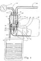
次に図1を参照すると、幾つかの異なる機能を実行するために使用される3室キャニスタ10を含む真空ポンプが提供される。3室キャニスタ10は、その第1室1に入口11を有する。吸引チューブ・カテーテル12が入口11に接続される。第2室18内では、真空排気口13が真空ゲージ14に接続される。第3室18内では、空気排出出口15があり、これは雰囲気に対して開放されている。第1室1は篩16を含み、これは固体17が「液体室」とも呼ばれる第2室18に入るのを防止する。2つの逆止め傘形弁19および20が、それぞれ第2室18および第3室21の底部にある。第3室21は大気圧であり、液体出口22を有する。3室キャニスタ10の底部には、装着ベース23が取り付けられ、これはキャニスタおよび関連のチューブ12を駆動ハウジング40に、または駆動ハウジングに接続したドッキング手段に装着するために使用する。装着ベース23は、薄膜を3室キャニスタ10の下側に固定するのにも使用する。薄膜24は棒形の一体駆動部材25を有し、これは受器・ロッド26の対応する空隙に挿入され、軸受け28に結合したクランク27を介して旋回自在にモータ39に取り付けられる。モータ39を起動すると、クランク28がモータ39によって回転し、これは受器・ロッド26を往復させ、これによって薄膜24は、これによって形成されるキャビティ29の容積を増減させる。これは自身内に真空を生成し、逆止め傘形弁19および20を通過する空気または流体をこれに向かって吸い込み、したがって給送することができる。
Referring now to FIG. 1, a vacuum pump is provided that includes a three-
好ましい実施形態は、薄膜24を往復運動させる手段としてモータとクランクの組合せについて説明するが、薄膜の往復運動を生成するために他の駆動手段を使用できることが明白である。
Although the preferred embodiment describes a motor and crank combination as means for reciprocating the
空気、液体および固体は、吸引チューブ12を通って3室キャニスタ10に入り、チューブは例示により嘔吐物を除去するために患者の口に挿入することができる。給送される3状態の物質は、入口11を通って3室キャニスタ10に入る。固体17は、篩16の手段によって第1室1よりさらに移動することができない。液体および空気は第2室(液体室)18に入り、これは薄膜24の往復運動時に真空下にあり、これを逆止め傘形弁20に通して第3室21に入れる。液体室18内の真空レベルは、導管30を介して真空排出口13に接続された真空ゲージ14によって監視される。第3室21に入った空気と液体が分離され、ここで液体は排出チューブ32を通して廃棄物袋31に排出され、空気は空気放出出口15を通って雰囲気へと追い出される。
Air, liquid and solid enter the three-
以上の記述から、3室キャニスタ10はポンプの心臓部であり、これに薄膜24を取り付けて、逆止め傘形弁19および20とともにポンプ機能を実行することが明白である。3室キャニスタを構成する3つの室のうち、1つのみ、つまり液体室18が真空となる。3室キャニスタは、篩16によって区切られ、第1室1および第3室21は基本的に大気圧である。
From the foregoing, it is clear that the three
本明細書で説明するポンプは、液体、固体および空気または3つの混合物を吸引し、3つの物質タイプそれぞれを個々の送付先へと分離する能力において特異である。吸引した固体でポンプが閉塞するのを防止して、処分するために気体ではなく液体のみを収集し、したがって処分する廃棄材料の体積を、およびこの廃棄材料を保持するキャニスタの容積を最小にするため、3タイプの物質が分離される。空気および液体は、給送される液体を含む廃棄物袋31の容積によってのみ制限される任意の体積で、連続的にポンプを通して給送できることも特に重要である。
The pumps described herein are unique in their ability to aspirate liquids, solids and air or three mixtures and separate each of the three substance types into individual destinations. Prevent the pump from becoming clogged with aspirated solids and collect only liquid, not gas, for disposal, thus minimizing the volume of waste material to be disposed of and the volume of the canister holding this waste material Therefore, three types of substances are separated. It is also particularly important that the air and liquid can be continuously pumped through any pump in any volume limited only by the volume of the
空気および液体を給送するポンプの能力は、1タイプの物質のみを給送するのに効率的である点で従来のポンプとは異なり、薄膜24が可撓性であることによって強化される。ピストンまたはリブによって硬質化されて、排除量を減少させる過度の屈曲を防止する従来のポンプの薄膜とは異なり、本発明で記載される薄膜24は特に可撓性であり、したがって液体の給送時などに存在するような重い負荷に遭遇すると、降伏することができる。この薄膜の可撓性は、追加的な大きい利点も提供する。つまり給送ボリューム29内の真空度が高い場合、薄膜24は伸張して、好ましい実施形態では電気モータ39を含む「駆動装置」への負荷が最小の状態で、受器・ロッド26が往復運動できるようにする。
Unlike conventional pumps, the ability of the pump to deliver air and liquid is enhanced by the flexibility of the
高い真空レベルを獲得するため、図2に示すように薄膜24が行程の上端にある場合、給送キャビティ29から全ての空気を抽出する必要がある。この機能は、従来の真空ポンプでは、液体または固体がポンプ室に入る時に、ポンプの損傷を引き起こす。ポンプの出口弁を通して十分な高速で排出できないからである。開示された本発明では、薄膜24が可撓性であるので、液体または固体が存在する結果として生じる抵抗に遭遇した時に、降伏するか、膨らむことができ、過度の力やその結果の損傷を防止する。
In order to obtain a high vacuum level, it is necessary to extract all the air from the
薄膜24の可撓性のさらなる重要な機能は、伸張して降伏する能力であり、したがって給送キャビティ29内の真空レベルが高い場合、薄膜24の比較的小さい有効面積のみ往復運動して伸張し、往復運動するためにモータ39から必要な出力が小さくなる。
A further important function of the flexibility of the
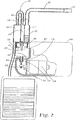
図2では、モータ39、クランク27および往復運動する受器・ロッド26を含む駆動装置ハウジング40が、他の全部品から切り離した状態で図示されている。というのは、駆動装置は再使用されるが、給送される物質と直接接触した他の部品は全て、処分するよう予定され、「使い捨てポンプ・システム」と呼ばれる。使い捨てポンプ・システムは、基本的にキャニスタ、薄膜、関連の弁、使い捨ての廃棄物袋、および関連のチューブを含み、処分するために全ての出口を密封した後の状態で、図2に図示されている。吸引チューブ12は、栓33で閉塞され、液体が漏出するのを防止する。導管30は、真空ゲージ14(図1)から切り離されて、空気排出出口15に取り付けられ、3室キャニスタ10から漏れる可能性がある通路を全て密封する。
In FIG. 2, a
好ましい実施形態で唯一の使い捨てでないハードウェアである駆動装置40は、給送される媒質のいずれとも接触しないことが、当業者には理解される。これは、吸引した空気が通過し、したがって感染性空気で汚染されているかもしれない従来の吸引器または吸引ポンプとは異なる。
Those skilled in the art will appreciate that the
使い捨てポンプ・システムを駆動装置40に取り付けて装着する方法および手段が、図2および図3に図示され、これにより装着ベース23が、図2に示すようにリテーナ41の上部に配置される。リテーナ41は駆動装置40の棚または階段状部品から突出して、大きいマッシュルーム形の頭部を有し、これは図3にも見られるベース23のフランジにある比較的大きい開口を通過する。3室キャニスタ10を、装着ベースとともに時計回りに回転すると、リテーナ41の大きい頭部がスロット45(図3)と係合し、45°の捻りを用いて差し込みタイプの締め付け動作で装着ベース23を駆動装置40に取り付ける。この動作は、キャップをガラス瓶に取り付けるのと同様である。図1および図2に示す駆動部材は、装着ベース23を駆動装置ハウジング40に取り付けるのと同時に、受器・ロッド26に挿入する。
The method and means for attaching and mounting the disposable pump system to the
図4を参照すると、ばね式ロック・クリップ46が、駆動部材25にあり予め整列したスロット48および受器・ロッド26と係合すると、ロック・クリップは、駆動部材25を受器・ロッド26に締め付けて、ロックする。装着ベース23の駆動装置40からの切り離しは、駆動部材25の受器・ロッド26からの切り離しと同時に、図4で示すように駆動部材25でロック・クリップ46をそのスロット47から押し出すことにより、両者を反時計回りに回転して実行し、駆動部材25と受器・ロッド26間の締め付けを解消する。この動作は、反時計回りに捻って持ち上げることにより、瓶からキャップを外すのと同様である。
Referring to FIG. 4, when the spring-loaded
本発明の好ましい実施形態では、キャニスタ10を駆動装置40に係合するために一つの形態しか説明していないが、これらの部品を迅速に締め付ける他の同様の方法を効果的に使用できることが、当業者には明白である。
Although the preferred embodiment of the present invention describes only one form for engaging the
しかし、上述した係合方法は、留意すべき重要な特徴を有する。受器・ロッド26は、駆動部材25が挿入された時にその下位置にあるので、スロット48および48は、モータ29に通電され、クランク27(図1および図2)が受器・ロッド26を上昇させ、ロック・クリップ46がスロット47および48を締め付けられるようにした場合のみ整列する。したがって、駆動部材25を受器・ロッド26に挿入することにより、2つを相互に締め付けるのではなく、係合させることができる。
However, the engagement method described above has important features to note. Since the receiver /
本発明は、以上で例示により図示し、説明したことによって制限されないことが、当業者には理解される。むしろ、本発明の範囲は、請求の範囲によってのみ制限される。 It will be appreciated by persons skilled in the art that the present invention is not limited by what has been shown and described by way of illustration. Rather, the scope of the present invention is limited only by the claims.
Claims (7)
前記ポンプ・ユニットおよび前記駆動ユニットは、前記ポンプ・ユニットを前記駆動ユニットに取り付けると、前記ポンプ部材および前記駆動要素が、少なくとも前記駆動ユニットの動作中に、前記駆動要素と前記ポンプ部材とが結合され更に前記駆動要素によって前記ポンプ部材を往復運動させる位置になるよう構築され、ポンプ装置は更に、前記ポンプ出口に接続されて前記ポンプ・ユニットにより給送される物質を収容する廃棄物容器を有し、
前記ポンプ部材は、前記ポンプ室に固定された周囲と、中心とを備える可撓性の薄膜であり、前記ポンプ室は、前記中心が遠位位置へと移動すると、最大容積まで膨脹することができ、前記中心が近位位置へと移動すると、最小容積まで収縮することができ、
前記可撓性の薄膜は、前記中心が前記遠位位置に近づき、前記ポンプ室を充填する流体の量が前記最大容積より小さくなると、降伏するよう伸張可能であり、それによって前記駆動ユニットが前記遠位位置を通して前記ポンプ部材を往復運動させることができる装置。A pump device comprising a drive unit with a motor connected to a drive element and a pump unit attachable to and detachable from the drive unit, wherein the pump unit comprising a pump inlet and a pump outlet comprises a pump And a reciprocable pump member, the pump member defining a portion of the pump chamber, and the pump chamber is fed by bi-directional forced reciprocation of the pump member in operation of the drive unit In order to expand and contract
When the pump unit and the drive unit are attached to the drive unit, the pump member and the drive element are coupled to each other at least during operation of the drive unit. The pump device is further constructed to reciprocate the pump member by the drive element, and the pump device further includes a waste container connected to the pump outlet and containing a substance fed by the pump unit. And
The pump member is a flexible thin film having a periphery fixed to the pump chamber and a center, and the pump chamber may expand to a maximum volume when the center moves to a distal position. And when the center moves to a proximal position, it can contract to a minimum volume,
Thin film of said flexible, the center approaches the distal position, the amount of fluid filling the pump chamber is less than the maximum volume is extensible to yield, whereby the drive unit A device capable of reciprocating the pump member through the distal position.
下端に流体入口を有する第1区画を含み、前記流体入口が、第1逆止め弁を介して前記ポンプ室と連絡し、これにより流体が前記ポンプ室に流入することだけができ、さらに、
流体出口を有する第2区画を含み、前記第2区画が、第2逆止め弁を介して下端にて前記ポンプ室と連絡し、これにより流体が前記ポンプ室から流出することだけができるポンプ・ユニット。An attachable and detachable pump unit for use with the apparatus of claim 1, further comprising:
Including a first compartment having a fluid inlet at a lower end, wherein the fluid inlet communicates with the pump chamber via a first check valve so that fluid can only flow into the pump chamber;
A pump comprising a second compartment having a fluid outlet, wherein the second compartment communicates with the pump chamber at a lower end via a second check valve, whereby fluid can only flow out of the pump chamber unit.
Applications Claiming Priority (2)
| Application Number | Priority Date | Filing Date | Title |
|---|---|---|---|
| GB0119811A GB2378734A (en) | 2001-08-14 | 2001-08-14 | Disposable pump with detachable motor |
| PCT/IL2002/000661 WO2003016719A1 (en) | 2001-08-14 | 2002-08-12 | A compact vacuum pump |
Related Child Applications (1)
| Application Number | Title | Priority Date | Filing Date |
|---|---|---|---|
| JP2009127552A Division JP2009264385A (en) | 2001-08-14 | 2009-05-27 | Compact vacuum pump |
Publications (3)
| Publication Number | Publication Date |
|---|---|
| JP2005500455A JP2005500455A (en) | 2005-01-06 |
| JP2005500455A5 JP2005500455A5 (en) | 2006-01-05 |
| JP4372546B2 true JP4372546B2 (en) | 2009-11-25 |
Family
ID=9920377
Family Applications (2)
| Application Number | Title | Priority Date | Filing Date |
|---|---|---|---|
| JP2003520985A Expired - Fee Related JP4372546B2 (en) | 2001-08-14 | 2002-08-12 | Small vacuum pump |
| JP2009127552A Abandoned JP2009264385A (en) | 2001-08-14 | 2009-05-27 | Compact vacuum pump |
Family Applications After (1)
| Application Number | Title | Priority Date | Filing Date |
|---|---|---|---|
| JP2009127552A Abandoned JP2009264385A (en) | 2001-08-14 | 2009-05-27 | Compact vacuum pump |
Country Status (8)
| Country | Link |
|---|---|
| US (6) | US7284965B2 (en) |
| EP (1) | EP1427939B1 (en) |
| JP (2) | JP4372546B2 (en) |
| AT (1) | ATE425360T1 (en) |
| CA (1) | CA2457658C (en) |
| DE (2) | DE10295375T1 (en) |
| GB (1) | GB2378734A (en) |
| WO (1) | WO2003016719A1 (en) |
Families Citing this family (67)
| Publication number | Priority date | Publication date | Assignee | Title |
|---|---|---|---|---|
| US7287398B2 (en) | 2001-09-25 | 2007-10-30 | Alsius Corporation | Heating/cooling system for indwelling heat exchange catheter |
| US7625362B2 (en) * | 2003-09-16 | 2009-12-01 | Boehringer Technologies, L.P. | Apparatus and method for suction-assisted wound healing |
| US7814021B2 (en) | 2003-01-23 | 2010-10-12 | Verdasys, Inc. | Managed distribution of digital assets |
| US8191909B2 (en) | 2005-01-10 | 2012-06-05 | Livengood Engineering, Inc. | Modular patient support system |
| WO2006074473A2 (en) | 2005-01-10 | 2006-07-13 | Livengood Engineering, Inc. | Modular patient support system |
| US9068567B2 (en) * | 2005-06-23 | 2015-06-30 | Graco Minnesota Inc | Reciprocating piston pump serviceable without tools |
| US7438705B2 (en) | 2005-07-14 | 2008-10-21 | Boehringer Technologies, L.P. | System for treating a wound with suction and method detecting loss of suction |
| US7857806B2 (en) * | 2005-07-14 | 2010-12-28 | Boehringer Technologies, L.P. | Pump system for negative pressure wound therapy |
| US20110077605A1 (en) * | 2005-07-14 | 2011-03-31 | Boehringer Technologies, L.P. | Pump system for negative pressure wound therapy |
| EP1909863A1 (en) | 2005-07-24 | 2008-04-16 | Carmeli Adahan | Wound closure and drainage system |
| AU2006273684A1 (en) * | 2005-07-24 | 2007-02-01 | Carmeli Adahan | Suctioning system, method and kit |
| US7503910B2 (en) | 2006-02-01 | 2009-03-17 | Carmeli Adahan | Suctioning system, method and kit |
| PL1945951T3 (en) | 2005-11-09 | 2009-07-31 | Dlp Ltd | Diaphragm pump |
| US20090005746A1 (en) * | 2006-02-02 | 2009-01-01 | Brian Nielsen | Suction System |
| EP1986715A1 (en) * | 2006-02-02 | 2008-11-05 | Coloplast A/S | Pump and system for treatment of a wound |
| US20090036873A1 (en) * | 2006-02-02 | 2009-02-05 | Coloplast A/S | Device, Pump and System for Stimulating the Healing of a Wound |
| US8529530B2 (en) | 2006-05-09 | 2013-09-10 | Medela Holding Ag | Drainage pump unit |
| CA2706824C (en) | 2006-05-09 | 2014-02-04 | Medela Holding Ag | Fluid collection reservoir |
| ES2340085T5 (en) † | 2006-09-28 | 2014-04-16 | Smith & Nephew, Inc. | Portable wound therapy system |
| US9345457B2 (en) | 2006-12-13 | 2016-05-24 | Devicor Medical Products, Inc. | Presentation of biopsy sample by biopsy device |
| US9135334B2 (en) * | 2007-01-23 | 2015-09-15 | Cox Communications, Inc. | Providing a social network |
| EP3689274A1 (en) | 2007-02-05 | 2020-08-05 | Boston Scientific Limited | Thrombectomy system |
| EP2152333B1 (en) | 2007-05-07 | 2012-10-17 | Carmeli Adahan | Suction system |
| WO2008141470A1 (en) | 2007-05-22 | 2008-11-27 | Medela Holding Ag | Drainage tube unit |
| US9408954B2 (en) | 2007-07-02 | 2016-08-09 | Smith & Nephew Plc | Systems and methods for controlling operation of negative pressure wound therapy apparatus |
| GB0715259D0 (en) | 2007-08-06 | 2007-09-12 | Smith & Nephew | Canister status determination |
| TWI340653B (en) | 2007-11-09 | 2011-04-21 | Ind Tech Res Inst | Detachable pump and the negative pressure wound therapy system using the same |
| US20130096518A1 (en) | 2007-12-06 | 2013-04-18 | Smith & Nephew Plc | Wound filling apparatuses and methods |
| US11253399B2 (en) | 2007-12-06 | 2022-02-22 | Smith & Nephew Plc | Wound filling apparatuses and methods |
| US20100022990A1 (en) * | 2008-07-25 | 2010-01-28 | Boehringer Technologies, L.P. | Pump system for negative pressure wound therapy and improvements thereon |
| US9510854B2 (en) | 2008-10-13 | 2016-12-06 | Boston Scientific Scimed, Inc. | Thrombectomy catheter with control box having pressure/vacuum valve for synchronous aspiration and fluid irrigation |
| US20100099002A1 (en) * | 2008-10-21 | 2010-04-22 | Gm Global Technology Operations, Inc. | Fluid pump with an integrated mounting interface |
| DE102008044139B4 (en) * | 2008-11-27 | 2014-02-20 | Industrial Technology Research Institute | Demountable pump and vacuum wound therapy system using these |
| US8821458B2 (en) | 2010-04-16 | 2014-09-02 | Kci Licensing, Inc. | Evaporative body-fluid containers and methods |
| US8409160B2 (en) * | 2010-05-18 | 2013-04-02 | Kci Licensing, Inc. | Reduced-pressure treatment systems and methods employing a fluidly isolated pump control unit |
| GB2483281B (en) * | 2010-09-03 | 2012-11-07 | Apex Medical Corp | Negative pressure fluid absorbent system and a feedback control method for the same |
| WO2012144668A1 (en) * | 2011-04-20 | 2012-10-26 | Moon Myung Sun | Medical suction apparatus |
| DE102012017736A1 (en) * | 2012-09-09 | 2014-03-13 | Apk Aluminium Und Kunststoffe Ag | Transportable container and method for collecting recyclable waste |
| US10060565B2 (en) * | 2014-03-31 | 2018-08-28 | Hamilton Sundstrand Corporation | Fluid transfer coupling |
| US9433427B2 (en) | 2014-04-08 | 2016-09-06 | Incuvate, Llc | Systems and methods for management of thrombosis |
| US9248221B2 (en) | 2014-04-08 | 2016-02-02 | Incuvate, Llc | Aspiration monitoring system and method |
| US9883877B2 (en) | 2014-05-19 | 2018-02-06 | Walk Vascular, Llc | Systems and methods for removal of blood and thrombotic material |
| US10047737B2 (en) | 2014-07-08 | 2018-08-14 | Flow Control LLC | Pump head coupling with twist-lock connections |
| CN110725793B (en) | 2014-12-30 | 2022-06-28 | 固瑞克明尼苏达有限公司 | Integrated mounting system on axial reciprocating pump |
| DE102015103250A1 (en) * | 2015-03-05 | 2016-09-08 | Prominent Gmbh | Dosing device with removable dosing head |
| USD787073S1 (en) | 2015-03-12 | 2017-05-16 | Lgms, Llc | Patient support cart with mounting plate |
| USD783389S1 (en) | 2015-03-12 | 2017-04-11 | Lgms, Llc | Mounting plate for a patient support cart |
| US10702292B2 (en) | 2015-08-28 | 2020-07-07 | Incuvate, Llc | Aspiration monitoring system and method |
| US10561440B2 (en) | 2015-09-03 | 2020-02-18 | Vesatek, Llc | Systems and methods for manipulating medical devices |
| CA2997832A1 (en) * | 2015-09-10 | 2017-03-16 | Excitus As | Arrangements and methods for avoiding spreading of infectious agents and improving electric safety and suction performance of a medical aspirator |
| US20170100142A1 (en) | 2015-10-09 | 2017-04-13 | Incuvate, Llc | Systems and methods for management of thrombosis |
| US10226263B2 (en) | 2015-12-23 | 2019-03-12 | Incuvate, Llc | Aspiration monitoring system and method |
| US10492805B2 (en) | 2016-04-06 | 2019-12-03 | Walk Vascular, Llc | Systems and methods for thrombolysis and delivery of an agent |
| WO2017192919A1 (en) * | 2016-05-04 | 2017-11-09 | Board Of Regents Of The University Of Texas System | Airway suction device |
| EP3452721B1 (en) | 2016-05-06 | 2020-04-15 | Graco Minnesota Inc. | Mechanically driven modular diaphragm pump |
| BR102018003284B1 (en) | 2017-02-21 | 2021-07-20 | Graco Minnesota Inc. | PISTON ROD FOR A PUMP, PUMP, SPRAYER, AND METHOD FOR REPLACING A WEAR GLOVE |
| JP6843676B2 (en) * | 2017-03-30 | 2021-03-17 | 日本発條株式会社 | Agent supply method and target structure |
| GB201718647D0 (en) * | 2017-11-10 | 2017-12-27 | Teleflex Life Sciences Unlimited Co | Medical container |
| CN108612640A (en) * | 2018-06-04 | 2018-10-02 | 湖南宇诚精密科技有限公司 | a kind of vacuum generating device |
| CN108939178B (en) * | 2018-06-07 | 2022-03-04 | 西安交通大学医学院第一附属医院 | Suction device for abdominal surgery |
| US11678905B2 (en) | 2018-07-19 | 2023-06-20 | Walk Vascular, Llc | Systems and methods for removal of blood and thrombotic material |
| CN109675128A (en) * | 2019-01-14 | 2019-04-26 | 刘桂萍 | A kind of medical atomization suction sputum equipment of department of general surgery |
| CN115362318A (en) | 2020-03-31 | 2022-11-18 | 固瑞克明尼苏达有限公司 | Pump drive system |
| CN112972785B (en) * | 2021-02-05 | 2022-03-08 | 吉林大学 | Efficient multifunctional aspirator special for brain surgery |
| US12085066B2 (en) * | 2021-02-23 | 2024-09-10 | Ventriflo, Inc. | Pulsatile fluid pump system |
| DE102021134629B4 (en) | 2021-12-23 | 2024-05-29 | KNF Micro AG | Pump head for a diaphragm pump |
| CN116077747B (en) * | 2022-12-29 | 2023-11-24 | 挪度医疗器械(苏州)有限公司 | Low-noise negative pressure sputum aspirator |
Family Cites Families (38)
| Publication number | Priority date | Publication date | Assignee | Title |
|---|---|---|---|---|
| US3811803A (en) | 1968-10-23 | 1974-05-21 | Pierburg A Auto Und Luftfahrtg | Diaphragm pump |
| US3981636A (en) | 1973-07-20 | 1976-09-21 | Toyota Jidosha Kogyo Kabushiki Kaisha | Diaphragm vacuum pump |
| JPS5252465A (en) | 1975-10-27 | 1977-04-27 | Tax Adm Agency | Method for fruit wine brewery-waste treatment |
| CA1110137A (en) | 1976-05-24 | 1981-10-06 | Ingemar H. Lundquist | Intravenous liquid pumping system and method |
| DE2712552C2 (en) * | 1977-03-22 | 1979-05-17 | Joachim Dipl.-Ing. 4630 Bochum Teichmann | Magnetic piston pump for pumping fluids |
| JPS5535118A (en) | 1978-08-31 | 1980-03-12 | Matsushita Electric Works Ltd | Driving shaft fixing apparatus of diaphragm pump |
| US4339211A (en) | 1979-07-30 | 1982-07-13 | Exxon Research & Engineering Co. | Flexible leader |
| JPS5627384U (en) | 1979-08-04 | 1981-03-13 | ||
| JPS5690486U (en) | 1979-12-13 | 1981-07-18 | ||
| JPS5690486A (en) | 1979-12-24 | 1981-07-22 | Nec Corp | Magnetic bubble element |
| DE3327716A1 (en) * | 1982-08-02 | 1984-02-02 | Medtronic, Inc., 55440 Minneapolis, Minn. | ARRANGEMENT WITH A DC MOTOR AND DIAPHRAGM PUMP |
| US4635621A (en) | 1982-12-01 | 1987-01-13 | Snyder Laboratories, Inc. | Lavage system with replaceable pump |
| US4570833A (en) * | 1983-08-26 | 1986-02-18 | Vanderjagt John A | Pumping system |
| JPS60127489A (en) | 1983-12-14 | 1985-07-08 | 株式会社東芝 | Fuel aggregate |
| DE3347538A1 (en) | 1983-12-30 | 1985-07-11 | KNF Neuberger GmbH, 7800 Freiburg | DIAPHRAGM PUMP |
| DE3441891A1 (en) | 1984-11-16 | 1986-05-28 | Walter Beck | METHOD AND DEVICE FOR SUCTIONING SECRETARY LIQUID FROM A Wound |
| JPS6298864A (en) | 1985-10-24 | 1987-05-08 | Konishiroku Photo Ind Co Ltd | Fitting device for image sensor |
| JPS6298864U (en) | 1985-12-11 | 1987-06-24 | ||
| US4639245A (en) * | 1985-12-20 | 1987-01-27 | Oximetrix, Inc. | Fluid infusion pump driver |
| US4747843A (en) | 1986-05-15 | 1988-05-31 | C.R. Bard, Inc. | Control module for thoracic drainage apparatus |
| DE3632358A1 (en) | 1986-09-24 | 1988-03-31 | Bayer Ag | ESTER AND ETHER GROUPS CONTAINING POLYHYDROXYL COMPOUNDS AS REACTIVE THINNERS |
| DE3706338A1 (en) * | 1987-02-27 | 1988-09-08 | Wagner Gmbh J | DIAPHRAGM PUMP DEVICE |
| US4842584A (en) * | 1987-05-01 | 1989-06-27 | Abbott Laboratories | Disposable fluid infusion pumping chamber cassette and drive mechanism thereof |
| US4798589A (en) * | 1987-06-15 | 1989-01-17 | Fisher Scientific Group Inc. | Diaphragm pump cassette |
| IL83259A (en) * | 1987-07-20 | 1992-05-25 | D F Lab Ltd | Disposable cell and diaphragm pump for use of same |
| US4883476A (en) * | 1988-01-07 | 1989-11-28 | Bioresearch, Inc. | Drainage device with disposable collection chamber |
| US5021048A (en) * | 1989-08-04 | 1991-06-04 | Medtronic, Inc. | Blood pump drive system |
| JP2505726Y2 (en) | 1990-03-05 | 1996-07-31 | 株式会社三鈴エリー | Disposal piezoelectric pump |
| US5165866A (en) * | 1990-12-07 | 1992-11-24 | Iwaki Co., Ltd. | Bellows pump |
| US5173033A (en) | 1990-12-11 | 1992-12-22 | Adahan Inc. | One-way umbrella valve and portable fluid pumping device including same |
| JPH05231329A (en) | 1992-02-20 | 1993-09-07 | Shigeo Kai | Liquid container with compact measuring discharge pump and pump driving device of the container |
| US5466229A (en) | 1993-08-06 | 1995-11-14 | Davstar, Inc. | Fluid collection system |
| US5419687A (en) | 1994-02-28 | 1995-05-30 | Adahan; Carmeli | Fluid pump and suction pump assembly including same |
| US5645540A (en) * | 1994-10-11 | 1997-07-08 | Stryker Corporation | Blood conservation system |
| US6135725A (en) * | 1996-09-11 | 2000-10-24 | Chou; Wen-San | Valved piston arrangement for an electric motor driven air compressor |
| US6315534B1 (en) | 1998-03-30 | 2001-11-13 | Wen San Chou | Air compressor having easily assembled structure |
| JP2000064957A (en) | 1998-08-17 | 2000-03-03 | Toyota Autom Loom Works Ltd | Variable displacement swash prate compressor and extraction side control valve |
| DE19916876A1 (en) * | 1999-04-14 | 2000-11-02 | Clemens Micheler | Medical dosing pump |
-
2001
- 2001-08-14 GB GB0119811A patent/GB2378734A/en not_active Withdrawn
-
2002
- 2002-08-12 WO PCT/IL2002/000661 patent/WO2003016719A1/en active Application Filing
- 2002-08-12 US US10/486,940 patent/US7284965B2/en not_active Expired - Fee Related
- 2002-08-12 CA CA2457658A patent/CA2457658C/en not_active Expired - Fee Related
- 2002-08-12 DE DE10295375T patent/DE10295375T1/en not_active Withdrawn
- 2002-08-12 JP JP2003520985A patent/JP4372546B2/en not_active Expired - Fee Related
- 2002-08-12 DE DE60231520T patent/DE60231520D1/en not_active Expired - Lifetime
- 2002-08-12 AT AT02758763T patent/ATE425360T1/en active
- 2002-08-12 EP EP02758763A patent/EP1427939B1/en not_active Expired - Lifetime
-
2006
- 2006-09-29 US US11/529,388 patent/US7758539B2/en not_active Expired - Fee Related
-
2007
- 2007-02-26 US US11/710,494 patent/US20070166180A1/en not_active Abandoned
- 2007-05-04 US US11/797,555 patent/US20070269321A1/en not_active Abandoned
- 2007-09-05 US US11/896,674 patent/US7918654B2/en not_active Expired - Fee Related
- 2007-10-30 US US11/976,935 patent/US20080056915A1/en not_active Abandoned
-
2009
- 2009-05-27 JP JP2009127552A patent/JP2009264385A/en not_active Abandoned
Also Published As
| Publication number | Publication date |
|---|---|
| JP2009264385A (en) | 2009-11-12 |
| US20070166180A1 (en) | 2007-07-19 |
| US20080056915A1 (en) | 2008-03-06 |
| US20040208756A1 (en) | 2004-10-21 |
| JP2005500455A (en) | 2005-01-06 |
| EP1427939B1 (en) | 2009-03-11 |
| WO2003016719A1 (en) | 2003-02-27 |
| EP1427939A1 (en) | 2004-06-16 |
| US20070297924A1 (en) | 2007-12-27 |
| DE60231520D1 (en) | 2009-04-23 |
| CA2457658A1 (en) | 2003-02-27 |
| US7918654B2 (en) | 2011-04-05 |
| US20070031268A1 (en) | 2007-02-08 |
| EP1427939A4 (en) | 2005-06-22 |
| DE10295375T1 (en) | 2003-11-06 |
| GB2378734A (en) | 2003-02-19 |
| CA2457658C (en) | 2010-04-06 |
| ATE425360T1 (en) | 2009-03-15 |
| GB0119811D0 (en) | 2001-10-10 |
| US7758539B2 (en) | 2010-07-20 |
| US20070269321A1 (en) | 2007-11-22 |
| US7284965B2 (en) | 2007-10-23 |
Similar Documents
| Publication | Publication Date | Title |
|---|---|---|
| JP4372546B2 (en) | Small vacuum pump | |
| US3841331A (en) | Suction-pump assembly for drawing body fluids | |
| EP2127690B2 (en) | Wound closure and drainage system | |
| CN106232020B (en) | Suction unit | |
| CA2581512C (en) | Cassette having elastomeric clamping ribs | |
| JP6165188B2 (en) | Pump device, tube device and system for peristaltic movement of fluid | |
| CN110743262B (en) | Integrated intra-cavity gas circulation treatment device for laparoscopic surgery | |
| JP2009525088A (en) | Suction system | |
| US6135980A (en) | Mucus suction device | |
| JPH11342194A (en) | Suction device for medical use | |
| JP2016527021A (en) | Blood concentrator | |
| AU2007201048A1 (en) | Wound closure and drainage system | |
| EP0378296A2 (en) | Suction pump assemblies | |
| EP3192535B1 (en) | Container for drainage of fluids or wound secretion | |
| US20050002810A1 (en) | Portable vacuum system | |
| US20080097410A1 (en) | Medical fluid aspirator | |
| CN208114838U (en) | A kind of Novel baby sputum aspirator | |
| SE432876B (en) | Device for portioning out a solution from a container |
Legal Events
| Date | Code | Title | Description |
|---|---|---|---|
| A521 | Request for written amendment filed |
Free format text: JAPANESE INTERMEDIATE CODE: A523 Effective date: 20050808 |
|
| A621 | Written request for application examination |
Free format text: JAPANESE INTERMEDIATE CODE: A621 Effective date: 20050808 |
|
| A131 | Notification of reasons for refusal |
Free format text: JAPANESE INTERMEDIATE CODE: A131 Effective date: 20080610 |
|
| A601 | Written request for extension of time |
Free format text: JAPANESE INTERMEDIATE CODE: A601 Effective date: 20080910 |
|
| A602 | Written permission of extension of time |
Free format text: JAPANESE INTERMEDIATE CODE: A602 Effective date: 20080918 |
|
| A521 | Request for written amendment filed |
Free format text: JAPANESE INTERMEDIATE CODE: A523 Effective date: 20081208 |
|
| A02 | Decision of refusal |
Free format text: JAPANESE INTERMEDIATE CODE: A02 Effective date: 20090217 |
|
| A521 | Request for written amendment filed |
Free format text: JAPANESE INTERMEDIATE CODE: A523 Effective date: 20090518 |
|
| A521 | Request for written amendment filed |
Free format text: JAPANESE INTERMEDIATE CODE: A523 Effective date: 20090527 |
|
| A521 | Request for written amendment filed |
Free format text: JAPANESE INTERMEDIATE CODE: A821 Effective date: 20090519 |
|
| A911 | Transfer to examiner for re-examination before appeal (zenchi) |
Free format text: JAPANESE INTERMEDIATE CODE: A911 Effective date: 20090626 |
|
| TRDD | Decision of grant or rejection written | ||
| A01 | Written decision to grant a patent or to grant a registration (utility model) |
Free format text: JAPANESE INTERMEDIATE CODE: A01 Effective date: 20090807 |
|
| A01 | Written decision to grant a patent or to grant a registration (utility model) |
Free format text: JAPANESE INTERMEDIATE CODE: A01 |
|
| A61 | First payment of annual fees (during grant procedure) |
Free format text: JAPANESE INTERMEDIATE CODE: A61 Effective date: 20090902 |
|
| FPAY | Renewal fee payment (event date is renewal date of database) |
Free format text: PAYMENT UNTIL: 20120911 Year of fee payment: 3 |
|
| R150 | Certificate of patent or registration of utility model |
Free format text: JAPANESE INTERMEDIATE CODE: R150 |
|
| FPAY | Renewal fee payment (event date is renewal date of database) |
Free format text: PAYMENT UNTIL: 20120911 Year of fee payment: 3 |
|
| FPAY | Renewal fee payment (event date is renewal date of database) |
Free format text: PAYMENT UNTIL: 20130911 Year of fee payment: 4 |
|
| LAPS | Cancellation because of no payment of annual fees |