EP0378296A2 - Suction pump assemblies - Google Patents
Suction pump assemblies Download PDFInfo
- Publication number
- EP0378296A2 EP0378296A2 EP90300059A EP90300059A EP0378296A2 EP 0378296 A2 EP0378296 A2 EP 0378296A2 EP 90300059 A EP90300059 A EP 90300059A EP 90300059 A EP90300059 A EP 90300059A EP 0378296 A2 EP0378296 A2 EP 0378296A2
- Authority
- EP
- European Patent Office
- Prior art keywords
- container
- plate
- pump
- fluid
- assembly according
- Prior art date
- Legal status (The legal status is an assumption and is not a legal conclusion. Google has not performed a legal analysis and makes no representation as to the accuracy of the status listed.)
- Withdrawn
Links
Images

Classifications
-
- A—HUMAN NECESSITIES
- A61—MEDICAL OR VETERINARY SCIENCE; HYGIENE
- A61M—DEVICES FOR INTRODUCING MEDIA INTO, OR ONTO, THE BODY; DEVICES FOR TRANSDUCING BODY MEDIA OR FOR TAKING MEDIA FROM THE BODY; DEVICES FOR PRODUCING OR ENDING SLEEP OR STUPOR
- A61M1/00—Suction or pumping devices for medical purposes; Devices for carrying-off, for treatment of, or for carrying-over, body-liquids; Drainage systems
- A61M1/71—Suction drainage systems
- A61M1/78—Means for preventing overflow or contamination of the pumping systems
- A61M1/784—Means for preventing overflow or contamination of the pumping systems by filtering, sterilising or disinfecting the exhaust air, e.g. swellable filter valves
-
- A—HUMAN NECESSITIES
- A61—MEDICAL OR VETERINARY SCIENCE; HYGIENE
- A61M—DEVICES FOR INTRODUCING MEDIA INTO, OR ONTO, THE BODY; DEVICES FOR TRANSDUCING BODY MEDIA OR FOR TAKING MEDIA FROM THE BODY; DEVICES FOR PRODUCING OR ENDING SLEEP OR STUPOR
- A61M1/00—Suction or pumping devices for medical purposes; Devices for carrying-off, for treatment of, or for carrying-over, body-liquids; Drainage systems
- A61M1/64—Containers with integrated suction means
- A61M1/68—Containers incorporating a flexible member creating suction
-
- A—HUMAN NECESSITIES
- A61—MEDICAL OR VETERINARY SCIENCE; HYGIENE
- A61M—DEVICES FOR INTRODUCING MEDIA INTO, OR ONTO, THE BODY; DEVICES FOR TRANSDUCING BODY MEDIA OR FOR TAKING MEDIA FROM THE BODY; DEVICES FOR PRODUCING OR ENDING SLEEP OR STUPOR
- A61M1/00—Suction or pumping devices for medical purposes; Devices for carrying-off, for treatment of, or for carrying-over, body-liquids; Drainage systems
- A61M1/80—Suction pumps
- A61M1/82—Membrane pumps, e.g. bulbs
-
- A—HUMAN NECESSITIES
- A61—MEDICAL OR VETERINARY SCIENCE; HYGIENE
- A61M—DEVICES FOR INTRODUCING MEDIA INTO, OR ONTO, THE BODY; DEVICES FOR TRANSDUCING BODY MEDIA OR FOR TAKING MEDIA FROM THE BODY; DEVICES FOR PRODUCING OR ENDING SLEEP OR STUPOR
- A61M1/00—Suction or pumping devices for medical purposes; Devices for carrying-off, for treatment of, or for carrying-over, body-liquids; Drainage systems
- A61M1/60—Containers for suction drainage, adapted to be used with an external suction source
- A61M1/604—Bag or liner in a rigid container, with suction applied to both
-
- A—HUMAN NECESSITIES
- A61—MEDICAL OR VETERINARY SCIENCE; HYGIENE
- A61M—DEVICES FOR INTRODUCING MEDIA INTO, OR ONTO, THE BODY; DEVICES FOR TRANSDUCING BODY MEDIA OR FOR TAKING MEDIA FROM THE BODY; DEVICES FOR PRODUCING OR ENDING SLEEP OR STUPOR
- A61M2205/00—General characteristics of the apparatus
- A61M2205/75—General characteristics of the apparatus with filters
- A61M2205/7518—General characteristics of the apparatus with filters bacterial
-
- A—HUMAN NECESSITIES
- A61—MEDICAL OR VETERINARY SCIENCE; HYGIENE
- A61M—DEVICES FOR INTRODUCING MEDIA INTO, OR ONTO, THE BODY; DEVICES FOR TRANSDUCING BODY MEDIA OR FOR TAKING MEDIA FROM THE BODY; DEVICES FOR PRODUCING OR ENDING SLEEP OR STUPOR
- A61M2205/00—General characteristics of the apparatus
- A61M2205/75—General characteristics of the apparatus with filters
- A61M2205/7536—General characteristics of the apparatus with filters allowing gas passage, but preventing liquid passage, e.g. liquophobic, hydrophobic, water-repellent membranes
Definitions
- This invention relates to suction pump assemblies of the kind including a fluid collection container and a pump coupled with the container for drawing fluid into the container for collection therein and subsequent disposal.
- the invention is more particularly concerned with suction pump assemblies for medico-surgical or other applications where hazardous fluids are collected.
- a pump is interconnected via tubing to an outlet provided near the top of a collection jar.
- An inlet to the collection jar is connected via tubing to a suction catheter which the surgeon applies to the surgical site to remove blood, aspirating fluid, tissue debris or the like.
- the pump draws air out of the collection jar, creating a reduced pressure which causes the fluid to be sucked along the catheter tubing into the jar.
- the collection jar is full, it is disconnected from the pump and disposed of.
- some form of bacterial filter is connected between the collection jar and the pump to prevent contamination of the pump and atmosphere by bacteria.
- a suction pump assembly of the above-specified kind characterised in that the pump includes a first substantially rigid plate secured around its edge to the container and a one-way valve establishing fluid communication between the container and the pump, a second flexible diaphragm plate sealed arround its edge with the first plate and defining between the first and second plates a pump chamber of variable volume, and a drive unit for applying osciallatory movement to the second plate so as to vary the volume of the pump chamber and thereby cause fluid to be drawn into the container, at least the container and first plate being readily removable from the drive unit so that the container and its contents can be removed and disposed of, with the first plate providing a cover for the container.
- the pump creates a reduced air pressure in the container so that fluid is drawn into the container through a passage not including the pump chamber, the one-way valve allowing gas out of the container but preventing gas entering the container, and the second plate including a one-way valve that allows gas to leave the pump chamber but prevents gas entering the pump chamber.
- the first plate preferably has a vent tube which extends to the one-way valve and through which gas is withdrawn from the container, the lower end of the vent tube defining the maximum filling level of the container.
- the assembly may include a filter which is permeable to gas but impermeable to liquid, the filter being in line with the one-way valve.
- the pump may include a fluid inlet spigot formed with the first plate.
- suction fluid flows into the container through the pump chamber, and the one-way valve allows fluid to flow into the container from the pump chamber but prevents flow in the opposite direction.
- the container may be a flexible bag.
- the first plate may be detachable from the second plate, the second plate being retained with the drive unit and the first plate being disposed of with the container.
- the assembly preferably includes an outer housing within which the container is located, the outer housing including a clip that holds the pump on the housing and holds the first and second plates together.
- the second plate may alternatively be permanently secured with the first plate such that the second plate is disposed of with the first plate.
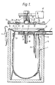
- the suction pump assembly comprises a collection jar 1 and a diaphragm pump 2 which creates a reduced pressure in the jar to draw fluid into the jar from a suction catheter, via tubing 3.
- the jar 1 is of circular section with a capacity of two litres and is preferably moulded from an inexpensive, transparent plastics material so that it can be disposed of when full.
- the jar 1 is supported within an outer housing 10 of a rigid material.
- the outer housing 10 is also preferably transparent, or has a transparent window, so that the filling level of the jar 1 can be monitored.
- toggle fasteners 11 At its upper end, toggle fasteners 11, only one of which is shown, are mounted on the outer surface of the housing which serve to secure the jar 1 and the diaphragm pump 2 to the housing 10.
- the pump 2 has a rigid lower plate member 20 moulded from a plastics material.
- the plate 20 is of generally dish shape with a shallow concave recess 21 on its upper surface.
- the lower surface of the outer edge of the plate 20 rests on the top of the housing 10, the upper surface of the plate having an upwardly projecting wall 22 around its edge.
- the plate 20 is sealed to the top of the jar 1 by means of a downwardly projecting annular channel 23 which receives the top edge of the jar and is permanently secured to it, such as by means of an adhesive or by welding.
- a spigot 24 projects radially outwardly beneath the edge of the plate and extends through a keyway 12 in the upper edge of the housing 10.
- the spigot 24 defines a fluid passageway through the plate 20 which opens into the jar 1 via a vertical inlet tube 25.
- a gas passage 26 extends into the jar 1 through the centre of the plate member 20.
- the passage 26 is sealed by a one-way valve 27 in the form of a conventional resilient flap-valve the edge on which seals on an annular shoulder 28 formed around the passage 26.
- the valve 27 allows upward flow of gas, that is, from the jar 1 into the pump 2, but prevents flow in the opposite direction.
- Beneath the valve 27 there is mounted a hydrophobic bacterial filter 29 which communicates with a short gas vent tube 30.
- the filter allow passage of gas but prevents passage of bacteria or liquids. Other gas-permeable, liquid-impermeable filters could be used.
- the pump 2 also includes an upper plate member 31 which is made of a resilient, elastomeric material such as rubber or an elastomeric plastics.
- the upper plate 31 is generally flat in its natural state and of circular shape
- a concave annular channel 32 extends around the lower surface of the outer edge of the plate 31, the channel receiving the wall 22 on the lower plate 20 in sealing engagement.
- a short distance within the edge of the upper plate 31, it is reduced in thickness and formed into two annular concentric corrugations 34.
- the central region 35 of the upper plate 31 is thicker and stiffer and supports two one-way valves 36 that overlie gas vents 37 through the plate.
- the valves 37 are conventional resilient flap valves which are arranged to allow gas to flow up through the vents 37 and out of the pump 2 but to prevent gas flow in the opposite direction.
- the drive unit 40 is a conventional oscillatory motor which is coupled to the stem 38 and moves this up and down, thereby moving the central region 35 of the upper plate 31 up and down and flexing the corrugations 34. This varies the volume of the pump chamber 39 which is defined between the upper plate 31 and the lower plate 20.
- the pump 2 and jar 1 are clamped firmly onto the housing 10 by means of the toggle fasteners 11.
- the drive unit 40 is then energized so that the central region 35 of the upper plate 31 is moved up and down, away from and towards the lower plate 20.
- Downward movement of the upper plate 31 causes an increase in pressure in the pump chamber 39 thereby closing the valve 27 and opening the valves 36 which allows air to escape from the chamber to atmosphere.
- Upward movement of the upper plate 31 causes a reduction of pressure within the chamber 39 thereby closing the valves 36 but opening the valve 27 into the jar. This causes gas in the jar 1 to be drawn through the vent tube 30 and filter 29 into the pump chamber 39.
- the user turns off the pump drive unit 40. If the fluid level should rise too far, and it enters the vent tube 30, the filter 29 will prevent it passing into the pump 2.
- the toggle fasteners 11 are now released and the jar 1, with the lower plate 20, is removed from the housing 10.
- the lower plate 20 acts as a cover for the jar 1 to prevent spillage, although preferably an additional cover will be used or some form of plug to occlude the spigot 24.
- the jar 1 and plate 20 are then disposed of and a new jar with its own lower plate are placed in the housing 10.
- the upper plate 31 is reused and clamped onto the lower plate using the toggle fasteners 11.
- Suction pump assemblies of the present invention avoid the need for any tubing between the collection jar and pump. Although the upper plate 31 may need cleaning occasionally, because of its open construction this can be readily performed, such as in an autoclave.
- the assembly described above creates a reduced pressure in the collection jar by pumping out gas from the jar. This requires the use of a jar that is rigid and can withstand the reduced pressures employed.
- FIG 2 there is shown an alternative suction pump assembly similar to that of Figure 1 but which is used directly to pump suction fluid into the container 1.
- the inlet spigot 24′ in this arrangement opens into the pump chamber 39′ via a one way valve 36′ which allows fluid into the pump chamber but prevents it leaving the chamber.
- the pump chamber 39′ communicates with the container 1′, which in this case is a flexible bag, via an inlet tube 25′ and a one-way valve 27′.
- the one-way valve 27′ allows fluid to flow from the pump chamber 39′ to the inlet tube 25′ but prevents flow in the opposite direction.
- the upper plate 31′ When the upper plate 31′ is raised, this creates a reduced pressure in the chamber 39′ which closes valve 27′ and draws fluid from the inlet spigot 24′ and catheter 3′ into the chamber. Downward movement of the upper plate 31′ closes valve 36′ and pumps the fluid in chamber 39′ via the valve 27′ and inlet tube 25′ into the container 1′. If the container 1′ was rigid, an air vent may be necessary to allow air to escape from the container as it fills with fluid. With this assembly, it is preferable that the upper plate 31′ is permanently sealed around its outer edge to the lower plate 20′, so that the entire pump 2′ is disposed of with the container 1′, further to avoid the risk of contamination.
- the container could be a flexible bag. It will be appreciated that such an assembly would be impractical with conventional, reusable pumps because of the need to sterilise the pump after each use. In the present invention, the entire would be disposed of and only the drive unit and support housing retained.
Abstract
Description
- This invention relates to suction pump assemblies of the kind including a fluid collection container and a pump coupled with the container for drawing fluid into the container for collection therein and subsequent disposal.
- The invention is more particularly concerned with suction pump assemblies for medico-surgical or other applications where hazardous fluids are collected.
- In conventional medico-surgical suction pump assemblies, a pump is interconnected via tubing to an outlet provided near the top of a collection jar. An inlet to the collection jar is connected via tubing to a suction catheter which the surgeon applies to the surgical site to remove blood, aspirating fluid, tissue debris or the like. The pump draws air out of the collection jar, creating a reduced pressure which causes the fluid to be sucked along the catheter tubing into the jar. When the collection jar is full, it is disconnected from the pump and disposed of. Preferably, some form of bacterial filter is connected between the collection jar and the pump to prevent contamination of the pump and atmosphere by bacteria. Although these filters provide a degree of protection, it is nevertheless necessary periodically to clean and sterilize the pump which is a difficult and time consuming task. There is risk that a pump infected by bacteria may be used for some time before it is next sterilized since this is not generally done after every use.
- It is an object of the present invention to provide a suction pump assembly that can be used to overcome these disadvantages.
- According to one aspect of the present invention there is provided a suction pump assembly of the above-specified kind characterised in that the pump includes a first substantially rigid plate secured around its edge to the container and a one-way valve establishing fluid communication between the container and the pump, a second flexible diaphragm plate sealed arround its edge with the first plate and defining between the first and second plates a pump chamber of variable volume, and a drive unit for applying osciallatory movement to the second plate so as to vary the volume of the pump chamber and thereby cause fluid to be drawn into the container, at least the container and first plate being readily removable from the drive unit so that the container and its contents can be removed and disposed of, with the first plate providing a cover for the container.
- In one arrangement, the pump creates a reduced air pressure in the container so that fluid is drawn into the container through a passage not including the pump chamber, the one-way valve allowing gas out of the container but preventing gas entering the container, and the second plate including a one-way valve that allows gas to leave the pump chamber but prevents gas entering the pump chamber.
- The first plate preferably has a vent tube which extends to the one-way valve and through which gas is withdrawn from the container, the lower end of the vent tube defining the maximum filling level of the container. The assembly may include a filter which is permeable to gas but impermeable to liquid, the filter being in line with the one-way valve. The pump may include a fluid inlet spigot formed with the first plate.
- In an alternative arrangement, suction fluid flows into the container through the pump chamber, and the one-way valve allows fluid to flow into the container from the pump chamber but prevents flow in the opposite direction. In this alternative arrangement, the container may be a flexible bag.
- The first plate may be detachable from the second plate, the second plate being retained with the drive unit and the first plate being disposed of with the container.
- The assembly preferably includes an outer housing within which the container is located, the outer housing including a clip that holds the pump on the housing and holds the first and second plates together.
- The second plate may alternatively be permanently secured with the first plate such that the second plate is disposed of with the first plate.
- Two forms of suction pump assemblies, in accordance with the present invention, will now be described, by way of example, with reference to the accompanying drawings, in which:
- Figure 1 is a sectional side elevation view of one form of assembly; and
- Figure 2 is a sectional side elevation view of the other form of assembly.
- With reference to Figure 1, the suction pump assembly comprises a collection jar 1 and a
diaphragm pump 2 which creates a reduced pressure in the jar to draw fluid into the jar from a suction catheter, viatubing 3. - The jar 1 is of circular section with a capacity of two litres and is preferably moulded from an inexpensive, transparent plastics material so that it can be disposed of when full. The jar 1 is supported within an
outer housing 10 of a rigid material. Theouter housing 10 is also preferably transparent, or has a transparent window, so that the filling level of the jar 1 can be monitored. At its upper end,toggle fasteners 11, only one of which is shown, are mounted on the outer surface of the housing which serve to secure the jar 1 and thediaphragm pump 2 to thehousing 10. - The
pump 2 has a rigidlower plate member 20 moulded from a plastics material. Theplate 20 is of generally dish shape with a shallowconcave recess 21 on its upper surface. The lower surface of the outer edge of theplate 20 rests on the top of thehousing 10, the upper surface of the plate having an upwardly projectingwall 22 around its edge.
Theplate 20 is sealed to the top of the jar 1 by means of a downwardly projectingannular channel 23 which receives the top edge of the jar and is permanently secured to it, such as by means of an adhesive or by welding. At one edge of theplate member 20, aspigot 24 projects radially outwardly beneath the edge of the plate and extends through akeyway 12 in the upper edge of thehousing 10. Thespigot 24 defines a fluid passageway through theplate 20 which opens into the jar 1 via avertical inlet tube 25. - A
gas passage 26 extends into the jar 1 through the centre of theplate member 20. Thepassage 26 is sealed by a one-way valve 27 in the form of a conventional resilient flap-valve the edge on which seals on anannular shoulder 28 formed around thepassage 26. Thevalve 27 allows upward flow of gas, that is, from the jar 1 into thepump 2, but prevents flow in the opposite direction. Beneath thevalve 27 there is mounted a hydrophobicbacterial filter 29 which communicates with a shortgas vent tube 30. The filter allow passage of gas but prevents passage of bacteria or liquids. Other gas-permeable, liquid-impermeable filters could be used. - The
pump 2 also includes anupper plate member 31 which is made of a resilient, elastomeric material such as rubber or an elastomeric plastics. Theupper plate 31 is generally flat in its natural state and of circular shape A concave annular channel 32 extends around the lower surface of the outer edge of theplate 31, the channel receiving thewall 22 on thelower plate 20 in sealing engagement. Around the edge of the upper surface of theupper plate 31, there is anannular wall 33 with a curved top which is engaged by thetoggle fasteners 11 to hold the upper plate securely on the lower plate and to clamp thepump 2 on the housing 1. A short distance within the edge of theupper plate 31, it is reduced in thickness and formed into two annularconcentric corrugations 34. Thecentral region 35 of theupper plate 31 is thicker and stiffer and supports two one-way valves 36 that overliegas vents 37 through the plate. Thevalves 37 are conventional resilient flap valves which are arranged to allow gas to flow up through thevents 37 and out of thepump 2 but to prevent gas flow in the opposite direction. In the centre of theupper plate 31, there projects upwardly avertical mounting stem 38 by which the pump is coupled to adrive unit 40. - The
drive unit 40 is a conventional oscillatory motor which is coupled to thestem 38 and moves this up and down, thereby moving thecentral region 35 of theupper plate 31 up and down and flexing thecorrugations 34. This varies the volume of thepump chamber 39 which is defined between theupper plate 31 and thelower plate 20. - In operation, the
pump 2 and jar 1 are clamped firmly onto thehousing 10 by means of thetoggle fasteners 11. Thedrive unit 40 is then energized so that thecentral region 35 of theupper plate 31 is moved up and down, away from and towards thelower plate 20. Downward movement of theupper plate 31 causes an increase in pressure in thepump chamber 39 thereby closing thevalve 27 and opening thevalves 36 which allows air to escape from the chamber to atmosphere. Upward movement of theupper plate 31 causes a reduction of pressure within thechamber 39 thereby closing thevalves 36 but opening thevalve 27 into the jar. This causes gas in the jar 1 to be drawn through thevent tube 30 and filter 29 into thepump chamber 39. As this is repeated, it can be seen that gas will be pumped out of the jar 1, causing a reduced pressure in the jar and thereby causing suction to be applied to thesuction catheter 3. Fluid from the surgical site will enter the jar via a passage including thecatheter 3 and theinlet tube 25 but not including thepump chamber 39, gradually filling the jar. - When the desired filling level is reached, which is somewhere below the bottom of the
vent tube 30, the user turns off thepump drive unit 40. If the fluid level should rise too far, and it enters thevent tube 30, thefilter 29 will prevent it passing into thepump 2. Thetoggle fasteners 11 are now released and the jar 1, with thelower plate 20, is removed from thehousing 10. Thelower plate 20 acts as a cover for the jar 1 to prevent spillage, although preferably an additional cover will be used or some form of plug to occlude thespigot 24. The jar 1 andplate 20 are then disposed of and a new jar with its own lower plate are placed in thehousing 10. Theupper plate 31 is reused and clamped onto the lower plate using thetoggle fasteners 11. - Suction pump assemblies of the present invention avoid the need for any tubing between the collection jar and pump. Although the
upper plate 31 may need cleaning occasionally, because of its open construction this can be readily performed, such as in an autoclave. - The assembly described above creates a reduced pressure in the collection jar by pumping out gas from the jar. This requires the use of a jar that is rigid and can withstand the reduced pressures employed.
- With reference now to Figure 2, there is shown an alternative suction pump assembly similar to that of Figure 1 but which is used directly to pump suction fluid into the container 1. The
inlet spigot 24′ in this arrangement opens into thepump chamber 39′ via a oneway valve 36′ which allows fluid into the pump chamber but prevents it leaving the chamber. Thepump chamber 39′ communicates with the container 1′, which in this case is a flexible bag, via aninlet tube 25′ and a one-way valve 27′. The one-way valve 27′ allows fluid to flow from thepump chamber 39′ to theinlet tube 25′ but prevents flow in the opposite direction. - When the
upper plate 31′ is raised, this creates a reduced pressure in thechamber 39′ which closesvalve 27′ and draws fluid from theinlet spigot 24′ andcatheter 3′ into the chamber. Downward movement of theupper plate 31′ closesvalve 36′ and pumps the fluid inchamber 39′ via thevalve 27′ andinlet tube 25′ into the container 1′. If the container 1′ was rigid, an air vent may be necessary to allow air to escape from the container as it fills with fluid. With this assembly, it is preferable that theupper plate 31′ is permanently sealed around its outer edge to thelower plate 20′, so that theentire pump 2′ is disposed of with the container 1′, further to avoid the risk of contamination. - In such an arrangement, because it does not create a reduced pressure in the container, the container could be a flexible bag. It will be appreciated that such an assembly would be impractical with conventional, reusable pumps because of the need to sterilise the pump after each use. In the present invention, the entire would be disposed of and only the drive unit and support housing retained.
Claims (10)
Applications Claiming Priority (2)
| Application Number | Priority Date | Filing Date | Title |
|---|---|---|---|
| GB8900623 | 1989-01-12 | ||
| GB898900623A GB8900623D0 (en) | 1989-01-12 | 1989-01-12 | Suction pump assemblies |
Publications (2)
| Publication Number | Publication Date |
|---|---|
| EP0378296A2 true EP0378296A2 (en) | 1990-07-18 |
| EP0378296A3 EP0378296A3 (en) | 1991-02-20 |
Family
ID=10649917
Family Applications (1)
| Application Number | Title | Priority Date | Filing Date |
|---|---|---|---|
| EP19900300059 Withdrawn EP0378296A3 (en) | 1989-01-12 | 1990-01-03 | Suction pump assemblies |
Country Status (3)
| Country | Link |
|---|---|
| EP (1) | EP0378296A3 (en) |
| CA (1) | CA2007156A1 (en) |
| GB (2) | GB8900623D0 (en) |
Cited By (5)
| Publication number | Priority date | Publication date | Assignee | Title |
|---|---|---|---|---|
| EP0861668A1 (en) * | 1997-02-26 | 1998-09-02 | Medela AG | Fluid suction device |
| WO2007149637A2 (en) | 2006-06-23 | 2007-12-27 | Alcon, Inc. | Surgical cassette with improved air filtering |
| EP2558139B1 (en) | 2010-04-16 | 2013-10-23 | KCI Licensing, Inc. | Evaporative body-fluid containers |
| AU2017203555B2 (en) * | 2008-02-29 | 2019-03-14 | Solventum Intellectual Properties Company | A system and method for collecting exudates |
| CN110464892A (en) * | 2019-08-31 | 2019-11-19 | 青岛大学附属医院 | A kind of drainage device used for nursing for ICU severe medicine section |
Citations (4)
| Publication number | Priority date | Publication date | Assignee | Title |
|---|---|---|---|---|
| FR2080017A5 (en) * | 1970-02-20 | 1971-11-12 | Le Bouffant Le Gall Mari | |
| FR2208545A5 (en) * | 1972-11-30 | 1974-06-21 | Hyco Aulas Ets | |
| US4487606A (en) * | 1983-01-31 | 1984-12-11 | Becton, Dickinson And Company | Suction canister with shut-off valve and smoke filter |
| WO1988004559A1 (en) * | 1986-12-15 | 1988-06-30 | Goldberg Edward M | Apparatus and method for collecting body fluids |
-
1989
- 1989-01-12 GB GB898900623A patent/GB8900623D0/en active Pending
- 1989-12-20 GB GB8928702A patent/GB2229500B/en not_active Expired - Fee Related
-
1990
- 1990-01-03 EP EP19900300059 patent/EP0378296A3/en not_active Withdrawn
- 1990-01-09 CA CA002007156A patent/CA2007156A1/en not_active Abandoned
Patent Citations (4)
| Publication number | Priority date | Publication date | Assignee | Title |
|---|---|---|---|---|
| FR2080017A5 (en) * | 1970-02-20 | 1971-11-12 | Le Bouffant Le Gall Mari | |
| FR2208545A5 (en) * | 1972-11-30 | 1974-06-21 | Hyco Aulas Ets | |
| US4487606A (en) * | 1983-01-31 | 1984-12-11 | Becton, Dickinson And Company | Suction canister with shut-off valve and smoke filter |
| WO1988004559A1 (en) * | 1986-12-15 | 1988-06-30 | Goldberg Edward M | Apparatus and method for collecting body fluids |
Cited By (13)
| Publication number | Priority date | Publication date | Assignee | Title |
|---|---|---|---|---|
| EP0861668A1 (en) * | 1997-02-26 | 1998-09-02 | Medela AG | Fluid suction device |
| EP1527791A2 (en) * | 1997-02-26 | 2005-05-04 | Medela AG | Fluid suction device |
| EP1527791A3 (en) * | 1997-02-26 | 2005-07-27 | Medela AG | Fluid suction device |
| US8048047B2 (en) | 2006-06-23 | 2011-11-01 | Novartis Ag | Surgical cassette with improved air filtering |
| EP2032193A2 (en) * | 2006-06-23 | 2009-03-11 | Alcon, Inc. | Surgical cassette with improved air filtering |
| EP2032193A4 (en) * | 2006-06-23 | 2009-08-05 | Surgical cassette with improved air filtering | |
| WO2007149637A2 (en) | 2006-06-23 | 2007-12-27 | Alcon, Inc. | Surgical cassette with improved air filtering |
| CN101437554B (en) * | 2006-06-23 | 2012-12-19 | 爱尔康公司 | Surgical cassette with improved air filtering |
| KR101396931B1 (en) * | 2006-06-23 | 2014-05-19 | 알콘, 인코퍼레이티드 | Surgical cassette with improved air filtering |
| AU2017203555B2 (en) * | 2008-02-29 | 2019-03-14 | Solventum Intellectual Properties Company | A system and method for collecting exudates |
| EP2558139B1 (en) | 2010-04-16 | 2013-10-23 | KCI Licensing, Inc. | Evaporative body-fluid containers |
| EP2558139B2 (en) † | 2010-04-16 | 2022-03-30 | KCI Licensing, Inc. | Evaporative body-fluid containers |
| CN110464892A (en) * | 2019-08-31 | 2019-11-19 | 青岛大学附属医院 | A kind of drainage device used for nursing for ICU severe medicine section |
Also Published As
| Publication number | Publication date |
|---|---|
| GB8900623D0 (en) | 1989-03-08 |
| EP0378296A3 (en) | 1991-02-20 |
| GB2229500B (en) | 1992-11-25 |
| GB8928702D0 (en) | 1990-02-28 |
| CA2007156A1 (en) | 1990-07-12 |
| GB2229500A (en) | 1990-09-26 |
Similar Documents
| Publication | Publication Date | Title |
|---|---|---|
| CA2229495C (en) | Device and method for the drainage of fluids | |
| US4681571A (en) | Suction canister with disposable liner and check valve | |
| JP2926346B2 (en) | Blood storage system | |
| US5279550A (en) | Orthopedic autotransfusion system | |
| US4459139A (en) | Disposable filter device and liquid aspirating system incorporating same | |
| US4487606A (en) | Suction canister with shut-off valve and smoke filter | |
| US8651531B2 (en) | Method and apparatus for the disposal of waste fluids | |
| US3507395A (en) | Cardiotomy reservoir | |
| EP1427939B1 (en) | A compact vacuum pump | |
| US8506554B2 (en) | Wound closure and drainage system | |
| US4465485A (en) | Suction canister with unitary shut-off valve and filter features | |
| US4392860A (en) | Disposable wound drainage device | |
| EP0358302A2 (en) | Medico-surgical suction container | |
| US11904077B2 (en) | Breastpump | |
| US20140163491A1 (en) | Subatmospheric pressure mechanism for wound therapy system and related methods therefor | |
| PL176913B1 (en) | Apparatus for closing wounds and/or aspirating their secretion or similar fluids by means of vacuum | |
| CA2975545C (en) | Breast pump and cap for same | |
| JP3205300B2 (en) | Medical aspirator | |
| US20210220527A1 (en) | Wound therapy system with related methods therefor | |
| CN107754027B (en) | System and device for receiving liquid | |
| US4507120A (en) | Suction canister with corrugated adjustable suction inlet | |
| EP0378296A2 (en) | Suction pump assemblies | |
| US6146136A (en) | Self-cleaning dental suction device | |
| CA1133780A (en) | Disposable wound drainage device | |
| US3811485A (en) | Valve and related structure for vacuum operated liquid-fill bottles |
Legal Events
| Date | Code | Title | Description |
|---|---|---|---|
| PUAI | Public reference made under article 153(3) epc to a published international application that has entered the european phase |
Free format text: ORIGINAL CODE: 0009012 |
|
| AK | Designated contracting states |
Kind code of ref document: A2 Designated state(s): DE DK ES FR IT |
|
| PUAL | Search report despatched |
Free format text: ORIGINAL CODE: 0009013 |
|
| AK | Designated contracting states |
Kind code of ref document: A3 Designated state(s): DE DK ES FR IT |
|
| 17P | Request for examination filed |
Effective date: 19910128 |
|
| 17Q | First examination report despatched |
Effective date: 19921027 |
|
| STAA | Information on the status of an ep patent application or granted ep patent |
Free format text: STATUS: THE APPLICATION IS DEEMED TO BE WITHDRAWN |
|
| 18D | Application deemed to be withdrawn |
Effective date: 19920801 |