JP4372354B2 - Self-adaptive filter for laser emission miniaturization. - Google Patents
Self-adaptive filter for laser emission miniaturization. Download PDFInfo
- Publication number
- JP4372354B2 JP4372354B2 JP2000578881A JP2000578881A JP4372354B2 JP 4372354 B2 JP4372354 B2 JP 4372354B2 JP 2000578881 A JP2000578881 A JP 2000578881A JP 2000578881 A JP2000578881 A JP 2000578881A JP 4372354 B2 JP4372354 B2 JP 4372354B2
- Authority
- JP
- Japan
- Prior art keywords
- laser
- photosensitive member
- cavity
- dynamic
- dynamic photosensitive
- Prior art date
- Legal status (The legal status is an assumption and is not a legal conclusion. Google has not performed a legal analysis and makes no representation as to the accuracy of the status listed.)
- Expired - Fee Related
Links
Images


Classifications
-
- H—ELECTRICITY
- H01—ELECTRIC ELEMENTS
- H01S—DEVICES USING THE PROCESS OF LIGHT AMPLIFICATION BY STIMULATED EMISSION OF RADIATION [LASER] TO AMPLIFY OR GENERATE LIGHT; DEVICES USING STIMULATED EMISSION OF ELECTROMAGNETIC RADIATION IN WAVE RANGES OTHER THAN OPTICAL
- H01S3/00—Lasers, i.e. devices using stimulated emission of electromagnetic radiation in the infrared, visible or ultraviolet wave range
- H01S3/05—Construction or shape of optical resonators; Accommodation of active medium therein; Shape of active medium
- H01S3/08—Construction or shape of optical resonators or components thereof
- H01S3/081—Construction or shape of optical resonators or components thereof comprising three or more reflectors
- H01S3/083—Ring lasers
-
- H—ELECTRICITY
- H01—ELECTRIC ELEMENTS
- H01S—DEVICES USING THE PROCESS OF LIGHT AMPLIFICATION BY STIMULATED EMISSION OF RADIATION [LASER] TO AMPLIFY OR GENERATE LIGHT; DEVICES USING STIMULATED EMISSION OF ELECTROMAGNETIC RADIATION IN WAVE RANGES OTHER THAN OPTICAL
- H01S3/00—Lasers, i.e. devices using stimulated emission of electromagnetic radiation in the infrared, visible or ultraviolet wave range
- H01S3/10—Controlling the intensity, frequency, phase, polarisation or direction of the emitted radiation, e.g. switching, gating, modulating or demodulating
- H01S3/106—Controlling the intensity, frequency, phase, polarisation or direction of the emitted radiation, e.g. switching, gating, modulating or demodulating by controlling devices placed within the cavity
- H01S3/108—Controlling the intensity, frequency, phase, polarisation or direction of the emitted radiation, e.g. switching, gating, modulating or demodulating by controlling devices placed within the cavity using non-linear optical devices, e.g. exhibiting Brillouin or Raman scattering
-
- H—ELECTRICITY
- H01—ELECTRIC ELEMENTS
- H01S—DEVICES USING THE PROCESS OF LIGHT AMPLIFICATION BY STIMULATED EMISSION OF RADIATION [LASER] TO AMPLIFY OR GENERATE LIGHT; DEVICES USING STIMULATED EMISSION OF ELECTROMAGNETIC RADIATION IN WAVE RANGES OTHER THAN OPTICAL
- H01S5/00—Semiconductor lasers
- H01S5/10—Construction or shape of the optical resonator, e.g. extended or external cavity, coupled cavities, bent-guide, varying width, thickness or composition of the active region
- H01S5/14—External cavity lasers
- H01S5/141—External cavity lasers using a wavelength selective device, e.g. a grating or etalon
-
- H—ELECTRICITY
- H01—ELECTRIC ELEMENTS
- H01S—DEVICES USING THE PROCESS OF LIGHT AMPLIFICATION BY STIMULATED EMISSION OF RADIATION [LASER] TO AMPLIFY OR GENERATE LIGHT; DEVICES USING STIMULATED EMISSION OF ELECTROMAGNETIC RADIATION IN WAVE RANGES OTHER THAN OPTICAL
- H01S3/00—Lasers, i.e. devices using stimulated emission of electromagnetic radiation in the infrared, visible or ultraviolet wave range
- H01S3/10—Controlling the intensity, frequency, phase, polarisation or direction of the emitted radiation, e.g. switching, gating, modulating or demodulating
- H01S3/10076—Controlling the intensity, frequency, phase, polarisation or direction of the emitted radiation, e.g. switching, gating, modulating or demodulating using optical phase conjugation, e.g. phase conjugate reflection
Description
【0001】
本発明は、レーザータイプのコヒーレンス光放射源に関する。本発明は、より具体的には前記放射源の長手方向および/または横断方向のモード数の低減(スペクトルの微細化及び/又は空間の微細化)に関する。
【0002】
レーザーの輝線の幅を縮小するために、リオ(Lyot)のフィルタ及びファブリ・ペロー(Fabry-Perot)のフィルタのような一種の調整を必要とする選択的要素が公知技術中に提案されている。
【0003】
公開され、或いは、特許化されているスペクトル微細化装置が幾つかある。例えば、従来技術の中では、半導体レーザーから放射される波長λeと光の出力を制御あるいは調整するための装置を記載した欧州特許EP284908が知られている。レーザーによって放射される光の出力は、少なくとも部分的には光電式検出装置と、波長に関して選択性を有する少なくとも一つの光学的フィルタ装置に送られる。この光学的フィルタ装置に送られた出力の一部は、別の光電式検出装置に伝えられる。この技術水準によれば、半導体レーザー、フィルタ装置及び検出器は共通の基盤に一体化されている。一体化されたフィルタ装置は、ブラッグ(Bragg)格子によって、或いは、方向性カプラーまたは干渉フィルタによって、或いは、伝えられる出力の伝播方向に互いに前後に配置された2つまたは複数のブラッグ格子、及び/或いは、方向性光学カプラー、及び/或いは、干渉フィルタによって形成されたアセンブリによって構成されている。
【0004】
従来技術中には、レーザーキャビティ(発振器)内に配置された波長選択性の、但し、自己適応性でない装置が提案されている。Electron.Lett.27、183(1991)に見られる「82 nm of continuous tunability for an external cavity semiconductor laser」の記事には、従来の回折格子を用いた伸張型キャビティ内のダイオードレーザーの微細化と安定化のプロセスが記載されている。回折格子は、伸張型空キャビティの波長選択の要素である。微細化に貢献する2つの因子は、格子の分散と放射光のShalow-Townesの幅を縮小する伸張型キャビティの長さである。
【0005】
ブラッグ格子を活動領域内に一体化したDFB(フィードバック分布)型、或いはブラッグ格子をキャビティミラーとして一体化したDBR(ブラッグ反射板分布)型のダイオードレーザーも同様に知られている。これらのブラッグのミラーは自己適応性ではない。
【0006】
従来技術の中では、外部キャビティによるレーザーのスペクトル安定化のための種々の解決方法が知られている。米国特許US4907237号公報は、特殊な共振周波数を備えた外部キャビティによるダイオードレーザーの安定化方法を記載している。外部キャビティの出力ビームの一部がレーザーのキャビティ内に再入射されている。
【0007】
また、従来技術の中では、自己適応性の微細化のための外部システムが知られている。Appl.Phys.B65、329(1997)に見られる「BaTiO3:Coによって刺激した光屈折性背面分散相融合体に接合されたAlGaInPダイオードレーザーの波長安定型狭小スペクトル幅発振」の記事は、反射によるブラッグ格子の波長選択性を利用した相融合型ミラーを用い、ビームの一部がレーザーのキャビティ内に再入射されたレーザーについて記している。この装置は、キャビティ外に配置された結晶を有する。従って位相の関係は固定されている。
【0008】
また、環状キャビティ型のレーザー装置について記した特許EP433122号公報も知られている。これは、主レーザーから主レーザーと同じ干渉特性を備えた隷属レーザーへの光の入射に関する。隷属レーザーから主レーザーへの戻りは全く無いので、感光材料の存在は主レーザーのスペクトル特性を変更しない。
【0009】
Opt.Lett.17、481、(1992)で刊行された「光反射型2ビームカップリングによるレーザー周波数帯幅の減縮」の記事は、レーザーのキャビティから出たビームによって作られた光反射型格子による、レーザーから発したビーム周波数の濾波について記している。
【0010】
文献、OPTICS LETTERS、第12巻、2号、1987年2月1日、117−119頁、著者Whitten et al.『キャビティ内感光要素を備えた連続波色素レーザーにおけるモード選択』は、リニアな共振キャビティとこの共振キャビティ内に配置された増幅媒体の他に、自己適応性のスペクトル的及び/又は空間的フィルタを形成するために、共振キャビティ内に配置されたダイナミック感光材料とを有する放射光源について記している。
【0011】
従来技術の装置は種々の不都合を有する。例えば温度変動の理由による長さの変化等、キャビティの特性が変動した時、従来技術の或る装置の提案している干渉フィルタの効果は低下する。
【0012】
外部手段を用いることによる解決方法は、しばしば微妙な調整を必要とし、機械的応力に対して敏感である。
【0013】
これらの不都合を解消するために、本発明は、最も一般的な意味において、内部に増幅媒体が配置された共振キャビティ(レーザー、OPOとも呼ばれる光学的パラメトリック発振器、...等)内に形成されるコヒーレンス光放射源に関しており、ダイナミック感光材料が前記キャビティ内の他の要素と共に自己適応性のスペクトルフィルタ及び/又は空間フィルタを形成することを特徴としている。
【0014】
従って、本発明はコヒーレンス光放射源内に、自己適応性で安定したスペクトル的及び/又は空間的な微細化を実現するキャビティ内光学装置を組み込んだ点を特徴としている。
【0015】
本発明は、キャビティにおける波の構造によって、ダイナミックな感光材料に格子を書き込むことに基づく。然るべく選択されたキャビティ内の一つ又は複数のミラーに付随したこの格子の波長選択性は、自動的に適応化されたフィルタを実現し、従って、複数のモード間の競合を用いれば、波長変化の既存の可能性は維持したまま、放射光の時間的および空間的なコヒーレンス性を改善することができる。
【0016】
このフィルタは、可能な各モードにおけるキャビティの損失を種々の要領で自動的に変調し、キャビティに単一の或いは少数のモードでのみ振動することを強いる。適応は、キャビティの振動ビームによる、ダイナミック感光材料内への格子またはホログラムの書き込みを介して実行される。この適応によって、干渉する格子(光の強度の空間的変化または光の偏光状態の変化)にのみ反応する選択されたダイナミック感光材料の特有の反応が得られる。より好ましくは、ダイナミック感光材料は光屈折性材料で構成されている。これらの材料は照明の勾配に敏感である。
【0017】
屈折率、吸収、或いは異方性の変化が例えば物質の移動に基づくような他の材料も適している。このタイプの反応では、一つのモードに適応したホログラムの書き込みは、他のモードによって書き込まれたホログラムを抹消する。
【0018】
他の好適なバリエーションによれば、ダイナミック感光材料は照明の特性(強度または偏光)の空間的な変化に敏感である。一つの特殊な実施形態によれば、ダイナミック感光材料は複数の薄膜によって形成されて共振キャビティ内に配置されることで、自己適応性のスペクトル的及び/又は空間的フィルタを形成する。
【0019】
実施される第1形態によれば、キャビティはリニアなキャビティであり、ダイナミック感光材料は、拡散状態で機能する光屈折性材料によって形成されており、この光屈折性材料は、キャビティ内の出力鏡と協働して、ホログラムを書き込んだモードにおける最大反射性を示すファブリ・ペロー(Fabry-Perot)干渉計を形成する。キャビティはリニアなキャビティであり、ダイナミック感光材料は、誘導透過性を有する適切に配置された材料であることが有利である。
【0020】
実施される第2形態によれば、前記キャビティは環状のレーザーキャビティであり、ダイナミック感光材料は交差する2本のビームの交差地点に配置されている。一つの実施例によれば、ダイナミックな光屈折性材料はチタン酸バリウムの結晶によって構成されている。
【0021】
本発明の主な利点は、調整の不要および作用が自己適応性である点である。提案された本発明は、波長の微細化を選択するためのファブリ・ペロー干渉計の使用を有利に回避する。本発明は多数のレーザーに適用可能であり、そこには、全ての波長に対してインパルス性と同様に、連続性のあるダイオードレーザーとマイクロレーザーとが含まれ、そこでは、感度、光束の微細度及び装置の機能に必要な他の特性に応じて適切なダイナミック感光材料が見つかるであろう。
【0022】
以下の添付図面を参照しながら下記の解説を読むことによって、本発明がより良く理解されるであろう。
【0023】
装置は、使用される波長に対する光感光性ダイナミック材料(1)の周りに構成される。一つの具体的なモードに対して選択性のある自己適応性を確実化するために、この材料は照明の形態の特性(強度、局部的な偏光...)の空間的変化にのみ反応する必要があり、その一様な成分に反応してはならない。これは、屈折率または吸収の変化が、主に材料が照射される干渉形態の変調miの比の関数となっている材料に典型的なケースである。
mi=Ii/(Ii+ΣIi)
【0024】
モードiの強度Ii並びに付随するホログラムまたは格子の回折効率はmiと共に増大する。これは他の変調比mj並びに付随するホログラムの回折効率を減少させる。
【0025】
光感光性ダイナミック材料は装置の中心であり、一つのモードi(iは数値)または少数の複数のモードに対するそれの適応が、下記の比を増大させるように反応する。
R=他のいずれかのモードにおける損失/そのモードiにおける損失
【0026】
この比によって、このモードにおける損失が他のモードにおけるもの以上に減少する場合もあれば、このモードにおける損失が変化せず、他の全てのモードにおけるものを増大する場合もある。
【0027】
このモードにおける損失の減少及び/又は他の全てのモードにおける損失の増大は、この光感光性ダイナミック材料の、この光感光性ダイナミック材料およびミラー等のキャビティの通常の光学構成とからなる装置内での位置によって定義される。
【0028】
幾つかのクラスの光感光性ダイナミック材料が適合し、例えば、
・光屈折性材料、或いは、
・ホログラムの書き込みが吸収中心の再配分の結果である材料。他の材料中であれば照明の勾配中での物質移動に由来する電荷の再配分、或いは吸収と屈折率の変化に関連付けられるようなある種の光感光性結晶において観察される吸収の変化を引用することが可能である。これらの材料は、薄く形成されていてもよく、厚く形成されていてもよい。また、単一の材料から形成されてもよく、構成を有するものであってもよい。厚さが増すと、自己適応性フィルタの選択性を増強するために有利に用いられる可能性がある。薄い材料の場合には、互いに隔てられた幾つかのサンプルで同様に選択性を増強することが可能である。
【0029】
(吸収または屈折率の)書き込まれるホログラムのタイプでは、種々の装置が想定できる。同様に、キャビティの幾何学形状(リニア、環状...)に応じて多様な構造が実現可能である。例として下記の装置を引用しよう。
【0030】
拡散状態で用いられる光屈折性材料として、誘導されるホログラムは照明の形態に関して1/4位相差を有する屈折率ホログラムである。
【0031】
図1に示される幾何学的形状は、リニアなキャビティを用いた技術の水準を記している。装置は影を付けた矩形内に示されている。この装置は、光屈折性材料(1)とキャビティの出力鏡(2)とで構成されている。キャビティの定常波によって光屈折性材料内に書き込まれた格子は、ブラッグのミラーを構成している。出力鏡(2)に付随することによって、格子またはホログラムを書き込んだモードに適合したファブリ・ペローフィルタを形成している。光屈折性材料は、照明の格子と屈折率の格子の間の食い違いの向きが、このファブリ・ペローフィルタに対して、ホログラムを書き込んだモードにおける最大の反射率を与えるように配置される。装置の反射率はこのモードに関して増大し、従って、損失が減少して振動が助長される。導入される選択性は、材料とミラー間の距離と材料の厚さとの関数である。
【0032】
ミラーは増幅媒体に貼り付けられて、全体がマイクロレーザーを形成することが好ましい。
【0033】
材料は増幅媒体(3)と出力鏡(2)の間に挿入される。キャビティのモードに対応した定常波によって書き込まれたホログラムは、2つの対向する伝播波の各々を部分的に反射するブラッグのミラーである。記載された例では、ホログラフ材料(1)は、チタン酸バリウムの光屈折性結晶によって構成されている。
【0034】
均一線を有するレーザー増幅媒体のレスポンスに連係した、装置のレスポンスは、モード間の競合を引き起こし、レーザーのキャビティに単一モード或いは少数モードでのみ振動することを強いる。
【0035】
不均一線を有するレーザー増幅媒体の場合は、他のモードで誘導される損失は、これらのモードがキャビティの振動の閾値を下回るのに十分な程度に大きいことが必要であり、従って、レーザー放射をスペクトル的に及び/又は空間的に微細化する。
【0036】
ここでは、自己適応性は、適したダイナミック感光材料の中心にレーザーの一つ又は複数のモードによって誘発されたホログラムを書き込むことによって実現される。
【0037】
レーザーキャビティが環状である場合のバリエーションが、図2の略図に示されている。影を付けられた矩形内の装置は、材料と出力鏡である2つのミラーとから形成されている。格子またはホログラムは先の例と同様に、キャビティ内に存在する干渉によって書き込まれる。
【0038】
格子は、光屈折性材料内で干渉する全ての波によって書き込まれる。この光屈折性材料は、装置の反射率がホログラムを書き込んだモードに関して増大するように配置される。事例によっては、装置は光ダイオードの機能をも満たす(レーザーは一つの方向にのみ振動する)。
【0039】
誘導透過性のホログラムに関しては、装置はダイナミック感光材料とキャビティの複数のミラーの一つによって構成される。対向伝搬する2つのビームは、照明の形態と同位相の透過性の格子とを形成し、これによってこのモードにおける損失が減少する。定常状態では、吸収中心は助長されたモードの照明形態の暗い縞の内部にあることが好ましく、これは逆に他のモードにおける損失を増大させる。
【0040】
図3は、本発明による装置とこの装置の機能を確実にすることのできる制御システムとを備えた設備の接続の略図を示す。レーザーは、周波数をナノ秒倍加されたNd:YAGレーザーによって10Hzでポンピングされるチタンでドープしたサファイアのレーザーである。このレーザーは、利得による作動の状態で50nsの長さのインパルスを放射する。レーザーの調整可能性は、調整可能な2つのプリズムによって実現される。キャビティにはファブリ・ペローフィルタは存在しないので、得られたスペクトルは約0.7nmまで広がる。線の均一性はモード間の競合を可能にする。市販の元のレーザーキャビティは60cmの長さを有する。出力鏡(ミラーB)は60%の反射率を有し、出力S0を伝送する。
【0041】
ダイナミック感光材料(1)は、この特殊なレーザー内の使用可能なスペースの都合により、出力鏡(B)から1mm〜数センチメートルの間で変更可能な距離に配置されている。実施の一つのバリエーションでは、形態ミラー(B)を結晶の上に配置しても良い。このレーザーの放射波長のために、入手可能な材料の中から、コバルトでドープしたチタン酸バリウムの光屈折性結晶を光学軸から45°で切断したものが選択され、これは0.2cm-1から750nm程度の吸収を示し、2mmの厚さを有する。これは、チタンでドープしたサファイアの結晶レーザーの最大利得(約780nm)を利用することによって、光学的な不都合の問題を排除することを可能にする。これは760nmの実効波長を形成する。
【0042】
本発明による装置の機能を試験するために、3つのシステムが設置された。
【0043】
・複数のプリズムの前に配置されたガラス薄板LS2は空洞内ビームの一部を抽出する(出力S2)。第2の薄板LS1はビームの一部を出力S0(信号S1)として抽出する。出力S1とS2に対する高速ダイオードP1とP2は、自己適応性フィルタによる反射率の増大に起因する、レーザーキャビティ内のエネルギーの蓄積を観察することを可能にする。
【0044】
・平面状のファブリ・ペロー干渉計は、干渉リングを視覚化することを可能にする。従って、レーザーのスペクトルの微細化を観察することを可能にする。
【0045】
・マイケルソン(Michelson)干渉計は、レーザー源のコヒケーンス長を評価することを可能にする。
【0046】
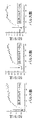
S2とS1として測定されたエネルギーの比の移動を測定することによって、レーザーキャビティ内のエネルギー蓄積が調査された。レーザーによって放射された第1インパルスには、エネルギーの比の求められる増加が観察された(図4)。しかし、この増加はレーザー媒質内の熱的な平衡の確立に基づくものである可能性がある。この熱的な平衡に達していることを確認するためには、数秒間待って、次に、キャビティAの底部ミラーを僅かに回転させることによって、レーザーの放射波長を迅速に変化させる。先に書き込まれた格子は、もはやレーザーの新しい機能モードに適応していないので無効である。新しい格子の形成と先行する格子の消失に連れて、S1からS2へエネルギーの漸進的な移動が生じる。この実験は、レーザーの調整可能性が保存されていることをも示す。1mJ、2mJ、3mJの定常状態における出力エネルギーについて実験が繰り返された。
【0047】
図4において、矢印はレーザーの波長を変更した瞬間を示す。
【0048】
3つの曲線上にS2/S1比の増大が確かめられる。定常状態における種々の出力エネルギーの各々について比が1.96、2、及び1.86に等しいことが分かる。熱的な影響を酌量しなければ、構成要素は有効であり、構成要素の反射率は定常状態に達するための時間と共に増大することが暗示される。初期状態と定常状態の間のこの比の変化から、これらの条件下で、且つ、ブラッグと一致の波長では、構成要素の反射率は60%から75%に移り、光誘導された格子は定常状態において7.5%の反射率を有することが示される。約7mJの結晶上エネルギーと約2mmのビーム径における、光屈折性格子の書き込み時間との一致を得ると、効果は10パルスで確立される。
【0049】
構成要素の効率のエネルギー上の安定性は、定常状態が達成された後でのS2/S1比の50パルスにおける記録によって立証された。10分間の作動の後で、測定が再開された。図5においてS2/S1比が±3%以内で変わっていないことが分かる。
【0050】
図3に示される2本のアーム間のステップ差Δを変動させたマイケルソン干渉計によって、このエネルギー移動にはソースのコヒーレンス長の増大が伴うことが確かめられる。レーザーキャビティに光屈折性結晶が無ければ、スペクトル幅の約0.7nmと一致して、コヒーレンス長は約1mmである。レーザーキャビティに出力鏡から1mmの距離で光屈折性結晶を配置すると、60cmを超えるコヒーレンス長が測定された。互いに異なるステップがΔ=0およびΔ=62cmにおける、光屈折性結晶を用いた作動に対応した干渉図形が図6に再現されている。もしも、マイケルソン干渉計をミリメートル(mm)を優に超えるステップ差Δにて調整し、同様にレーザーの放射波長を僅かに変化させれば、干渉図形の縞(空気コーナーの縞)は消失する(光誘導された格子と出力鏡の装置は不適応である)。この縞は1から2秒後に再出現する(適合した光誘導された新たな格子が構成される)。このプロセスの動力学は以前に測定されたエネルギー蓄積時間定数と一致する。この測定によって、レーザーの線幅が300GHzから1GHz以下に減少したことが確認できる。
【0051】
厚さが3mmのファブリ・ペロー干渉計を用いてスペクトルの微細化を観察することができ(自由スペクトルの間隔50GHz)、スペクトルの微細化はリングの数の減少によって視覚化できる。一つの同じイメージ上に、レーザーキャビティ内に光屈折性結晶無しで得られた干渉図形(左側)と、光屈折性結晶が出力鏡から1mmの位置に置かれた場合に得られた干渉図形(右側)が並記されている。スペクトルの微細化が明白に示されている。この結果は、この線がGHzのオーダーの幅にて得られたことを裏付ける。
【0052】
これらのリングの構造を解明できる可能性のある1GHz未満の解像力のために、ファブリ・ペロー干渉計のミラーが6.6cmまで離間された(自由スペクトルの間隔2.5GHz)。光屈折性結晶と後方ミラーの間の距離dが1mmと8cmの範囲では、長手方向のバイモード(bimode)挙動が観察された。図8は、6.6cmのファブリ・ペロー干渉計にて、距離d=4cmについて得られた干渉図形を示し、レーザーのバイモード作用を図示している。
【0053】
予測されたように、提案された本発明は、レーザーのスペクトル幅を縮小する。さらに、本発明は微妙な調整を必要としない。結晶と出力鏡のアセンブリがその反射率の増大をするように、単純に光屈折性結晶を概略配置するだけで良い。
【0054】
本発明による装置は、通常の調整可能な装置のものに匹敵する正確さを有するが、さらにこの装置に意義を授ける自己適応性の特性を有する。波長が調整可能な光源の場合、本装置の意義は大きい。通常の装置(リオのフィルタ、プリズム、...)による波長の調整は、本発明によって実効可能である。選択された波長に関わらず、線幅はこの装置によって自動的に縮小される。このためには、波長が十分に大きい周波数帯で材料が光屈折性であれば十分である。
【0055】
増幅媒体の他にキャビティ内要素が無ければ、レーザーの放射は一般にマルチモードである。レーザー放射をスペクトル的に微細化するために、複屈折フィルタまたはプリズムと連結されたファブリ・ペロー干渉計が使われる。これらの装置は使用方法が複雑であり、自己適応性はない。
【0056】
分光学の研究のためには、研究したいエネルギー水準の幅を下回るスペクトル幅の放射を用意する必要がある。調整可能な全てのレーザー光源がスペクトルの微細化のオプションと共に提案されているのはこのためである。このようなスペクトルの縮小化は本発明によって実現できる。
【0057】
長いコヒーレンス長(干渉測定)或いはスペクトルの微小幅(流速測定)を必要とする研究では、通常は非常に大きく固定された使用されるレーザーの輝線を微細化することが強いられる。例えば、パルス型Nd:YAGのレーザーの場合、モノモードの連続したNd:YAGの第2レーザーが用いられる。モノモードの第2レーザーはいわゆる「マスター」であり、いわゆる「スレーブ」のパルスレーザーの放射にモノモード状態を強制するための射出機(インジェクタ)として働く。ここに示された本発明は、この複雑で実施にコストの掛かる解決法に対して有利に取って代わる。
【0058】
この問題はOPOの場合に特に著しい。それらの輝線は、実際のところ、特に射出がなされない場合、そして、特に縮退の近傍で作用する場合、幅が数ナノメートルのスペクトル領域を有する。この場合、実際に一致の条件は大きい。そのような光源は、微細化されることが有利である。スペクトルの微細化は一般に回折格子の助力を介して得られ、この回折格子は自己適応性フィルタによって置き換えることができる。
【0059】
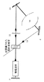
可能性のある3番目の幾何学形状が図9に示されている。共振キャビティはミラー31とカプラー22で構成されている。このキャビティ外に配置されたミラー3及び4は、放射されたビームが光屈折性材料上に届けられるのを許す。このビームは、ホログラムを書き込むために、共振キャビティ内に存在するビームと干渉する。このホログラムはビーム35に由来する光を主キャビティに再射出する。補足的な濾波あるいは波長または空間モードの選択を確実にするために、ミラーと光屈折性材料で形成されたキャビティ内に空間的フィルタまたはスペクトル的フィルタが挿入されると有利である。
【0060】
本発明の範囲内でマルチモードのマイクロレーザーをモノモード化することも可能である。
【0061】
そして、スペクトルの幅を縮小させながら、出力用レーザーダイオードの空間的特性を改善することが完璧に可能である。
【0062】
適用は特に、連続状態での放射用の電気通信の分野における、モードのジャンプを回避したモノモードの光源の実現に関する。
【図面の簡単な説明】
【図1】 第1のバリエーションの略図である。
【図2】 第2のバリエーションの略図である。
【図3】 本発明による装置を含む設備の接続の略図である。
【図4】 定常状態で出力エネルギーが種々異なる場合のキャビティ内エネルギーとレーザー出力エネルギーの間の関係の時間による推移を示す図である。
【図5】 定常状態の直後(左側の曲線)及び10分間の作動後(右側の曲線)におけるS2/S1比のエネルギーの安定曲線を示す図である。
【図6】 2つの異なる行程における空気くさびの縞を示す図である。
【図7】 光屈折性結晶がある場合と無い場合において得られる干渉図形である。
【図8】 レーザーの2つのモードを明白化させる干渉図形である。
【図9】 第3のバリエーションの略図である。[0001]
The present invention relates to a laser-type coherence light source. The present invention more specifically relates to a reduction in the number of modes in the longitudinal and / or transverse direction of the radiation source (spectral refinement and / or spatial refinement).
[0002]
In order to reduce the width of the laser emission line, selective elements that require some kind of adjustment have been proposed in the prior art, such as the Lyot filter and the Fabry-Perot filter. .
[0003]
There are several spectral refiners that have been published or patented. For example, in the prior art, European patent EP 284908 is known which describes a device for controlling or adjusting the wavelength λe emitted from a semiconductor laser and the output of light. The output of the light emitted by the laser is sent at least in part to a photoelectric detector and at least one optical filter device that is selective with respect to wavelength. Part of the output sent to this optical filter device is transmitted to another photoelectric detection device. According to this state of the art, the semiconductor laser, the filter device and the detector are integrated on a common base. The integrated filter device may be a Bragg grating, or by a directional coupler or interference filter, or two or more Bragg gratings placed one after the other in the direction of propagation of the transmitted power, and / or Alternatively, it is constituted by an assembly formed by a directional optical coupler and / or an interference filter.
[0004]
In the prior art, the laser cavity A wavelength-selective but not self-adaptive device arranged in the (oscillator) has been proposed. Electron.Lett.27, 183 (1991) "82 nm of continuous tunability for an external cavity semiconductor laser" Article describes the process of miniaturization and stabilization of a diode laser in a stretchable cavity using a conventional diffraction grating. Diffraction grating is stretchable cavity Is an element of wavelength selection. Two factors contributing to miniaturization are the extension type that reduces the dispersion of the lattice and the width of the Shalow-Townes of the synchrotron radiation. cavity Is the length of
[0005]
DFB (feedback distribution) type with integrated Bragg grating in the active area, or Bragg grating cavity A DBR (Bragg reflector distribution) type diode laser integrated as a mirror is also known. These Bragg mirrors are not self-adaptive.
[0006]
Among the prior art, external cavity Various solutions are known for the stabilization of the laser spectrum according to. US Pat. No. 4,907,237 discloses an external device with a special resonance frequency. cavity Describes a method for stabilizing a diode laser. Outside cavity Part of the output beam of the laser cavity It is reincident inside.
[0007]
Also, among the prior art, external systems for self-adaptive miniaturization are known. Appl. Phys. B65, 329 (1997) “BaTiO3: Co-stimulated photorefractive back-dispersed phase fused AlGaInP diode laser wavelength-stable narrow spectrum oscillation” joined by reflection. A phase fusion mirror using the wavelength selectivity of the Bragg grating is used, and a part of the beam is a laser beam. cavity The laser beam re-entered inside is described. This device cavity With crystals arranged outside. Therefore, the phase relationship is fixed.
[0008]
Also annular cavity Japanese Patent No. EP 433122 describing a type of laser device is also known. This relates to the incidence of light from the main laser to a slave laser with the same interference characteristics as the main laser. Since there is no return from the slave laser to the main laser, the presence of the photosensitive material does not change the spectral characteristics of the main laser.
[0009]
Article “Reduction of laser frequency bandwidth by light-reflective two-beam coupling” published in Opt. Lett. 17, 481, (1992) cavity Describes the filtering of the beam frequency emitted from a laser by a light-reflecting grating created by the beam emitted from the laser.
[0010]
Literature, OPTICS LETTERS, Vol. 12, No. 2, February 1, 1987, 117-119, author Whitten et al. cavity `` Mode selection in continuous wave dye laser with inner photosensitive element '' is a linear resonance cavity And this resonance cavity Resonance to form self-adaptive spectral and / or spatial filters in addition to the amplification medium disposed within cavity A dynamic photosensitive material disposed within Radiation source It is about.
[0011]
Prior art devices have various disadvantages. For example, length change due to temperature fluctuation cavity When the characteristics of the interference filter fluctuate, the effect of the interference filter proposed by a certain device of the prior art decreases.
[0012]
Solutions using external means often require delicate adjustments and are sensitive to mechanical stress.
[0013]
In order to eliminate these inconveniences, the present invention, in the most general sense, is a resonance in which an amplification medium is arranged. cavity (Laser, optical parametric oscillator, also called OPO,...) Related to a coherence light source formed in a dynamic photosensitive material cavity It is characterized in that it forms a self-adaptive spectral filter and / or a spatial filter with the other elements in it.
[0014]
Accordingly, the present invention provides self-adaptive and stable spectral and / or spatial refinement within a coherence light source. cavity It features a built-in optical device.
[0015]
The present invention cavity Is based on writing a grating in a dynamic light-sensitive material with a wave structure. Selected accordingly cavity The wavelength selectivity of this grating associated with one or more of the mirrors realizes an automatically adapted filter, and therefore, using the competition between multiple modes, the existing possibility of wavelength change Can be maintained while improving the temporal and spatial coherence of the emitted light.
[0016]
This filter is in each possible mode cavity Automatically modulates losses in various ways, cavity To vibrate only in a single or a few modes. Adaptation is cavity This is carried out through the writing of a grating or hologram into the dynamic photosensitive material with a vibrating beam of. This adaptation allows interfering gratings (spatial changes in light intensity or Of the polarization state of light A unique response of the selected dynamic light-sensitive material that reacts only to (change). More preferably, the dynamic photosensitive material is composed of a photorefractive material. These materials are used for lighting gradients Sensitive .
[0017]
Other materials are also suitable where the change in refractive index, absorption, or anisotropy is based on, for example, the movement of a substance. In this type of reaction, writing a hologram adapted to one mode erases a hologram written by another mode.
[0018]
According to another preferred variation, the dynamic photosensitive material is characterized by illumination characteristics (intensity or Polarization ) Sensitive to spatial changes. According to one special embodiment, the dynamic photosensitive material is formed by a plurality of thin films and resonant. cavity Placed within, forms a self-adaptive spectral and / or spatial filter.
[0019]
According to the first embodiment implemented, cavity Is linear cavity The dynamic photosensitive material is formed of a photorefractive material that functions in a diffused state. In the cavity The Fabry-Perot interferometer, which exhibits maximum reflectivity in the hologram writing mode, is formed in cooperation with the output mirror. cavity Is linear cavity The dynamic photosensitive material is Inductive permeability Advantageously, it is a suitably arranged material having
[0020]
According to a second embodiment to be implemented, cavity Is an annular laser cavity The dynamic photosensitive material is arranged at the intersection of two intersecting beams. According to one embodiment, the dynamic photorefractive material comprises a barium titanate crystal.
[0021]
The main advantage of the present invention is that no adjustment is required and the action is self-adaptive. The proposed invention advantageously avoids the use of a Fabry-Perot interferometer to select wavelength refinement. The present invention is applicable to a number of lasers, including continuous diode lasers and microlasers, as well as impulsiveness for all wavelengths, where: sensitivity Depending on the fineness of the light flux and other properties required for the function of the device, a suitable dynamic photosensitive material will be found.
[0022]
The invention will be better understood by reading the following description with reference to the accompanying drawings, in which:
[0023]
The device is light for the wavelength used Photosensitivity The material is constructed around a dynamic material (1). In order to ensure selective self-adaptability for one specific mode, this material is characterized by the form of illumination (intensity, local Polarization . . . Only for spatial changes) reaction To its uniform composition reaction should not be done. This is the case typical of materials where the change in refractive index or absorption is a function of the ratio of the modulation mi of the interference form that the material is mainly illuminated.
mi = Ii / (Ii + ΣIi)
[0024]
The intensity Ii of mode i as well as the diffraction efficiency of the accompanying hologram or grating increases with mi. This reduces the other modulation ratio mj as well as the diffraction efficiency of the accompanying hologram.
[0025]
light Photosensitivity The dynamic material is the center of the device, and its adaptation to one mode i (i is a number) or a few multiple modes reacts to increase the ratio:
R = loss in any other mode / loss in that mode i
[0026]
Depending on the ratio, the loss in this mode may decrease more than in other modes, or the loss in this mode may not change and increase in all other modes.
[0027]
Loss reduction in this mode and / or increase in loss in all other modes Photosensitivity This light of sexual dynamic material Photosensitivity Dynamic materials and mirrors etc. cavity Is defined by the position in the apparatus consisting of the normal optical configuration.
[0028]
Several classes of light Photosensitivity Dynamic material fits, for example
・ Photorefractive material, or
A material whose hologram writing is the result of redistribution of absorption centers. Some other light that is associated with charge redistribution from mass transfer in the gradient of illumination, or absorption and refractive index changes, if in other materials Photosensitivity It is possible to cite the change in absorption observed in the crystal. These materials are It may be formed thin or thick. Moreover, it may be formed from a single material and may have a configuration. . As the thickness increases, it can be advantageously used to enhance the selectivity of the self-adaptive filter. In the case of thin materials, it is possible to enhance the selectivity as well with several samples separated from each other.
[0029]
Various devices can be envisaged for the type of hologram to be written (absorption or refractive index). Similarly, cavity Various structures can be realized according to the geometrical shape (linear, annular ...). Let us cite the following device as an example.
[0030]
As a photorefractive material used in the diffuse state, the induced hologram is a refractive index hologram having a quarter phase difference with respect to the illumination form.
[0031]
The geometric shape shown in FIG. cavity The level of technology using The device is shown in a shaded rectangle. This device comprises a photorefractive material (1) and cavity Output mirror (2). cavity The grating written in the photorefractive material by the standing wave constitutes a Bragg mirror. By accompanying the output mirror (2), a Fabry-Perot filter suitable for a mode in which a grating or a hologram is written is formed. The photorefractive material is positioned such that the discrepancy orientation between the illumination and refractive index gratings gives the Fabry-Perot filter maximum reflectivity in the mode in which the hologram is written. The reflectivity of the device increases for this mode, thus reducing losses and promoting vibration. The selectivity introduced is a function of the distance between the material and the mirror and the thickness of the material.
[0032]
The mirror is preferably affixed to the amplifying medium to form a microlaser as a whole.
[0033]
The material is inserted between the amplification medium (3) and the output mirror (2). cavity The hologram written by the standing wave corresponding to this mode is a Bragg mirror that partially reflects each of two opposing propagating waves. In the example described, the holographic material (1) is constituted by a photorefractive crystal of barium titanate.
[0034]
The response of the device, linked to the response of a laser amplifying medium with a uniform line, causes competition between modes and the laser cavity To vibrate only in a single mode or a few modes.
[0035]
For laser amplification media with non-uniform lines, the losses induced in other modes are cavity It is necessary to be large enough to fall below the vibration threshold of the laser, and thus the laser radiation is spectrally and / or spatially refined.
[0036]
Here, self-adaptability is achieved by writing a hologram induced by one or more modes of a laser in the center of a suitable dynamic photosensitive material.
[0037]
laser cavity A variation when is circular is shown in the schematic of FIG. The device in the shaded rectangle is made up of the material and two mirrors that are the output mirrors. The grating or hologram is similar to the previous example, cavity Written by interference present in the
[0038]
The grating is written by all waves that interfere in the photorefractive material. This photorefractive material is arranged so that the reflectivity of the device increases with respect to the mode in which the hologram was written. In some cases, the device also functions as a photodiode (the laser oscillates in only one direction).
[0039]
Inductive permeability For holograms, the device is a dynamic photosensitive material and cavity It is constituted by one of a plurality of mirrors. The two beams propagating oppositely are in phase with the illumination form Permeability This reduces the loss in this mode. In steady state, the absorption center is preferably inside dark stripes in the enhanced mode of illumination, which in turn increases the loss in other modes.
[0040]
FIG. 3 shows a schematic diagram of the connection of equipment with a device according to the invention and a control system that can ensure the function of this device. The laser is a titanium-doped sapphire laser pumped at 10 Hz by a Nd: YAG laser with a frequency multiplied by nanoseconds. This laser emits an impulse of 50 ns in length when activated by gain. Laser tunability is realized by two adjustable prisms. cavity Since there is no Fabry-Perot filter, the obtained spectrum extends to about 0.7 nm. Line uniformity allows competition between modes. Original laser on the market cavity Has a length of 60 cm. The output mirror (mirror B) has a reflectivity of 60% and transmits the output S0.
[0041]
The dynamic photosensitive material (1) is arranged at a distance that can be changed between 1 mm and several centimeters from the output mirror (B) due to the space available in this special laser. In one variation of implementation, the configuration mirror (B) may be placed on the crystal. For the radiation wavelength of this laser, a cobalt-doped barium titanate photorefractive crystal cut at 45 ° from the optical axis was selected from the available materials, which is 0.2 cm. -1 The absorption is about 750 nm and has a thickness of 2 mm. This makes it possible to eliminate the problem of optical inconvenience by taking advantage of the maximum gain (about 780 nm) of a sapphire crystal laser doped with titanium. This forms an effective wavelength of 760 nm.
[0042]
In order to test the functionality of the device according to the invention, three systems were installed.
[0043]
The glass sheet LS2 arranged in front of the plurality of prisms extracts a part of the intracavity beam (output S2). The second thin plate LS1 extracts a part of the beam as an output S0 (signal S1). Fast diodes P1 and P2 for outputs S1 and S2 are lasers due to increased reflectivity due to self-adaptive filters. cavity Makes it possible to observe the accumulation of energy within.
[0044]
A planar Fabry-Perot interferometer makes it possible to visualize the interference ring. Therefore, it is possible to observe the refinement of the laser spectrum.
[0045]
A Michelson interferometer makes it possible to evaluate the length of commissibility of the laser source.
[0046]
By measuring the shift in the ratio of the energy measured as S2 and S1, the laser cavity The energy storage within was investigated. In the first impulse emitted by the laser, the required increase in the energy ratio was observed (FIG. 4). However, this increase may be based on the establishment of thermal equilibrium in the laser medium. To confirm that this thermal equilibrium has been reached, wait a few seconds, then cavity By slightly rotating the bottom mirror of A, the emission wavelength of the laser is rapidly changed. The previously written grating is invalid because it is no longer adapted to the new functional mode of the laser. As the new lattice forms and the preceding lattice disappears, a gradual transfer of energy occurs from S1 to S2. This experiment also shows that laser tunability is preserved. The experiment was repeated for output energy at steady state of 1 mJ, 2 mJ, 3 mJ.
[0047]
In FIG. 4, the arrow indicates the moment when the wavelength of the laser is changed.
[0048]
An increase in the S2 / S1 ratio is confirmed on the three curves. It can be seen that the ratio is equal to 1.96, 2, and 1.86 for each of the various output energies in steady state. If the thermal effect is not neglected, it is implied that the component is effective and the reflectivity of the component increases with time to reach steady state. From this change in ratio between the initial and steady state, under these conditions and at wavelengths consistent with Bragg, the reflectivity of the component shifts from 60% to 75%, and the light-induced grating is stationary. It is shown to have a reflectivity of 7.5% in the state. The effect is established with 10 pulses when a match is made with the photorefractive grating writing time at about 7 mJ energy on the crystal and about 2 mm beam diameter.
[0049]
The energy stability of the component efficiency was verified by recording the S2 / S1 ratio at 50 pulses after steady state was achieved. After 10 minutes of operation, the measurement was resumed. In FIG. 5, it can be seen that the S2 / S1 ratio does not change within ± 3%.
[0050]
A Michelson interferometer with varying step difference Δ between the two arms shown in FIG. 3 confirms that this energy transfer is accompanied by an increase in the source coherence length. laser cavity If there is no photorefractive crystal, the coherence length is about 1 mm, corresponding to a spectral width of about 0.7 nm. laser cavity When a photorefractive crystal was placed at a distance of 1 mm from the output mirror, a coherence length exceeding 60 cm was measured. The interferogram corresponding to the operation using the photorefractive crystal with different steps Δ = 0 and Δ = 62 cm is reproduced in FIG. If the Michelson interferometer is adjusted with a step difference Δ well in excess of millimeters (mm), and the laser emission wavelength is slightly changed, the interference pattern stripes (air corner stripes) disappear. (The light-guided grating and output mirror devices are inadequate). This fringe reappears after 1 to 2 seconds (a new light-guided lattice adapted is constructed). The kinetics of this process is consistent with the previously measured energy storage time constant. This measurement confirms that the line width of the laser has decreased from 300 GHz to 1 GHz or less.
[0051]
Spectral refinement can be observed using a Fabry-Perot interferometer with a thickness of 3 mm (free spectral spacing 50 GHz), which can be visualized by reducing the number of rings. Laser on one and the same image cavity The interference pattern (left side) obtained without the photorefractive crystal is shown in parallel with the interference pattern (right side) obtained when the photorefractive crystal is placed at a
[0052]
The Fabry-Perot interferometer mirrors were separated to 6.6 cm (free spectral spacing 2.5 GHz) due to the sub-1 GHz resolution that could potentially elucidate the structure of these rings. Bimode behavior in the longitudinal direction was observed when the distance d between the photorefractive crystal and the rear mirror was in the range of 1 mm and 8 cm. FIG. 8 shows the interferogram obtained for a distance d = 4 cm in a 6.6 cm Fabry-Perot interferometer, illustrating the bimodal action of the laser.
[0053]
As expected, the proposed invention reduces the spectral width of the laser. Furthermore, the present invention does not require subtle adjustments. Simply place the photorefractive crystal roughly so that the crystal and output mirror assembly increases its reflectivity.
[0054]
The device according to the present invention has an accuracy comparable to that of a normal adjustable device, but also has a self-adaptive property that makes the device meaningful. In the case of a light source whose wavelength can be adjusted, the significance of this apparatus is great. Tuning the wavelength with conventional equipment (Rio filters, prisms, ...) is possible with the present invention. Regardless of the wavelength selected, the line width is automatically reduced by this device. For this purpose, it is sufficient if the material is photorefractive in a sufficiently large wavelength band.
[0055]
Besides amplification media cavity Without the inner element, laser radiation is generally multimode. A Fabry-Perot interferometer coupled with a birefringent filter or prism is used to spectrally refine the laser radiation. These devices are complicated to use and are not self-adapting.
[0056]
For spectroscopic studies, it is necessary to provide radiation with a spectral width below the range of energy levels that we wish to study. This is why all tunable laser sources have been proposed with the option of spectral refinement. Such spectrum reduction can be realized by the present invention.
[0057]
In studies that require a long coherence length (interferometry) or a small spectral width (flow velocity measurement), it is usually forced to refine the emission line of the laser used, which is very large and fixed. For example, in the case of a pulsed Nd: YAG laser, a monomode continuous Nd: YAG second laser is used. The mono-mode second laser is a so-called “master” and acts as an injector for forcing the mono-mode state on the radiation of a so-called “slave” pulse laser. The present invention shown here advantageously replaces this complex and costly solution.
[0058]
This problem is particularly significant in the case of OPO. These emission lines actually have a spectral region with a width of a few nanometers, especially when no emission is made, and especially when acting in the vicinity of degeneracy. In this case, the matching condition is actually large. Such light sources are advantageously miniaturized. Spectral refinement is generally obtained through the aid of a diffraction grating, which can be replaced by a self-adaptive filter.
[0059]
A possible third geometry is shown in FIG. resonance cavity Consists of a
[0060]
It is also possible to convert the multimode microlaser into a monomode within the scope of the present invention.
[0061]
It is perfectly possible to improve the spatial characteristics of the output laser diode while reducing the width of the spectrum.
[0062]
The application relates in particular to the realization of monomode light sources avoiding mode jumps in the field of telecommunications for radiation in a continuous state.
[Brief description of the drawings]
FIG. 1 is a schematic diagram of a first variation.
FIG. 2 is a schematic diagram of a second variation.
FIG. 3 is a schematic representation of the connection of equipment including a device according to the invention.
FIG. 4 shows the case where the output energy varies in a steady state. cavity It is a figure which shows transition by the time of the relationship between internal energy and laser output energy.
FIG. 5 is a diagram showing an energy stability curve of the S2 / S1 ratio immediately after a steady state (left curve) and after 10 minutes of operation (right curve).
FIG. 6 shows air wedge stripes in two different strokes.
FIG. 7 is an interference pattern obtained with and without a photorefractive crystal.
FIG. 8 is an interferogram that clarifies the two modes of the laser.
FIG. 9 is a schematic diagram of a third variation.
Claims (9)
前記共振キャビティ内に配置された増幅媒体(3)と、
前記共振キャビティ内を対向伝搬する2つのビームの交点に配された、ダイナミック感光部材(1)と、を備え、
前記共振キャビティ内における前記ビームの光路は環状に形成されおり、
前記ダイナミック感光部材(1)に照射される光によって、当該ダイナミック感光部材(1)に格子またはホログラムを書き込み、これにより自己適応型のスペクトルフィルタ又は空間フィルタを形成すること特徴とするレーザータイプのコヒーレンス光放射源。 A resonant cavity;
An amplification medium (3) disposed in the resonant cavity;
A dynamic photosensitive member (1) disposed at the intersection of two beams that propagate oppositely in the resonant cavity;
The optical path of the beam in the resonant cavity is formed in an annular shape ,
A laser-type coherence is characterized in that a grating or hologram is written on the dynamic photosensitive member (1) by the light applied to the dynamic photosensitive member (1), thereby forming a self-adaptive spectral filter or spatial filter. Light radiation source.
Applications Claiming Priority (3)
| Application Number | Priority Date | Filing Date | Title |
|---|---|---|---|
| FR98/13525 | 1998-10-28 | ||
| FR9813525A FR2785459B1 (en) | 1998-10-28 | 1998-10-28 | SELF-ADAPTED FILTERS FOR REFINING THE LASER EMISSION |
| PCT/FR1999/002644 WO2000025396A1 (en) | 1998-10-28 | 1999-10-28 | Self-adapted filters for sharpening laser emission |
Publications (3)
| Publication Number | Publication Date |
|---|---|
| JP2002528919A JP2002528919A (en) | 2002-09-03 |
| JP2002528919A5 JP2002528919A5 (en) | 2009-07-30 |
| JP4372354B2 true JP4372354B2 (en) | 2009-11-25 |
Family
ID=9532094
Family Applications (1)
| Application Number | Title | Priority Date | Filing Date |
|---|---|---|---|
| JP2000578881A Expired - Fee Related JP4372354B2 (en) | 1998-10-28 | 1999-10-28 | Self-adaptive filter for laser emission miniaturization. |
Country Status (7)
| Country | Link |
|---|---|
| US (1) | US6674782B2 (en) |
| EP (1) | EP1125347B1 (en) |
| JP (1) | JP4372354B2 (en) |
| CA (1) | CA2347995A1 (en) |
| DE (1) | DE69905188T2 (en) |
| FR (1) | FR2785459B1 (en) |
| WO (1) | WO2000025396A1 (en) |
Families Citing this family (13)
| Publication number | Priority date | Publication date | Assignee | Title |
|---|---|---|---|---|
| FR2815182B1 (en) * | 2000-10-10 | 2003-02-28 | Photonetics | CONTINUOUSLY TUNABLE WAVELENGTH SINGLE-MODE LASER SOURCE |
| EP1481454B1 (en) | 2002-03-04 | 2010-06-30 | Danmarks Tekniske Universitet | High-power diode laser system |
| US7046374B1 (en) * | 2002-03-14 | 2006-05-16 | Avanex Corporation | Interferometers for optical communications utilizing photo-sensitive materials |
| FR2860291B1 (en) * | 2003-09-26 | 2005-11-18 | Thales Sa | OPTICAL FIBER INTERFEROMETRIC ROTATION SPEED SENSOR DEVICE |
| FR2869162B1 (en) * | 2004-04-14 | 2006-07-14 | Centre Nat Rech Scient Cnrse | TUNABLE LASER SOURCE WITH OPTICAL WAVELENGTH ADDRESSING |
| FR2892239B1 (en) * | 2005-10-13 | 2008-01-04 | Centre Nat Rech Scient | OPTICAL DEVICE FOR ADDRESSING SLAVE CAVITY BY A BROADBAND SOURCE |
| GB0612348D0 (en) * | 2006-06-21 | 2006-08-02 | Imp Innovations Ltd | Method and apparatus for coherently combining laser emission |
| FR2935845B1 (en) | 2008-09-05 | 2010-09-10 | Centre Nat Rech Scient | FABRY-PEROT AMPLIFIER OPTICAL CAVITY |
| KR101031087B1 (en) * | 2009-07-23 | 2011-04-25 | 주식회사 와이텔포토닉스 | Tunable fiber laser system |
| FR2954637B1 (en) * | 2009-12-21 | 2014-07-18 | Alcatel Lucent | METHOD FOR RECEIVING A SIGNAL |
| RU2572659C2 (en) * | 2011-06-09 | 2016-01-20 | Общество с ограниченной ответственностью "Научно-производственное предприятие "Лазерные системы" | Laser system with multi-loop resonator |
| JP5474891B2 (en) * | 2011-08-12 | 2014-04-16 | ギガフォトン株式会社 | Light source device and exposure apparatus using the same |
| CN103516434B (en) * | 2012-06-19 | 2016-08-31 | 上海贝尔股份有限公司 | Optical sender |
Family Cites Families (8)
| Publication number | Priority date | Publication date | Assignee | Title |
|---|---|---|---|---|
| IL74284A (en) * | 1985-02-08 | 1989-02-28 | Technion Res & Dev Foundation | Optical apparatus particularly useful as an optical gyro |
| US5037203A (en) * | 1985-10-10 | 1991-08-06 | Rockwell International Corporation | Asymmetric ring laser gyroscope and method for detecting rotation with acentric photorefractive crystal |
| US4869579A (en) * | 1986-07-31 | 1989-09-26 | Technion Research & Development Foundation | Optical apparatus and method for beam coupling useful in light beam steering and spatial light modulation |
| US4911537A (en) * | 1988-08-05 | 1990-03-27 | Rockwell International Corporation | Bird-wing phase conjugator using mutually incoherent laser beams |
| FR2655485B1 (en) * | 1989-12-01 | 1992-02-21 | Thomson Csf | RING CAVITY LASER DEVICE. |
| US5073705A (en) * | 1990-04-06 | 1991-12-17 | The United States Of America As Represented By The Secretary Of The Army | Broadband, multi-line, optical power limiting scheme |
| US6274288B1 (en) * | 1995-06-12 | 2001-08-14 | California Institute Of Technology | Self-trapping and self-focusing of optical beams in photopolymers |
| US5665493A (en) * | 1995-10-03 | 1997-09-09 | Sri International | Gated recording of holograms using rare-earth doped ferroelectric materials |
-
1998
- 1998-10-28 FR FR9813525A patent/FR2785459B1/en not_active Expired - Fee Related
-
1999
- 1999-10-28 CA CA002347995A patent/CA2347995A1/en not_active Abandoned
- 1999-10-28 DE DE69905188T patent/DE69905188T2/en not_active Expired - Lifetime
- 1999-10-28 EP EP99950876A patent/EP1125347B1/en not_active Expired - Lifetime
- 1999-10-28 JP JP2000578881A patent/JP4372354B2/en not_active Expired - Fee Related
- 1999-10-28 WO PCT/FR1999/002644 patent/WO2000025396A1/en active IP Right Grant
-
2001
- 2001-04-25 US US09/841,723 patent/US6674782B2/en not_active Expired - Fee Related
Also Published As
| Publication number | Publication date |
|---|---|
| FR2785459A1 (en) | 2000-05-05 |
| WO2000025396A1 (en) | 2000-05-04 |
| DE69905188T2 (en) | 2003-10-09 |
| FR2785459B1 (en) | 2001-05-04 |
| US20020006150A1 (en) | 2002-01-17 |
| EP1125347B1 (en) | 2003-01-29 |
| JP2002528919A (en) | 2002-09-03 |
| EP1125347A1 (en) | 2001-08-22 |
| CA2347995A1 (en) | 2000-05-04 |
| US6674782B2 (en) | 2004-01-06 |
| DE69905188D1 (en) | 2003-03-06 |
Similar Documents
| Publication | Publication Date | Title |
|---|---|---|
| JP4372354B2 (en) | Self-adaptive filter for laser emission miniaturization. | |
| US9178330B2 (en) | Apparatus and method for utilization of a high-speed optical wavelength tuning source | |
| US20050243884A1 (en) | Laser tuning by spectrally dependent spatial filtering | |
| JPH025490A (en) | Solid state microlaser | |
| JPH09260753A (en) | External resonator-type variable wavelength light source | |
| EP0719467A1 (en) | Wavelength stabilized laser sources using feedback from volume holograms | |
| US5889800A (en) | Broadly tunable single longitudinal mode output produced from multi-longitudinal mode seed source | |
| JP2002503392A (en) | Laser system using phase conjugate feedback | |
| JP2009060022A (en) | Wavelength-scanning light source | |
| US20090225800A1 (en) | Very low-noise semiconductor laser | |
| JP2004511914A (en) | Tunable single mode laser device | |
| CN117293636B (en) | Double-comb middle infrared oscillator | |
| CN112653514B (en) | Multi-wavelength light source generator and method of generating multi-wavelength light source | |
| RU192951U1 (en) | HIGH-BRIGHTNESS SOLID LASER WITH CONTROLLED SPECTRAL PROPERTIES | |
| JPS6345875A (en) | Multimode narrow band oscillation excimer laser | |
| JP2683252B2 (en) | Semiconductor laser frequency stabilizer | |
| JP2009512205A (en) | Optical device for addressing slave cavities with broadband laser sources | |
| Pogoda et al. | Principle of influence of static and dynamic intracavity gratings on spectral properties of high-power all-solid-state laser’s radiation | |
| RU1764485C (en) | Semiconductor laser | |
| CN114424416A (en) | Laser wavelength stabilizing device | |
| JP2931116B2 (en) | Tunable laser device | |
| US20030138022A1 (en) | Method of manufacturing helicoidal mirrors and distributed feedback elements | |
| Anokhov | A laser cavity used as an etalon for interferometric control of its own field | |
| JPH03244176A (en) | Laser device | |
| JPH1168202A (en) | Injection seeding device |
Legal Events
| Date | Code | Title | Description |
|---|---|---|---|
| A621 | Written request for application examination |
Free format text: JAPANESE INTERMEDIATE CODE: A621 Effective date: 20060905 |
|
| A131 | Notification of reasons for refusal |
Free format text: JAPANESE INTERMEDIATE CODE: A131 Effective date: 20081216 |
|
| A601 | Written request for extension of time |
Free format text: JAPANESE INTERMEDIATE CODE: A601 Effective date: 20090313 |
|
| A602 | Written permission of extension of time |
Free format text: JAPANESE INTERMEDIATE CODE: A602 Effective date: 20090323 |
|
| A601 | Written request for extension of time |
Free format text: JAPANESE INTERMEDIATE CODE: A601 Effective date: 20090415 |
|
| A602 | Written permission of extension of time |
Free format text: JAPANESE INTERMEDIATE CODE: A602 Effective date: 20090422 |
|
| A601 | Written request for extension of time |
Free format text: JAPANESE INTERMEDIATE CODE: A601 Effective date: 20090507 |
|
| A602 | Written permission of extension of time |
Free format text: JAPANESE INTERMEDIATE CODE: A602 Effective date: 20090514 |
|
| A524 | Written submission of copy of amendment under article 19 pct |
Free format text: JAPANESE INTERMEDIATE CODE: A524 Effective date: 20090615 |
|
| TRDD | Decision of grant or rejection written | ||
| A01 | Written decision to grant a patent or to grant a registration (utility model) |
Free format text: JAPANESE INTERMEDIATE CODE: A01 Effective date: 20090804 |
|
| A01 | Written decision to grant a patent or to grant a registration (utility model) |
Free format text: JAPANESE INTERMEDIATE CODE: A01 |
|
| A61 | First payment of annual fees (during grant procedure) |
Free format text: JAPANESE INTERMEDIATE CODE: A61 Effective date: 20090902 |
|
| FPAY | Renewal fee payment (event date is renewal date of database) |
Free format text: PAYMENT UNTIL: 20120911 Year of fee payment: 3 |
|
| R150 | Certificate of patent or registration of utility model |
Free format text: JAPANESE INTERMEDIATE CODE: R150 |
|
| LAPS | Cancellation because of no payment of annual fees |