JP4372012B2 - Drug dispensing device - Google Patents
Drug dispensing device Download PDFInfo
- Publication number
- JP4372012B2 JP4372012B2 JP2004544943A JP2004544943A JP4372012B2 JP 4372012 B2 JP4372012 B2 JP 4372012B2 JP 2004544943 A JP2004544943 A JP 2004544943A JP 2004544943 A JP2004544943 A JP 2004544943A JP 4372012 B2 JP4372012 B2 JP 4372012B2
- Authority
- JP
- Japan
- Prior art keywords
- door
- medicine
- closed
- opened
- dispensing device
- Prior art date
- Legal status (The legal status is an assumption and is not a legal conclusion. Google has not performed a legal analysis and makes no representation as to the accuracy of the status listed.)
- Expired - Fee Related
Links
Images


Classifications
-
- B—PERFORMING OPERATIONS; TRANSPORTING
- B65—CONVEYING; PACKING; STORING; HANDLING THIN OR FILAMENTARY MATERIAL
- B65B—MACHINES, APPARATUS OR DEVICES FOR, OR METHODS OF, PACKAGING ARTICLES OR MATERIALS; UNPACKING
- B65B35/00—Supplying, feeding, arranging or orientating articles to be packaged
- B65B35/10—Feeding, e.g. conveying, single articles
- B65B35/20—Feeding, e.g. conveying, single articles by reciprocating or oscillatory pushers
-
- B—PERFORMING OPERATIONS; TRANSPORTING
- B65—CONVEYING; PACKING; STORING; HANDLING THIN OR FILAMENTARY MATERIAL
- B65G—TRANSPORT OR STORAGE DEVICES, e.g. CONVEYORS FOR LOADING OR TIPPING, SHOP CONVEYOR SYSTEMS OR PNEUMATIC TUBE CONVEYORS
- B65G59/00—De-stacking of articles
- B65G59/06—De-stacking from the bottom of the stack
-
- B—PERFORMING OPERATIONS; TRANSPORTING
- B65—CONVEYING; PACKING; STORING; HANDLING THIN OR FILAMENTARY MATERIAL
- B65B—MACHINES, APPARATUS OR DEVICES FOR, OR METHODS OF, PACKAGING ARTICLES OR MATERIALS; UNPACKING
- B65B5/00—Packaging individual articles in containers or receptacles, e.g. bags, sacks, boxes, cartons, cans, jars
- B65B5/08—Packaging groups of articles, the articles being individually gripped or guided for transfer to the containers or receptacles
-
- G—PHYSICS
- G07—CHECKING-DEVICES
- G07F—COIN-FREED OR LIKE APPARATUS
- G07F17/00—Coin-freed apparatus for hiring articles; Coin-freed facilities or services
- G07F17/0092—Coin-freed apparatus for hiring articles; Coin-freed facilities or services for assembling and dispensing of pharmaceutical articles
Description
本発明は薬剤払出装置に関する。 The present invention relates to a medicine dispensing device.
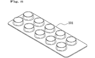
従来、図7に示すブリスターパック100や、図8に示すヒート錠剤101、図9に示す特殊アンプル102のような包装された薬剤を、薬剤師の要求に応じて払い出す薬剤払出装置では、薬剤ケースに複数の薬剤を上下方向に積載し、最下段のものから水平方向に押し出して払い出すようになっている(特許文献はなし)。
Conventionally, in a medicine dispensing device that dispenses a packaged medicine such as the
この種の薬剤払出装置では、薬剤が欠品すると、薬剤ケースに薬剤を積載して充填するが、このとき薬剤の端面が上下方向に整列せずに前後方向にずれていると、最下段の薬剤を水平方向に押し出す押出し機構が正常に動作しない場合がある。このため、薬剤の充填時には、薬剤の後端面が面一に整列するように揃える必要があり、充填作業が煩雑になっていた。 In this type of medicine dispensing device, when a medicine is missing, the medicine case is loaded and filled with the medicine. At this time, if the end faces of the medicine are not aligned in the vertical direction and are displaced in the front-rear direction, An extrusion mechanism that extrudes a medicine in a horizontal direction may not operate normally. For this reason, at the time of filling the medicine, it is necessary to align the rear end face of the medicine so that they are flush with each other, and the filling operation becomes complicated.
本発明は、前記従来の問題点に鑑みてなされたもので、薬剤の充填時に薬剤の整列を容易に行うことができる薬剤払出装置を提供することを目的とする。 The present invention has been made in view of the above-described conventional problems, and an object of the present invention is to provide a medicine dispensing device that can easily align medicines when filling medicines.
前記課題を解決するための手段として、本発明は、
薬剤ケースに上下方向に積載して収容した複数の薬剤を最下段のものから水平方向に押し出して払い出す薬剤払出装置において、
前記薬剤ケースの正面に外側に位置する第1扉と内側に位置する第2扉とで構成される扉を設け、
前記第2扉は、前記扉を閉鎖したときに充填した複数の薬剤の一端を押圧して他端を整列させる薬剤整列手段を構成し、
前記第1扉と第2扉は、それぞれヒンジにより開閉可能に設けるとともに、当該第1扉と第2扉の間隔が閉鎖時よりも開放時のほうが小さくなるようにしたものである。
As means for solving the above problems, the present invention provides:
In a medicine dispensing device that pushes out and horizontally dispenses a plurality of medicines loaded and accommodated in a medicine case in the vertical direction,
Providing a door composed of a first door located outside and a second door located inside on the front of the medicine case;
The second door constitute a drug alignment means for presses align the other end one end of a plurality of drugs filled when closing the door,
The first door and the second door are provided so as to be openable and closable by hinges, respectively, and the distance between the first door and the second door is smaller when opened than when closed .
前記手段によると、薬剤ケースの扉を開放して薬剤を充填し、そのまま扉を閉鎖すると、薬剤整列手段が充填した複数の薬剤の一端を押圧して他端を整列させるので、薬剤を充填した際に、手動で薬剤を整列させる必要がなく、薬剤の充填作業を容易に行うことができる。 Filling According to the means, by opening the door of the drug case was filled with drug and it closes the door, since the drug aligning means presses aligning other end one end of a plurality of drugs filled, drug In this case, it is not necessary to manually align the drugs, and the drug filling operation can be easily performed.
また、第2扉の全面を使用して複数の薬剤の一端を押圧することができるので、薬剤を面一に奇麗に整列させることができる。 Further, it is possible to clean alignment Runode can be pressed one end of the plurality of agents using the entire surface of the second door, the drug to flush.
さらに、第1扉と第2扉の間隔が閉鎖時よりも開放時のほうが小さいので、薬剤ケースの幅を小さくすることができ、薬剤ケースを高密度に配置することができる一方、薬剤を薬剤ケース内のできるだけ後方側に整列させることができ、積載した薬剤の下方に配置される薬剤押出し機構の構造および配置が容易になる。 Furthermore, since the distance between the first door and the second door is smaller when the door is open than when the door is closed , the width of the medicine case can be reduced, and the medicine case can be arranged at a high density, while the medicine is used as the medicine. can be aligned as far as possible the rear side of the case, the structure of the drug pushing mechanism which is disposed below the loading the drug and thus facilitating the arrangement.
前記第1扉と第2扉は、第1扉が開閉するとこれに連動して第2扉が開閉するように連動機構を設けることができる。これにより、扉の開閉を容易に行うことができる。 The first door and the second door may be provided with an interlocking mechanism so that when the first door is opened and closed, the second door is opened and closed in conjunction with the first door. Thereby, opening and closing of a door can be performed easily.
前記第2扉が閉鎖位置にあることを検出するセンサを設け、該センサにより前記第2扉が閉鎖位置にあることが検出されたときに薬剤の払い出しを可能にすることができる。これにより、扉が閉じられて薬剤が完全に整列された状態で薬剤の払出動作を行うことができる。 A sensor for detecting that the second door is in the closed position can be provided, and the medicine can be dispensed when the sensor detects that the second door is in the closed position. Thereby, the medicine dispensing operation can be performed in a state where the door is closed and the medicines are completely aligned.
前記扉は、上下方向に摺動可能にするとともに、所定の開放位置および閉鎖位置で下方向に摺動してロックされるようにすることができる。これにより、簡単な構成で扉をロックすることができる。また、扉を開放した際には、扉が所定の開放位置にロックされて薬剤の充填中に動くことがないので、充填作業が円滑に行えるとともに、扉を閉鎖した際には、扉が所定の閉鎖位置にロックされるので、不意に扉が開いて薬剤が落下することがなく、安全である。 The door can be slidable in the vertical direction, and can be locked by sliding downward in a predetermined open position and closed position. Thereby, the door can be locked with a simple configuration. In addition, when the door is opened, the door is locked at a predetermined opening position and does not move during the filling of the medicine. Therefore, the filling operation can be performed smoothly, and when the door is closed, the door is predetermined. Since the door is unexpectedly opened and the medicine does not fall, it is safe.
以下、本発明の実施形態について説明する。 Hereinafter, embodiments of the present invention will be described.
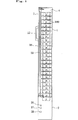
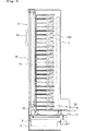
図1−3は、本発明にかかる薬剤払出装置を示す。この薬剤払出装置は、薬剤ケース1と、該薬剤ケース1の下端に一体に設けられた下部ケース2とを有し、下部ケース2には薬剤押出し機構3が収容されている。
FIG. 1-3 shows a medicine dispensing apparatus according to the present invention. This medicine dispensing device has a
薬剤ケース1は、正面、底面、および背面の下部にそれぞれ開口部4,5,6が形成された縦長の矩形の箱からなり、正面の開口部4は扉7によって開閉可能になっている。薬剤ケース1は、本実施形態では、図7に示すブリスターパックからなる複数の薬剤100が上下方向に積載して収容されるようになっている。薬剤ケース1の内部の奥側には、収容される薬剤100のサイズに応じて前後方向に位置調整可能な整列板8が設けられている。同様に、薬剤ケース1の内部の左側には、左右方向に位置調整可能な整列板9(図4(a)参照)が設けられている。
The
扉7は、前記薬剤ケース1の開口部4を開閉するもので、外側に位置する第1扉10と内側に位置する第2扉11とからなっている。第1扉10の外面には取手12が取り付けられている。第1扉10は、左側の上端および下端に形成されたヒンジ凹部13a,13bに、薬剤ケース1の上壁から突出する突出片15に下向きに突設されたヒンジ突部14aと、薬剤ケース1と下部ケース2の間の棚部16に上向きに突設されたヒンジ突部14bとをそれぞれ嵌合することで、薬剤ケース1の開口部4を略90°開閉可能になっている。同様に、第2扉11は、左側の上端および下端に形成されたヒンジ凹部17a,17bに、薬剤ケース1の突出片15に下向きに突設されたヒンジ突部18aと、棚部16に上向きに突設されたヒンジ突部18bとをそれぞれ嵌合することで、薬剤ケース1の開口部4を略90°開閉可能になっている。第2扉11は、本発明の薬剤整列手段を構成している。
The
第2扉11のヒンジ突部18a,18bは、図4に示すように、第1扉10のヒンジ突部13a,13bより斜め後方に配置され、これにより、図4(a)に示すように、扉7を90°開放したときの第1扉10と第2扉11の間隔Aは、図4(c)に示すように、扉7を閉鎖したときの第1扉10と第2扉11の間隔Bより小さくなっている。したがって、間隔Aが狭いので、薬剤ケース1の幅を小さくすることができ、薬剤ケース1を高密度に配置することができる。また、間隔Bが大きいので、薬剤100を薬剤ケース1内のできるだけ後方側に整列させることができ、これに伴って薬剤押出し機構3も後方に配置することができ、下部ケース1の下端から薬剤ケース1の突出量が少なくなり、装置の構造および配置が容易になる。
As shown in FIG. 4, the
第1扉10の上端および下端には内側に向かって突出するカバー板19が設けられ、該カバー板19にはヒンジ凹部13a,13bの近傍から斜めに延びる長孔20が形成されている。一方、第2扉11の上端および下端には、第1扉10のカバー板19に重なるように、突片21が設けられ、該突片21には前記第1扉10のカバー板19の長孔20に係合するピン22が突設されている。ピン22と長孔20は本発明の連動機構を構成している。この連動機構により、図4(a)〜(c)に示すように、第1扉10が開閉すると、ピン22が長孔20を摺動し、第1扉10に連動して第2扉11が開閉するようになっている。
A
第2扉11の下端のヒンジ凹部17bの近傍には、扉7の閉鎖時に、図5に示すように、薬剤ケース1の底の適宜箇所に設けた閉鎖位置検出センサ23に押接する突起24が設けられている。閉鎖位置検出センサ23は、マイクロスイッチからなり、該マイクロスイッチがオンすると、後述する薬剤押出し機構3が通電されて動作可能となる。
In the vicinity of the
前記第1扉10および第2扉11は、ヒンジ凹部13a,13b,17a,17bとヒンジ突部14a,14b,18a,18bが嵌合したまま上下方向に所定範囲内で摺動可能になっている。また第1扉10の下側のカバー板19の下面には、下向きにロック片25が突設されている。このロック片25は、図6に示すように、扉7が90°開放されたときには、棚部16の前縁に係合して扉7を開放状態にロックし、扉7が閉鎖されたときには、棚部16の後縁に係合して扉7を閉鎖状態にロックする本発明のロック機構を構成している。
The
前記下部ケース2の正面には、図1に示すように、欠品表示用発光ランプ26と、エラー表示用発光ランプ27と、エラー解除ボタン28が配設されている。欠品表示用発光ランプ26は、図示しないセンサにより薬剤100の欠品が検出されると点灯するようになっている。エラー表示用発光ランプ27は、欠品状態でない場合に薬剤100の詰まり等によって薬剤100の払出し動作を行っても図示しないセンサにより薬剤100の払出しが検出されないときに点灯するようになっている。エラー解除ボタン28は、薬剤100の詰まりを除去してエラーを解除した後、装置を再起動させるために押すものである。
As shown in FIG. 1, a shortage display light-emitting
下部ケース2内に収容された薬剤押出し機構3は、図2に示すように、前記薬剤ケース1に収容された最下段の薬剤100が載置される2条のレール30と、該レール30の下方にレール30に沿って配置され、モータにより正逆転駆動可能なスクリュねじ31と、該スクリュねじ31に沿って往復移動可能な押出爪32とからなっている。押出爪32は、スクリュねじ31に螺合された基台33に、図2に示すような起立位置と倒伏位置との間でピン34の回りに回動可能に取り付けられ、図示しないばねにより起立位置に向かって付勢されている。
As shown in FIG. 2, the drug push-out
前記薬剤払出装置は、同形状のものが左右に配置されるともに、複数段にわたって配置され、異なる薬剤100を払い出すことができるようになっている。
The medicine dispensing devices having the same shape are arranged on the left and right sides, and are arranged in a plurality of stages so that
次に、前記構成からなる薬剤払出装置の動作について説明する。 Next, the operation of the medicine dispensing device having the above configuration will be described.
まず、薬剤100の払出し動作について説明すると、スクリュねじ31を正転して押出爪32を後方に向かって移動させる。これにより、薬剤ケース1内に積層された複数の薬剤100のうち最下段の薬剤100は、図2中実線で示す始端位置で起立状態にある押出爪32に押圧され、後方に向かってレール30上を移動して押し出され、図示しないトレイに収容された後、所定の径路を経て外部に払い出される。最下段の薬剤100が押し出されると、2段目の薬剤100がレール30上に自重で降下する。続いて、スクリュねじ31を逆転させる。これにより、図中2点鎖線で示す終端位置にある押出爪32´が前方に向かって移動し、薬剤100の後端に当接して倒伏状態となり、薬剤100の下を通って実線で示す始端位置に戻って起立状態となる。以上の動作を繰り返すことで、薬剤100を順次払い出すことができる。
First, the dispensing operation of the
薬剤100が欠品すると、薬剤ケース1の扉7を開放して薬剤ケース1に薬剤100を積み重ねて充填する。扉7の開放は、取手12を持って上方に摺動させ、図5(a)に示すように、ロック片25と棚部16の後端との係合を解除してから行う。第1扉10を開放してゆくと、これに連動して第2扉11が開放される。扉7が90°開放されると、図6(a)に示すように、ロック片25が棚部16から外れて下方に摺動し、棚部16の前端に係合するので、扉7は開放状態にロックされる。
When the
扉7が開放されると、薬剤100を薬剤ケース1に充填する。このとき、薬剤100を順次積載してゆくだけでよく、薬剤100を整列させる必要はない。なお、扉7を開放したとき、図5(a)に示すように、扉7の突起24が閉鎖位置検出センサ23から離脱するので、薬剤押出し機構3への通電が遮断され、駆動が不能とされる。したがって、薬剤100の充填中に薬剤100の払出動作が行われることがなく、安全である。また、前述のように扉7は開放状態にロックされているので、薬剤100の充填中に動くことがなく、充填作業が円滑に行える。
When the
薬剤ケース1内への薬剤100の充填が終了すると、扉7を閉鎖する。扉7の閉鎖は、開放時と同様に、扉7の取手12を持って上方に摺動させ、ロック片25と棚部16の前端との係合を解除してから行う。第1扉10を閉鎖してゆくと、図4(a)から(c)に示すように、これに連動して第2扉11が閉鎖される。そして、扉7が完全に閉鎖されると、図4(c)に示すように、第2扉11の内面が充填した複数の薬剤100の前端を押圧して後端が整列板8に当接することで整列させられる。扉7を押し戻したとき、図6(b)に示すように、ロック片25が棚部16から外れて下方に摺動し、棚部16の後端に係合するので、扉7は閉鎖状態にロックされる。また、扉7を閉鎖したとき、図5(b)に示すように、扉7の突起24が閉鎖位置検出センサ23を押接するので、錠剤押出し機構3の駆動が可能となる。
When filling of the
なお、前記実施形態では第1扉10と第2扉11の連動機構としてピンと長孔とで構成したが、これに限定されるものではなく、ギヤ、プーリ等で構成してもよい。
In the above-described embodiment, the interlocking mechanism of the
また、前記実施形態は、図7に示すブリスターパックを払い出す薬剤払出装置であるが、図8に示すヒート錠剤や、図9に示す箱入りの特殊アンプル等を払い出す薬剤払出装置にも同様の構造で適用可能である。 Moreover, although the said embodiment is a chemical | medical agent dispensing apparatus which dispenses the blister pack shown in FIG. 7, it is the same also to the chemical | medical agent dispensing apparatus which dispenses the heat tablet shown in FIG. 8, the special ampule in a box shown in FIG. Applicable in structure.
Claims (4)
前記薬剤ケースの正面に外側に位置する第1扉と内側に位置する第2扉とで構成される扉を設け、
前記第2扉は、前記扉を閉鎖したときに充填した複数の薬剤の一端を押圧して他端を整列させる薬剤整列手段を構成し、
前記第1扉と第2扉は、それぞれヒンジにより開閉可能に設けるとともに、当該第1扉と第2扉の間隔が閉鎖時よりも開放時のほうが小さくなるようにしたことを特徴とする薬剤払出装置。In a medicine dispensing device that pushes out and horizontally dispenses a plurality of medicines loaded and accommodated in a medicine case in the vertical direction,
Providing a door composed of a first door located outside and a second door located inside on the front of the medicine case;
The second door constitute a drug alignment means for presses align the other end one end of a plurality of drugs filled when closing the door,
The first door and the second door are provided so as to be openable and closable by hinges, respectively, and the medicine dispensing is characterized in that the distance between the first door and the second door is smaller when opened than when closed. apparatus.
Applications Claiming Priority (3)
| Application Number | Priority Date | Filing Date | Title |
|---|---|---|---|
| JP2002305167 | 2002-10-18 | ||
| JP2002305167 | 2002-10-18 | ||
| PCT/JP2003/013119 WO2004035437A1 (en) | 2002-10-18 | 2003-10-14 | Drug dispenser |
Publications (2)
| Publication Number | Publication Date |
|---|---|
| JPWO2004035437A1 JPWO2004035437A1 (en) | 2006-02-09 |
| JP4372012B2 true JP4372012B2 (en) | 2009-11-25 |
Family
ID=32105155
Family Applications (1)
| Application Number | Title | Priority Date | Filing Date |
|---|---|---|---|
| JP2004544943A Expired - Fee Related JP4372012B2 (en) | 2002-10-18 | 2003-10-14 | Drug dispensing device |
Country Status (5)
| Country | Link |
|---|---|
| US (1) | US7311222B2 (en) |
| JP (1) | JP4372012B2 (en) |
| KR (1) | KR101032047B1 (en) |
| TW (1) | TWI300755B (en) |
| WO (1) | WO2004035437A1 (en) |
Families Citing this family (6)
| Publication number | Priority date | Publication date | Assignee | Title |
|---|---|---|---|---|
| US7984824B2 (en) * | 2008-03-18 | 2011-07-26 | Hotel Outsource Management International, Inc. | Sensor assembly |
| US9790017B2 (en) * | 2008-11-21 | 2017-10-17 | Yuyama Mfg. Co., Ltd. | Tablet feeder and pharmacy system |
| EP2455057B1 (en) * | 2009-07-14 | 2017-12-27 | Panasonic Healthcare Holdings Co., Ltd. | Automatic medication dispensing device |
| US20140108027A1 (en) | 2012-10-12 | 2014-04-17 | Mckesson Automation Inc. | Apparatuses, systems, and methods for delivering medications from a central pharmacy to a patient in a healthcare facility |
| US9150119B2 (en) | 2013-03-15 | 2015-10-06 | Aesynt Incorporated | Apparatuses, systems, and methods for anticipating and delivering medications from a central pharmacy to a patient using a track based transport system |
| CN111874359B (en) * | 2020-06-23 | 2022-10-14 | 哈尔滨医大药业股份有限公司 | Quick cartoning device of medicine board and description |
Family Cites Families (14)
| Publication number | Priority date | Publication date | Assignee | Title |
|---|---|---|---|---|
| US1424150A (en) * | 1921-01-05 | 1922-08-01 | Burnham Robert Craig | Vending machine |
| US3367730A (en) * | 1966-07-25 | 1968-02-06 | Vendo Co | Refrigerated dispensing cabinet having outer decorative door and inner locked product access door |
| US3870135A (en) * | 1971-03-17 | 1975-03-11 | Carton Sales Inc | Cigarette carton dispensing system |
| IT1105891B (en) | 1978-04-28 | 1985-11-04 | Martelli Guglielmo | EXHAUST DEVICE FOR SINGLE HIGH SPEED SEPARATION OF TABLETS BLISTER STRIPS TYPE BOXES AND SIMILAR STORABLE PRODUCTS |
| DE3215607A1 (en) * | 1982-04-27 | 1983-10-27 | Paul Hettich & Co, 4983 Kirchlengern | CABINET WITH A DOUBLE DOOR CONSISTING OF AN INTERIOR AND OUTDOOR. |
| JPS59127298A (en) | 1982-11-11 | 1984-07-23 | Fujitsu Ltd | Shift register |
| JPS59127298U (en) * | 1983-02-16 | 1984-08-27 | ホ−ヤ株式会社 | board storage container |
| JPH02130972A (en) | 1988-11-11 | 1990-05-18 | Toshiba Corp | Gas laser tube |
| JPH0732804Y2 (en) * | 1989-04-07 | 1995-07-31 | 富士通株式会社 | Open door stopper and lock mechanism |
| JP2816432B2 (en) * | 1989-07-17 | 1998-10-27 | 東芝メカトロニクス株式会社 | Tablet package inspection device |
| US5143430A (en) * | 1990-09-06 | 1992-09-01 | The Vendo Company | Inner door latch |
| JPH07244328A (en) * | 1994-03-02 | 1995-09-19 | Kyocera Corp | Locking device for back driving af camera |
| JP3808581B2 (en) * | 1997-03-25 | 2006-08-16 | 株式会社湯山製作所 | Injection dispensing device |
| US6578735B1 (en) * | 2000-02-02 | 2003-06-17 | Ewald Mothwurf | Method and an apparatus for promoting a product or brand |
-
2003
- 2003-10-09 TW TW092128137A patent/TWI300755B/en active
- 2003-10-14 US US10/531,450 patent/US7311222B2/en not_active Expired - Fee Related
- 2003-10-14 JP JP2004544943A patent/JP4372012B2/en not_active Expired - Fee Related
- 2003-10-14 WO PCT/JP2003/013119 patent/WO2004035437A1/en active Application Filing
- 2003-10-14 KR KR1020057006298A patent/KR101032047B1/en active IP Right Grant
Also Published As
| Publication number | Publication date |
|---|---|
| JPWO2004035437A1 (en) | 2006-02-09 |
| US20060060596A1 (en) | 2006-03-23 |
| US7311222B2 (en) | 2007-12-25 |
| TW200413220A (en) | 2004-08-01 |
| TWI300755B (en) | 2008-09-11 |
| WO2004035437A1 (en) | 2004-04-29 |
| KR101032047B1 (en) | 2011-05-02 |
| KR20050051694A (en) | 2005-06-01 |
Similar Documents
| Publication | Publication Date | Title |
|---|---|---|
| CA2533265C (en) | Medicine supply apparatus and tablet case | |
| JP4372011B2 (en) | Drug dispensing device | |
| TWI457120B (en) | Cartridge, a medicament dispenser containing the cartridge, and uses of the cartridge and of the medicament dispenser | |
| US9038853B2 (en) | Sanitized vending machine and method | |
| WO2001034090A1 (en) | Solid drug filling device | |
| CN111787900B (en) | Medicine dispensing device | |
| CA2533230C (en) | Medicine supply apparatus | |
| JP4372012B2 (en) | Drug dispensing device | |
| US10414576B2 (en) | Dispensing box for drug-containing ampoule | |
| TWI305631B (en) | Coin deposit apparatus | |
| JP2009022743A (en) | Tablet filler device | |
| JP5357302B2 (en) | Dispensing equipment chemical stock structure | |
| TW201921321A (en) | Dispense device | |
| JP7023846B2 (en) | container | |
| JPH0223401B2 (en) | ||
| JP3465602B2 (en) | Vending machine product delivery device | |
| JP6978281B2 (en) | Book storage device | |
| JP3407188B2 (en) | Vending machine product unloading device | |
| JP3449235B2 (en) | Vending machine product unloading device | |
| CA2811276A1 (en) | Medecine supply apparatus | |
| JP3815309B2 (en) | Vending machine product delivery device | |
| JPS62122903A (en) | Tablet feeder |
Legal Events
| Date | Code | Title | Description |
|---|---|---|---|
| A621 | Written request for application examination |
Free format text: JAPANESE INTERMEDIATE CODE: A621 Effective date: 20060425 |
|
| A131 | Notification of reasons for refusal |
Free format text: JAPANESE INTERMEDIATE CODE: A131 Effective date: 20090324 |
|
| A521 | Written amendment |
Free format text: JAPANESE INTERMEDIATE CODE: A523 Effective date: 20090522 |
|
| TRDD | Decision of grant or rejection written | ||
| A01 | Written decision to grant a patent or to grant a registration (utility model) |
Free format text: JAPANESE INTERMEDIATE CODE: A01 Effective date: 20090804 |
|
| A01 | Written decision to grant a patent or to grant a registration (utility model) |
Free format text: JAPANESE INTERMEDIATE CODE: A01 |
|
| A61 | First payment of annual fees (during grant procedure) |
Free format text: JAPANESE INTERMEDIATE CODE: A61 Effective date: 20090901 |
|
| FPAY | Renewal fee payment (event date is renewal date of database) |
Free format text: PAYMENT UNTIL: 20120911 Year of fee payment: 3 |
|
| R150 | Certificate of patent or registration of utility model |
Free format text: JAPANESE INTERMEDIATE CODE: R150 |
|
| FPAY | Renewal fee payment (event date is renewal date of database) |
Free format text: PAYMENT UNTIL: 20120911 Year of fee payment: 3 |
|
| FPAY | Renewal fee payment (event date is renewal date of database) |
Free format text: PAYMENT UNTIL: 20130911 Year of fee payment: 4 |
|
| R250 | Receipt of annual fees |
Free format text: JAPANESE INTERMEDIATE CODE: R250 |
|
| R250 | Receipt of annual fees |
Free format text: JAPANESE INTERMEDIATE CODE: R250 |
|
| R250 | Receipt of annual fees |
Free format text: JAPANESE INTERMEDIATE CODE: R250 |
|
| R250 | Receipt of annual fees |
Free format text: JAPANESE INTERMEDIATE CODE: R250 |
|
| R250 | Receipt of annual fees |
Free format text: JAPANESE INTERMEDIATE CODE: R250 |
|
| LAPS | Cancellation because of no payment of annual fees |