JP4369552B2 - Mating and fixing type synthetic resin container lid - Google Patents
Mating and fixing type synthetic resin container lid Download PDFInfo
- Publication number
- JP4369552B2 JP4369552B2 JP08981799A JP8981799A JP4369552B2 JP 4369552 B2 JP4369552 B2 JP 4369552B2 JP 08981799 A JP08981799 A JP 08981799A JP 8981799 A JP8981799 A JP 8981799A JP 4369552 B2 JP4369552 B2 JP 4369552B2
- Authority
- JP
- Japan
- Prior art keywords
- container lid
- flap piece
- skirt
- container
- mouth
- Prior art date
- Legal status (The legal status is an assumption and is not a legal conclusion. Google has not performed a legal analysis and makes no representation as to the accuracy of the status listed.)
- Expired - Fee Related
Links
Images


Landscapes
- Closures For Containers (AREA)
Description
【0001】
【発明の属する技術分野】
本発明は、嵌合固定型の合成樹脂製容器蓋に関するものであり、特に牛乳ビンの様に、口部上端に厚肉の周状突部が形成されている容器の蓋として好適に使用し得る嵌合固定型合成樹脂製容器蓋に関する。
【0002】
【従来の技術】
従来、牛乳ビンは、紙製の円板状の蓋をビン口内に嵌め込んで市販されているが、消費者は、この蓋を指で直接ビン口から引き剥がす様にして取り外す場合が多い。従って、この時に、飲み口部であるビン口に指が直接触れてしまい、衛生的でないという問題があった。また、紙製の蓋では、密封性の点でも十分なものであるとはいえない。
【0003】
そこで、最近では、紙製の円板状の蓋に代え、ビン口全体を外側から完全に覆ってしまう様な嵌合固定型の合成樹脂製容器蓋も提案される様になってきた。即ち、この様な合成樹脂製容器蓋は、これを開ける際に、指がビン口に直接接触するのが有効に防止できるので、極めて衛生的であり、また密封性の点でも優れているというものである。
【0004】
この様な嵌合固定型の合成樹脂製容器蓋の代表的なものとして、実公昭47−13109号公報には、瓶口内に密着するように設けた中栓部1と、瓶の外周側面に嵌合するスカート部2とを有し、スカート部2の下端にはつまみ部4が設けられ、且つ、スカート部2の内面下端には、瓶口外周面の凸条と係合する肉厚凸条が設けられている合成樹脂製の簡易瓶蓋が開示されている。
【0005】
【発明が解決しようとする課題】
しかしながら、上記先行技術に開示されている様な構造の簡易瓶蓋には、種々の欠点がある。
即ち、上記先行技術では、スカート部の下端に形成されている肉厚凸条を、瓶口部の外周面に形成された凸条と係合させることにより、瓶蓋を固定している。しかるに、スカート部内面に肉厚の凸条を形成すると、可撓性が失われるため、瓶口からの蓋の取り外し(開封)が著しく困難となってしまう。このため、上記先行技術では、つまみ部の両側にスコアを設け、このスコアを引き裂くことにより、開封を行う構造としている。しかるに、スコアを設ける場合には、その切り込み深さの調整が難しいという問題がある。例えば、スコアの切り込みを深くすると、その引き裂きは容易となるが、反面、瓶蓋に瓶口を打栓により嵌め込む際に、スコア切れ等のトラブルを生じ易くなる。一方、切り込み深さを浅くすると、打栓に際してのスコア切れを防止することはできるが、スコアの引き裂きが困難となってしまう。更に、スコアの引き裂きにより開封を行った場合には、瓶蓋は引き裂かれてしまうため、これを再度、瓶口に装着しての使用ができなくなってしまう。
【0006】
また、スカート部内面に肉厚凸条を設けた瓶蓋は、射出成形等の一体成形により製造されるが、肉厚部分が冷却しにくいため、成型後の金型内での冷却時間が長くなってしまう。さらに、肉厚部は剛性が高く、撓みにくいため、成形後の型抜きに際して、肉厚のアンダーカット部に型が引っ掛かってしまい、成形不良が生じ易くなる。このように、成形サイクルが長くなったり、不良品発生率が高くなったりするなど、生産性の点で問題がある。
【0007】
また、上述した種々の欠点は、この瓶蓋を牛乳ビンに適用する場合には、一層顕著となる。即ち、牛乳ビンの口部外周に設けられている凸条は、全体として曲率半径が極めて大きななだらかな曲面で構成されている。従って、スカート部内面に形成される凸条の肉厚を一層大きくすることが必要となるが、この肉厚が大きくなる程、前述した欠点が顕著なる。
【0008】
従って、本発明の目的は、容器口部にしっかりと固定され且つ十分な開栓性及び密封性を有し、特に牛乳ビンのように、口部外周に曲率半径が大きい厚肉の周状突部が形成されている容器に適用された場合にも、このような特性が保持される嵌合型の合成樹脂製容器蓋を提供することにある。
【0009】
【課題を解決するための手段】
本発明によれば、頂板部と、頂板部の周縁部から垂下したスカート部とから成り、該スカート部内に容器口部が嵌め込まれる嵌合固定型の合成樹脂製容器蓋において、前記スカート部内面の下方部分には、周方向に間隔を置いて複数のフラップ片が間欠的に設けられており、前記フラップ片は、先端部が付け根部より下方に位置する様に成形され、その後、容器蓋を容器口部に嵌合固定する前又は嵌合固定する時、垂直断面で見て、その先端部が付け根部よりも上方に位置する様に付け根部を支点として上向きに反転されたものであり、反転された状態の前記フラップ片の径方向内側に係止用突面を備えており、スカート部内に容器口部が嵌め込まれた状態において、前記フラップ片の係止用突面と反対側に形成されたフラットな面は、スカート部内面に密着し、且つ前記係止用突面は容器口部の外周面に圧接されていることを特徴とする嵌合固定型の合成樹脂製容器蓋が提供される。
【0010】
本発明の合成樹脂製蓋においては、スカート部内面に周方向に間隔を置いて複数のフラップ片を間欠的に設けたことが重要な特徴である。
これらのフラップ片は、容器口部に嵌合固定された状態において、その先端部が付け根部よりも上方に位置するように付け根部を支点として上向きに反転された形状を有しており、その先端部と付け根部下側とに連なる様に形成されている係止用突面を備えている。
即ち、容器蓋が容器口部に嵌合固定されると、これらフラップ片は、容器口部の外周面とスカート部内面との間に挟持され、該フラップ片の先端部と付け根部との間の面はスカート部内面と接触し、且つ前記係止用突面は、容器口部の外周面に圧接される。従って、牛乳ビンの様に、大きな曲率半径を有し、しかも明確な段差部を有していない様な厚肉の周状突部が口部外面に形成されている容器に適用した場合にも、フラップ片の係止用突面と容器口部外周面(厚肉の周状突部の外面)との圧接により、この容器蓋を、容器口部にしっかりと固定することができるのである。
【0011】
また、このようなフラップ片の係止用突面と容器口部外周面とを圧接させた時には、容器口部外周面には、常時、上向きの反力が作用する。この結果、容器口部の上端は、容器蓋の頂板部内面に、常時、押し付けられた状態に保持され、極めて高い密封性が得られるのである。
しかも、上記フラップ片は、付け根部を支点としての上方への反転により形成されているものであることから判る様に、可撓性に富んでいると共に、スカート部内面の全周にわたって形成されているものではなく、周方向に間隔を置いて複数形成されている。この結果、この容器蓋は、容器口部にしっかりと固定されながらも、例えばスカート部外面に形成された開封用タブを持っての引き抜きにより、容易に容器口部から取り除くことができ、開封のために、スコアの引き裂き等を要しない。
また、容器蓋を引き裂くことにより開封を行うものではないことから、本発明の容器蓋は、一度開封した後も、再度容器口部に装着してリシールすることもできる。
さらに、このフラップ片は、下向きの形状で成形されるため、成形後の型抜きも容易に行うことができるし、フラップ片は、従来公知の容器蓋のスカート部内面に設けられている厚肉の突条を、スカート部内面とは切り離した形で形成されるため、成形後の冷却にも時間がかからず、極めて生産性が高い。
【0012】
かかる本発明においては、スカート部内面の中央部分に、下側の内径が大きくなるような段差を周状に形成し、前記フラップ片を、該段差の下方に形成することが好ましい。このような段差を形成しておくと、スカート部内に容器口部が嵌め込まれた状態において、反転しているフラップ片は、段差の下側空間に入り込む。即ち、反転しているフラップ片の係止用突面と、段差よりも上方のスカート部内面とを滑らかに連続させることができる。この結果、この段差のすぐ上のスカート部内面から容器口部外周面を密着させることができ、容器蓋のがたつき等を有効に防止でき、且つ密封性の点でも好適となる。
【0013】
また、本発明において、前記フラップ片の係止用突面とは反対側の面、即ち、先端部と付け根部上側とに連なる面をフラットに形成し、スカート部内に容器口部が嵌め込まれた状態において、このフラットな面がスカート部内面に密着するようにすることが好適である。即ち、係止用突面とスカート部内面とを密着させることにより、反転したフラップ片が不規則に変形することがなく、容器口部の外周面と係止用突面との圧接力は、周方向全体にわたって均一となり、安定して蓋を容器口部に固定することができる。
【0014】
更に、スカート部内面の段差の下側に、各フラップ片に対応して、それぞれ台座を設けることが好ましい。この台座は、下方に向かって径方向内方向側に傾斜しているテーパー面を有するものであり、この台座のテーパー面の下端部分に、フラップ片の付け根部が形成される。このような台座を設けた場合には、フラップ片の反転がスムーズに行われる。しかも、フラップ片の係止用突面の反対側面をフラットな面で形成した場合、このフラットな面全体(付け根部から先端部迄)を、台座のテーパー面に密着させることができ、容器蓋を容器口部に嵌合固定する時のフラップ片の変形等を有効に防止し、且つ係止用突面と容器口部外周面との圧接力を、周方向全体にわたって均一にする上でも好適である。
【0015】
【実施例】
本発明を、添付図面に示す具体例に基づいて詳細に説明する。
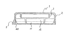
図1は、本発明の合成樹脂製容器蓋の成形直後の形状を示す側断面図であり、
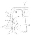
図2は、図1の容器蓋の要部を拡大して示す側断面図であり、
図3は、図1の容器蓋の底面図であり、
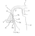
図4は、図1の容器蓋を牛乳ビンのビン口に嵌合固定した状態を示す要部拡大側断面図である。
図5は、本発明の合成樹脂製容器蓋の他の例において、ビン口に装着する直前の状態の要部拡大側面図であり、
図6は、図5の底面図であり、
図7は、図1の容器蓋を、容器口部に嵌合固定した状態を示す要部拡大側断面図である。
【0016】
図1乃至図4に示した本発明の合成樹脂製容器蓋は、特に図1乃至図3に示されている様に、頂板部1、頂板部1の周縁部から垂下したスカート部2とから成り、頂板部1の内面には、スカート部2と間隔を置いてインナーリング4が設けられている。即ち、図4に示されている様に、このスカート部2とインナーリング4との間に牛乳ビンのビン口部50が嵌め込まれて固定される構造となっている。
またスカート部2の外面の下端には、開封用タブ5が設けられており、このタブ5を指で摘んでスカート部2を捲り上げることにより、容器蓋をビン口50から取り除いて開封することができる。
【0017】
図1、図3と共に図2の要部拡大側断面図を参照して、この容器蓋においては、スカート部2の内面の中央部に、周状に段差10が形成されており、この段差10よりも下方のスカート部2の内径が、それよりも上方のスカート部2の内径よりも大きくなっている。
また、段差10の下側には、段差10とは間隔を置いて、フラップ片11が、周方向に間隔をおいて間欠的に複数配置されている。図1、2に示されている様に、これらのフラップ片11は、成形直後においては、下方を指向しており、その先端部11aは、その付け根部11bよりも下方に位置している。従って、この容器蓋は、成形後の型抜きを極めて容易に行い得るようになっている。
即ち、この容器蓋は、成形後にフラップ片11をポンチ等の適宜の型により反転させて上向きの状態に反転させ、しかる後に、図4に示す様に、ビン口部50に嵌合固定される。
【0018】
段差10の下側のスカート部2の内面には、薄肉の台座15が、各フラップ片11に対応して設けられており、フラップ片11の付け根部11bは、台座15の下端に接続されている。
上記の台座15は、段差10のすぐ下側から径内方に傾斜したテーパー面15aを有しており、下方にいくにしたがって、この台座15の厚みは少しずつ厚くなるようになっている。
【0019】
フラップ片11は、特に図2から明らかな様に、その先端部11aと付け根部11bの下側(図中Aで示す)とに連なる係止用突面12を有しており、この係止用突面12と反対側の面13、即ち、先端部11aと付け根部11bの上側(図中Bで示す)とに連なる面13は、フラットな面となっている。
【0020】
即ち、この容器蓋を成形した後に、フラップ片11は先端部11aが上向きとなるように反転され、図4に示す様に容器蓋がビン口部50に固定されると、先端部11aが付け根部11bよりも上方となるように上向きに反転されたフラップ片11は、段差10の下側空間に入り込み、フラップ片11のフラットな面13は、全体にわたって台座15のテーパー面15aと密着し、且つフラップ片11の係止用突面12は、ビン口部50に形成されている厚肉の周状突部51の外面に圧接される。即ち、フラップ片11は、スカート部2の内面とビン口部50の厚肉の周状突部51との間にサンドイッチされた状態となり、これにより、容器蓋はしっかりとビン口部50に固定される。
【0021】
この場合、ビン口部50の厚肉の周状突部51には、フラップ片11の係止用突面12との圧接により、上向きの反力が作用する。従って、ビン口部50の上端は、容器蓋の頂板部1の内面に押し付けられ、この結果、極めて高い密封性が得られる。また、上記のような形状のフラップ片11は、型抜きや成形後の冷却性の問題もないばかりか、それ自体可撓性を有しており、しかも周方向に間隔を置いて間欠的に設けられている。従って、この容器蓋はビン口部50にしっかりと固定されているにもかかわらず、開栓性も良好であり、開封用タブ5を手で持っての引き抜きにより、容易にビン口部50から取り外すことができる。
【0022】
更に上述した容器蓋においては、スカート部2の内面に段差10が設けられていることから、ビン口部50に嵌合固定した状態において、反転したフラップ片11の先端部11aは、段差10の下側空間に入り込み、図4に示されている様に、その係止用突面12と、段差10の上側のスカート部2の内面とは、ほぼ連続的な面を形成する。この結果、段差10の直ぐ上側のスカート部2の内面もビン口部50の厚肉周状突部51の外周面に密着するようになり、更に高い密封性が得られ、しかも容器蓋のがたつき等を生じることもない。
【0023】
また図4において、上記フラップ片11は、係止用突面12とは反対側のフラットな面13が、付け根部11bから全体にわたって台座15のテーパー面15aとぴったりと密着する。このため、反転したフラップ片11が異形変形せず、周方向全体にわたって均一な嵌合力が保持され、安定した密封性が確保される。
【0024】
さらに図2を参照して、本発明のフラップ片11による嵌合力は、係止用突面12の高さhにより容易に調整することができる。即ち、この高さhを大きく設定すれば、嵌合力は高められるが開栓性は低下する。一方、高さhを小さくすると、開栓性は向上するが、嵌合力は低下する。従って、ビン口50に形成されている厚肉の周状突部51の外面形状に合わせて高さhを設定することにより、適度な嵌合力を開栓性とを確保することができる。
【0025】
図3を参照して、本発明において、周方向全体にわたって間欠的に配置されているフラップ片11の数は、各フラップ片11の幅が容易に反転し得る様な大きさである限り特に制限されないが、隣り合うフラップ片11の間隔dが大き過ぎると、嵌合力が局部的に低下してしまい、シール性が損なわれたり、容器蓋がビン口50からすっぽ抜けたりし易くなるから、フラップ片11の係止用突面12の突出量との関係で、この間隔dを適宜の値に選択する。
【0026】
上述した様に、フラップ片11は、容器蓋成形後に、ポンチ等を用いて打栓前に予め反転させておくこともできるが、打栓により、ビン口部50をスカート部2内に嵌め込む時に直接反転させることもできる。一般的には、打栓前にある程度反転させておくことが、打栓操作を容易にするために好適である。
【0027】
また図1、2から理解される様に、成形直後のフラップ片11は、全体的にスカート部2の下端よりも上方に位置している。このため、スカート部2の下方部分がフラップ片11のガイドとなり、成形された容器蓋の支持搬送を容易に行うことができ、また容器蓋搬送時のフラップ片の破損等を有効に防止することができる。更に、スカート部2の下端内面から、フラップ片11の付け根11bにかけて、内径が漸次減少する様に傾斜した面40を形成しておくことが好ましい。これにより、容器蓋をビン口部50に嵌合固定する際に、この傾斜面40がガイドとなり、ビン口部50への容器蓋の嵌合を容易に行うことができる。
【0028】
本発明においては種々の設計変更が可能であり、例えば図1乃至図4の容器蓋では、フラップ片11がかなり幅広に形成されているが、各フラップ片11を小幅のものとして多数形成することもできるし、またフラップ片11の付け根部12を、スカート部2の下端に配置することもできる。このような容器蓋の例を図5の要部側断面図及び図6の底面図に示し、該容器蓋をビン口部50に嵌合固定した状態の要部側断面図を図7に示した。
【0029】
即ち、図5乃至図7で示されている容器蓋は、フラップ片11が小幅のものであり、多数形成されていること、及びフラップ片12の付け根部12がスカート部2の下端に形成されている点を除けば、図1に示されている容器蓋と実質的に同じ構造であり、嵌合力や開封性の点でもほとんど同じ機能を有している。
【0030】
またこの容器蓋は、フラップ片11の付け根11bがスカート部2の内面の下端に形成されていることから、容器蓋成形直後に、このフラップ片11を反転させ、図5に示されている様に、このフラップ片11がスカート部2の下端から外方に突出しないようにしておくことが好ましい。フラップ片11がスカート部2の下端から突出していると、打栓域への容器蓋の支持搬送が行い難くなり、また搬送時にフラップ片の変形や破損を生じ易くなるためである。
ただ付け根部11bをスカート部2の下端に位置せしめた場合には、これをビン口部50に装着した時に、スカート部2の下端とビン口50の外周面との間隔が小さくなるため、この容器蓋の上にシュリンクフィルムなどを被覆し易くなるという利点がある。
【0031】
尚、図1乃至4に示した容器蓋では、特に図4から明らかな通り、フラップ片11の係止用突面12の頂点12aから先端部11a迄の全体にわたって、ビン口部50の厚肉周状突起51の外周面に密着しているが、図5乃至7の容器蓋では、特に図7から明らかな通り、係止用突面12の頂点12aの近傍部分のみが厚肉周状突起51の外周面に密着している。即ち、係止用突面12と厚肉周状突起51の外周面との圧接力が十分に確保されている限り、必ずしも図4の様に、両者が広い面積で密着している必要はない。
【0032】
また、上述した図1乃至図6の例では、スカート部2の内面に段差10を設けた例を示したが、この場合においても、係止用突面12と厚肉周状突起51の外周面との圧接力が十分に確保され、十分な密封性が得られ且つ容器蓋のがたつきが有効に防止される限り、段差10を設けないことも可能である。
更に、前述した本発明の容器蓋は、何れも牛乳ビンに適用されているが、これを他の容器、例えば口部外周に明確な段差部を有するような容器にも、本発明の合成樹脂製容器蓋を適用することができる。
【0033】
上述した合成樹脂製容器蓋は、種々のプラスチックにより形成することができる。具体的には、ポリエチレン、プロピレン−エチレン共重合体、プロピレン−ブテン1共重合体等のオレフィン樹脂;アクリロニトリル−スチレン−ブタジエン(ABS)樹脂;耐衝撃性スチレン樹脂;アクリル樹脂;ナイロン樹脂等、特に好ましくは高密度ポリエチレン、ポリプロピレン等を例示することができ、これらのプラスチックを用いての射出成形、圧縮成形等により、成形することができる。
【0034】
【発明の効果】
本発明によれば、スカート部の内面に、反転により上方を指向している複数のフラップ片を周方向に間隔を置いて設け、各フラップ片の係止用突面を容器口部の外周面と密着させて嵌合固定させることにより、牛乳ビンのように、口部外周に曲率半径が大きく、明確な段差を有していないような厚肉の周状突部が形成されている容器に適用された場合にも、しっかりと固定され且つ十分な開栓性を確保することが可能となった。
特に、この容器蓋は、開栓の為にスコアの引き裂きを行う必要もなく、また型抜き性や成形終了後の冷却性も良好であり、生産性の点でも優れている。
【図面の簡単な説明】
【図1】本発明の合成樹脂製容器蓋の成形直後の形状を示す側断面図。
【図2】図1の容器蓋の要部を拡大して示す側断面図。
【図3】図1の容器蓋の底面図。
【図4】図1の容器蓋を牛乳ビンのビン口に嵌合固定した状態を示す要部拡大側断面図。
【図5】本発明の合成樹脂製容器蓋の他の例において、ビン口に装着する直前の状態の要部拡大側面図。
【図6】図5の容器蓋の底面図。
【図7】図5の容器蓋を、牛乳ビンのビン口に嵌合固定した状態を示す要部拡大側断面図。
【符号の説明】
1: 頂板部
2:スカート部
3:インナーリング
5:開封用タブ
10:段差
11:フラップ片
11a:フラップ片先端部
11b:フラップ片付け根部
12:フラップ片の係止用突面
13:フラップ片の係止用突面とは反対側のフラットな面
15:台座
15a:台座のテーパー面
50:ビン口部
51:厚肉の周状突部[0001]
BACKGROUND OF THE INVENTION
TECHNICAL FIELD The present invention relates to a fitting-fixed type synthetic resin container lid, and particularly suitable for use as a lid of a container having a thick circumferential protrusion formed at the upper end of a mouth, such as a milk bottle. The present invention relates to a fitting and fixing type synthetic resin container lid to be obtained.
[0002]
[Prior art]
Conventionally, milk bottles are commercially available with a paper disk-like lid fitted into the bottle mouth, but consumers often remove the lid by peeling it directly from the bottle mouth with their fingers. Therefore, at this time, there is a problem that the finger directly touches the bottle mouth which is the drinking mouth portion, which is not hygienic. Further, a paper lid is not sufficient in terms of sealing performance.
[0003]
Therefore, recently, instead of a paper disk-shaped lid, a fitting and fixing type synthetic resin container lid that completely covers the entire bottle mouth from the outside has been proposed. That is, such a synthetic resin container lid is very hygienic and excellent in terms of sealing because it can effectively prevent fingers from coming into direct contact with the bottle mouth when opening the container lid. Is.
[0004]
As a typical example of such a fitting and fixing type synthetic resin container lid, Japanese Utility Model Publication No. 47-13109 discloses an
[0005]
[Problems to be solved by the invention]
However, the simple bottle lid having the structure as disclosed in the above prior art has various drawbacks.
That is, in the above prior art, the bottle lid is fixed by engaging the thick ridge formed on the lower end of the skirt portion with the ridge formed on the outer peripheral surface of the bottle mouth portion. However, when a thick ridge is formed on the inner surface of the skirt portion, flexibility is lost, so that removal (opening) of the lid from the bottle mouth becomes extremely difficult. For this reason, in the above prior art, a score is provided on both sides of the knob portion, and the score is opened to tear the score. However, when a score is provided, there is a problem that it is difficult to adjust the depth of cut. For example, if the score cut is deepened, the tearing is facilitated, but on the other hand, when the bottle mouth is fitted into the bottle lid with a stopper, troubles such as score breakage are likely to occur. On the other hand, when the cutting depth is shallow, it is possible to prevent score breakage at the time of plugging, but it becomes difficult to tear the score. Further, when opening is performed by tearing the score, the bottle lid is torn, so that it cannot be used again by attaching it to the bottle mouth.
[0006]
In addition, bottle caps with thick ridges on the inner surface of the skirt are manufactured by integral molding such as injection molding. However, because the thick part is difficult to cool, the cooling time in the mold after molding is long. turn into. Furthermore, since the thick portion has high rigidity and is difficult to bend, the die is caught by the thick undercut portion when the die is removed after molding, and molding defects are likely to occur. Thus, there is a problem in terms of productivity, such as a longer molding cycle and a higher incidence of defective products.
[0007]
In addition, the various drawbacks described above become more prominent when this bottle lid is applied to a milk bottle. In other words, the ridge provided on the outer periphery of the mouth of the milk bottle is composed of a gentle curved surface having a very large curvature radius as a whole. Therefore, it is necessary to further increase the thickness of the ridges formed on the inner surface of the skirt portion. However, as the thickness increases, the above-described drawback becomes more significant.
[0008]
Accordingly, an object of the present invention is to provide a thick circumferential protrusion with a large curvature radius on the outer periphery of the mouth, such as a milk bottle, which is firmly fixed to the container mouth and has sufficient opening and sealing properties. An object of the present invention is to provide a fitting type synthetic resin container lid that retains such characteristics even when applied to a container in which a portion is formed.
[0009]
[Means for Solving the Problems]
According to the present invention, in the fitting and fixing type synthetic resin container lid that includes a top plate portion and a skirt portion that hangs down from the peripheral portion of the top plate portion, and a container mouth portion is fitted into the skirt portion, the inner surface of the skirt portion A plurality of flap pieces are provided intermittently at intervals in the circumferential direction at the lower portion of the container, and the flap pieces are formed such that the tip portion is positioned below the base portion, and then the container lid Before or when fitted and fixed to the container mouth, when viewed from a vertical cross-section, it is inverted upward with the base as a fulcrum so that its tip is located above the base The flap piece is provided with a locking projection surface on the radially inner side of the flap piece in an inverted state, and on the side opposite to the locking projection surface of the flap piece in a state where the container mouth portion is fitted in the skirt portion. the formed flat surfaces, ska In close contact with the isolation portion inner surface, and the locking protruding surface is fitted and fixed type plastic container closure of which is characterized by being pressed against the outer peripheral surface of the container mouth portion is provided.
[0010]
In the synthetic resin lid of the present invention, it is an important feature that a plurality of flap pieces are intermittently provided on the inner surface of the skirt portion at intervals in the circumferential direction.
These flap pieces have a shape that is inverted upward with the base portion as a fulcrum so that the tip portion is located above the base portion in a state of being fitted and fixed to the container mouth portion, A locking protrusion is formed so as to be continuous with the tip and the bottom of the base.
That is, when the container lid is fitted and fixed to the container mouth portion, these flap pieces are sandwiched between the outer peripheral surface of the container mouth portion and the inner surface of the skirt portion, and between the front end portion and the base portion of the flap piece. This surface is in contact with the inner surface of the skirt portion, and the locking projection surface is in pressure contact with the outer peripheral surface of the container mouth portion. Therefore, even when applied to a container having a large radius of curvature, such as a milk bottle, and a thick circumferential protrusion that does not have a clear stepped portion formed on the outer surface of the mouth. The container lid can be firmly fixed to the container mouth by pressure contact between the locking protrusion of the flap piece and the outer peripheral surface of the container mouth (the outer surface of the thick circumferential protrusion).
[0011]
Further, when such a locking projection surface of the flap piece is brought into pressure contact with the outer peripheral surface of the container mouth, an upward reaction force is always applied to the outer peripheral surface of the container mouth. As a result, the upper end of the container mouth portion is always kept pressed against the inner surface of the top plate portion of the container lid, and extremely high sealing performance is obtained.
Moreover, as can be seen from the fact that the flap piece is formed by reversing upward with the base portion as a fulcrum, the flap piece is rich in flexibility and formed over the entire inner circumference of the skirt portion. It is not what is formed, but a plurality are formed at intervals in the circumferential direction. As a result, the container lid can be easily removed from the container mouth by pulling it with a tab for opening formed on the outer surface of the skirt, for example, while being firmly fixed to the container mouth. Therefore, it is not necessary to tear the score.
Further, since the container lid is not opened by tearing the container lid, the container lid of the present invention can be re-sealed by being attached to the container mouth portion again after being opened once.
Further, since this flap piece is molded in a downward shape, it can be easily punched after molding, and the flap piece is a thick wall provided on the inner surface of the skirt portion of a conventionally known container lid. Is formed in a shape separated from the inner surface of the skirt portion, so cooling after molding does not take time, and productivity is extremely high.
[0012]
In the present invention, it is preferable that a step having a large lower inner diameter is formed in a central portion of the inner surface of the skirt portion, and the flap piece is formed below the step. If such a level | step difference is formed, in the state by which the container opening part was engage | inserted in the skirt part, the flap piece inversion will enter into the lower space of a level | step difference. That is, it is possible to smoothly continue the locking projection surface of the inverted flap piece and the inner surface of the skirt portion above the step. As a result, the outer peripheral surface of the container mouth can be brought into close contact with the inner surface of the skirt portion immediately above the step, which can effectively prevent rattling of the container lid and the like, and is also preferable in terms of sealing performance.
[0013]
Further, in the present invention, the surface on the side opposite to the locking projection surface of the flap piece, that is, the surface continuous to the tip portion and the upper base portion is formed flat, and the container mouth portion is fitted in the skirt portion. In the state, it is preferable that the flat surface is in close contact with the inner surface of the skirt portion. That is, by bringing the locking projection surface and the inner surface of the skirt portion into close contact with each other, the inverted flap piece is not irregularly deformed, and the pressure contact force between the outer peripheral surface of the container mouth portion and the locking projection surface is: It becomes uniform over the entire circumferential direction, and the lid can be stably fixed to the container mouth.
[0014]
Furthermore, it is preferable to provide a pedestal corresponding to each flap piece below the step on the inner surface of the skirt portion. This pedestal has a tapered surface that is inclined radially inward toward the lower side, and a base portion of the flap piece is formed at the lower end portion of the tapered surface of the pedestal. When such a pedestal is provided, the flap pieces are smoothly reversed. In addition, when the opposite side surface of the flap protrusion is formed as a flat surface, the entire flat surface (from the base to the tip) can be brought into close contact with the taper surface of the pedestal. It is also suitable for effectively preventing deformation of the flap piece when fitting and fixing the container to the container mouth and making the pressure contact force between the locking projection surface and the outer periphery of the container mouth uniform over the entire circumferential direction. It is.
[0015]
【Example】
The present invention will be described in detail based on specific examples shown in the accompanying drawings.
FIG. 1 is a side sectional view showing a shape immediately after molding of a synthetic resin container lid of the present invention,
FIG. 2 is an enlarged side sectional view showing a main part of the container lid of FIG.
FIG. 3 is a bottom view of the container lid of FIG.
FIG. 4 is an enlarged cross-sectional side view of a main part showing a state where the container lid of FIG. 1 is fitted and fixed to the bottle mouth of the milk bottle.
FIG. 5 is an enlarged side view of a main part in a state immediately before being attached to a bottle mouth in another example of the synthetic resin container lid of the present invention,
FIG. 6 is a bottom view of FIG.
FIG. 7 is an enlarged cross-sectional side view of a main part showing a state in which the container lid of FIG. 1 is fitted and fixed to the container mouth.
[0016]
The synthetic resin container lid of the present invention shown in FIGS. 1 to 4 includes a
Further, an
[0017]
Referring to FIGS. 1 and 3 together with the enlarged side sectional view of the main part of FIG. 2, in this container lid, a
In addition, a plurality of flap pieces 11 are intermittently disposed below the
In other words, the container lid is inverted after being molded by flipping the flap piece 11 with an appropriate mold such as a punch so as to be turned upward, and then fitted and fixed to the
[0018]
A
The
[0019]
As is clear from FIG. 2 in particular, the flap piece 11 has a locking
[0020]
That is, after molding the container lid, the flap piece 11 is inverted so that the tip end portion 11a faces upward, and when the container lid is fixed to the
[0021]
In this case, an upward reaction force acts on the thick
[0022]
Further, in the container lid described above, since the
[0023]
In FIG. 4, the flap piece 11 has a
[0024]
Further, referring to FIG. 2, the fitting force by the flap piece 11 of the present invention can be easily adjusted by the height h of the locking
[0025]
Referring to FIG. 3, in the present invention, the number of flap pieces 11 that are intermittently arranged over the entire circumferential direction is particularly limited as long as the width of each flap piece 11 can be easily reversed. However, if the distance d between the adjacent flap pieces 11 is too large, the fitting force is locally reduced, the sealing performance is impaired, and the container lid is easily removed from the
[0026]
As described above, the flap piece 11 can be inverted in advance by using a punch or the like after the container lid is formed, and before the stopper is plugged, but the
[0027]
As understood from FIGS. 1 and 2, the flap piece 11 immediately after molding is located above the lower end of the
[0028]
In the present invention, various design changes can be made. For example, in the container lid of FIGS. 1 to 4, the flap pieces 11 are formed so as to be quite wide. Alternatively, the
[0029]
That is, in the container lid shown in FIGS. 5 to 7, the flap piece 11 has a small width and is formed in a large number, and the
[0030]
In addition, since the base 11b of the flap piece 11 is formed at the lower end of the inner surface of the
However, when the base portion 11b is positioned at the lower end of the
[0031]
In addition, in the container lid shown in FIGS. 1 to 4, as is apparent from FIG. 4 in particular, the thick wall of the
[0032]
Further, in the examples of FIGS. 1 to 6 described above, the example in which the
Furthermore, the container lid of the present invention described above is applied to milk bottles. However, the synthetic resin of the present invention can be applied to other containers such as a container having a clear stepped portion on the outer periphery of the mouth. A container lid can be applied.
[0033]
The above-described synthetic resin container lid can be formed of various plastics. Specifically, olefin resins such as polyethylene, propylene-ethylene copolymer, propylene-
[0034]
【The invention's effect】
According to the present invention, on the inner surface of the skirt portion, a plurality of flap pieces directed upward by reversal are provided at intervals in the circumferential direction, and the locking protruding surfaces of the flap pieces are provided on the outer peripheral surface of the container mouth portion. In a container in which a thick peripheral protrusion is formed on the outer periphery of the mouth, such that it has a large radius of curvature and does not have a clear step, like a milk bottle. Even when it is applied, it can be firmly fixed and sufficient openability can be secured.
In particular, this container lid does not require tearing of the score for opening, and also has good die-cutting properties and cooling properties after completion of molding, and is excellent in productivity.
[Brief description of the drawings]
FIG. 1 is a side sectional view showing a shape immediately after molding of a synthetic resin container lid of the present invention.
2 is an enlarged side cross-sectional view showing a main part of the container lid of FIG. 1. FIG.
3 is a bottom view of the container lid of FIG. 1. FIG.
4 is an enlarged side cross-sectional view of a main part showing a state in which the container lid of FIG. 1 is fitted and fixed to a bottle mouth of a milk bottle.
FIG. 5 is an enlarged side view of a main part in a state immediately before being attached to a bottle opening in another example of the synthetic resin container lid of the present invention.
6 is a bottom view of the container lid of FIG. 5. FIG.
7 is an enlarged side cross-sectional view of a main part showing a state in which the container lid of FIG. 5 is fitted and fixed to a bottle mouth of a milk bottle.
[Explanation of symbols]
1: Top plate part 2: Skirt part 3: Inner ring 5: Opening tab 10: Step 11: Flap piece 11a: Flap piece tip part 11b: Flap piece base part 12: Flap piece locking projection 13: Flap piece
Claims (3)
前記スカート部内面の下方部分には、周方向に間隔を置いて複数のフラップ片が間欠的に設けられており、
前記フラップ片は、先端部が付け根部より下方に位置する様に成形され、その後、容器蓋を容器口部に嵌合固定する前又は嵌合固定する時、垂直断面で見て、その先端部が付け根部よりも上方に位置する様に付け根部を支点として上向きに反転されたものであり、反転された状態の前記フラップ片の径方向内側に係止用突面を備えており、
スカート部内に容器口部が嵌め込まれた状態において、前記フラップ片の係止用突面と反対側に形成されたフラットな面は、スカート部内面に密着し、且つ前記係止用突面は容器口部の外周面に圧接されていることを特徴とする嵌合固定型の合成樹脂製容器蓋。In a fitting and fixing type synthetic resin container lid comprising a top plate part and a skirt part hanging from the peripheral part of the top plate part, and a container mouth part is fitted in the skirt part,
In the lower part of the inner surface of the skirt part, a plurality of flap pieces are intermittently provided at intervals in the circumferential direction,
The flap piece is shaped such that the tip is positioned below the base, and then the tip of the flap is viewed in a vertical cross section before or after fitting the container lid to the container mouth. Is flipped upward with the root as a fulcrum so that it is located above the root, and includes a locking protrusion on the radially inner side of the flap piece in the inverted state ,
In a state where the container mouth portion is fitted in the skirt portion, the flat surface formed on the side opposite to the locking protrusion surface of the flap piece is in close contact with the inner surface of the skirt portion, and the locking protrusion surface is the container. A fitting and fixing type synthetic resin container lid characterized by being in pressure contact with the outer peripheral surface of the mouth.
Priority Applications (1)
| Application Number | Priority Date | Filing Date | Title |
|---|---|---|---|
| JP08981799A JP4369552B2 (en) | 1999-03-30 | 1999-03-30 | Mating and fixing type synthetic resin container lid |
Applications Claiming Priority (1)
| Application Number | Priority Date | Filing Date | Title |
|---|---|---|---|
| JP08981799A JP4369552B2 (en) | 1999-03-30 | 1999-03-30 | Mating and fixing type synthetic resin container lid |
Publications (2)
| Publication Number | Publication Date |
|---|---|
| JP2000281105A JP2000281105A (en) | 2000-10-10 |
| JP4369552B2 true JP4369552B2 (en) | 2009-11-25 |
Family
ID=13981309
Family Applications (1)
| Application Number | Title | Priority Date | Filing Date |
|---|---|---|---|
| JP08981799A Expired - Fee Related JP4369552B2 (en) | 1999-03-30 | 1999-03-30 | Mating and fixing type synthetic resin container lid |
Country Status (1)
| Country | Link |
|---|---|
| JP (1) | JP4369552B2 (en) |
-
1999
- 1999-03-30 JP JP08981799A patent/JP4369552B2/en not_active Expired - Fee Related
Also Published As
| Publication number | Publication date |
|---|---|
| JP2000281105A (en) | 2000-10-10 |
Similar Documents
| Publication | Publication Date | Title |
|---|---|---|
| US6959829B2 (en) | Self-adjusting re-sealable spring center seal closure | |
| US6460712B2 (en) | One-piece tamper-evident closure system with a resealable, hinged lid | |
| US6948633B2 (en) | Cup lid having combined straw slot depression and tear back lid retainer | |
| US5806710A (en) | Container and closure lid | |
| US5947323A (en) | Cup lid having combined straw slot depression and tear back lid retainer | |
| JP3990807B2 (en) | Plastic cap | |
| EP0324010A1 (en) | Tear open lid | |
| JPS61273354A (en) | container sealed cap | |
| US4200196A (en) | Bottle top closure | |
| JP3603935B2 (en) | Hinge cap with good separation and disposal | |
| JP5389550B2 (en) | Easy-to-open cap | |
| JP4369552B2 (en) | Mating and fixing type synthetic resin container lid | |
| JP4616505B2 (en) | Hinge cap | |
| US5647494A (en) | Tear-off closure for bottle-shaped containers | |
| JP4778222B2 (en) | How to use the cap of the container, the cap of the container, and the inner packing used for these | |
| JP2000255610A (en) | Cap having pull ring | |
| JP4458458B2 (en) | Can container with overcap | |
| JP4349668B2 (en) | Hinge cap with excellent separation and disposal | |
| JP4205801B2 (en) | Plastic container lid | |
| JP4369549B2 (en) | Resin cap | |
| JP4416199B2 (en) | Resin cap | |
| JP4350440B2 (en) | Cap and combination of cap and container | |
| JP4195248B2 (en) | Plastic cap | |
| JPH08119265A (en) | Unsealing device of resealable container | |
| JP2004331190A (en) | Container lid having inner pressure releasing characteristic |
Legal Events
| Date | Code | Title | Description |
|---|---|---|---|
| A621 | Written request for application examination |
Free format text: JAPANESE INTERMEDIATE CODE: A621 Effective date: 20060228 |
|
| A977 | Report on retrieval |
Free format text: JAPANESE INTERMEDIATE CODE: A971007 Effective date: 20081222 |
|
| A131 | Notification of reasons for refusal |
Free format text: JAPANESE INTERMEDIATE CODE: A131 Effective date: 20090113 |
|
| A521 | Written amendment |
Free format text: JAPANESE INTERMEDIATE CODE: A523 Effective date: 20090311 |
|
| TRDD | Decision of grant or rejection written | ||
| A01 | Written decision to grant a patent or to grant a registration (utility model) |
Free format text: JAPANESE INTERMEDIATE CODE: A01 Effective date: 20090818 |
|
| A01 | Written decision to grant a patent or to grant a registration (utility model) |
Free format text: JAPANESE INTERMEDIATE CODE: A01 |
|
| A61 | First payment of annual fees (during grant procedure) |
Free format text: JAPANESE INTERMEDIATE CODE: A61 Effective date: 20090828 |
|
| R150 | Certificate of patent or registration of utility model |
Free format text: JAPANESE INTERMEDIATE CODE: R150 |
|
| FPAY | Renewal fee payment (event date is renewal date of database) |
Free format text: PAYMENT UNTIL: 20120904 Year of fee payment: 3 |
|
| FPAY | Renewal fee payment (event date is renewal date of database) |
Free format text: PAYMENT UNTIL: 20120904 Year of fee payment: 3 |
|
| FPAY | Renewal fee payment (event date is renewal date of database) |
Free format text: PAYMENT UNTIL: 20130904 Year of fee payment: 4 |
|
| LAPS | Cancellation because of no payment of annual fees |