JP4366552B2 - Caster brake pedal - Google Patents
Caster brake pedal Download PDFInfo
- Publication number
- JP4366552B2 JP4366552B2 JP2000184910A JP2000184910A JP4366552B2 JP 4366552 B2 JP4366552 B2 JP 4366552B2 JP 2000184910 A JP2000184910 A JP 2000184910A JP 2000184910 A JP2000184910 A JP 2000184910A JP 4366552 B2 JP4366552 B2 JP 4366552B2
- Authority
- JP
- Japan
- Prior art keywords
- brake
- brake pedal
- hole
- sliding
- wheel
- Prior art date
- Legal status (The legal status is an assumption and is not a legal conclusion. Google has not performed a legal analysis and makes no representation as to the accuracy of the status listed.)
- Expired - Lifetime
Links
- 239000002184 metal Substances 0.000 claims description 19
- 230000003014 reinforcing effect Effects 0.000 claims description 16
- 238000005452 bending Methods 0.000 claims description 11
- 229920003002 synthetic resin Polymers 0.000 description 2
- 239000000057 synthetic resin Substances 0.000 description 2
- 230000000694 effects Effects 0.000 description 1
- 230000000149 penetrating effect Effects 0.000 description 1
- 230000002787 reinforcement Effects 0.000 description 1
- 230000003068 static effect Effects 0.000 description 1
Images
Landscapes
- Braking Arrangements (AREA)
Description
【0001】
【発明の属する技術分野】
この発明は、搬送用機器類、買い物用カート、その他の運搬車などに使用されるキャスターのブレーキペダルに関するものである。
【0002】
【従来の技術】
従来、搬送用機器類、買い物用カート、その他の運搬車などに使用されるキャスターは、例えば図7〜9に示したように、把持体1と、車輪2と、ブレーキシュー3と、ブレーキペダル4とからなる。
【0003】
把持体1は、金属板を曲げ加工してなるものとしており、取付座5の下方に取り付けられ、両側下部に通孔6を設け、片側に案内孔7を設けたものとしている。
【0004】
車輪2は、合成樹脂成形体からなるものとしおり、中心部に貫通孔(図示せず)を設けたものとしている。
【0005】
ブレーキシュー3は、金属板を曲げ加工してなるものとしており、ブレーキライニング8、案内突起9、上部摺動体10、下部摺動体11および縦長孔12を設けたものとしている。
【0006】
ブレーキペダル4は、金属板を曲げ加工してなるものとしており、略直線形に作成され、両端に操作部13a、13b、中央部に通孔14および略中央上部と略中央下部にそれぞれ摺動辺15a、15bを設けたものとしている。なお、前記操作部13a、13bは、金属板の両端を外側水平方向に折り曲げてなるものとしている。
【0007】
そして、前記ブレーキシュー3のブレーキライニング8が車輪2の上方に配され、把持体1の案内孔7にブレーキシュー3の案内突起9が嵌まり込むようにして、このブレーキシュー3を把持体1に接触させ、把持体1の両側下部の通孔6、車輪2の貫通孔、ブレーキシュー3の縦長孔12およびブレーキペダル4の通孔14に車軸17を貫通させて車輪2を回転自在に取り付け、ブレーキペダル4の摺動辺15a、15bをブレーキシュー3の上部摺動体10、下部摺動体11が摺動するようにしている。
【0008】
【発明が解決しようとする課題】
ところで、上記従来のブレーキ機構におけるブレーキペダル4の操作部13a、操作部13bは、足で踏み付けることにより操作するので、つい力が入ってしまうことがあったり、ブレーキペダル4の摺動辺15a、15bとブレーキシュー3の上部摺動体10、下部摺動体11の間には大きな静摩擦力が働いているので、操作時には意識的に強い力で前記操作部13a、操作部13bを踏み付けることがある。
【0009】
しかしながら、前記ブレーキペダル4の摺動辺15a、15bは金属板そのままの上端辺および下端辺としており、しかも摺動辺15a、15bの間には通孔14を設けているので、ブレーキペダル4の中央部付近が特に強度性に乏しいものとなり、強い力が働くとこの部分から曲がったり、破断してしまったりしてブレーキペダルとして使用できなくなるという課題を有していた。
【0010】
なお、前記ブレーキペダル4を作製する金属板を分厚いものにすれば、前記ブレーキペダル4の中央部付近の強度性を上昇させることはできるが、重量が増加してしまい、根本的な解決策には至らないという課題を有することはいうまでもない。
【0011】
そこで、この発明は、上記従来の課題を解決するものであり、重量を増加させることなく、ブレーキペダルを補強することにより、このブレーキペダルに強い力が働いても曲がったり、破断してしまうことのないキャスターのブレーキペダルを提供することを目的としてなされたものである。
【0012】
【課題を解決するための手段】
そのため、この発明のキャスターのブレーキペダルは、ブレーキペダル4の一端の操作部13aを足で踏み付け、ブレーキペダル4を揺動させることにより、ブレーキペダル4の摺動辺15a、15bをそれぞれブレーキシュー3の上部摺動体10および下部摺動体11が摺動し、ブレーキシュー3が全体的に下げられ、ブレーキシュー3のブレーキライニング8が車輪2に接触しロック状態となり、ブレーキペダル4の他端の操作部13bを足で踏み付け、ブレーキペダル4を揺動させ、元の状態に戻すことにより解除状態となるキャスターにおいて、前記ブレーキペダル4の操作部13a、13bを金属板の両端を外側水平方向に折り曲げてなるものとすると共に、これら操作部13a、13bの間に金属板を外側水平方向に折り曲げてなる補強部16を連設し、さらに前記補強部16から距離をおいてこの補強部16に沿って形成した切り込みSから下方部分を内側に向けて打ち出し、この打ち出した部分の上端辺を前記摺動辺15aとし、下端辺を前記摺動辺15bとしている。
【0013】
さらに、この発明のキャスターのブレーキペダルは、取付座5の下方に取り付けられ、両側下部に通孔6を設け、片側に案内孔7を設けた把持体1と、中心部に貫通孔を設けた車輪2と、ブレーキライニング8、案内突起9、上部摺動体10、下部摺動体11および縦長孔12を設けたブレーキシュー3と、両端に操作部13a、13b、中央部に通孔14および略中央上部と略中央下部にそれぞれ摺動辺15a、15bを設けたブレーキペダル4とからなり、前記ブレーキシュー3のブレーキライニング8が車輪2の上方に配され、把持体1の案内孔7にブレーキシュー3の案内突起9が嵌まり込むようにして、このブレーキシュー3を把持体1に接触させ、把持体1の両側下部の通孔6、車輪2の貫通孔、ブレーキシュー3の縦長孔12およびブレーキペダル4の通孔14に車軸17を貫通させて車輪2を回転自在に取り付け、ブレーキペダル4の摺動辺15a、15bをブレーキシュー3の上部摺動体10、下部摺動体11が摺動するようにしたキャスターにおいて、前記ブレーキペダル4の操作部13a、13bを金属板の両端を外側水平方向に折り曲げてなるものとすると共に、これら操作部13a、13bの間に金属板を外側水平方向に折り曲げてなる補強部16を連設し、さらに前記補強部16から距離をおいてこの補強部16に沿って形成した切り込みSから下方部分を内側に向けて打ち出し、この打ち出した部分の上端辺を前記摺動辺15aとし、下端辺を前記摺動辺15bとしてもよい。
【0014】
【発明の実施の形態】
以下、この発明のキャスターのブレーキペダルの実施の形態を、図面に基づいて詳細に説明する。
【0015】
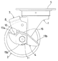
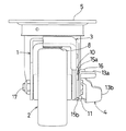
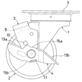
図は、この発明のブレーキペダルを用いたキャスターを示しており、把持体1と、車輪2と、ブレーキシュー3と、ブレーキペダル4とからなる。
【0016】
把持体1は、金属板を曲げ加工してなるものとしており、取付座5の下方に取り付けられ、両側下部に通孔6を設け、片側に案内孔7を設けたものとしている。
【0017】
車輪2は、合成樹脂成形体からなるものとしおり、中心部に貫通孔(図示せず)を設けたものとしている。
【0018】
ブレーキシュー3は、金属板を曲げ加工してなるものとしており、ブレーキライニング8、案内突起9、上部摺動体10、下部摺動体11および縦長孔12を設けたものとしている。
【0019】
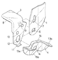
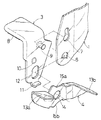
ブレーキペダル4は、金属板を曲げ加工してなるものとしており、略直線形に作成され、両端に操作部13a、13b、中央部に通孔14および略中央上部と略中央下部にそれぞれ摺動辺15a、15bを設けたものとしている。すなわち、前記操作部13a、13bは、金属板の両端を外側水平方向に折り曲げてなるものとしている。そして、これら操作部13a、13bの間には、金属板を外側水平方向に折り曲げてなる補強部16を連設したものとしている。さらに、前記補強部16から少し距離をおいてこの補強部16に沿って形成した切り込みSから下方部分を内側に向けて打ち出し、この打ち出した部分の上端辺を前記摺動辺15aとし、下端辺を前記摺動辺15bとしている。
【0020】
そして、この発明のブレーキペダルを用いたキャスターは、前記ブレーキシュー3のブレーキライニング8が車輪2の上方に配され、把持体1の案内孔7にブレーキシュー3の案内突起9が嵌まり込むようにして、このブレーキシュー3を把持体1に接触させ、把持体1の両側下部の通孔6、車輪2の貫通孔8、ブレーキシュー3の縦長孔12およびブレーキペダル4の通孔14に車軸17を貫通させて車輪2を回転自在に取り付け、ブレーキペダル4の摺動辺15a、15bをブレーキシュー3の上部摺動体10、下部摺動体11が摺動するようにしている。
【0021】
このように構成されたこの発明のブレーキペダルを用いたキャスターは、以下に述べるように作動するようにしている。
【0022】
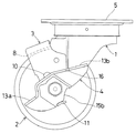
先ず、図1、2に示した状態では、ブレーキシュー3のブレーキライニング8が車輪2から離れ、解除状態にある。そこで、この解除状態から、ブレーキペダル4の一端の操作部13aを足で踏み付けることにより、図6に示した状態にまでブレーキペダル4を揺動させる。
【0023】
すなわち、前記揺動によりブレーキペダル4の摺動辺15a、15bをそれぞれブレーキシュー3の上部摺動体10および下部摺動体11が摺動することにより、ブレーキシュー3が全体的に下げられる。そして、ブレーキシュー3のブレーキライニング8が車輪2に接触するので、キャスターはロック状態となる。
【0024】
次に、この図6のロック状態から前記解除状態にするには、ブレーキペダル4の他端の操作部13bを足で踏み付けることにより、図1、2に示した状態にまで、ブレーキペダル4を揺動させ元の状態に戻せばよい。
【0025】
【発明の効果】
この発明のキャスターのブレーキペダルは、以上に述べたように構成されているので、重量を増加させることなく、ブレーキペダルを補強することができ、このブレーキペダルに強い力が働いても曲がったり、破断してしまうことのないものとなった。
【図面の簡単な説明】
【図1】この発明のブレーキペダルを用いたキャスターの側面図である。
【図2】この発明のブレーキペダルを用いたキャスターの正面図である。
【図3】この発明のブレーキペダルを用いたキャスターの要部分解斜視図である。
【図4】この発明のブレーキペダルの下方向から見た斜視図である。
【図5】この発明のブレーキペダルの平面図である。
【図6】この発明のブレーキペダルの作動状態を示す説明図である。
【図7】従来のブレーキペダルを用いたキャスターの側面図である。
【図8】従来のブレーキペダルを用いたキャスターの正面図である。
【図9】従来のブレーキペダルを用いたキャスターの要部分解斜視図である。
【符号の説明】
1 把持体
2 車輪
3 ブレーキシュー
4 ブレーキペダル
5 取付座
6 通孔
7 案内孔
8 ブレーキライニング
9 案内突起
10 上部摺動体
11 下部摺動体
12 縦長孔
13a 操作部
13b 操作部
14 通孔
15a 摺動辺
15b 摺動辺
16 補強部
17 車軸
S 切り込み[0001]
BACKGROUND OF THE INVENTION
The present invention relates to a brake pedal of a caster used for conveying equipment, a shopping cart, other transport vehicles, and the like.
[0002]
[Prior art]
2. Description of the Related Art Conventionally, casters used for transporting devices, shopping carts, other transport vehicles, and the like are, for example, as shown in FIGS. 7 to 9, a
[0003]
The gripping
[0004]
The
[0005]
The
[0006]
The
[0007]
The
[0008]
[Problems to be solved by the invention]
By the way, since the
[0009]
However, the sliding
[0010]
If the metal plate for producing the
[0011]
Therefore, the present invention solves the above-described conventional problems, and by reinforcing the brake pedal without increasing the weight, the brake pedal may bend or break even if a strong force is applied to the brake pedal. It was made for the purpose of providing a brake pedal for a caster without a break.
[0012]
[Means for Solving the Problems]
Therefore, the brake pedal of the caster of the present invention is configured such that the sliding
[0013]
Furthermore, the brake pedal of the caster according to the present invention is mounted below the
[0014]
DETAILED DESCRIPTION OF THE INVENTION
Embodiments of a brake pedal of a caster according to the present invention will be described below in detail with reference to the drawings.
[0015]
The figure shows a caster using a brake pedal according to the present invention, which comprises a gripping
[0016]
The gripping
[0017]
The
[0018]
The
[0019]
The
[0020]
In the caster using the brake pedal of the present invention, the
[0021]
The caster using the brake pedal of the present invention configured as described above operates as described below.
[0022]
First, in the state shown in FIGS. 1 and 2, the
[0023]
That is, when the upper sliding
[0024]
Next, in order to change from the locked state of FIG. 6 to the released state, the
[0025]
【The invention's effect】
Since the brake pedal of the caster of the present invention is configured as described above, the brake pedal can be reinforced without increasing the weight, and even when a strong force is applied to the brake pedal, It was not broken.
[Brief description of the drawings]
FIG. 1 is a side view of a caster using a brake pedal according to the present invention.
FIG. 2 is a front view of a caster using the brake pedal of the present invention.
FIG. 3 is an exploded perspective view of a main part of a caster using the brake pedal of the present invention.
FIG. 4 is a perspective view of the brake pedal as viewed from below according to the present invention.
FIG. 5 is a plan view of a brake pedal according to the present invention.
FIG. 6 is an explanatory view showing an operating state of a brake pedal according to the present invention.
FIG. 7 is a side view of a caster using a conventional brake pedal.
FIG. 8 is a front view of a caster using a conventional brake pedal.
FIG. 9 is an exploded perspective view of a main part of a caster using a conventional brake pedal.
[Explanation of symbols]
DESCRIPTION OF
Claims (2)
Priority Applications (1)
| Application Number | Priority Date | Filing Date | Title |
|---|---|---|---|
| JP2000184910A JP4366552B2 (en) | 2000-06-20 | 2000-06-20 | Caster brake pedal |
Applications Claiming Priority (1)
| Application Number | Priority Date | Filing Date | Title |
|---|---|---|---|
| JP2000184910A JP4366552B2 (en) | 2000-06-20 | 2000-06-20 | Caster brake pedal |
Publications (2)
| Publication Number | Publication Date |
|---|---|
| JP2002002208A JP2002002208A (en) | 2002-01-08 |
| JP4366552B2 true JP4366552B2 (en) | 2009-11-18 |
Family
ID=18685299
Family Applications (1)
| Application Number | Title | Priority Date | Filing Date |
|---|---|---|---|
| JP2000184910A Expired - Lifetime JP4366552B2 (en) | 2000-06-20 | 2000-06-20 | Caster brake pedal |
Country Status (1)
| Country | Link |
|---|---|
| JP (1) | JP4366552B2 (en) |
Cited By (1)
| Publication number | Priority date | Publication date | Assignee | Title |
|---|---|---|---|---|
| CN102777514A (en) * | 2011-05-09 | 2012-11-14 | 海洋王照明科技股份有限公司 | Brake device of lamp car frame and lamp |
Families Citing this family (4)
| Publication number | Priority date | Publication date | Assignee | Title |
|---|---|---|---|---|
| JP2009196380A (en) * | 2008-02-19 | 2009-09-03 | Matsunaga Seisakusho:Kk | Caster having locking apparatus |
| CN102470695B (en) * | 2009-07-16 | 2014-07-16 | 株式会社南星 | Pedal structure |
| KR101319452B1 (en) * | 2012-05-21 | 2013-10-17 | 지덕산업 주식회사 | Installation structure of brake for caster |
| US11654715B2 (en) | 2017-05-08 | 2023-05-23 | Snap-On Incorporated | Caster wheel |
-
2000
- 2000-06-20 JP JP2000184910A patent/JP4366552B2/en not_active Expired - Lifetime
Cited By (2)
| Publication number | Priority date | Publication date | Assignee | Title |
|---|---|---|---|---|
| CN102777514A (en) * | 2011-05-09 | 2012-11-14 | 海洋王照明科技股份有限公司 | Brake device of lamp car frame and lamp |
| CN102777514B (en) * | 2011-05-09 | 2015-05-20 | 海洋王照明科技股份有限公司 | Brake device of lamp car frame and lamp |
Also Published As
| Publication number | Publication date |
|---|---|
| JP2002002208A (en) | 2002-01-08 |
Similar Documents
| Publication | Publication Date | Title |
|---|---|---|
| US5390942A (en) | Brake assembly for shopping carts | |
| JP4366552B2 (en) | Caster brake pedal | |
| US6102167A (en) | Brake device for a stroller | |
| JPH0867255A (en) | Brake device for handcart | |
| JPH09277938A (en) | Brake and stop lock mechanism for handcart | |
| JP6765670B2 (en) | Transport trolley and braking device | |
| CN111409751A (en) | Convertible scooter | |
| JPH0582743U (en) | Hand cart for carrying luggage | |
| JP2017165308A (en) | Mounting fixture for handle of time trial bicycle and handle of time trial bicycle | |
| JP3003369U (en) | Silver car handle | |
| JP3799527B2 (en) | Brake device for transport vehicle | |
| CN103620515B (en) | Linked operation mechanism | |
| JP2017100496A (en) | Handcart | |
| JP2025175155A (en) | trolley | |
| JP4012453B2 (en) | Wheelbarrow brake equipment | |
| JP2001151118A (en) | Handcart | |
| JP2592716B2 (en) | Caster braking mechanism | |
| JP4497628B2 (en) | Wheelbarrow braking device | |
| JP7372675B2 (en) | Trolley stopper device | |
| JPH078154U (en) | Braking device for vehicle for transporting goods | |
| JP2745044B2 (en) | Wheelbarrow | |
| JP4783515B2 (en) | Caster with stopper means | |
| JP2002087273A (en) | Braking device for handcart | |
| JP2024104141A (en) | Transport trolleys and casters | |
| JPH0780461B2 (en) | Wheelbarrows for baby car, shopping car for the elderly, etc. |
Legal Events
| Date | Code | Title | Description |
|---|---|---|---|
| A621 | Written request for application examination |
Free format text: JAPANESE INTERMEDIATE CODE: A621 Effective date: 20070307 |
|
| A131 | Notification of reasons for refusal |
Free format text: JAPANESE INTERMEDIATE CODE: A131 Effective date: 20080908 |
|
| A977 | Report on retrieval |
Free format text: JAPANESE INTERMEDIATE CODE: A971007 Effective date: 20080911 |
|
| TRDD | Decision of grant or rejection written | ||
| A01 | Written decision to grant a patent or to grant a registration (utility model) |
Free format text: JAPANESE INTERMEDIATE CODE: A01 Effective date: 20090701 |
|
| A01 | Written decision to grant a patent or to grant a registration (utility model) |
Free format text: JAPANESE INTERMEDIATE CODE: A01 |
|
| A61 | First payment of annual fees (during grant procedure) |
Free format text: JAPANESE INTERMEDIATE CODE: A61 Effective date: 20090811 |
|
| R150 | Certificate of patent or registration of utility model |
Free format text: JAPANESE INTERMEDIATE CODE: R150 Ref document number: 4366552 Country of ref document: JP Free format text: JAPANESE INTERMEDIATE CODE: R150 |
|
| FPAY | Renewal fee payment (event date is renewal date of database) |
Free format text: PAYMENT UNTIL: 20120904 Year of fee payment: 3 |
|
| FPAY | Renewal fee payment (event date is renewal date of database) |
Free format text: PAYMENT UNTIL: 20130904 Year of fee payment: 4 |
|
| R250 | Receipt of annual fees |
Free format text: JAPANESE INTERMEDIATE CODE: R250 |
|
| R250 | Receipt of annual fees |
Free format text: JAPANESE INTERMEDIATE CODE: R250 |
|
| R250 | Receipt of annual fees |
Free format text: JAPANESE INTERMEDIATE CODE: R250 |
|
| R250 | Receipt of annual fees |
Free format text: JAPANESE INTERMEDIATE CODE: R250 |
|
| R250 | Receipt of annual fees |
Free format text: JAPANESE INTERMEDIATE CODE: R250 |
|
| R250 | Receipt of annual fees |
Free format text: JAPANESE INTERMEDIATE CODE: R250 |
|
| R250 | Receipt of annual fees |
Free format text: JAPANESE INTERMEDIATE CODE: R250 |
|
| R250 | Receipt of annual fees |
Free format text: JAPANESE INTERMEDIATE CODE: R250 |
|
| EXPY | Cancellation because of completion of term |
