JP4366166B2 - Labeling device - Google Patents
Labeling device Download PDFInfo
- Publication number
- JP4366166B2 JP4366166B2 JP2003341891A JP2003341891A JP4366166B2 JP 4366166 B2 JP4366166 B2 JP 4366166B2 JP 2003341891 A JP2003341891 A JP 2003341891A JP 2003341891 A JP2003341891 A JP 2003341891A JP 4366166 B2 JP4366166 B2 JP 4366166B2
- Authority
- JP
- Japan
- Prior art keywords
- label
- continuum
- label continuum
- rotary head
- continuous body
- Prior art date
- Legal status (The legal status is an assumption and is not a legal conclusion. Google has not performed a legal analysis and makes no representation as to the accuracy of the status listed.)
- Expired - Fee Related
Links
Images


Landscapes
- Labeling Devices (AREA)
Description
この発明は、ラベル貼付装置に関し、特に、ロータリー式の回転ヘッドを有し、ラベル連続体から剥離したラベルをメロン、トマト、スイカ等の果物、あるいは、その他の被貼付物に順次貼付するラベル貼付装置に関する。 The present invention relates to a label sticking device, and in particular, a label sticker having a rotary rotary head and sequentially sticking a label peeled off from a label continuum to fruits such as melon, tomato, watermelon, or other objects to be stuck. Relates to the device.
本願発明の背景となる従来のラベル貼り機は、フレームの先端部に回転自在に支持された円筒状の回転ヘッドを有する。回転ヘッドの周縁部には、周縁部を5等分した位置に5つのラベル吸着保持具が設けられる。ラベル吸着保持具は、伸縮自在の蛇腹筒部の先端にラベル吸着部を有する。回転ヘッドは、回転ヘッドの下方に搬送される被貼付物の動作に同期するようにして、蛇腹筒部が伸長した状態で回転する。
ラベル吸着保持具は、それがラベル吸着作業部に配置されたときに、回転ヘッドに設けられた空気吸引部を介して作用する空気吸引により、ラベルがラベル吸着部に吸着保持され、その状態を維持し、その後、ラベル吸着保持具がラベル貼付け作業部に配置されたときに、回転ヘッドに内蔵される空気圧供給部からの圧力空気により、ラベル吸着保持具の蛇腹筒部が伸長する。
回転ヘッドの上方には、ロール状に保持されたラベル連続体が案内される。回転ヘッドの上方でラベル連続体から引き出されたラベル連続体は、ラベル吸着作業部に案内される。ラベル吸着作業部では、剥離板によりラベル連続体から剥離された各ラベルは、回転ヘッドの周縁部に配置されたラベル吸着保持具のラベル吸着部に吸着保持される。そして、ラベル吸着保持具がラベル吸着作業部から、回転ヘッドの最下端のラベル貼付け作業部に回転して移動した時点で、ラベル吸着部に吸着保持されたラベルは、回転ヘッドの下方に搬送される被貼付物に貼付される。
A conventional labeling machine as the background of the present invention has a cylindrical rotary head that is rotatably supported at the tip of a frame. Five label suction holders are provided on the periphery of the rotary head at positions obtained by dividing the periphery into five equal parts. The label suction holder has a label suction portion at the tip of the telescopic bellows tube portion. The rotating head rotates in a state where the bellows tube portion is extended so as to synchronize with the operation of the object to be adhered conveyed below the rotating head.
When the label suction holder is placed in the label suction work section, the label is sucked and held in the label suction section by air suction acting through the air suction section provided in the rotary head. After that, when the label suction holder is disposed in the label sticking work unit, the bellows tube portion of the label suction holder is extended by the pressure air from the air pressure supply unit built in the rotary head.
A continuous label body held in a roll shape is guided above the rotary head. The label continuum drawn from the label continuum above the rotary head is guided to the label suction work unit. In the label adsorption work unit, each label peeled off from the label continuum by the peeling plate is sucked and held by the label suction unit of the label suction holder disposed on the peripheral edge of the rotary head. When the label suction holder is rotated from the label suction work unit to the label affixing work unit at the lowest end of the rotary head, the label sucked and held by the label suction unit is conveyed below the rotary head. Affixed to the object to be adhered.
この従来のラベル貼り機では、回転ヘッドを回転駆動させるサーボモータが、制御手段により制御される。この場合、制御手段は、サーボモータによる回転ヘッドの回転速度を1サイクル毎に所定の態様で変化させるものであって、ラベル吸着作業部においてラベルを吸着するための吸着区間と、ラベル貼付け作業部においてラベルを貼り付けるための貼付け区間とに区分し、吸着区間の時間よりも貼付け区間の時間を多くするように、回転ヘッドの回転速度を制御している。
この従来のラベル貼り機では、ラベルを被貼付物に高速で且つ連続的に良好な貼付け作業ができる。
In this conventional labeling machine, the servo motor that rotates the rotary head is controlled by the control means. In this case, the control means changes the rotation speed of the rotary head by the servo motor in a predetermined manner every cycle, and includes a suction section for sucking the label in the label suction work section, and a label attaching work section. The rotational speed of the rotary head is controlled so that the time of the pasting section is made longer than the time of the suction section.
With this conventional labeling machine, a good labeling operation can be performed at a high speed and continuously on a label.
しかしながら、この従来のラベル貼り機では、被貼付物の大きさとは無関係に、ラベル吸着保持具の蛇腹筒部の伸長する長さが一定の長さになっている。しかも、回転ヘッドが回動自在に取付けられているフレーム自体は、固定された構造を有するので、この従来のラベル貼り機では、回転ヘッド全体を変位させることができない構造となっている。
そのため、回転ヘッドの下方において、ラベル貼付け作業部に順次搬送されて供給される被貼付物の高さが異なる場合、被貼付物にラベルを貼付できないという不具合を生じる恐れがあった。
However, in this conventional labeling machine, the length of the bellows tube portion of the label suction holder extending is constant regardless of the size of the object to be pasted. In addition, since the frame itself to which the rotary head is rotatably attached has a fixed structure, the conventional labeling machine has a structure in which the entire rotary head cannot be displaced.
For this reason, when the heights of the objects to be applied that are sequentially conveyed and supplied to the label application work unit are different from each other below the rotary head, there is a concern that a label cannot be applied to the object to be applied.
それゆえに、この発明の主たる目的は、高さの異なる被貼付物に対してラベルを高速で且つ連続的に貼付することができる、ラベル貼付装置を提供することである。 Therefore, a main object of the present invention is to provide a label sticking device capable of sticking a label at a high speed and continuously to articles to be stuck having different heights.
請求項1にかかる本願発明は、間隔を隔てて搬送路に配列された被貼付物を順次上流側から下流側に搬送するための搬送手段と、搬送手段の上流側搬送路の近傍に配置され、被貼付物の通過を検知するための通過検知手段と、搬送手段の上流側搬送路の近傍に配置され、通過検知手段により1つの被貼付物が検知されている間に、被貼付物の高さを検知するための高さ検知手段と、搬送手段の下流側搬送路の上方に配置され、被貼付物に順次ラベルを貼付するためのラベル貼付手段とを含み、ラベル貼付手段は、その周囲に伸縮自在の複数のラベル吸着保持具が設けられ、その下方に被貼付物が搬送されたとき、1つのラベル吸着保持具を伸長させて被貼付物に順次ラベルを貼付させるための回転ヘッドと、回転ヘッドを回転駆動させ、回転ヘッドの回転速度を調整する駆動装置と、回転ヘッドの下方に被貼付物が搬送されたとき、駆動装置を制御し、搬送手段により搬送される被貼付物の動作に同期するようにしてラベル吸着保持具を伸長させた状態で回転させ、タイミングよく被貼付物にラベルを貼付させるための制御手段とを含み、回転ヘッドは、高さ検知手段により検知された被貼付物の高さに応じて高さ方向に変位可能に配置されるラベル貼付装置であって、ラベル吸着保持具の先端部にラベルを順次供給するラベル供給手段をさらに含み、ラベル供給手段は、回転ヘッドの近傍で回転ヘッドとともに変位可能に配置され、ラベル連続体からラベルを剥離して順次ラベル吸着保持具の先端部に供給するための剥離手段と、回転ヘッドが高さ方向に変位したとき、剥離手段へ案内されるラベル連続体の張力と、剥離手段でラベルが剥離された後のラベル連続体の基材の張力とに、悪影響を与えないようにするための張力安定調整手段とを含み、張力安定調整手段は、2組の固定ラックと可動ラックとの間にそれぞれ配置した可動ピニオンに取付けられたガイドローラを含み、ラベル連続体およびラベルが剥離された後のラベル連続体の基材がそれぞれ別個のガイドローラに案内されてなり、回転ヘッドの高さ方向への変位に連動して、可動ラックに往復直線運動を付与することを特徴とする、ラベル貼付装置である。
また、請求項2にかかる本願発明は、請求項1にかかる発明に従属するものであって、ラベル供給手段は、その表面に所定の間隔を隔てて多数のラベルが配置される2つのラベル連続体を接続するラベル連続体の継ぎ装置をさらに含み、継ぎ装置は、一方のラベル連続体の終端と他方のラベル連続体の始端とを突き合わせる突き合わせ手段と、一方のラベル連続体および他方のラベル連続体の裏面側から、一方のラベル連続体と他方のラベル連続体との突き合わせ端部を覆うようにして、一方のラベル連続体および他方のラベル連続体の裏面に接続部材を取付ける接続部材付与手段とを含む、ラベル貼付装置である。
The present invention according to claim 1 is arranged in the vicinity of the conveying means for sequentially conveying the adherends arranged on the conveying path at intervals from the upstream side to the downstream side, and the upstream conveying path of the conveying means. The passage detection means for detecting the passage of the object to be adhered and the vicinity of the upstream conveying path of the conveying means, and while the object to be adhered is detected by the passage detecting means, A height detecting means for detecting the height, and a label attaching means disposed on the downstream conveyance path of the conveying means for sequentially attaching labels to the object to be attached, A rotating head for providing a plurality of label adsorbing holders that can be stretched around the periphery, and when the object to be pasted is conveyed below, a label adsorbing holder is stretched to sequentially affix the labels on the object to be pasted And rotate the rotary head to rotate A label that is controlled in synchronization with the operation of the object to be conveyed conveyed by the conveying means when the object to be adhered is conveyed below the rotary head And a control means for rotating the suction holding tool in a stretched state so that the label is attached to the object to be adhered in a timely manner, and the rotating head corresponds to the height of the object to be detected detected by the height detecting means. a label sticking apparatus which is displaceably arranged in the height direction Te further comprises sequentially supplies label feed means to label the distal end of the label suction holder, the label supply means, rotating in the vicinity of the rotary head A peeling means arranged so as to be displaceable together with the head, for peeling off the label from the label continuous body and sequentially supplying it to the tip of the label suction holder, and when the rotary head is displaced in the height direction, the peeling means Tension stabilization including means for adjusting tension so as not to adversely affect the tension of the guided label continuum and the tension of the base material of the label continuum after the label is peeled off by the peeling means. The adjusting means includes guide rollers attached to movable pinions respectively arranged between the two sets of fixed racks and movable racks, and the label continuum and the substrate of the label continuum after the labels are peeled off are separated from each other. The label affixing device is characterized in that it is guided by the guide roller and applies a reciprocating linear motion to the movable rack in conjunction with the displacement of the rotary head in the height direction.
Further , the present invention according to claim 2 is dependent on the invention according to claim 1 , and the label supply means includes two continuous labels in which a large number of labels are arranged at a predetermined interval on the surface. The apparatus further comprises a label continuation splicing device for connecting the bodies, wherein the splicing device has a butting means for abutting the end of one label continuum with the start of the other label continuity, one label continuum and the other label. Connection member attachment for attaching a connecting member to the back side of one label continuous body and the other label continuous body from the back side of the continuous body so as to cover the butted end of one label continuous body and the other label continuous body A labeling device including means.
請求項1にかかるラベル貼付装置では、搬送手段が順次搬送路の上流側から下流側に被貼付物を搬送する。通過検知手段で1つの被貼付物が検知されている間に、高さ検知手段は被貼付物の高さを検知する。ラベル貼付手段は、被貼付物に順次ラベルを貼付する。ラベル貼付手段の回転ヘッドの下方に被貼付物が搬送されたとき、回転ヘッドは、その1つのラベル吸着保持具を伸長させることによって、被貼付物にラベルを貼付する。駆動装置は、所定の順序で回転ヘッドを回転駆動させ、その回転速度も調整可能とする。制御手段は、駆動装置を制御し、回転ヘッドの下方に被貼付物が搬送されたとき、搬送手段により搬送される被貼付物の動作に同期するように、ラベル吸着保持具を伸長させた状態で回転ヘッドを回転させ、タイミングよく被貼付物にラベルを貼付させる。この場合、回転ヘッドは、高さ検知手段により検知された被貼付物の高さに応じて高さ方向に変位可能となるため、高さが異なる被貼付物が順次搬送された場合でも、被貼付物の高さに対応して、被貼付物にラベルを正確に貼付することが可能となる。
そして、ラベル供給手段がラベル吸着保持具の先端部にラベルを順次供給する。ラベル供給手段の剥離手段は、回転ヘッドの近傍で回転ヘッドとともに変位可能に配置される。剥離手段は、ラベル連続体からラベルを剥離して順次ラベル吸着保持具の先端部に供給する。張力安定調整手段によれば、回転ヘッドが高さ方向に変動した場合でも、剥離手段へ案内されるラベル連続体の張力と、剥離手段でラベルが剥離された後のラベル連続体の基材の張力とが一定となる。張力安定調整手段は、2組の固定ラックと可動ラックとの間にそれぞれ配置した可動ピニオンに取付けられたガイドローラを含み、ラベル連続体およびラベルが剥離された後のラベル連続体の基材がそれぞれ別個のガイドローラに案内されてなり、回転ヘッドの高さ方向への変位に連動して、可動ラックに往復直線運動が付与される。そのため、可動ピニオンは、固定ラックに沿って回転運動を行なう。この場合、可動ラックの変位量に比べて、可動ピニオンの固定ラックに沿って変位する変位量は小さいものとなる。つまり、回転ヘッドの高さ方向への変動量に対して、可動ピニオンの変動量を小さくできるので、回転ヘッドの変動によって、剥離手段へ案内されるラベル連続体にかかる張力、および、剥離手段でラベルが剥離された後のラベル連続体の基材にかかる張力に対して、急激な変化を与えることがなく、それらの張力を一定にして安定させることが可能となる。
さらに、請求項2にかかるラベル貼付装置では、突き合わせ手段により、一方のラベル連続体の終端と他方のラベル連続体の始端とが突き合わされる。この場合、一方のラベル連続体および他方のラベル連続体は、ほぼ同一平面上に配置される。さらに、接続部材付与手段により、一方のラベル連続体と他方のラベル連続体とが間断無く連続的に継がれる。この場合、一方のラベル連続体および他方のラベル連続体の突き合わせ端部には段差部が形成されない。接続部材は、一方および他方のラベル連続体の裏面側に取付けられるため、たとえばラベル連続体の表面側に予めラベルが配置されていない余白部分を設ける必要もない。そのため、ラベル供給手段に無駄なくラベル連続体を連続的に供給することが可能となり、ランニングコストの低減化も可能となる。
In the label sticking device according to the first aspect, the transport means sequentially transports the adherend from the upstream side to the downstream side of the transport path. While one pasting object is detected by the passage detecting means, the height detecting means detects the height of the pasting object. The label sticking means sequentially sticks labels on the article to be stuck. When the adherend is conveyed below the rotating head of the label attaching means, the rotating head attaches the label to the adherend by extending one of the label suction holders. The drive device rotates the rotary head in a predetermined order, and the rotation speed can be adjusted. The control means controls the driving device, and when the adherend is transported below the rotary head, the label suction holder is extended so as to synchronize with the operation of the adherend transported by the transport means. Rotate the rotating head to attach the label to the article to be stuck in a timely manner. In this case, since the rotary head can be displaced in the height direction according to the height of the object to be adhered detected by the height detecting means, even when objects to be adhered having different heights are successively conveyed, Corresponding to the height of the sticking object, the label can be accurately attached to the sticking object.
And a label supply means supplies a label to the front-end | tip part of a label adsorption holder sequentially. The peeling means of the label supply means is disposed so as to be displaceable together with the rotary head in the vicinity of the rotary head. The peeling means peels the label from the label continuum and sequentially supplies it to the tip of the label suction holder. According to the tension stability adjusting means, even when the rotary head fluctuates in the height direction, the tension of the label continuous body guided to the peeling means and the substrate of the label continuous body after the label is peeled by the peeling means The tension is constant. Tension stabilizing adjustment means, two pairs of saw including a guide roller mounted on a movable pinion which is arranged between the fixed rack and a movable rack, the label continuum and base label continuum after the label has been peeled off Are guided by separate guide rollers, and a reciprocating linear motion is imparted to the movable rack in conjunction with the displacement of the rotary head in the height direction. Therefore, the movable pinion performs a rotational movement along the fixed rack. In this case, the displacement amount displaced along the fixed rack of the movable pinion is smaller than the displacement amount of the movable rack. In other words, since the fluctuation amount of the movable pinion can be reduced with respect to the fluctuation amount in the height direction of the rotary head, the tension applied to the label continuum guided to the peeling means by the fluctuation of the rotary head, and the peeling means The tension applied to the substrate of the label continuum after the label is peeled off is not suddenly changed, and the tension can be kept constant and stabilized.
Furthermore, in the label sticking apparatus according to the second aspect , the end of one label continuous body and the start end of the other label continuous body are abutted by the abutting means. In this case, one label continuum and the other label continuum are arranged on substantially the same plane. Furthermore, one label continuous body and the other label continuous body are continuously joined without interruption by the connecting member applying means. In this case, no stepped portion is formed at the abutting end of one label continuous body and the other label continuous body. Since the connecting member is attached to the back surface side of one and the other label continuum, for example, it is not necessary to provide a blank portion where no label is arranged in advance on the surface side of the label continuum. Therefore, it is possible to continuously supply a continuous label body without waste to the label supply means, and it is possible to reduce running costs.
この発明のラベル貼付装置によれば、高さの異なる被貼付物に対してラベルを高速で且つ連続的に貼付することができる、ラベル貼付装置が得られる。 According to the label sticking device of the present invention, a label sticking device capable of sticking a label at a high speed and continuously to a sticking object having different heights is obtained.
この発明の上述の目的,その他の目的,特徴および利点は、図面を参照して行う以下の発明を実施するための最良の形態の説明から一層明らかとなろう。 The above object, other objects, features, and advantages of the present invention will become more apparent from the following description of the best mode for carrying out the invention with reference to the drawings.
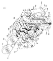
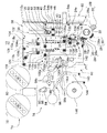
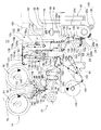
図1は、この発明にかかるラベル貼付装置の一例を示す斜視図解図である。図2は図1の正面図解図であり、図3は図2のA−A矢視図解図であり、図4は図1の平面図解図である。また、図5は、図1〜図4のラベル貼付装置に適用されるラベル貼付手段およびラベル供給手段の一例を示す斜視図解図であり、図6は図5の正面図解図であり、図7はその右側面図解図であり、図8はその底面図解図である。図9はこのラベル貼付装置におけるラベル連続体の移送経路を示す正面図解図であり、図10は図9の一部を拡大した正面図解図である。図11は、第1のラベル連続体および第2のラベル連続体の継ぎ構造を示す要部図解図である。図12は、トレーセンサ、高さ検知センサ、ラベル貼付センサおよびラベル発行センサの配置を示す正面図解図である。
ラベル貼付装置10は、図1〜図4に示すように、架台12を含む。架台12の上にはフレーム14が設けられる。フレーム14には、ラベル貼付手段16およびラベル供給手段18が配置される。
FIG. 1 is a perspective view illustrating an example of a label sticking device according to the present invention. 2 is a front schematic view of FIG. 1, FIG. 3 is an AA arrow view of FIG. 2, and FIG. 4 is a plan view of FIG. 5 is a perspective view illustrating an example of a label applying unit and a label supplying unit applied to the label applying apparatus of FIGS. 1 to 4, and FIG. 6 is a front view illustrating the FIG. Is a right side schematic view, and FIG. 8 is a bottom view. FIG. 9 is a front view solution diagram showing the transport path of the label continuum in this label sticking apparatus, and FIG. 10 is an enlarged front view solution view of a part of FIG. FIG. 11 is a main part illustrative view showing a joint structure of the first label continuous body and the second label continuous body. FIG. 12 is a front illustrative view showing the arrangement of the tray sensor, height detection sensor, label attaching sensor, and label issuing sensor.
The
ラベル貼付手段16およびラベル供給手段18の下方には、搬送手段として、たとえばコンベヤ部20が配置される。コンベヤ部20は、架台22の上に配置される。コンベヤ部20の搬送路には、その長手方向に所定の間隔を隔てて複数のトレーTが順次配列される。トレーTの上には、たとえば図2,図3に示すように、被貼付物として、メロン,トマト等の果物M(以下、「被貼付物M」という。)が載置される。被貼付物Mは、コンベヤ部20により、その搬送路の上流側から下流側に順次搬送され、ラベル貼付手段16の下方を通過し、さらに下流側に向かって搬送される。なお、本来は、全てのトレーTに被貼付物Mが載置されているが、便宜上、図1,図2,図4では、一部のトレーTにだけ被貼付物Mが載置されている状態を図示し、その他の被貼付物Mの図示を省略している。
Below the label sticking means 16 and the label supply means 18, for example, a
ラベル貼付手段16は、特に、たとえば図5〜図9に示すように、カバー24aを有する筐体24を含み、筐体24には、回転ヘッド26が配置される。回転ヘッド26は、筐体24に回動自在に支持される。この回転ヘッド26は、本願発明の背景となる従来のラベル貼り機が開示されている[特許文献1]に記載の回転ヘッドと同様の構造を有するため、ここでは回転ヘッド26自体の構造を示す詳細な図解図は省略して説明する。
すなわち、回転ヘッド26は、その周縁部にたとえば5つのラベル吸着保持具28を有し、5つのラベル吸着保持具28は、回転ヘッド26の放射線方向に向けて設けられる。ラベル吸着保持具28は、弾性ゴム等の弾性体からなる伸縮自在の蛇腹筒部28aを含む。蛇腹筒部28aは、その先端頂面部に蛇腹筒部28aの内部に連通する複数の吸引孔(図示せず)を備えたラベル吸着部30を有する。吸引孔の内面側には、逆止弁部(図示せず)が内蔵される。
In particular, as shown in FIGS. 5 to 9, for example, the label sticking means 16 includes a
That is, the
また、回転ヘッド26は、たとえば図6に示すように、空気吸引部(図示せず)および空気圧供給部(図示せず)を内蔵した軸部32が筐体24に回動自在に支持される。筐体24には、図5に示すように、サーボモータ等(図示せず)を含む駆動装置34が配置される。回転ヘッド26は、駆動装置34によって回転駆動され、その回転速度が調整される。空気吸引部(図示せず)および空気圧供給部(図示せず)を内蔵した軸部32と、回転ヘッド26とのまわり対偶部には、ロータリーバルブ(図示せず)が介在されていて、回転ヘッド26の回転にともなって、ラベル吸着保持具28と、空気吸引部および空気圧供給部との連通状態が切換えられる。
Further, for example, as shown in FIG. 6, the
この場合、回転ヘッド26の回転域上側の所定範囲では、ラベル吸着保持具28と空気吸引部(図示せず)とだけが連通してラベル吸着保持具28の内部が吸引状態に維持され、ラベル吸着部30にラベルが吸着可能となる。そして、ラベル吸着保持具28が下側に位置し、被貼付物Mにラベルを貼付する区間では、ラベル吸着保持具28と空気圧供給部(図示せず)とが連通してラベル吸着保持具28の内部が加圧状態となるため、蛇腹筒部28aが伸長可能となり、ラベル吸着部30に吸着されたラベルを被貼付物Mに貼付け可能となる。
なお、ラベル吸着保持具30の構成、および、回転ヘッド26とラベル吸着保持具28、ラベル吸着保持具28とロータリーバルブの組み合わせは既に知られた公知の構成である。
In this case, in a predetermined range above the rotation range of the
The configuration of the
ラベル貼付手段16の回転ヘッド26は、コンベヤ部20で搬送されてくる被貼付物Mの高さに応じて、被貼付物Mの高さ方向に変位可能に配置される。この場合、回転ヘッド26を支持している筐体24が、直動案内装置36によって、上下方向に往復直線運動自在に変位される。
直動案内装置36は、たとえば図5〜図9に示すように、フレーム38を含み、フレーム38には、2つのリニアガイドレール40が間隔を隔てて配置される。2つのリニアガイドレール40には、それぞれ、複数のリニア軸受部42により、可動テーブル44が2つのリニアガイドレール40に沿って直動可能に案内される。この場合、回転ヘッド26を支持している筐体24は、可動テーブル44の正面側にブラケット43により取付けられる。また、2つのリニア軸受部42は、可動テーブル44の裏面側で、その幅方向の両側に間隔を隔てて取付けられる。
The
As shown in FIGS. 5 to 9, for example, the linear
さらに、可動テーブル44の裏面側には、その幅方向の略中央に、ベアリングブロック45が配置される。このベアリングブロック45には、ボールねじ軸部46が回動自在に挿通される。ボールねじ軸部46は、その軸方向の一方側が軸受部48によりフレーム38に回動自在に支持され、その軸方向の他方側が軸受部48と同様の軸受部(図示せず)によりフレーム38に回動自在に支持される。ボールねじ軸部46は、その軸方向の一端部が、カップリング49を介して、サーボモータ50の駆動軸に接続される。そのため、ボールねじ軸部46は、たとえばサーボモータ50により回動自在に駆動される。サーボモータ50は、フレーム38の上にブラケットプレート52で固定されている。
Furthermore, a
また、フレーム38の側面には、図5,図6,図7等に示すように、可動テーブル44の可動範囲を検知して規制するための検知手段として、たとえばセンサ54a,54b,54cが配置される。センサ54aは、上下動する可動テーブル44の可動範囲の上限を検知し、センサ54cは、その下限を検知するためのものであり、センサ54bは、可動テーブル44の初期位置(原点位置)を検知し、可動テーブルを原点復帰させるためのものである。センサ54a〜54cには、それぞれ、たとえば透過形の光センサが用いられる。一方、可動テーブル44の上端側の一方の側面には、図5,図7,図8等に示すように、センサ54a,54b,54cの発光面と受光面との間を通過するドグプレート56が配置される。
Further, as shown in FIGS. 5, 6, 7, etc., for example,
上述した直動案内装置36を支持しているフレーム38は、ブラケット(図示せず)を含む適宜な取付手段(図示せず)により、図5〜図8に示すように、支持フレーム58に取付けられる。さらに、支持フレーム58は、取付ブラケット60により、たとえば図3に示すように、架台12に取付けられる。取付ブラケット60は、たとえば図5,図7に示すように、たとえば矩形状の取付プレート62を含み、取付プレート62は、その上部に円弧状の長孔62aを有し、取付プレート62の下部に取付フランジ64を有するものである。取付フランジ64は、複数の取付用孔64aを備え、取付プレート62の下端部に対して略直角に配置される。取付プレート62および取付フランジ64は一体的に形成される。
取付ブラケット60は、長孔62aを介して、ボルト等の固着手段66により、その取付プレートが支持フレーム58に取付けられ、取付用孔64aを介してボルト等の固着手段(図示せず)により取付フランジ64が架台12に取付けられる。この場合、長孔62aに対する固着手段66の配置を適宜変更することによって、支持フレーム58に対する取付ブラケット60の傾斜角度を変更することができる。つまり、支持フレーム58は、架台12に対して所定の傾斜角度で傾斜するように取付けることが可能となる。
The
The mounting
したがって、回転ヘッド26は、コンベヤ部20で搬送される被貼付物Mに対して、斜めに傾斜するように対向して配置させることができ、被貼付物Mの斜め上部にラベルを貼付することが可能となる。そのため、被貼付物Mがメロンやトマト等の果物のようにその頂点部に房の柄の部分が付いている場合でも、その柄の部分を外してラベルを貼付することができる。また、被貼付物Mの種類やその大きさが変更された場合でも、被貼付物Mに対する回転ヘッド26の傾斜角度は、架台12に対する支持フレーム58の取付け角度を変えることにより、適宜、変更することができる。
Therefore, the
次に、ラベル吸着保持具28のラベル吸着部30に単体のラベルを順次供給するラベル供給手段18について、図6および図9等を参照しながら説明する。
ラベル供給手段18は、剥離手段68を含む。剥離手段68は、剥離プレート70を含み、たとえば図9に示すように、ラベル連続体Rから単体のラベルrを剥離して、順次、ラベル吸着保持具28のラベル吸着部30に供給するためのものである。剥離プレート70に移送されたラベル連続体Rは、剥離プレート70のエッジ部70aの部分で折り返されてその移送方向が急激に変更されるため、ラベル連続体Rからラベルrが順次剥離され、剥離された単体のラベルrがラベル吸着部30に吸着される。
また、剥離手段68は、回転ヘッド26の近傍で回転ヘッド26とともに変位可能に配置される。すなわち、この剥離プレート70は、フレーム72により支持される。フレーム72は、ブラケット等(図示せず)により、上述した可動テーブル44に取付けられる。
Next, the label supply means 18 for sequentially supplying a single label to the
The
Further, the peeling means 68 is disposed so as to be displaceable together with the
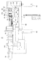
さらに、ラベル供給手段18は、剥離手段68の剥離プレート70に順次ラベル連続体Rを移送して案内するラベル連続体案内装置74を含む。そこで、ラベル連続体案内装置74について、たとえば図5,図6,図9,図10,図11を参照しながら説明する。
ラベル連続体案内装置74は、その表面に所定の間隔を隔てて多数のラベルrが配置される2つのラベル連続体R1,R2を接続するラベル連続体の継ぎ装置76を含む。継ぎ装置76は、間隔を隔てて配置される第1のワインダ78および第2のワインダ80を含む。第1のワインダ78および第2のワインダ80には、それぞれ、第1のラベル連続体R1および第2のラベル連続体R2がロール状に保持される。第1のラベル連続体R1および第2のラベル連続体R2は、それぞれ、たとえば帯状のセパレータからなる基材Sを含み、基材Sの表面には、所定の間隔を隔てて、ラベルrが配置される(図11参照)。第1のラベル連続体R1の終端側および第2のラベル連続体R2の始端側において、図11に示すように、それぞれ、その端面が基材Sの幅方向の側面に対して垂直な切断端面となるように切断されているものが用いられる。この場合、隣合うラベルrの間の略センタ位置で基材Sが切断される。
Further, the label supply means 18 includes a label
The label
このラベル連続体案内装置74では、たとえば図9に示すように、第1のワインダ78から繰り出された第1のラベル連続体R1が、テンションローラ等(図示せず)により一定の張力で下流側に案内され、ガイドローラ82により位置が規制されて下流側に案内される。そして、第1のラベル連続体R1は、ラベル連続体繰出し用駆動ベルト84に沿って、さらに下流側に案内される。この場合、ラベル連続体繰出し用駆動ベルト84は、フィードローラ86、テンションローラ88およびガイドローラ90に無端環状に掛け設けられる。フィードローラ86は、第1のワインダ78から第1のラベル連続体R1を繰り出すときに駆動力を付与するためのものである。テンションローラ88は、ラベル連続体繰出し用駆動ベルト84に所定の張力を付与し調整するものである。
In this label continuous
そして、第1のラベル連続体R1は、フィードローラ86およびピンチローラ92間に案内される。ピンチローラ92は、フィードローラ86に第1のラベル連続体R1を押し付けて、フィードローラ86と協働して第1のラベル連続体R1を繰出すときに駆動力を付与するためのものであり、枢軸部94により回動自在に支持されている。さらに、第1のラベル連続体R1は、ダンサローラユニット96へ移送される。ダンサローラユニット96は、たとえば2つのダンサローラ98aと2つのガイドローラ98bとを組合わせた構成となっている。このダンサローラユニット96は、2つのダンサローラ98aが上下動して、下流へ案内され走行する第1のラベル連続体R1の張力を一定に保持するためのものである。
The first label continuum R1 is guided between the
そして、第1のラベル連続体R1は、ダンサローラユニット96からテンションローラユニット100へと案内される。テンションローラユニット100は、ガイドローラ100aおよび送りローラ100bを有する。送りローラ100bの上側には、送りローラ100bと対向するように、ニップローラ100cが配置され、送りローラ100bの下側には、送りローラ100bと対向するように、ニップローラ100dが配置される。第1のラベル連続体R1は、ガイドローラ100aを介して、送りローラ100bおよびニップローラ100c間に移送された後、張力安定調整手段102へと案内される。
Then, the first label continuous body R1 is guided from the
張力安定調整手段102は、たとえば図5,図6,図9に示すように、ベースプレート104を含む。ベースプレート104は、その上下方向に所定の長さの長孔104a,104bを有する。ベースプレート104は、その背面側に配置された複数のブラケットバー105により支持フレーム58に支持される。ベースプレート104の正面側には、ガイドローラ106,108が配置される。また、ベースプレート104には、特に、図5および図6に示すように、その背面側で且つ長孔104a,104bの近傍に、それぞれ、固定ラック110a,110bが配置される。さらに、ベースプレート104には、特に、たとえば図6に示すように、固定ラック110a,110bと対向するようにして、可動ラック112a,112bが上下動自在に配置される。可動ラック112a,112bは、それぞれ、リニアガイドレール114a,114bに沿って直動自在に案内されるリニア軸受(図示せず)により支持される。
The tension stability adjusting means 102 includes a
さらに、固定ラック110aと可動ラック112aとの間、および、固定ラック110bと可動ラック112bとの間には、それぞれ、可動ピニオン116aおよび116bが配置される。可動ピニオン116aおよび116bには、それぞれ、フリーローラからなるガイドローラ118aおよび118bが取付けられる。この場合、ガイドローラ118aおよび118bは、ベースプレート104の正面側に突き出るように配置される。また、ベースプレート104の正面側には、ガイドローラ120,122,124が配置される。
Further,
また、可動ラック112a,112bを上下動自在に案内支持するリニアガイドレール114a,114bは、図6に示すように、それぞれ、支持シャフト126a,126bによりフレーム128に支持される。フレーム128には、その幅方向に間隔を隔てて、ガイドローラ130,132が配置される。フレーム128は、可動テーブル44に連結・固定される。
したがって、この張力安定調整手段102では、上下動する可動テーブル44に連動して、フレーム128が上下動自在となる。そのため、可動ラック112a,112bと共に可動ピニオン116a,116bが上下動する。このとき、可動ラック112a,112bに連動して、可動ピニオン116a,116bが固定ラック110a,110bに沿って回転運動を行なう。この場合、可動ラック112a,112bの上下方向の変位量に比べて、可動ピニオン116a,116bの固定ラック110a,110bに沿って変位する上下方向の変位量は小さいものとなる。そのため、可動ピニオン116a,116bの上下方向の変動量は、可動テーブル44の上下動の変動量、すなわち、回転ヘッド26の高さ方向(上下方向)の変動量に比べて、小さくすることができる。
Further, as shown in FIG. 6,
Therefore, in this tension stability adjusting means 102, the
張力安定調整手段102へと移送された第1のラベル連続体R1は、図9に示すように、ガイドローラ106,108を介してガイドローラ120に案内され、さらに、上下動自在のガイドローラ118aに案内されて、下流側のガイドローラ130へと移送される。そして、第1のラベル連続体R1は、フレーム72に配置されたガイドローラ134に案内され、ラベルセンサ136を通過した後、剥離プレート70へと移送される。
さらに、第1のラベル連続体R1は、剥離プレート70のエッジ部70aで移送方向が変更されてラベルrが順次剥離される。ラベルが剥離された第1のラベル連続体R1の基材Sは、ガイドローラ138へと移送される。第1のラベル連続体R1の基材Sは、ガイドローラ138を介して、ガイドローラ132へと案内され、張力安定調整手段102のガイドローラ118b,122,124へと案内される。
さらに、張力安定調整手段102から移送された第1のラベル連続体R1の基材Sは、テンションローラユニット100の送りローラ100bおよびニップローラ100d間に案内される。その後、第1のラベル連続体R1の基材Sは、テンションローラ140を介して、ガイドローラ142に案内され、さらに、テンションローラ144を介して、カス取りローラ146に巻き取られる。
As shown in FIG. 9, the first label continuum R1 transferred to the tension stability adjusting means 102 is guided to the
Further, in the first label continuous body R1, the transfer direction is changed at the
Further, the substrate S of the first label continuum R1 transferred from the tension stability adjusting means 102 is guided between the
上述のラベル連続体案内装置74では、張力安定調整手段102の作用により、回転ヘッド26の上下動によって、剥離プレート70へ案内される第1のラベル連続体R1にかかる張力、および、剥離プレート70で単体のラベルrが剥離された後の第1のラベル連続体R1の基材Sにかかる張力に対して、急激な変化を与えることがなく、それらの張力を一定にして安定させることが可能となる。このラベル連続体案内装置74では、張力安定調整手段が、固定ラック110a,110bと、可動ラック112a,112bと、固定ラック110a,110bおよび可動ラック112a,112b間に配置される可動ピニオン116a,116bとで、ダンサローラ部を構成している。
In the label
次に、ラベル連続体案内装置74のラベル連続体の継ぎ装置76における第1のラベル連続体R1と第2のラベル連続体R2とを継いで接続するための継ぎ構造について、たとえば図9,図10を参照しながら説明する。
第2のワインダ180から繰り出される第2のラベル連続体R2は、テンションローラ等(図示せず)により一定の張力で下流側に案内され、ガイドローラ148により位置が規制されて、下流側に案内される。第2のラベル連続体R2は、第1のラベル連続体R1の終端部に適宜継がれる待機用ラベル連続体として用いられる。
ガイドローラ82およびガイドローラ90の中間部で第1のラベル連続体R1が案内される案内経路近傍には、その内部を負圧(陰圧)とした第1のラベル連続体用吸着ボックス150が配設される。第1のラベル連続体用吸着ボックス150は、その一方面に多数の吸引孔(図示せず)を有し、吸引孔を有する面が第1のラベル連続体R1の一方主面側と対向するように配設される。第1のラベル連続体用吸着ボックス150は、第1のラベル連続体R1の一方主面を一旦吸着して保持し、且つ、第1のラベル連続体R1をラベル連続体繰出し用駆動ベルト84へと案内できるように構成される。
Next, a joint structure for joining and connecting the first label continuous body R1 and the second label continuous body R2 in the label continuous body
The second label continuum R2 fed out from the
In the vicinity of the guide path where the first label continuous body R1 is guided at an intermediate portion between the guide roller 82 and the
同様に、ガイドローラ148およびガイドローラ90の中間部で第2のラベル連続体R2が案内される案内経路近傍には、第2のラベル連続体用吸着ボックス152が配設される。第2のラベル連続体用吸着ボックス152は、吸引孔を有する面が第2のラベル連続体R2の他方主面側と対向するように配設される。第2のラベル連続体用吸着ボックス152は、第2のラベル連続体R2の他方主面を一旦吸着して保持し、且つ、第2のラベル連続体R2をラベル連続体繰出し用駆動ベルト84へと案内できるように構成される。
Similarly, a second label
第1のラベル連続体用吸着ボックス150および第2のラベル連続体用吸着ボックス152は、第1のラベル連続体R1の終端と第2のラベル連続体R2の始端とを突き合わせるときに、所定の位置に、第1のラベル連続体R1の終端と第2のラベル連続体R2の始端とを配置させ保持させるために用いられる。
The first label
また、第1のラベル連続体用吸着ボックス150の近傍には、第1のラベル連続体R1の案内経路を間に挟んで、第1のラベル連続体R1の他方主面側と対向するように、補助ガイド部材(図示せず)が下流側に所定の長さで配設される。同様に、第2のラベル連続体用吸着ボックス152の近傍にも、第2のラベル連続体R2の案内経路を間に挟んで、第2のラベル連続体R2の一方主面側と対向するように、補助ガイド部材(図示せず)が下流側に所定の長さで配設される。補助ガイド部材(図示せず)は、第1のラベル連続体R1および第2のラベル連続体R2を撓むことなく正確に、ガイドローラ90と後述する投入用ラベル押えローラ154との間に案内させるためのものである。
Further, in the vicinity of the first label continuous
また、第1のラベル連続体用吸着ボックス150の上流側で且つ第1のラベル連続体用吸着ボックス150の近傍には、第1のラベル連続体検知センサ156が配設され、第2のラベル連続体用吸着ボックス152の上流側で且つ第2のラベル連続体用吸着ボックス152の近傍には、第2のラベル連続体検知センサ158が配設される。第1のラベル連続体検知センサ156および第2のラベル連続体検知センサ158は、それぞれ、第1のラベル連続体R1および第2のラベル連続体R2を使用中に、第1のラベル連続体R1および第2のラベル連続体R2の終了を検知することができる。ラベル連続体検知センサとしてたとえば反射型の光センサが用いられる。
In addition, a first label
さらに、第1のラベル連続体用吸着ボックス150の下流側で且つ第1のラベル連続体用吸着ボックス150の近傍には、第1のラベル連続体位置決めセンサ160が配設され、第2のラベル連続体用吸着ボックス152の下流側で且つ第2のラベル連続体用吸着ボックス152の近傍には、第2のラベル連続体位置決めセンサ162が配設される。第1のラベル連続体位置決めセンサ160および第2のラベル連続体位置決めセンサ162は、第1のラベル連続体R1および第2のラベル連続体R2を継ぐときに、それぞれ、第1のラベル連続体R1および第2のラベル連続体R2の終了端の位置を検知するセンサであり、たとえば投光部および受光部を有する光センサが用いられる。
Further, a first label
また、ラベル連続体繰出し用駆動ベルト84の近傍には、ガイドローラ90と所定の間隔を隔てて対向配置されるように、投入用ラベル押えローラ154が配設される。投入用ラベル押えローラ154は、アクチュエータとしてのたとえば空気圧シリンダ164により、ガイドローラ90側に向けて往復直線運動可能に支持される。
In addition, a loading
この場合、投入用ラベル押えローラ154は、空気圧シリンダ164のピストンロッド164aの一端部に回動自在に支持される。投入用ラベル押えローラ154は、常時には、ガイドローラ90に押し付けられていない状態となっている。この投入用ラベル押えローラ154は、第1のラベル連続体R1と第2のラベル連続体R2とを継ぐときに、投入側の第2のラベル連続体R2を所定の突き合わせ位置に送り出すためのものである。つまり、投入用ラベル押えローラ154は、ガイドローラ90に第2のラベル連続体R2を押付けて、ガイドローラ90との協働作用により、第2のラベル連続体R2を所定の位置に送り出す機能を有する。
In this case, the loading
また、ガイドローラ90の下流側には、図10に示すように、ラベル連続体繰出し用駆動ベルト84と僅かな間隔を隔てて対向するように、他の補助ガイド部材166が所定の長さをもって配設される。この補助ガイド部材166は、ラベル連続体繰出し用駆動ベルト84を支持する支持プレート168と、所定の間隔を隔てて、対向配置される。補助ガイド部材166は、第1のラベル連続体R1および第2のラベル連続体R2をラベル連続体繰出し用駆動ベルト84に沿って、撓むことなく、下流側に案内させるためのものである。
Further, as shown in FIG. 10, another
さらに、ガイドローラ90の下流側には、第1のラベル連続体R1と第2のラベル連続体R2とを接続部材で継ぐことにより接続する接続部材付与手段170が配設される。接続部材付与手段170は、継ぎテープ連続体172をロール状に保持する保持ローラ174を含む。継ぎテープ連続体172は、帯状のセパレータ基材の一方主面に、多数のたとえば透明の継ぎテープが所定の間隔を隔てて配設されたものである。保持ローラ174から繰り出された継ぎテープ連続体172は、テンションローラ176により一定の張力で、ガイドローラ178を介して、ガイドローラ180および剥離器182の間に案内される。ガイドローラ180は、ラベル連続体繰出し用駆動ベルト84の近傍で、フィードローラ86と対向するように配置される。剥離器182の作用により、継ぎテープ連続体172から継ぎテープが剥離される。そして、剥離された継ぎテープは、ラベル連続体繰出し用駆動ベルト84側へと送り出される。
Further, on the downstream side of the
一方、継ぎテープが剥離された後の継ぎテープ連続体172の基材(以下、継ぎテープ連続体172のテープカスという。)は、特に、図10に示すように、ガイドローラ183により位置が規制されて、フィードローラ184およびピンチローラ186間に案内される。そして、継ぎテープ連続体172のテープカスは、適宜、テープカス蓄積ボックス(図示せず)等に排出される。フィードローラ184は、保持ローラ174から継ぎテープ連続体172を繰り出すときに駆動力を付与するためのものである。テンションローラ176は、継ぎテープ連続体172に所定の張力を付与し調整するものである。ピンチローラ186は、フィードローラ184に継ぎテープ連続体172のテープカスを押付け、フィードローラ184と協働して継ぎテープ連続体172を繰り出すときの駆動力を付与するためのものである。
なお、ラベル連続体繰出し用駆動ベルト84を回転駆動させるための回転駆動軸(図示せず)は、継ぎテープ連続体172を繰出すためのフィードローラ184を回転駆動させるための回転駆動軸(図示せず)として兼用されている。
On the other hand, the position of the base material of the
A rotation drive shaft (not shown) for rotating the label continuous body feeding
次に、第1のワインダ78から繰り出される第1のラベル連続体R1および第2のワインダ80から繰り出される第2のラベル連続体R2の継ぎ方法について、特に、たとえば図9,図10および図11等を参照しながら説明する。以下の説明では、第1のワインダ78から繰り出される第1のラベル連続体R1の使用が終了して、引き続き、その第1のラベル連続体R1の終端部と、第2のワインダ80から繰り出される第2のラベル連続体R2の始端部とを継ぎテープで継ぐ工程について説明する。
Next, the splicing method of the first label continuum R1 fed out from the
予め、待機用の第2のワインダ80から繰り出した第2のラベル連続体R2の始端側が、第2のラベル連続体用吸着ボックス152にセットされる。第2のラベル連続体R2の始端部は、図11に示すように、第1のワインダ78から繰り出された第1のラベル連続体R1の終端部と突き合わせることができるように、所定のセット位置に位置決めされる。この場合、所定のセット位置とは、投入用ラベル押えローラ154よりたとえば10mm程度、下に設定され、その位置に目印が付けられる。第2のワインダ80から繰り出される第2のラベル連続体R2の始端部は、目印の位置に配置されるように、第2のラベル連続体用吸着ボックス152にセットされる。このとき、投入用ラベル押えローラ154のピストンロッド164aは伸長しておらず、投入用ラベル押えローラ154はガイドローラ90に押し付けられた状態とはなっていない。
そして、第1のラベル連続体検知センサ158により、第1のワインダ78から繰り出された第1のラベル連続体R1の終了が検知されると、ラベル連続体繰出し用駆動ベルト84により、第1のラベル連続体R1が低速にて送られる。
The start side of the second label continuum R2 fed out from the
When the first label
さらに、第1のラベル連続体検知センサ158により、第1のラベル連続体R1の終端部が検知されると、予め、第2のラベル連続体R2の始端部がセットされている所定のセット位置に、第1のラベル連続体R1の終端部が送られる。そして、第2のラベル連続体R2は、投入用ラベル押えローラ154によって、ラベル連続体繰出し用駆動ベルト84側、つまり、ガイドローラ90に押付けられる。このとき、第1のラベル連続体R1の終端部と第2のラベル連続体R2の始端部とが、所定のセット位置Jで突き合わせられる(図11参照。)
Further, when the first label
さらに、それとほぼ同時に、第2のラベル連続体R2は、第1のラベル連続体R1と共に、第1のラベル連続体R1と同速にて、下流側に送られる。そして、下流側に送られた第1のラベル連続体R1および第2のラベル連続体R2は、図11に示すように、第1のラベル連続体R1の終端部および第2のラベル連続体R2の始端部の突き合せ端部Jが、剥離器182で剥離された継ぎテープ188によって接続される。この場合、第1のラベル連続体R1および第2のラベル連続体R2の突き合せ端部Jは、ガイドローラ180および剥離器182の協働作用によって、第1のラベル連続体R1および第2のラベル連続体R2の裏面側から、突き合せ端部J部分を覆うようにして、継ぎテープ188で継がれる。
Furthermore, almost simultaneously with this, the second label continuum R2 is sent downstream along with the first label continuum R1 at the same speed as the first label continuum R1. Then, the first label continuum R1 and the second label continuum R2 sent to the downstream side are, as shown in FIG. 11, the end portion of the first label continuum R1 and the second label continuum R2. The butt end portion J of the start end portion is connected by the
この場合、突き合わせ端部J部分が継ぎテープ188で継がれた第1のラベル連続体R1および第2のラベル連続体R2の表面側には、段差部が形成されない。そして、継ぎテープ188は、第1のラベル連続体R1および第2のラベル連続体R2の裏面側に取付けられるため、第1のラベル連続体R1および第2のラベル連続体R2の表面側には、予め余白部分を設ける必要がない。
したがって、上述したラベル連続体の継ぎ装置76では、接続部分に段差が生じることなく、無駄なく、2つのラベル連続体R1,R2を自動的に継ぐことができ、ランニングコストの低減化も図れる。
なお、上述した第1のラベル連続体R1および第2のラベル連続体R2の継ぎ方法では、第2のラベル連続体R2を待機用として用い、第1のラベル連続体R1の終端部に第2のラベル連続体R2の始端部を突き合わせるようにしたが、逆に、第1のラベル連続体R1を待機用として用い、第2のラベル連続体R2の終端部に第1のラベル連続体R1の始端部を突き合わせるようにしてもよい。
In this case, no stepped portion is formed on the surface side of the first label continuum R1 and the second label continuum R2 where the butted end portion J is joined by the joining
Therefore, the above-described label continuous
In the above-described joining method of the first label continuum R1 and the second label continuum R2, the second label continuum R2 is used for standby, and the second label continuum R2 is used as the second end of the first label continuum R1. However, the first label continuum R1 is used for standby, and the first label continuum R1 is used as the end of the second label continuum R2. You may make it abut the start part of.
次に、駆動装置34を制御し、回転ヘッド26の下方に被貼付物Mが搬送されたとき、コンベヤ部20により搬送される被貼付物Mの動作に同期するようにしてラベル吸着保持具28を伸長させた状態で回転させ、タイミングよく被貼付物Mにラベルを貼付させるための制御手段について説明する。
すなわち、ラベル貼付装置10は、制御手段190を含み、制御手段190は、図1,図2,図4等に示すように、コンベヤ部20を間に挟んで、ラベル貼付手段16およびラベル供給手段18とは、反対側に配置される。回転ヘッド26を駆動させる駆動装置34のサーボモータ(図示せず)は、制御手段190によって適宜制御される。
Next, the
That is, the
また、ラベル貼付装置10は、特に、たとえば図12に示すように、被貼付物Mの通過を検知する通過検知手段として、たとえばコンベヤ部20に配列されたトレーTの位置を検知するトレーセンサ192を含む。トレーセンサ192は、回転ヘッド26の真下よりも上流側のコンベヤ部20の搬送路近傍に配置され、トレーTの前端部と後端部とを検知して、トレーTが通過したことを検知するためのものである。トレーセンサ192としては、たとえばミラー反射形の光センサが用いられる。
In addition, the
さらに、ラベル貼付装置10は、被貼付物Mの高さを検知するための高さ検知手段として、たとえば高さ検知センサ194を含む。高さ検知センサ194は、コンベヤ部20の搬送路近傍に、たとえばトレーセンサ192の上方に配置される。高さ検知センサ194は、トレーセンサ192により1つのトレーTの通過が検知されている間に、そのトレーTに載置された被貼付物Mの高さを検知するためのものである。高さ検知センサ194としては、たとえば拡散反射形の光センサが用いられる。高さ検知センサ194で検知された被貼付物Mの高さに応じて、回転ヘッド26がその上下方向に変位する。この場合、制御手段190は、高さ検知センサ194からの検知信号を受けて、回転ヘッド26を上下方向に変位させるサーボモータ50を駆動させる。
Furthermore, the
さらに、ラベル貼付装置10は、ラベル貼付センサ196を含む。ラベル貼付センサ196は、回転ヘッド26の真下よりも僅かに上流側の搬送路近傍に配置される。ラベル貼付センサ196としては、たとえばミラー反射形の光センサが用いられる。ラベル貼付センサ196は、1つのトレーTの検知範囲内で、被貼付物Mの適当な位置にラベルを貼付する指示を出すためのものである。この場合、制御手段190は、ラベル貼付センサ196からの検知信号を受けて、回転ヘッド26を回転させて、ラベルを被貼付物Mに貼付させる回転ヘッド26の駆動装置34を駆動させる。なお、図12では、回転ヘッド26が図12中最も高い被貼付物Mにラベルを貼付した直後の状態を示している。
Furthermore, the
さらに、ラベル貼付装置10は、ラベル発行センサ198を含む。ラベル発行センサ198は、駆動装置34に内蔵される。この場合、制御手段190は、ラベル発行センサ198からの検知信号を受けて、回転ヘッド26において待機中のラベル吸着部30に順次ラベルを吸着させるように、回転ヘッド26の駆動装置34を駆動させる。
Further, the
なお、回転ヘッド26を回転駆動させ、回転ヘッド26の回転速度を調整する駆動装置34については、本願発明の背景となる従来のラベル貼り機が開示されている[特許文献1]に記載の駆動装置と同様の作用・効果を有するため、その詳細な説明は省略する。
As for the
このラベル貼付装置10では、回転ヘッド26が高さ検知センサ194により検知され、さらに、高さ検知センサ194の検知信号を受けて、制御手段190が回転ヘッド26を上下動させるサーボモータ50を駆動させるため、コンベヤ部20に高さが異なる被貼付物Mが順次搬送された場合でも、被貼付物Mの高さに対応して、被貼付物Mにラベルを正確に貼付することができる。
In this
この発明にかかるラベル貼付装置は、特に、高さの異なる果物その他の被貼付物にラベルを高速で且つ連続的に貼付するのに好適なラベル貼付装置である。 The label applicator according to the present invention is a label applicator that is particularly suitable for applying labels at high speed and continuously to fruits and other objects to be attached having different heights.
10 ラベル貼付装置
16 ラベル貼付手段
18 ラベル供給手段
20 コンベヤ部
26 回転ヘッド
28 ラベル吸着保持具
30 ラベル吸着部
34 駆動装置
36 直動案内装置
50 サーボモータ
68 剥離手段
70 剥離プレート
74 ラベル連続体案内装置
76 ラベル連続体の継ぎ装置
102 張力安定調整手段
110a,110b 固定ラック
112a,112b 可動ラック
116a,116b 可動ピニオン
R1 第1のラベル連続体
R2 第2のラベル連続体
170 接続部材付与手段
172 継ぎテープ連続体
188 継ぎテープ
190 制御手段
192 トレーセンサ
194 高さ検知センサ
196 ラベル貼付センサ
198 ラベル発行センサ
M 被貼付物
T トレー
DESCRIPTION OF
Claims (2)
前記搬送手段の上流側搬送路の近傍に配置され、前記被貼付物の通過を検知するための通過検知手段、
前記搬送手段の上流側搬送路の近傍に配置され、前記通過検知手段により1つの前記被貼付物が検知されている間に、前記被貼付物の高さを検知するための高さ検知手段、および
前記搬送手段の下流側搬送路の上方に配置され、前記被貼付物に順次ラベルを貼付するためのラベル貼付手段を含み、
前記ラベル貼付手段は、
その周囲に伸縮自在の複数のラベル吸着保持具が設けられ、その下方に前記被貼付物が搬送されたとき、1つの前記ラベル吸着保持具を伸長させて前記被貼付物に順次前記ラベルを貼付させるための回転ヘッド、
前記回転ヘッドを回転駆動させ、前記回転ヘッドの回転速度を調整する駆動装置、および
前記駆動装置を制御し、前記回転ヘッドの下方に前記被貼付物が搬送されたとき、前記搬送手段により搬送される前記被貼付物の動作に同期するようにして前記ラベル吸着保持具を伸長させた状態で回転させ、タイミングよく前記被貼付物に前記ラベルを貼付させるための制御手段を含み、
前記回転ヘッドは、前記高さ検知手段により検知された前記被貼付物の高さに応じて前記高さ方向に変位可能に配置されるラベル貼付装置であって、
前記ラベル吸着保持具の先端部にラベルを順次供給するラベル供給手段をさらに含み、
前記ラベル供給手段は、
前記回転ヘッドの近傍で前記回転ヘッドとともに変位可能に配置され、ラベル連続体からラベルを剥離して順次ラベル吸着保持具の先端部に供給するための剥離手段、および
前記回転ヘッドが前記高さ方向に変位したとき、前記剥離手段へ案内される前記ラベル連続体の張力と、前記剥離手段で前記ラベルが剥離された後の前記ラベル連続体の基材の張力とに、悪影響を与えないようにするための張力安定調整手段を含み、
前記張力安定調整手段は、2組の固定ラックと可動ラックとの間にそれぞれ配置した可動ピニオンに取付けられたガイドローラを含み、前記ラベル連続体および前記ラベルが剥離された後の前記ラベル連続体の基材がそれぞれ別個の前記ガイドローラに案内されてなり、前記回転ヘッドの前記高さ方向への変位に連動して、前記可動ラックに往復直線運動を付与することを特徴とする、ラベル貼付装置。 Conveying means for sequentially conveying the objects to be stuck arranged in the conveying path at intervals from the upstream side to the downstream side,
A passage detecting means disposed in the vicinity of the upstream conveying path of the conveying means for detecting the passage of the object to be pasted,
A height detection means for detecting the height of the object to be pasted while the one of the objects to be pasted is being detected by the passage detection means, which is disposed in the vicinity of the upstream conveying path of the transport means; And a label affixing unit that is disposed above a conveyance path on the downstream side of the conveying unit and sequentially affixes a label to the object to be adhered,
The label attaching means is
A plurality of retractable label suction holders are provided around it, and when the adherend is transported below, one label suction holder is extended and the labels are sequentially attached to the adherend. Rotating head, for
A driving device that rotates the rotating head and adjusts the rotational speed of the rotating head; and controls the driving device, and when the adherend is transported below the rotating head, the material is transported by the transporting means. The label suction holder is rotated in an extended state so as to be synchronized with the operation of the object to be pasted, and includes a control means for causing the label to be affixed to the object to be pasted in a timely manner.
The rotating head is a label sticking device arranged to be displaceable in the height direction according to the height of the object to be stuck detected by the height detecting means ,
Further comprising label supply means for sequentially supplying labels to the tip of the label suction holder,
The label supply means includes
A peeling means that is displaceably disposed with the rotary head in the vicinity of the rotary head, for peeling off the label from the label continuum and sequentially supplying it to the tip of the label suction holder; and
When the rotary head is displaced in the height direction, the tension of the label continuum guided to the peeling means and the tension of the base material of the label continuum after the label is peeled by the peeling means Includes a tension stabilization adjusting means for preventing adverse effects,
The tension stability adjusting means includes guide rollers attached to movable pinions respectively arranged between two sets of fixed racks and movable racks, and the label continuum and the label continuum after the label is peeled off. Each of the substrates is guided by the separate guide rollers, and reciprocating linear motion is imparted to the movable rack in conjunction with the displacement of the rotary head in the height direction. apparatus.
前記継ぎ装置は、
一方の前記ラベル連続体の終端と他方の前記ラベル連続体の始端とを突き合わせる突き合わせ手段、および
前記一方のラベル連続体および前記他方のラベル連続体の裏面側から、前記一方のラベル連続体と前記他方のラベル連続体との突き合わせ端部を覆うようにして、前記一方のラベル連続体および前記他方のラベル連続体の裏面に接続部材を取付ける接続部材付与手段を含む、請求項1に記載のラベル貼付装置。 The label supply means further includes a label continuum splicing device for connecting two label continuums on the surface of which a plurality of labels are arranged at predetermined intervals.
The splicing device is
Abutting means for abutting the end of one of the label continuum and the start of the other label continuum; and from the back side of the one label continuum and the other label continuum, The connection member provision means which attaches a connection member to the back of the one label continuum and the other label continuation so as to cover the abutting end with the other label continuum, according to claim 1 . Labeling device.
Priority Applications (1)
| Application Number | Priority Date | Filing Date | Title |
|---|---|---|---|
| JP2003341891A JP4366166B2 (en) | 2003-09-30 | 2003-09-30 | Labeling device |
Applications Claiming Priority (1)
| Application Number | Priority Date | Filing Date | Title |
|---|---|---|---|
| JP2003341891A JP4366166B2 (en) | 2003-09-30 | 2003-09-30 | Labeling device |
Publications (2)
| Publication Number | Publication Date |
|---|---|
| JP2005104543A JP2005104543A (en) | 2005-04-21 |
| JP4366166B2 true JP4366166B2 (en) | 2009-11-18 |
Family
ID=34536338
Family Applications (1)
| Application Number | Title | Priority Date | Filing Date |
|---|---|---|---|
| JP2003341891A Expired - Fee Related JP4366166B2 (en) | 2003-09-30 | 2003-09-30 | Labeling device |
Country Status (1)
| Country | Link |
|---|---|
| JP (1) | JP4366166B2 (en) |
Families Citing this family (7)
| Publication number | Priority date | Publication date | Assignee | Title |
|---|---|---|---|---|
| KR100747982B1 (en) | 2006-07-19 | 2007-08-08 | 현대제철 주식회사 | System of attaching a label of a steel |
| JP5022851B2 (en) * | 2007-09-29 | 2012-09-12 | 株式会社サトー知識財産研究所 | Labeling system |
| JP5276333B2 (en) * | 2008-01-31 | 2013-08-28 | サトーホールディングス株式会社 | Labeling device |
| JP5356917B2 (en) * | 2009-05-29 | 2013-12-04 | リンテック株式会社 | Sheet pasting device |
| CN101927849B (en) * | 2009-06-18 | 2013-07-17 | 四川科伦药业股份有限公司 | Control system of miniature labeling machine |
| DE102012207366A1 (en) * | 2012-05-03 | 2013-11-07 | Krones Ag | Method for attaching sticking labels at front side such as top face of closure cap of container, involves carrying peeled labels along transport path, where sticking face is faced downward corresponding to front side |
| CN115308228B (en) * | 2022-08-05 | 2023-04-25 | 深圳市俱进纸品包装有限公司 | Visual inspection device for printed label production system |
-
2003
- 2003-09-30 JP JP2003341891A patent/JP4366166B2/en not_active Expired - Fee Related
Also Published As
| Publication number | Publication date |
|---|---|
| JP2005104543A (en) | 2005-04-21 |
Similar Documents
| Publication | Publication Date | Title |
|---|---|---|
| JP4340788B2 (en) | Polarizer pasting device to substrate | |
| JP4366166B2 (en) | Labeling device | |
| JP4699720B2 (en) | Pasting device and pasting method | |
| JP4767198B2 (en) | Tack labeler | |
| JPH05207B2 (en) | ||
| JP4791174B2 (en) | Label sticking device and label sticking method | |
| JP5412671B2 (en) | Film part cutting device | |
| JP2006193169A (en) | Labelling device | |
| JPH0699957A (en) | Device for affixing label | |
| JP3370722B2 (en) | Label sticking device | |
| JP4448689B2 (en) | Labeling device | |
| JP5800521B2 (en) | Labeling device | |
| JP2007238160A (en) | Tack labeler | |
| JP6339656B2 (en) | Labeling device | |
| JP2019073325A (en) | Sheet feeder and sheet feeding method | |
| JP3867936B2 (en) | Method and apparatus for connecting strip material | |
| JP2002145229A (en) | Label affixing machine | |
| JP3982858B2 (en) | Leading-out device for strip material | |
| JP6087091B2 (en) | Labeling device | |
| JPH0115627Y2 (en) | ||
| JP2002301687A (en) | Film supplying device | |
| JP2009149429A (en) | Peeling method for sheet-shaped component, component supply device and component supply system | |
| CN212354675U (en) | Label feeding mechanism in labeling machine | |
| JP3713567B2 (en) | Roll body supply device | |
| CN110789142B (en) | Conveying device and bonding equipment |
Legal Events
| Date | Code | Title | Description |
|---|---|---|---|
| A621 | Written request for application examination |
Free format text: JAPANESE INTERMEDIATE CODE: A621 Effective date: 20060828 |
|
| A977 | Report on retrieval |
Free format text: JAPANESE INTERMEDIATE CODE: A971007 Effective date: 20090522 |
|
| A131 | Notification of reasons for refusal |
Free format text: JAPANESE INTERMEDIATE CODE: A131 Effective date: 20090526 |
|
| A521 | Request for written amendment filed |
Free format text: JAPANESE INTERMEDIATE CODE: A523 Effective date: 20090723 |
|
| RD02 | Notification of acceptance of power of attorney |
Free format text: JAPANESE INTERMEDIATE CODE: A7422 Effective date: 20090723 |
|
| TRDD | Decision of grant or rejection written | ||
| A01 | Written decision to grant a patent or to grant a registration (utility model) |
Free format text: JAPANESE INTERMEDIATE CODE: A01 Effective date: 20090818 |
|
| A01 | Written decision to grant a patent or to grant a registration (utility model) |
Free format text: JAPANESE INTERMEDIATE CODE: A01 |
|
| A61 | First payment of annual fees (during grant procedure) |
Free format text: JAPANESE INTERMEDIATE CODE: A61 Effective date: 20090824 |
|
| FPAY | Renewal fee payment (event date is renewal date of database) |
Free format text: PAYMENT UNTIL: 20120828 Year of fee payment: 3 |
|
| R150 | Certificate of patent or registration of utility model |
Free format text: JAPANESE INTERMEDIATE CODE: R150 Ref document number: 4366166 Country of ref document: JP Free format text: JAPANESE INTERMEDIATE CODE: R150 |
|
| FPAY | Renewal fee payment (event date is renewal date of database) |
Free format text: PAYMENT UNTIL: 20120828 Year of fee payment: 3 |
|
| FPAY | Renewal fee payment (event date is renewal date of database) |
Free format text: PAYMENT UNTIL: 20150828 Year of fee payment: 6 |
|
| R250 | Receipt of annual fees |
Free format text: JAPANESE INTERMEDIATE CODE: R250 |
|
| R250 | Receipt of annual fees |
Free format text: JAPANESE INTERMEDIATE CODE: R250 |
|
| R250 | Receipt of annual fees |
Free format text: JAPANESE INTERMEDIATE CODE: R250 |
|
| R250 | Receipt of annual fees |
Free format text: JAPANESE INTERMEDIATE CODE: R250 |
|
| R250 | Receipt of annual fees |
Free format text: JAPANESE INTERMEDIATE CODE: R250 |
|
| LAPS | Cancellation because of no payment of annual fees |