JP4366162B2 - Image forming apparatus - Google Patents
Image forming apparatus Download PDFInfo
- Publication number
- JP4366162B2 JP4366162B2 JP2003329180A JP2003329180A JP4366162B2 JP 4366162 B2 JP4366162 B2 JP 4366162B2 JP 2003329180 A JP2003329180 A JP 2003329180A JP 2003329180 A JP2003329180 A JP 2003329180A JP 4366162 B2 JP4366162 B2 JP 4366162B2
- Authority
- JP
- Japan
- Prior art keywords
- belt body
- belt
- roller
- image forming
- contact
- Prior art date
- Legal status (The legal status is an assumption and is not a legal conclusion. Google has not performed a legal analysis and makes no representation as to the accuracy of the status listed.)
- Expired - Fee Related
Links
Images


Classifications
-
- G—PHYSICS
- G03—PHOTOGRAPHY; CINEMATOGRAPHY; ANALOGOUS TECHNIQUES USING WAVES OTHER THAN OPTICAL WAVES; ELECTROGRAPHY; HOLOGRAPHY
- G03G—ELECTROGRAPHY; ELECTROPHOTOGRAPHY; MAGNETOGRAPHY
- G03G21/00—Arrangements not provided for by groups G03G13/00 - G03G19/00, e.g. cleaning, elimination of residual charge
- G03G21/16—Mechanical means for facilitating the maintenance of the apparatus, e.g. modular arrangements
- G03G21/1642—Mechanical means for facilitating the maintenance of the apparatus, e.g. modular arrangements for connecting the different parts of the apparatus
- G03G21/1647—Mechanical connection means
-
- G—PHYSICS
- G03—PHOTOGRAPHY; CINEMATOGRAPHY; ANALOGOUS TECHNIQUES USING WAVES OTHER THAN OPTICAL WAVES; ELECTROGRAPHY; HOLOGRAPHY
- G03G—ELECTROGRAPHY; ELECTROPHOTOGRAPHY; MAGNETOGRAPHY
- G03G15/00—Apparatus for electrographic processes using a charge pattern
-
- G—PHYSICS
- G03—PHOTOGRAPHY; CINEMATOGRAPHY; ANALOGOUS TECHNIQUES USING WAVES OTHER THAN OPTICAL WAVES; ELECTROGRAPHY; HOLOGRAPHY
- G03G—ELECTROGRAPHY; ELECTROPHOTOGRAPHY; MAGNETOGRAPHY
- G03G15/00—Apparatus for electrographic processes using a charge pattern
- G03G15/14—Apparatus for electrographic processes using a charge pattern for transferring a pattern to a second base
- G03G15/16—Apparatus for electrographic processes using a charge pattern for transferring a pattern to a second base of a toner pattern, e.g. a powder pattern, e.g. magnetic transfer
- G03G15/1605—Apparatus for electrographic processes using a charge pattern for transferring a pattern to a second base of a toner pattern, e.g. a powder pattern, e.g. magnetic transfer using at least one intermediate support
- G03G15/1615—Apparatus for electrographic processes using a charge pattern for transferring a pattern to a second base of a toner pattern, e.g. a powder pattern, e.g. magnetic transfer using at least one intermediate support relating to the driving mechanism for the intermediate support, e.g. gears, couplings, belt tensioning
-
- G—PHYSICS
- G03—PHOTOGRAPHY; CINEMATOGRAPHY; ANALOGOUS TECHNIQUES USING WAVES OTHER THAN OPTICAL WAVES; ELECTROGRAPHY; HOLOGRAPHY
- G03G—ELECTROGRAPHY; ELECTROPHOTOGRAPHY; MAGNETOGRAPHY
- G03G21/00—Arrangements not provided for by groups G03G13/00 - G03G19/00, e.g. cleaning, elimination of residual charge
- G03G21/16—Mechanical means for facilitating the maintenance of the apparatus, e.g. modular arrangements
- G03G21/1661—Mechanical means for facilitating the maintenance of the apparatus, e.g. modular arrangements means for handling parts of the apparatus in the apparatus
- G03G21/168—Mechanical means for facilitating the maintenance of the apparatus, e.g. modular arrangements means for handling parts of the apparatus in the apparatus for the transfer unit
-
- G—PHYSICS
- G03—PHOTOGRAPHY; CINEMATOGRAPHY; ANALOGOUS TECHNIQUES USING WAVES OTHER THAN OPTICAL WAVES; ELECTROGRAPHY; HOLOGRAPHY
- G03G—ELECTROGRAPHY; ELECTROPHOTOGRAPHY; MAGNETOGRAPHY
- G03G2215/00—Apparatus for electrophotographic processes
- G03G2215/00135—Handling of parts of the apparatus
- G03G2215/00139—Belt
-
- G—PHYSICS
- G03—PHOTOGRAPHY; CINEMATOGRAPHY; ANALOGOUS TECHNIQUES USING WAVES OTHER THAN OPTICAL WAVES; ELECTROGRAPHY; HOLOGRAPHY
- G03G—ELECTROGRAPHY; ELECTROPHOTOGRAPHY; MAGNETOGRAPHY
- G03G2215/00—Apparatus for electrophotographic processes
- G03G2215/01—Apparatus for electrophotographic processes for producing multicoloured copies
- G03G2215/0103—Plural electrographic recording members
- G03G2215/0119—Linear arrangement adjacent plural transfer points
- G03G2215/0122—Linear arrangement adjacent plural transfer points primary transfer to an intermediate transfer belt
- G03G2215/0135—Linear arrangement adjacent plural transfer points primary transfer to an intermediate transfer belt the linear arrangement being vertical
-
- G—PHYSICS
- G03—PHOTOGRAPHY; CINEMATOGRAPHY; ANALOGOUS TECHNIQUES USING WAVES OTHER THAN OPTICAL WAVES; ELECTROGRAPHY; HOLOGRAPHY
- G03G—ELECTROGRAPHY; ELECTROPHOTOGRAPHY; MAGNETOGRAPHY
- G03G2215/00—Apparatus for electrophotographic processes
- G03G2215/01—Apparatus for electrophotographic processes for producing multicoloured copies
- G03G2215/0103—Plural electrographic recording members
- G03G2215/0119—Linear arrangement adjacent plural transfer points
- G03G2215/0138—Linear arrangement adjacent plural transfer points primary transfer to a recording medium carried by a transport belt
- G03G2215/0141—Linear arrangement adjacent plural transfer points primary transfer to a recording medium carried by a transport belt the linear arrangement being horizontal
-
- G—PHYSICS
- G03—PHOTOGRAPHY; CINEMATOGRAPHY; ANALOGOUS TECHNIQUES USING WAVES OTHER THAN OPTICAL WAVES; ELECTROGRAPHY; HOLOGRAPHY
- G03G—ELECTROGRAPHY; ELECTROPHOTOGRAPHY; MAGNETOGRAPHY
- G03G2221/00—Processes not provided for by group G03G2215/00, e.g. cleaning or residual charge elimination
- G03G2221/16—Mechanical means for facilitating the maintenance of the apparatus, e.g. modular arrangements and complete machine concepts
- G03G2221/1642—Mechanical means for facilitating the maintenance of the apparatus, e.g. modular arrangements and complete machine concepts for the transfer unit
Description
本発明は、プリンタ、複写機などの電子写真方式或いは静電記録方式を利用した画像形成装置に関し、より詳細には、像担持体上のトナー像を転写材に転写するためのベルト体を備える画像形成装置に関するものである。 The present invention relates to an image forming apparatus using an electrophotographic system or an electrostatic recording system, such as a printer or a copying machine, and more specifically, includes a belt body for transferring a toner image on an image carrier onto a transfer material. The present invention relates to an image forming apparatus.
従来、画像形成プロセスに電子写真方式や静電気録方式を採用した種々の型式の画像形成装置がある。これら各種型式の画像形成装置の中には、プリンタ、複写機として広く使用されている、像担持体として感光ドラムを使用し、この感光ドラムの周辺に帯電手段、露光手段、現像手段などのプロセス手段を配し、更に転写機構、転写材搬送機構、定着機構などを配設した型式のものがある。 Conventionally, there are various types of image forming apparatuses that employ an electrophotographic system or an electrostatic recording system in an image forming process. Among these various types of image forming apparatuses, photosensitive drums are widely used as printers and copying machines, and photosensitive drums are used as image carriers, and processes such as charging means, exposure means, and developing means are provided around the photosensitive drums. There is a type that is provided with means and further provided with a transfer mechanism, a transfer material transport mechanism, a fixing mechanism, and the like.
そして、このような画像形成装置において、像担持体上のトナー像を転写材に転写するためのベルト体、即ち、像担持体から転写されるトナー像を担持する中間転写体(中間転写ベルト)、或いは像担持体からのトナー像を転写する転写材を担持して搬送する転写材搬送手段(転写材搬送ベルト)を採用した画像形成装置がある。 In such an image forming apparatus, a belt body for transferring a toner image on an image carrier to a transfer material, that is, an intermediate transfer body (intermediate transfer belt) carrying a toner image transferred from the image carrier. Alternatively, there is an image forming apparatus that employs a transfer material conveyance means (transfer material conveyance belt) that carries and conveys a transfer material for transferring a toner image from an image carrier.
ベルト体を備える画像形成装置では、ベルト機構に特有の駆動時のベルト体の寄り(片寄り)の発生を抑制する必要がある。ベルト体の寄りを補正するためには、従来、以下のような方法が採られていた。 In an image forming apparatus provided with a belt body, it is necessary to suppress the occurrence of deviation (one side deviation) of the belt body during driving, which is characteristic of the belt mechanism. In order to correct the deviation of the belt body, conventionally, the following method has been adopted.
(1)ベルト体は、通常、複数の張架部材として駆動ローラを含む複数のローラに張設されるが、ベルト体はローラ径の大きい方に寄ろうとする性質を持っている。そこで、この性質を利用して、ベルト体を張架するベルト張架装置において、ローラの直径を端部に比べ中央部を太くするとことにより、ベルト体の搬送方向に対して略直交方向(幅方向)の位置を制御(調心)する。 (1) The belt body is usually stretched around a plurality of rollers including a driving roller as a plurality of stretching members, but the belt body has a property of moving toward the larger roller diameter. Therefore, by utilizing this property, in a belt stretching device that stretches the belt body, the diameter of the roller is made thicker at the center than at the end, so that the direction substantially perpendicular to the belt body conveyance direction (width) Control (alignment) position.
(2)又は、各ローラの精度、平行度及びベルト体の精度を厳しく管理することにより、ベルト体の寄り速度を小さくした上で、ベルト体にリブを設けて、更にこのリブを規制するリブ規制部材を設けて、リブをベルト体の搬送方向(周回移動方向)に対し略直交方向、即ち、幅方向に規制することによってベルト体の寄りを規制していた。 (2) Or, by strictly controlling the accuracy and parallelism of each roller and the accuracy of the belt body, the belt body is provided with ribs on the belt body, and the rib body is further regulated by regulating the ribs. A regulating member is provided and the rib is regulated in a direction substantially orthogonal to the belt body conveyance direction (circumferential movement direction), that is, in the width direction, thereby restricting the belt body.
(3)更には、上記のように各ローラの精度等を厳しく管理し、又ベルト体に設けたリブでベルト体の寄りを規制した上で、ベルト張架装置を組み立てる際にベルト体の寄り傾向を測定し、それを打ち消すようにローラの平行度を調整する。 (3) Furthermore, as described above, the accuracy of each roller is strictly controlled, and the belt body is regulated by the ribs provided on the belt body, and the belt body is displaced when the belt stretching device is assembled. Measure the trend and adjust the roller parallelism to cancel it.
しかしながら、上記(1)のように、ローラの中央部を膨らませることでベルト体の調心を行う場合、ベルト体に十分な伸縮性がないと、ローラ径の細い部分にかかっている部分のベルト体が弛んでしまったり、調心そのものが正しく行われなかったりすることがある。又、ベルト体が非常に薄い場合、ベルト体自身が中央に寄ろうとする力に負けて、中央部において皺になるという問題が発生することがあった。 However, as described in (1) above, when the belt body is aligned by inflating the central part of the roller, if the belt body does not have sufficient stretchability, The belt body may become slack or the alignment itself may not be performed correctly. Further, when the belt body is very thin, there is a problem that the belt body itself loses the force to approach the center and becomes wrinkled at the center portion.
又、上記(2)のように、各ローラの精度等を厳しく管理し、ベルト体に設けたリブをベルト体の幅方向に規制することでベルト体の寄りを規制する方法においては、ベルト体の寄り傾向を完全に無くすことはできず、長時間使用する間に徐々にリブにストレスがたまり、ついにはリブ規制部材を乗り越え、ベルト体及び/又はリブの破損に至ることがあった。その上、斯かる方法では、高精度を要求されるため、部品のコストが高くなる。 Further, as described in (2) above, in the method of strictly controlling the accuracy of each roller and regulating the deviation of the belt body by regulating the rib provided on the belt body in the width direction of the belt body, The tendency to shift is not completely eliminated, and stress is gradually accumulated on the rib during use for a long time, eventually overcoming the rib regulating member, resulting in damage to the belt body and / or the rib. In addition, such a method requires high precision, and thus the cost of the components increases.
更に、上記(3)のように、ベルト張架装置を組み立てた後、寄り傾向を測定し、打ち消すようにローラの平行度を調整した場合でも、ベルト張架装置を設置した状態がその組み立て時の設置状態と同一でない場合、装置全体が歪むことでベルト体の寄り傾向が発生する。これにより、リブがリブ規制部材に乗り上げ、ベルト体及び/又はリブの破損に至ることがある。仮に、使用する装置上で調整されたとしても長時間使用する間に、ローラの摩耗、表面の劣化による摩擦力変化、ベルト体の伸びなどにより、ベルト体の寄り傾向が再度発生し、リブがリブ規制部材を乗り上げ、破損に至ることがある。 Furthermore, as shown in the above (3), after assembling the belt stretching device, the tendency to shift is measured, and even when the parallelism of the rollers is adjusted so as to cancel, the belt stretching device is still installed. If it is not the same as the installation state, the entire device is distorted, and the belt body tends to be displaced. As a result, the rib rides on the rib regulating member, and the belt body and / or the rib may be damaged. Even if it is adjusted on the device to be used, while it is used for a long time, due to the wear of the roller, frictional force change due to surface deterioration, belt body elongation, etc. The rib regulating member may be ridden and lead to breakage.
一方、ベルト体の寄り制御について、ローラのアライメントを調整する機構がある(例えば特許文献1。)。特許文献1に記載される転写材搬送手段(ベルト体)は、ベルト保持機構を構成する複数のローラのうち1つ(補正ローラ)をステッピングモータなどとされるアクチュエータにより強制的に移動させ得るようにすると共に、ベルト体上の標識等を検知してベルト体の周回移動方向を横切る方向におけるベルト体の位置及び寄り方向を検知するベルト位置検知手段を設けて、該検知手段の出力に応じて補正ローラを揺動させて、ベルト体を常時強制的に移動させるものである。このように、当該従来技術は、ベルト体の寄りを自立的に補正するものではなく、検知手段で標識を認識し、強制的にアクチュエータでローラのアライメントを調整するための複雑な構成を必要とする。
On the other hand, there is a mechanism for adjusting the alignment of the rollers for the belt body deviation control (for example, Patent Document 1). The transfer material conveying means (belt body) described in
従って、従来、簡易な構成で、種々の材質から成るベルト体の寄りを長期にわたり自立的に補正することが可能であり、ベルト体及び/又はリブの破損を防止することのできるベルト張架装置を備えた画像形成装置が必要とされている。
本発明は、上述のような問題に鑑みてなされたものである。 The present invention has been made in view of the above problems.
つまり、本発明の目的は、簡易な構成にて、像担持体上のトナー像を転写材へ転写するためのベルト体の寄りを補正することが可能な画像形成装置を提供することである。 That is, an object of the present invention is to provide an image forming apparatus capable of correcting a shift of a belt body for transferring a toner image on an image carrier to a transfer material with a simple configuration.
本発明の他の目的は、ベルト体として伸縮性に乏しく、破れやすい材質のものを用いる場合であっても、ベルト体を破損することなくベルト体の調心を行うことのできる画像形成装置を提供することである。 Another object of the present invention is to provide an image forming apparatus capable of aligning a belt body without damaging the belt body even when the belt body is made of a material having poor stretchability and easily broken. Is to provide.
本発明の他の目的は、ベルト体を使用状態に応じて正しい位置に来るように自立的に調心することのできる画像形成装置を提供することである。 Another object of the present invention is to provide an image forming apparatus capable of self-aligning so that the belt body is in a correct position according to the use state.
本発明の更に他の目的はベルト体を張架する張架部材の精度・平行度、ベルト体の精度を厳しく管理する必要なく、又設置時の装置の歪み、及び耐久使用によるベルト体の寄り傾向をリアルタイムに自動的に補正することができ、ベルト体に継続的なストレスをかけずにベルト体を所定の位置に保持することができ、例えば、ベルト体が規制部材に乗り上げることなどによるベルト体の破損を回避することのできる画像形成装置を提供することである。 Still another object of the present invention is that it is not necessary to strictly control the accuracy and parallelism of the tension member for stretching the belt body, and the accuracy of the belt body. The tendency can be automatically corrected in real time, and the belt body can be held in a predetermined position without applying continuous stress to the belt body. For example, the belt is driven by the belt body riding on the regulating member. An object of the present invention is to provide an image forming apparatus capable of avoiding body damage.
上記目的は本発明に係る画像形成装置にて達成される。要約すれば、本発明は、回転可能な無端状のベルト体と、前記ベルト体を張架し回転可能な第1の張架ローラと、前記ベルト体を張架し回転可能な第2の張架ローラと、前記ベルト体が前記ベルト体の回転方向と直交する方向に寄った場合に前記第1の張架ローラの回転軸と前記第2の張架ローラの回転軸の成す角度を変更することで前記ベルト体の寄りを戻す寄り戻し手段と、を有し、前記ベルト体から転写材にトナー像を転写する又は前記ベルト体が担持する転写材にトナー像を転写する画像形成装置において、前記寄り戻し手段は、前記ベルト体が前記回転方向と直交する方向に寄ると前記ベルト体が接触する位置に設けられ回転している前記ベルト体と接触することで前記ベルト体に従動して回転する接触部材と、前記第2の張架ローラと連結しており前記接触部材が回転することで前記第1の張架ローラに対して前記第2の張架ローラを移動させるレバーと、を有し、前記ベルト体が前記ベルト体の回転方向と直交する方向に寄った場合、前記寄り戻し手段は、前記レバーを移動させることで前記第1の張架ローラの回転軸と前記第2の張架ローラの回転軸の成す角度を変更して前記ベルト体を寄り方向と逆方向に移動させることを特徴とする画像形成装置である。 The above object is achieved by the image forming apparatus according to the present invention. In summary, the present invention is an endless belt member rotatable, a first tension roller rotatable support and tension the belt body, the belt body tension and the second tension being rotatable An angle formed between the rotation shaft of the first stretching roller and the rotation shaft of the second stretching roller is changed when the stretching roller and the belt body are in a direction perpendicular to the rotation direction of the belt body. in the a and deviation return means returning the deviation of the belt member, the image forming apparatus for transferring a toner image to a transfer material transfer to or wherein the belt body is bearing the toner image to the transfer material from the belt body by, The retraction means is rotated by following the belt body by contacting with the rotating belt body provided at a position where the belt body contacts when the belt body approaches a direction orthogonal to the rotation direction. a contact member, the second Zhang Caro Has a lever the contact member is connected to the La moves said second tension roller to said first tension roller by rotating the rotation the belt body of the belt body When approaching a direction orthogonal to the direction, the retraction means changes the angle formed by the rotation axis of the first tension roller and the rotation axis of the second tension roller by moving the lever. In this case, the image forming apparatus is characterized in that the belt body is moved in the direction opposite to the shifting direction.
本発明の一実施態様によると、前記ベルト体は凸形状のリブ部材を有し、前記接触部材は、前記リブ部材の側面に接触する第1の回転部材及び第2の回転部材を有し、前記第1の回転部材が接触する前記リブ部材の側面と前記第2の回転部材が接触する前記リブ部材の側面は対向しており、前記第1の回転部材は、前記ベルト体が前記回転方向と直交する一方向に寄った場合に前記リブ部材の側面と接触することで前記ベルト体に従動して回転し、前記第2の回転部材は、前記ベルト体が前記回転方向と直交する他方向に寄った場合に前記リブ部材の側面と接触することで前記ベルト体に従動して回転する。又、一実施態様では、前記第1の回転部材が、前記ベルト体と接触し前記ベルト体の回転に従動して回転する方向と、前記第2の回転部材が、前記ベルト体と接触し前記ベルト体の回転に従動して回転する方向が、逆方向である。 According to an embodiment of the present invention, the belt body includes a convex rib member, and the contact member includes a first rotating member and a second rotating member that contact a side surface of the rib member, The side surface of the rib member in contact with the first rotating member and the side surface of the rib member in contact with the second rotating member are opposed to each other, and the belt member is rotated in the rotational direction. the rotated by being driven by the said belt body by contact with the side surface of the rib members when closer in one direction perpendicular to said second rotary member, the other direction in which the belt member is perpendicular to the direction of rotation In the case of approaching, the belt body is driven to rotate by contacting the side surface of the rib member. Further, in one embodiment, the first rotary member, a direction rotated by the rotation of the belt member in contact with said belt member, said second rotary member comes into contact with the belt body wherein The direction of rotation following the rotation of the belt body is the reverse direction.
本発明の一実施態様によると、前記寄り戻し手段は、前記接触部材と係合し前記接触部材が回転することで回転するネジ部と、前記ネジ部の回転により移動するナットと、を有し、前記ナットと前記レバーは連結しており、前記ナットが移動することで前記レバーが移動する。 According to an embodiment of the present invention, the slipping-back means includes a screw part that is engaged with the contact member and rotates when the contact member rotates, and a nut that moves by the rotation of the screw part. The nut and the lever are connected, and the lever moves when the nut moves.
本発明の画像形成装置によれば、
(1)簡易な構成にて、像担持体上のトナー像を転写材へ転写するためのベルト体の寄りを補正することが可能である。
(2)ベルト体として伸縮性に乏しく、破れやすい材質のものを用いる場合であっても、ベルト体を破損することなくベルト体の調心を行うことができる。
(3)ベルト体を使用状態に応じて正しい位置に来るように、自立的に調心することができる。
(4)ベルト体を張架する張架部材の精度・平行度、ベルト体の精度を厳しく管理する必要なく、又設置時の装置の歪み、及び耐久使用によるベルト体の寄り傾向をリアルタイムに自動的に補正することができ、ベルト体に継続的なストレスをかけずにベルト体を所定の位置に保持することができ、例えば、ベルト体が規制部材に乗り上げることなどによるベルト体の破損を回避することができる。
といった作用効果を奏し得る。
According to the image forming apparatus of the present invention,
(1) With a simple configuration, it is possible to correct the deviation of the belt member for transferring the toner image on the image carrier to the transfer material.
(2) Even when the belt body is made of a material having poor stretchability and easily broken, the belt body can be aligned without damaging the belt body.
(3) The belt body can be self-aligned so as to come to the correct position according to the use state.
(4) There is no need to strictly control the accuracy and parallelism of the tension member that stretches the belt body and the accuracy of the belt body. In addition, the distortion of the device at the time of installation and the tendency of the belt body to shift due to durable use are automatically automated. The belt body can be held in place without subjecting the belt body to continuous stress. For example, damage to the belt body due to the belt body riding on the regulating member can be avoided. can do.
Such effects can be obtained.
以下、本発明に係る画像形成装置を図面に則して更に詳しく説明する。 The image forming apparatus according to the present invention will be described below in more detail with reference to the drawings.
実施例1
[画像形成装置全体構成]
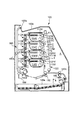
図13は本発明に係る画像形成装置の一実施例の概略断面構成を示す。本実施例では、本発明は、電子写真方式のカラーレーザビームプリンタにて具現化される。但し、本発明はこれに限定されるものではなく、電子写真方式を用いた画像形成装置に広く適用可能なものである。
Example 1
[Overall configuration of image forming apparatus]
FIG. 13 shows a schematic cross-sectional configuration of an embodiment of an image forming apparatus according to the present invention. In this embodiment, the present invention is embodied by an electrophotographic color laser beam printer. However, the present invention is not limited to this, and can be widely applied to an image forming apparatus using an electrophotographic system.
本実施例の画像形成装置100は、画像形成装置本体Aに通信可能に接続されたパーソナルコンピュータなどの外部機器から送られてきた信号に従って、電子写真方式により、転写材P、例えば、記録用紙、OHPシート或いは布などにカラー画像を形成することができる。
The
画像形成装置本体A内には、複数の像形成手段としてそれぞれイエロー、マゼンタ、シアン、ブラックの各色のトナー像を形成する複数の画像形成ユニット110Y、110M、110C、110Kが、ここでは略鉛直方向に直線状に配置されており、各画像形成ユニット110Y、110M、110C、110Kに対向するように、中間転写ユニット120が配置されている。詳しくは後述するように、中間転写ユニット120は、中間転写体(画像担持体)としてのベルト体(中間転写ベルト)1を、各画像形成ユニット110Y、110M、110C、110Kと対向して周回移動可能に有している。そして、本実施例では、このベルト体1の移動に伴って、その上に各画像形成ユニット110Y、110M、110C、110Kにて形成したトナー像を順次転写し、その後転写材Pに一括して転写することによって、転写材Pに所望の色数のトナー像が転写されたカラー画像を形成することができる。
In the image forming apparatus main body A, a plurality of
各画像形成ユニット110Y、110M、110C、110Kは、それぞれ形成するトナー像の色が異なることを除けば、同一の構成、作用を成すので、以下、特に区別を要しない場合は、各画像形成ユニット110Y、110M、110C、110Kのいずれかに属する要素であることを示すために図中符号に与えたY、M、C、Kの添え字は省略して総括的に説明する。
Each of the
画像形成ユニット110では、周知の電子写真画像形成プロセスによってトナー像を形成する。つまり、画像形成ユニット110には、像担持体として円筒型の電子写真感光体、即ち、感光ドラム111が図中矢印方向に回転可能に設けられている。画像形成動作においては、先ず、回転する感光ドラム111の表面を、帯電手段たる帯電ローラ112によって一様に帯電させる。次いで、コンピュータから送られてきた信号に従って、露光手段としてのレーザスキャナ113のレーザが発光し、帯電した感光ドラム111上を走査露光することによって、感光ドラム111上に静電像が形成される。感光ドラム111上に形成された静電像には、現像手段たる現像装置114が現像剤としてトナーを供給し、トナー像として可視化する。こうして感光ドラム111上に形成されたトナー像は、1次転写部T1において、ベルト体1を介して感光ドラム111と対向配置された1次転写手段たる1次転写ローラ121の作用によってベルト体1上に静電的に転写される。
The
上記のようなプロセスによって、ベルト体1の移動とタイミングをとって各画像形成ユニット110Y、110M、110C、110Kの感光ドラム111上に形成されたトナー像は、順次、ベルト体1上に重ね合わせて転写される。
The toner images formed on the photosensitive drums 111 of the respective
一方、転写材供給ユニット140において転写材収容部140aからピックアップローラ140bなどによって送り出された転写材Pが、レジストローラ140cにおいてタイミングをとって、2次転写手段たる2次転写ローラ130とベルト体1との当接部(2次転写部)T2へと搬送されてくる。こうして、ベルト体1上のトナー像は、2次転写部T2において、2次転写ローラ130の作用によって転写材Pに静電的に転写される。
On the other hand, the transfer material P fed from the
次いで、転写材Pはベルト体1から分離されて定着ユニット150へと搬送され、ここで、転写材P上のトナー像は加圧、加熱され、転写材P上に強固に定着される。その後、転写材Pは、排出ユニット160の搬送ローラ160a、160bなどによって搬送され、排出トレイ160c上に排出される。
Next, the transfer material P is separated from the
本実施例の画像形成装置100では、各画像形成ユニット110の感光ドラム111、帯電ローラ112、現像装置114は枠体によって一体的にカートリッジ化されて画像形成装置本体Aに対して着脱可能なプロセスカートリッジとされている。又、中間転写ユニット120も画像形成装置本体Aに対して着脱自在とされている。
In the
[ベルト張架装置]
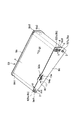
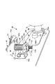
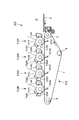
次に、本実施例にて最も特徴的なベルト張架装置について説明する。図1は本実施例におけるベルト張架装置50の外観を示す。
[Belt stretcher]
Next, the most characteristic belt stretcher in this embodiment will be described. FIG. 1 shows an appearance of a
先ず、ベルト張架装置50の全体構成について説明すると、ベルト張架装置50は、ベルト体1と、これを張架するための複数の張架部材として、ベルト体1を駆動するための駆動ローラ2、従動回転するプラテンローラ(従動ローラ)3及びテンションローラ4の3つのローラに張架されている。
First, the overall configuration of the
駆動ローラ2、プラテンローラ3、テンションローラ4は、それぞれ長手両端部を軸受け6(6a、6b)、7(7a、7b)、8(8a、8b)によって回転可能に支持されている。そして、第1、第2の側板9a、9bが、3つのローラを支持する軸受け6、7、8を保持する。
The driving
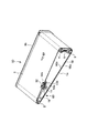
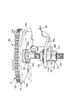
図2は、ベルト張架装置50の一方の側板(第1の側板)9aを外して内部が見えるようにした状態を示す。又、図3は、ベルト張架装置50のカットモデルであり、第1の側板9aの内側から、第1の側板9aに保持される部品を見た様子を示す(ベルト体1のうち、ベルト面は省略してある。)。
FIG. 2 shows a state where one side plate (first side plate) 9a of the
ベルト張架装置50を画像形成装置本体A内に収めた状態で、図13の紙面手前側に、ベルト張架装置50の第1の側板9aがあり、プラテンローラ3が、画像形成装置本体A内でベルト体1を介して2次転写ローラ130と当接して2次転写部T2を形成する。
In a state where the
駆動ローラ2は、画像形成装置本体Aに設けられた動力源(図示せず)から駆動が伝達されて回転する。これにより、ベルト体1は、図中矢印Bfにて示す方向に周回移動する。本実施例では、駆動ローラ2の可動側、即ち、第1の側板9a側の軸受け6aは、第1の側板9aに設けられた細長形状の軸受け保持穴9a1に、図中矢印FF/RR方向に滑動可能に保持され、一方、駆動ローラ2の第2の側板9b側の軸受け6bは、第2の側板9bに設けられた軸受け保持穴9b1に固定されている。これにより、駆動ローラ2は、第2の側板9b側の軸受け6bを揺動中心として、図3中矢印S1に示す方向に揺動可能とされている。
The driving
プラテンローラ3を軸支する軸受け7a、7bは、それぞれ第1、第2の側板9a、9bに設けられた軸受け保持穴9a2、9b2に固定されている。プラテンローラ3は、駆動ローラ2によってベルト体1を移動させることで従動回転する。
The
又、テンションローラ4は、図中矢印T方向、即ち、駆動ローラ2とプラテンローラ3との間に張架されたベルト体1で形成される平面から離間する方向に移動可能に保持されている。つまり、テンションローラ4を軸支する軸受け8a、8bは、第1、第2の側板9a、9bにそれぞれ設けられた細長形状の軸受け保持穴9a3、9b3に滑動可能に保持されており、この軸受け8a、8bは、付勢手段として、弾性部材であるテンションローラ付勢バネ5によって付勢される。これによって、ベルト体1に張力を与えている。テンションローラ4は駆動ローラ2によってベルト体2を移動させることで従動回転する。又、テンションローラ4は、プラテンローラ3と略平行に維持される。
Further, the tension roller 4 is held so as to be movable in the direction of arrow T in the drawing, that is, in a direction away from the plane formed by the
ベルト体1は、本実施例では、ポリイミドにて形成された周長675mm、幅258mm、厚さ60μmの無終端ベルトである。中間転写体の材料としては、これに限定されるものではないが、上記の他、ポリカーボネート、PVDF、ETFE、PTFE等により形成したベルト体1を好適に用い得る。ベルト体1は、その内側において、搬送方向(周回移動方向)Bfに対し略直交方向(幅方向)の一方の縁部(第1の側板9a側)1a近傍に、リブ16が取り付けられている。本実施例では、リブ16は、ベルト面に略垂直方向に起立し、ベルト体1の全周に亘り延在する、ウレタンにて形成された幅4mm高さ1.5mmの突起であり、ベルト体1の第1の側板9a側の縁部1aから0.5mm内側に設けられている。
In this embodiment, the
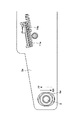
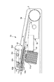
次に、図4、図5及び図7を参照して、ベルト張架装置50が備える寄り戻し手段としての調心機構(調心ユニット)60について説明する。前述のように、ベルト機構においては、駆動時にベルト体1の寄り(片寄り)が発生することがあり、ベルト体の破損などを防ぎ、又良好な画質を維持するために、この寄れを有効に補正する必要がある。そのため、本実施例におけるベルト張架装置50は、以下説明するような、ベルト体1の調心ユニット60を備えている。図4、5は調心ユニット60を拡大して示す(ベルト体1のうち、ベルト面は省略してある。)。
Next, with reference to FIG. 4, FIG. 5 and FIG. 7, an alignment mechanism (alignment unit) 60 as a back- feeding means included in the
本実施例では、上述のように、ベルト張架装置50は、感光ドラム111上のトナー像を転写材Pへ転写するためのベルト体1と、ベルト体1を張架する第1の張架部材(プラテンローラ3又はテンションローラ4)と、ベルト体1を張架するとともに第1の張架部材に対する角度を変更することが可能な第2の張架部材(駆動ローラ2)と、を有する。そして、ベルト張架装置50は、ベルト体1と接触することができ、ベルト体1との接触状態が変化するように構成された接触部材13a、13bを有し、この接触部材13a、13bとベルト体1との接触状態に応じて第2の張架部材(駆動ローラ2)の第1の張架部材(プラテンローラ3又はテンションローラ4)に対する角度が変化するようにされている。これにより、ベルト体1は、図中矢印N/M方向、即ち、ベルト体1の搬送方向Bfに対し略直交方向に移動する。
In the present embodiment, as described above, the
本実施例では、接触部材13a、13bは、ベルト体1と接触することによってベルト体1の駆動力を受けることができるように構成し、このベルト体1から入力される駆動力によって、駆動ローラ2のプラテンローラ3又はテンションローラ4に対する角度が変化するようにする。
In the present embodiment, the
又、ベルト体1の搬送方向Bfに対して略直交方向におけるベルト体1の位置によって、接触部材13a、13bにベルト体1の駆動力が入力される量が異なり、又、ベルト体1の搬送方向に対し略直交方向におけるベルト体1の位置によって、第1、第2の接触部材13a、13bに駆動力が入力される場合と駆動力が入力されない場合があるようにし、第1の接触部材13aと、第2の接触部材13bに入力される駆動力によって、駆動ローラ2のプラテンローラ3又はテンションローラ4に対する角度が逆方向に変化するようにする。
Further, the amount of the driving force of the
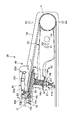
本実施例では、調心ユニット60は、ベルト体1の搬送方向Bfに対し略直交方向の端部近傍、ここではベルト体1に設けられた駆動入力部たるリブ16の対向する側面16a、16bにそれぞれ接触可能に設けられた接触手段としての、第1、第2の接触部材たる回転自在な第1、第2のコロ(回転部材)13a、13bと;第1、第2のコロ13a、13bの回転力が伝達される回転自在な回転体としての、ネジ付きギア11のギア部11aと;ギア部11aと同軸で一体となって回転する駆動手段としての、ネジ付きギア11のネジ部(螺旋形状ボス)11bと;ネジ部11bに係合しネジ部11bの回転により駆動される移動子たるナット17と;ナット17の動きを、プラテンローラ3又はテンションローラ4に対する平行度が変更可能に保持されている駆動ローラ2の可動部に伝える連結子たるレバー18と;を有する。ネジ付きギア11、ナット17及びレバー18は、第1、第2のコロ13a、13bの作動によって駆動ローラ2にベルト体1の回転方向の移動力を伝達し、駆動ローラ2のプラテンローラ3又はテンションローラ4に対する角度を変える動力変換手段を構成する。
In the present embodiment, the aligning
斯かる構成により、ベルト体1が搬送方向Bfに対し略直交方向(図中矢印M又はN方向)に移動した際に、ベルト体1に設けられたリブ16が第1又は第2のコロ13a又は13bに接触して、第1又は第2のコロ13a又は13bが回転する。そして、第1又は第2のコロ13a又は13bの回転力が同一の回転体たるネジ付きギア11のギア部11aに伝達され、ギア部11a及びネジ部11bが回転することでナット17がネジ部11bの長手方向に沿って図中矢印U又はD方向に移動する。このナット17の動きが、レバー18に伝達され、駆動ローラ2の可動部、即ち、第1の側板9a側の軸受け6aを図中矢印FF又はRR方向に移動させる。
With such a configuration, when the
ここで、レバー18が駆動ローラ2の可動部を移動させて、駆動ローラ2とプラテンローラ3又はテンションローラ4に対する平行度を変えた時に、駆動ローラ2の傾きの変化方向が、ベルト体1が搬送方向Bfに対し略直交方向において移動した方向とは逆になるようにする。このことで、ベルト体がM又はN方向へ移動していた方向とは逆の方向へ戻されることとなるものである。
Here, when the
以下、図6〜図11をも参照して、本実施例におけるベルト体1の調心機構60についてより詳細に説明する。尚、以下の説明において、調心ユニット60に関する方向について言及する場合、駆動ローラ2とテンションローラ4との間に張架されるベルト体1の表面側を「上」、裏面(リブ16が設けられた面)側を「下」、更に第1の側板9a側を「左」、第2の側板9b側を「右」とする。
Hereinafter, the
調心ユニット60は、第1の側板9aに固定された調心ユニットシャーシ10を有する。調心ユニットシャーシ10は、駆動ローラ2とテンションローラ4との間に張架されたベルト体1の表面と略平行なシャーシ本体10aと、シャーシ本体10aに対し略直交方向に延在するシャーシ取り付け部10bとを備え、シャーシ取り付け部10bを第1の側板9aに沿わせて固定することで、調心ユニットシャーシ10を所定位置に配置する。この調心ユニットシャーシ10にコロ13a、13b、ネジ付きギア11等が取り付けられる。
The aligning
本実施例では、ネジ付きギア11は、ネジ部11bの長手方向(上下方向)には移動せず、且つ、回転自在となるように、調心ユニットシャーシ10のシャーシ本体10aに取り付けられる。ネジ付きギア11の取り付け部近傍の断面をより詳しく示す図11を参照すると分かるように、ネジ付きギア11は、ギア部11aとネジ部11bとの連結部近傍において回転軸を成す摺動部11cが、調心ユニット10のシャーシ本体10aに設けられた軸受け部10cにより回転可能に支持される。又、この軸受け部10cの下側近傍に位置してネジ付きギアのネジ部11bに設けられた溝部11dに緊定部材12を固定することで、ネジ部11bを挿通して軸受け部10cの下部に配置されたワッシャ15aにこの緊定部材12が突き当たり、ネジ付きギア11がネジ部11bの長手方向に移動しないようになっている。
In this embodiment, the threaded
第1、第2のコロ13a、13bは、本実施例では、その外周に弾性摩擦体が設けられた摩擦体リングである。ここでは、弾性摩擦体としてEPDMを使用したが、この他、クロロプレンゴム、ウレタンゴム、ウレタンフォーム等を好適に使用し得る。又、本実施例では、第1、第2のコロ13a、13bのそれぞれの下側には、第1、第2の小ギア14a、14bが固定されている。第1、第2のコロ13a、13bは、ベルト体1のリブ16に対して所定のクリアランスを持ち、且つ、第1、第2の小ギア14a、14bがネジ付きギア11のギア部11aと係合するように、調心ユニットシャーシ10のシャーシ本体10a上に回転自在に取り付けられる。
In the present embodiment, the first and
ナット17は、ネジ付きギア11のネジ部11bに螺合され、ネジ部11bの回転方向に回転しないように保持される。本実施例では、レバー18の駆動受け部18aに設けられた矩形形状の摺動穴18bを、ナット17の対向する略一様に平坦な側面17aに沿わせて通す。これによって、ナット17の上端側のつば部17bと、下端側の溝部17cに取り付けられる緊定部材36との間で、図中矢印Q1、Q2方向にガタをもって、駆動受け部18aでナット17を回転不可能に保持する。
The
ネジ付きギア11のネジ部11bを挿通して緊定部材12の下部に配置されたワッシャ15bと、ナット17の上端つば部17bとの間において、ネジ付きギア11のネジ部11bの周囲には付勢手段として、弾性体である付勢バネ35が設けられている。付勢バネ35は、ナット17が、図中矢印U/D方向に移動し、ネジ付きギア11のネジ部11bから外れた状態になった場合に、ネジ部11bが逆回転した時に再度ネジ部11bに螺合するようにナット17を中心位置方向へ付勢する。
Between the
レバー18は、上述のようにその長手一端部に設けられた駆動受け部18aでナット17を保持すると共に、ナット17の図中矢印U/D方向の動きを受けて、これを駆動ローラ2の可動部、即ち、第1の側板9a側の軸受け6aに伝達する。本実施例では、レバー18は、軸穴18dが第1の側板9aに設けられた回動中心軸19に嵌入され、該回動中心軸19を中心として回動自在に第1の側板9aに保持されている。そして、レバー18の駆動受け部18aとは反対側の端部18cは、駆動ローラ2の第1の側板9a側の軸受け6aに固定されている。
As described above, the
又、本実施例では、調心ユニット60には、リブ16を、第1、第2のコロ13a、13bに駆動力を入力可能な領域に保持するようにガイドするリブ案内手段30が設けられている。リブ案内手段30は、リブ16が第1、第2のコロ13a、13b間から上下に外れないように、リブ16をそれぞれ下側、上側から挟み込む、ガイド31及びガイドレバー32を有する。ガイドレバー32は、揺動中心軸32cを中心として図中矢印S3方向に揺動可能に第1の側板9aに支持されている。ガイドレバー32は、その長手方向一端部において、付勢手段として弾性部材であるバネ32dによって付勢されている。そして、ガイドレバー32は、長手方向もう一方の端部近傍に設けられた挟持部32aで、ガイド31との間でリブ16(及びベルト体11)を挟持する。又、ガイドレバー32は、挟持部32a側の端部にストッパ32bを有し、ガイドレバー32によってベルト体11を押し過ぎないようガイド31とのクリアランスを保持するように、このストッパ32bの先端が調心ユニットシャーシ10のシャーシ本体10aに突き当てられる。
In the present embodiment, the aligning
次に、調心ユニット60の作用について更に説明する。
Next, the operation of the
ベルト体1は、駆動ローラ2によって駆動されて図中矢印Bf方向に回転する。この際、駆動ローラ2、プラテンローラ3、テンションローラ4及びベルト体1の精度や平行度をいかに高精度に管理したとしても、ベルト体1は図中矢印N/Mのいずれかの方向に寄る傾向を持つ。
The
従来は、規制部材として設けられたフランジ(図示せず)によってリブ16の動きが規制され、ベルト体1の搬送方向Bfに対し略直交方向への動きが停止するようにされていた。しかし、この状態においては、リブ16とフランジとの間には大きな摩擦力が働いているため、リブ16が削れ、フランジとの摩擦力が大きくなり、フランジを乗り上げ、ベルト体1の位置を所定位置にとどめることができなくなり、リブ16とベルト体1の破損に至ることがあった。
Conventionally, the movement of the
これに対して、本実施例のベルト張架装置50では、上記構成の調心ユニット60がベルト体1の自動調心作用を成すため、上記問題は発生しない。
On the other hand, in the
ここで、本実施例のベルト張架装置50において、仮にベルト体1が図中矢印N方向に寄った場合について説明する。この場合、リブ16の第1の側面(左側側面)16aが第1のコロ13aに接触する。そして、第1のコロ13aとこれに一体的に連結された第1の小ギア14aは、図中矢印R1方向に回転する。その結果、第1の小ギア14aと係合しているネジ付きギア11のギア部11aが同矢印R2方向に回転し、同時にネジ付きギア11のネジ部11bが同方向に回転する。これにより、ネジ部11bに螺合された回転不可能なナット17を、図中矢印D方向(下方)に移動させる。そのため、レバー18は、ナット17の移動により、つば部17bに押されて駆動受け部18aがD方向に移動され、図中矢印X1方向に回動する。これにより、レバー18は、駆動ローラ2の第1の側板9a側の軸受け6aを、図中矢印X2方向(上方)に移動させる。
Here, in the
こうして、駆動ローラ2の第1の側板9a側の軸受け6aをX2方向に移動させると、駆動ローラ2のプラテンローラ3又はテンションローラ4に対する角度が変化する。このように、駆動ローラ2のアライメントが傾くと、ベルト体1は、図中矢印N方向の寄り傾向が減退し、図中矢印M方向に寄り始めるため、リブ16は第1のコロ13aから離れる。
Thus, when the
この作用によって、当初ベルト体1が図中矢印N方向に寄った場合は、リブ16と第1のコロ13aとの接触が無くなるまで寄り傾向を打ち消す方向に駆動ローラ2のアライメントが調整される。
With this action, when the
同様に、ベルト体1が図中矢印M方向(上記とは逆方向)に寄り、第2のコロ13bにリブ16の第2の側面16bが接触した場合は、第2のコロ13bとこれに一体的に連結された第2の小ギア14bが図中矢印R3方向に回転するため、ネジ付きギア11のギア部11aとネジ部11bは図中矢印R4方向に回転する。これにより、ナット17が図中矢印U方向(上方)に移動され、レバー18が図中矢印X3方向に回動し、駆動ローラ2の第1の側板9a側の軸受け6aを、図中矢印X4方向(下方)に移動させる。これにより、駆動ローラ2のアライメントは、上記とは逆方向に傾く。
Similarly, when the
上述のような作用により、リブ16は、第1、第2のコロ13a、13bの間に常に位置するように制御され、ベルト体1もリブ16がその範囲に存在する位置に保持される。
The
ここで、好ましくは、ベルト体1自体に外力(摩擦力)が加わるなどして、駆動ローラ2に外力が働いた時に、その外力によってネジ付きギア11が回されないように調心ユニット60を構成する。ここでは、下記のパラメータ群を以下説明するように設定する。
Here, preferably, when an external force is applied to the driving
(a)ネジ付きギア11のネジ部11bとナット17の互いの摩擦係数をμsn
(b)ネジ付きギア11とネジ付きギア11のネジ部11bの長手方向の移動を規制する軸受けとの摩擦係数をμsb
(c)ネジ部11bの外径をφs
(d)ネジ付きギア11の軸受けと摺動する部分のネジ部11bの中心からの距離をrs
(e)ネジ部11bのピッチをPs
(f)ナット17にかかる外力による推力をF
(A) The mutual friction coefficient between the threaded
(B) The coefficient of friction between the threaded
(C) The outer diameter of the
(D) The distance from the center of the threaded
(E) The pitch of the
(F) The thrust generated by the external force applied to the
このとき、ネジ部11bを回そうとするモーメントは、下記式(1)、
F・Ps/(φs・π)・φs/2 ・・・(1)
で表される。
At this time, the moment to turn the
F · Ps / (φs · π) · φs / 2 (1)
It is represented by
一方、推力Fによる摩擦モーメントは、下記式(2)、
F・cosθ2・μsn・φs/2+F・μsb・rs ・・・(2)
で表される。
On the other hand, the frictional moment due to the thrust F is expressed by the following equation (2),
F · cos θ 2 · μsn · φs / 2 + F · μsb · rs (2)
It is represented by
よって、下記式(3)、
式(2)>式(1) ・・・(3)
となるようにすることで、駆動ローラ2に外力が働いた時に、その外力によってネジ付きギア11が回されないようにすることができる。
Therefore, the following formula (3),
Formula (2)> Formula (1) (3)
By doing so, when an external force is applied to the
ここで、
cosθ2=(φs・π)2/((φs・π)2+Ps2)
である。
here,
cos θ 2 = (φs · π) 2 / ((φs · π) 2 + Ps 2 )
It is.
より具体的には、上記式(3)を満たすように、ネジ付きギア11のネジ部材質、ナット17の材質、ネジ付きギア11とネジ付きギア11のネジ部11bの長手方向の移動を規制する軸受けの材質、ネジ部11bの外径φs、ネジ付きギア11の軸受けと摺動する部分のネジ部11bの中心からの距離rs、ネジ部11bのピッチPs、等を適宜設定すればよい。一具体例として、ここでは、ネジ付きギア11のネジ部の材質として、ニッケルメッキを施した鉄、ナット17の材質としてPOM、ネジ付きギア11とネジ付きギア11のネジ部11bの長手方向の移動を規制する軸受けの材質としてPOM、ネジ部11bの外径φs=3mm、ネジ付きギア11の軸受けと摺動する部分のネジ部11bの中心からの距離rs=2.5mm、ネジ部11bのピッチPs=0.5mm等を選定することで、
μsn:0.3
μsb:0.3
φs: 3mm
rs: 2.5mm
Ps: 0.5mm
に設定した。これにより、上記式(3)を満足する(Fは式3において両辺にかかっている係数であるため、式3はFの値に関係なく成立する。)。
More specifically, the longitudinal movement of the threaded
μsn: 0.3
μsb: 0.3
φs: 3mm
rs: 2.5 mm
Ps: 0.5mm
Set to. As a result, the above formula (3) is satisfied (F is a coefficient applied to both sides in
尚、本実施例では、ベルト張架装置50は、3本のローラを使用したものであるとして説明したが、本発明においては少なくとも2本のローラがあればよく、ローラの本数に関係なくベルト体1の調心作用は作動する。
In the present embodiment, the
又、ネジ付きギア11のネジ部11bのピッチは一定である必要はなく、ベルト体1の寄り速度の応答に合わせて、ネジ部11bのピッチを、例えば、ネジ部11bの長手方向中央部では粗く、両端部側、即ち、ギア部11aとの連結部側端部近傍及び先端近傍では細かくすることで、応答の伝達関数を調整し、調心が収束するまでにかかる時間を短縮することができる。この場合、ナット17側のネジは、1巻き以下にする。
Further, the pitch of the threaded
以上、本実施例の構成によれば、張架部材たるローラの精度・平行度、ベルト体1及び/又はリブ16の精度を厳しく管理する必要なく、設置時の装置のゆがみ、及び、耐久使用による寄り傾向をリアルタイムに自動的に補正することにより、ベルト体1及び/又はリブ16に継続的なストレスをかけず、所定の位置に保持することができ、ベルト体1及び/又はリブ16が規制部材に乗り上げることによる破損も回避することができる。
As described above, according to the configuration of the present embodiment, it is not necessary to strictly control the accuracy and parallelism of the rollers as the stretch members and the accuracy of the
以上、本実施例によれば、
(1)ベルト体1が伸縮性が無く、破れやすい材質であっても長時間所定の位置に保持した状態で回転させることができるため、ベルト体1の材質の選択範囲が広がり、用途に最適な材質を選択することができるようになる。特に、ベルト体1を中間転写体などとして用いる場合には、静電的特性、及び画像をゆがませずに保持する性質が必要であることから、伸縮性の小さな、薄いベルトが好適であるため極めて有効である。
(2)又、使用状態に応じてベルトが正しい位置に来るように自立的にベルト体1を調心する機構であるため、ベルト体1若しくはローラの寸法形状、又はローラの平行度に厳しい精度を必要としない。更には、ベルト張架装置50の設置精度に関しても厳しい精度は不要になる。これにより安価で耐久性の高く、ベルト体1の位置精度の良いベルト張架装置50を実現することができる。
(3)又、本実施例の構成によれば、ローラに外力が加わった場合でもローラの位置が変わることがないため、ベルト張架装置50を輸送する前後においてローラの位置が変わることはなく、輸送後でもベルト体1が大きな寄り傾向を示すことなく安定した走行を実現できる。
(4)又、ベルト体1を中間転写体などとして用いるような場合、ベルト体1自体に外力(摩擦力)が加わるが、その外力はローラに対する外力となる。本実施例の構成では、第1の張架部材(プラテンローラ3又はテンションローラ4)に対する角度を変更可能な第2の張架部材(駆動ローラ2)に加わる外力が回転体たるネジ付きギア11のギア部11aに伝わり、これが第1、第2の小ギア14a、14bを備える第1、第2のコロ13a、13bに伝わる構成においても、ベルト体1の走行を阻害したり、リブ及び/又はベルト体1が第1、第2のコロ13a、13b等と強く摺擦することによって変音を発生したり、異常摩耗に至るような問題は発生しない。
(5)又、一般に、中間転写ユニット120を交換可能にするためには、ベルト張架装置50を画像形成装置本体Aから外す必要がある。本発明により、ベルト張架装置50が、取り付け状態によらず自立的にベルト体1の調心を行うことから、ユニット着脱時の取り付け状態変化がベルト体1の寿命に影響を及ぼすことなく安定して使用できる。
といった効果を奏し得る。
As described above, according to this embodiment,
(1) Even if the
(2) In addition, since the
(3) Also, according to the configuration of this embodiment, the position of the roller does not change even when an external force is applied to the roller, so the position of the roller does not change before and after the
(4) When the
(5) In general, in order to make the
Such effects can be achieved.
実施例2
次に、本発明の他の実施例について説明する。本実施例において、本発明が適用される画像形成装置、画像形成装置が備えるベルト張架装置の基本構成は、実施例1のものと同じであるので、実施例1のものと同一若しくは相当する機能、構成を有する要素には同一符号を付し、詳しい説明は省略する。
Example 2
Next, another embodiment of the present invention will be described. In this embodiment, the basic configuration of the image forming apparatus to which the present invention is applied and the belt stretching device provided in the image forming apparatus is the same as or equivalent to that of the first embodiment. Elements having functions and configurations are denoted by the same reference numerals, and detailed description thereof is omitted.
図12は、本実施例におけるベルト張架装置51の調心ユニット61の特徴を最もよく示す、ベルト張架装置50の第1の側板9aを内側から見た側面図である。
FIG. 12 is a side view showing the
実施例1においては、レバー18の駆動受け部18aとナット17とが、ガタ(図中矢印Q1、Q2方向)を持って係合していた。つまり、実施例1では、接触部材たる第1、第2のコロ13a、13bの回転力が伝達されて回転する駆動手段(ネジ付きギア11のネジ部11b)で駆動されて移動する移動子(ナット17)と、レバー18の駆動受け部18aとが別部材とされていた。
In the first embodiment, the
これに対して、本実施例では、これら駆動手段と移動手段とを一体化する。更に説明すると、本実施例では、回転体としてのネジ付きギア11のギア部11aと一体に回転するウォーム(螺旋形状ボス)11dと、連結子たるレバー18の先端に設けられた部分的なウォームホイール18fとによるウォームギアにより、レバー18を駆動する。このように、本実施例では、移動子たるウォームホイール18fと、レバー18の駆動受け部とが一体化されている。
On the other hand, in this embodiment, these driving means and moving means are integrated. More specifically, in this embodiment, a worm (spiral boss) 11d that rotates integrally with a
以上、本実施例の構成によれば、実施例1と同様の効果を奏し得ると共に、部品点数が少なくなり、ガタが少なくなるので、調心作用の応答性が向上する。 As described above, according to the configuration of the present embodiment, the same effects as those of the first embodiment can be obtained, and the number of parts is reduced and the backlash is reduced, so that the responsiveness of the aligning action is improved.
実施例3
次に、本発明の更に他の実施例について説明する。
Example 3
Next, still another embodiment of the present invention will be described.
上記各実施例では、ベルト体1は中間転写体(中間転写ベルト)であるとして説明したが、本発明はこれに限定されるものではない。
In each of the above embodiments, the
当業者には周知の通り、従来、一つ以上の像担持体上に形成したトナー像を、その像担持体と対向して周回移動可能な転写材担持体上に担持されて搬送される転写材に転写し、その後トナー像が転写された転写材を転写材担持体から分離して、トナー像を転写材上に定着させて記録画像を得る方式の画像形成装置がある。 As is well known to those skilled in the art, conventionally, a toner image formed on one or more image carriers is transferred and carried on a transfer material carrier that can be moved around in opposition to the image carrier. There is an image forming apparatus of a type that obtains a recorded image by separating a transfer material onto which a toner image has been transferred and then transferring the toner image from a transfer material carrier and fixing the toner image on the transfer material.
図14は、斯かる方式の画像形成装置の一例の概略断面構成を示す。図示の例では、画像形成装置101は、複数の像形成手段としてそれぞれイエロー、マゼンタ、シアン、ブラックの各色のトナー像を形成する各画像形成ユニット110Y、110M、110C、110Kを有する。各画像形成ユニットにおいて像担持体たる感光ドラム111Y、111M、111C、111K上にトナー像を形成するプロセスは、実施例1にて説明したものと同様であるため、実施例1の画像形成装置100と同一若しくは相当する機能、構成を有する要素には同一符号を付し詳しい説明は省略する。
FIG. 14 shows a schematic cross-sectional configuration of an example of such an image forming apparatus. In the illustrated example, the
各画像形成ユニット110Y、110M、110C、110Kにおける感光ドラム111Y、111M、111C、111K上へのトナー像の形成と同期するように、図示しない転写材供給ユニットから転写材Pが送り出され、転写材担持体たるベルト体1上に供給される。そして、各感光ドラム111Y、111M、111C、111K上に形成された各色のトナー像が、ベルト体1を介して各感光ドラム111Y、111M、111C、111Kに対向配置された転写手段115Y、115M、115C、115Kの作用によって、ベルト体1上を搬送される転写材P上に順次転写される。この転写工程が終了すると、転写材Pは、ベルト体1から分離されて図示しない定着手段たる定着装置に搬送され、ここで未定着トナー像の定着処理を受けた後、機外に排出される。
A transfer material P is sent out from a transfer material supply unit (not shown) so as to synchronize with the formation of toner images on the
本発明は、このような転写材担持体として用いられるベルト体1を備える画像形成装置にも好適に適用し得るものである。即ち、図14の画像形成装置101において、転写材搬送ユニット170(画像形成装置本体Aに対し着脱可能であっても固定であってもよい。)が、上記各実施例にて説明した調心ユニット60を備えたベルト張架装置50を有する構成とすることで、上記各実施例と同様の作用効果を奏し得る。
The present invention can also be suitably applied to an image forming apparatus including the
1 ベルト体(中間転写体、転写材担持体)
2 駆動ローラ(第2の張架部材)
3 プラテンローラ(第1の張架部材)
4 テンションローラ(第1の張架部材)
10 調心ユニットシャーシ
10c ネジ付きギアの軸受け部
11 ネジ付きギア
11a ギア部(回転体)
11b ネジ部(駆動部)
13a、13b 第1、第2のコロ(接触部材)
14a、14b 第1、第2の小ギア(駆動伝達部)
16 リブ(駆動入力部)
17 ナット(移動子)
18 レバー(連結子)
30 リブ案内手段
1 Belt body (intermediate transfer body, transfer material carrier)
2 Drive roller (second tension member)
3 Platen roller (first stretch member)
4 Tension roller (first stretch member)
DESCRIPTION OF
11b Screw part (drive part)
13a, 13b First and second rollers (contact members)
14a, 14b 1st, 2nd small gear (drive transmission part)
16 ribs (drive input section)
17 Nut (Mover)
18 Lever (connector)
30 Rib guide means
Claims (4)
前記寄り戻し手段は、前記ベルト体が前記回転方向と直交する方向に寄ると前記ベルト体が接触する位置に設けられ回転している前記ベルト体と接触することで前記ベルト体に従動して回転する接触部材と、前記第2の張架ローラと連結しており前記接触部材が回転することで前記第1の張架ローラに対して前記第2の張架ローラを移動させるレバーと、を有し、前記ベルト体が前記ベルト体の回転方向と直交する方向に寄った場合、前記寄り戻し手段は、前記レバーを移動させることで前記第1の張架ローラの回転軸と前記第2の張架ローラの回転軸の成す角度を変更して前記ベルト体を寄り方向と逆方向に移動させることを特徴とする画像形成装置。 An endless belt member rotatable, a first tension roller rotatable support and tension the belt body, a second tension roller rotatable support and tension the belt body, the belt body By changing the angle formed by the rotation axis of the first tension roller and the rotation axis of the second tension roller when the direction is perpendicular to the direction of rotation of the belt element, the belt body is shifted. An image forming apparatus for transferring a toner image from the belt body to a transfer material or transferring a toner image to a transfer material carried by the belt body.
The retraction means is rotated by following the belt body by contacting with the rotating belt body provided at a position where the belt body contacts when the belt body approaches a direction orthogonal to the rotation direction. A contact member that is connected to the second tension roller, and a lever that moves the second tension roller relative to the first tension roller when the contact member rotates. When the belt body moves in a direction perpendicular to the rotation direction of the belt body, the retraction means moves the lever to move the rotation shaft of the first stretching roller and the second tensioning member. An image forming apparatus, wherein the belt body is moved in a direction opposite to the direction of shifting by changing an angle formed by a rotation axis of the gantry roller .
Priority Applications (6)
| Application Number | Priority Date | Filing Date | Title |
|---|---|---|---|
| JP2003329180A JP4366162B2 (en) | 2003-09-19 | 2003-09-19 | Image forming apparatus |
| EP04022068A EP1517190B1 (en) | 2003-09-19 | 2004-09-16 | Image forming apparatus with meandering correction of a belt member |
| CNB2004100782202A CN100504632C (en) | 2003-09-19 | 2004-09-17 | Image forming apparatus |
| US10/943,030 US7239828B2 (en) | 2003-09-19 | 2004-09-17 | Image forming apparatus with adjustment of belt member |
| US11/756,982 US7389068B2 (en) | 2003-09-19 | 2007-06-01 | Image forming apparatus with adjustment of belt member |
| US11/756,994 US7379690B2 (en) | 2003-09-19 | 2007-06-01 | Image forming apparatus with adjustment of belt member |
Applications Claiming Priority (1)
| Application Number | Priority Date | Filing Date | Title |
|---|---|---|---|
| JP2003329180A JP4366162B2 (en) | 2003-09-19 | 2003-09-19 | Image forming apparatus |
Publications (2)
| Publication Number | Publication Date |
|---|---|
| JP2005092153A JP2005092153A (en) | 2005-04-07 |
| JP4366162B2 true JP4366162B2 (en) | 2009-11-18 |
Family
ID=34191414
Family Applications (1)
| Application Number | Title | Priority Date | Filing Date |
|---|---|---|---|
| JP2003329180A Expired - Fee Related JP4366162B2 (en) | 2003-09-19 | 2003-09-19 | Image forming apparatus |
Country Status (4)
| Country | Link |
|---|---|
| US (3) | US7239828B2 (en) |
| EP (1) | EP1517190B1 (en) |
| JP (1) | JP4366162B2 (en) |
| CN (1) | CN100504632C (en) |
Families Citing this family (19)
| Publication number | Priority date | Publication date | Assignee | Title |
|---|---|---|---|---|
| JP4366162B2 (en) * | 2003-09-19 | 2009-11-18 | キヤノン株式会社 | Image forming apparatus |
| KR100618326B1 (en) * | 2004-08-31 | 2006-08-31 | 삼성전자주식회사 | Belt clutch apparatus and image forming apparatus thereof |
| US7430393B2 (en) * | 2006-07-03 | 2008-09-30 | Canon Kabushiki Kaisha | Belt feeding device and image heating device |
| US8095053B2 (en) | 2007-04-17 | 2012-01-10 | Kabushiki Kaisha Toshiba | Transfer belt unit for image forming apparatus including a steering roller to correct meandering |
| JP4324621B2 (en) * | 2007-04-17 | 2009-09-02 | シャープ株式会社 | Intermediate transfer unit attaching / detaching mechanism and intermediate transfer unit attaching / detaching method |
| JP5078503B2 (en) * | 2007-08-22 | 2012-11-21 | キヤノン株式会社 | Belt conveying apparatus and image forming apparatus |
| JP5063273B2 (en) * | 2007-09-21 | 2012-10-31 | キヤノン株式会社 | Belt conveying apparatus and image forming apparatus |
| US7873311B2 (en) * | 2007-12-05 | 2011-01-18 | Kabushiki Kaisha Toshiba | Belt transfer device for image forming apparatus |
| CN101279550B (en) * | 2008-04-16 | 2010-11-10 | 株式会社东芝 | Transfer printing belt device and self-turning method of transfer printing belt |
| CN101934649A (en) * | 2008-04-16 | 2011-01-05 | 株式会社东芝 | Belt device and belt self-steering method |
| US20110070001A1 (en) * | 2009-09-22 | 2011-03-24 | Kabushiki Kaisha Toshiba | Steering Mechanism for Belt Unit |
| JP2013076863A (en) | 2011-09-30 | 2013-04-25 | Canon Inc | Belt conveyance device and image forming apparatus |
| JP5870784B2 (en) * | 2012-03-16 | 2016-03-01 | カシオ電子工業株式会社 | Belt misalignment correction mechanism and image forming apparatus including the same |
| JP6112781B2 (en) | 2012-06-01 | 2017-04-12 | キヤノン株式会社 | Image forming apparatus |
| TW201350352A (en) * | 2012-06-04 | 2013-12-16 | Hon Hai Prec Ind Co Ltd | Belt adjusting device for printer |
| JP6164522B2 (en) * | 2012-12-27 | 2017-07-19 | 株式会社リコー | Belt device and image forming apparatus |
| JP6422290B2 (en) * | 2014-10-02 | 2018-11-14 | キヤノン株式会社 | Image forming apparatus |
| CN111589214B (en) * | 2020-05-14 | 2022-04-29 | 郑州沃特节能科技股份有限公司 | Filter screen belt device for steel slag treatment |
| CN113040571B (en) * | 2021-04-15 | 2022-05-03 | 吾将文化科技集团有限公司 | Interactive stand based on hydraulic pressure |
Family Cites Families (37)
| Publication number | Priority date | Publication date | Assignee | Title |
|---|---|---|---|---|
| JPS5760347A (en) * | 1980-09-29 | 1982-04-12 | Toshiba Corp | Snake motion preventing apparatus for belt |
| US4429985A (en) | 1981-02-20 | 1984-02-07 | Ricoh Company, Ltd. | Recording system provided with a device for correcting deviation of recording member in endless belt form |
| JPS57200050A (en) | 1981-06-04 | 1982-12-08 | Ricoh Co Ltd | Self-correcting device for endless belt meandering |
| US4397538A (en) * | 1981-09-03 | 1983-08-09 | Xerox Corporation | Belt alignment system |
| US4483607A (en) * | 1982-09-06 | 1984-11-20 | Ricoh Company, Ltd. | Recording system |
| JPS6057043A (en) | 1983-09-09 | 1985-04-02 | Ricoh Co Ltd | Receiving mechanism of belt tension roller |
| US5017969A (en) * | 1988-05-30 | 1991-05-21 | Canon Kabushiki Kaisha | Device having movable belt |
| JPH0699055B2 (en) | 1990-05-24 | 1994-12-07 | バンドー化学株式会社 | Belt drive |
| EP0458260B1 (en) | 1990-05-24 | 1996-08-21 | Bando Chemical Industries, Limited | Belt driving system |
| JPH0460916A (en) | 1990-06-26 | 1992-02-26 | Kubota Corp | Metal thin film type magnetic recording medium |
| JPH0514046A (en) | 1991-07-05 | 1993-01-22 | Mitsubishi Electric Corp | Phased array antenna |
| JP2788683B2 (en) | 1991-09-17 | 1998-08-20 | シャープ株式会社 | Belt meander control device |
| JPH05324074A (en) * | 1992-05-21 | 1993-12-07 | Nec Niigata Ltd | Device for correcting belt position of electrophotographic printer |
| JP3209451B2 (en) | 1992-06-23 | 2001-09-17 | キヤノン株式会社 | Image forming device |
| US5246099A (en) * | 1992-09-23 | 1993-09-21 | Xerox Corporation | Belt steering roller mechanism and steering roll construction |
| JPH06255826A (en) | 1993-03-09 | 1994-09-13 | Toshiba Corp | Image forming device |
| US5410389A (en) * | 1993-08-30 | 1995-04-25 | Xerox Corporation | Neutral side force belt support system |
| US5717984A (en) * | 1996-01-11 | 1998-02-10 | Xerox Corporation | Driving, steering and tensioning roll for belt loops |
| JPH10231041A (en) | 1997-02-19 | 1998-09-02 | Fuji Xerox Co Ltd | Belt meandering controller and image forming device |
| JPH11106081A (en) | 1997-10-01 | 1999-04-20 | Ricoh Co Ltd | Photosensitive belt skew stopping mechanism for electrophotographic device |
| KR100584533B1 (en) * | 1998-07-21 | 2006-05-30 | 삼성전자주식회사 | Apparatus for adjusting belt for printer |
| JP2000075697A (en) | 1998-08-28 | 2000-03-14 | Bando Chem Ind Ltd | Belt type fixing device |
| JP2000075708A (en) | 1998-08-28 | 2000-03-14 | Bando Chem Ind Ltd | Belt fixing device |
| JP2000072218A (en) | 1998-08-28 | 2000-03-07 | Bando Chem Ind Ltd | Belt drive |
| JP2000075699A (en) | 1998-08-28 | 2000-03-14 | Bando Chem Ind Ltd | Belt type fixing device |
| JP2000075700A (en) | 1998-08-28 | 2000-03-14 | Bando Chem Ind Ltd | Belt type fixing device |
| JP2000075698A (en) | 1998-08-28 | 2000-03-14 | Bando Chem Ind Ltd | Belt type fixing device |
| JP4207269B2 (en) * | 1998-10-23 | 2009-01-14 | リコープリンティングシステムズ株式会社 | Belt drive |
| JP2000199550A (en) | 1999-01-05 | 2000-07-18 | Ricoh Co Ltd | Belt drive device and belt fixing device as well as image forming device |
| US6134406A (en) * | 1999-03-11 | 2000-10-17 | Minnesota Mining And Manufacturing Company | Belt steering mechanism for use with an electrophotographic imaging system |
| JP2000272772A (en) | 1999-03-25 | 2000-10-03 | Bando Chem Ind Ltd | Belt driver |
| JP2000044083A (en) | 1999-06-22 | 2000-02-15 | Canon Inc | Image forming device |
| US6453143B2 (en) * | 2000-05-26 | 2002-09-17 | Canon Kabushiki Kaisha | Endless belt, method for manufacturing the endless belt, conveying device, tubular film, method for manufacturing the tubular film, and image forming apparatus |
| JP4555458B2 (en) | 2000-12-11 | 2010-09-29 | カシオ計算機株式会社 | Belt drive device and electrophotographic apparatus including the same |
| JP2003246483A (en) * | 2002-02-22 | 2003-09-02 | Canon Inc | Tension applying mechanism and image forming device provided with the same |
| US6594460B1 (en) * | 2002-09-10 | 2003-07-15 | Xerox Corporation | Low force lateral photoreceptor or intermediate transfer belt tracking correction system |
| JP4366162B2 (en) * | 2003-09-19 | 2009-11-18 | キヤノン株式会社 | Image forming apparatus |
-
2003
- 2003-09-19 JP JP2003329180A patent/JP4366162B2/en not_active Expired - Fee Related
-
2004
- 2004-09-16 EP EP04022068A patent/EP1517190B1/en not_active Expired - Fee Related
- 2004-09-17 CN CNB2004100782202A patent/CN100504632C/en not_active Expired - Fee Related
- 2004-09-17 US US10/943,030 patent/US7239828B2/en active Active
-
2007
- 2007-06-01 US US11/756,982 patent/US7389068B2/en active Active
- 2007-06-01 US US11/756,994 patent/US7379690B2/en not_active Expired - Fee Related
Also Published As
| Publication number | Publication date |
|---|---|
| US7379690B2 (en) | 2008-05-27 |
| US7389068B2 (en) | 2008-06-17 |
| US20070223967A1 (en) | 2007-09-27 |
| CN1598705A (en) | 2005-03-23 |
| US20070225095A1 (en) | 2007-09-27 |
| CN100504632C (en) | 2009-06-24 |
| US7239828B2 (en) | 2007-07-03 |
| JP2005092153A (en) | 2005-04-07 |
| EP1517190A1 (en) | 2005-03-23 |
| EP1517190B1 (en) | 2012-03-21 |
| US20050063732A1 (en) | 2005-03-24 |
Similar Documents
| Publication | Publication Date | Title |
|---|---|---|
| JP4366162B2 (en) | Image forming apparatus | |
| JP5224094B2 (en) | Belt device and image forming apparatus | |
| CN101592882B (en) | Belt meandering correction apparatus and image forming apparatus employing the same | |
| US8406665B2 (en) | Belt driving device and image forming apparatus using the same | |
| US9042779B2 (en) | Transfer belt device and image forming apparatus including the same | |
| US8045904B2 (en) | Apparatus with a steerable belt member adjusting feature | |
| US9037042B2 (en) | Image forming apparatus | |
| US20100098465A1 (en) | Image forming apparatus | |
| US20150346648A1 (en) | Belt unit and image forming apparatus including the same | |
| JP6112781B2 (en) | Image forming apparatus | |
| US8837997B2 (en) | Belt driving device | |
| JP4928167B2 (en) | Image forming apparatus | |
| JP5984042B2 (en) | Belt drive device and image forming apparatus | |
| JP3741606B2 (en) | Belt drive device and electrophotographic apparatus including the same | |
| US10429772B2 (en) | Image forming apparatus | |
| JP6061190B2 (en) | Belt misalignment correction mechanism, belt device, transfer belt device, and image forming apparatus | |
| JP5854754B2 (en) | Image forming apparatus | |
| JP5072080B2 (en) | Belt drive device and image forming apparatus | |
| JP5078503B2 (en) | Belt conveying apparatus and image forming apparatus | |
| JP5156364B2 (en) | Image forming apparatus | |
| JP4590215B2 (en) | Belt device | |
| JP3638793B2 (en) | Image forming apparatus | |
| JP2022027188A (en) | Sheet conveyance device and image formation device | |
| JP5170336B2 (en) | Toner adhesion amount measuring apparatus, image forming apparatus, and image forming apparatus | |
| JP2005234466A (en) | Transfer device |
Legal Events
| Date | Code | Title | Description |
|---|---|---|---|
| A621 | Written request for application examination |
Free format text: JAPANESE INTERMEDIATE CODE: A621 Effective date: 20060829 |
|
| A977 | Report on retrieval |
Free format text: JAPANESE INTERMEDIATE CODE: A971007 Effective date: 20090126 |
|
| A131 | Notification of reasons for refusal |
Free format text: JAPANESE INTERMEDIATE CODE: A131 Effective date: 20090203 |
|
| A521 | Request for written amendment filed |
Free format text: JAPANESE INTERMEDIATE CODE: A523 Effective date: 20090406 |
|
| A131 | Notification of reasons for refusal |
Free format text: JAPANESE INTERMEDIATE CODE: A131 Effective date: 20090512 |
|
| A521 | Request for written amendment filed |
Free format text: JAPANESE INTERMEDIATE CODE: A523 Effective date: 20090713 |
|
| TRDD | Decision of grant or rejection written | ||
| A01 | Written decision to grant a patent or to grant a registration (utility model) |
Free format text: JAPANESE INTERMEDIATE CODE: A01 Effective date: 20090804 |
|
| A01 | Written decision to grant a patent or to grant a registration (utility model) |
Free format text: JAPANESE INTERMEDIATE CODE: A01 |
|
| A61 | First payment of annual fees (during grant procedure) |
Free format text: JAPANESE INTERMEDIATE CODE: A61 Effective date: 20090824 |
|
| FPAY | Renewal fee payment (event date is renewal date of database) |
Free format text: PAYMENT UNTIL: 20120828 Year of fee payment: 3 |
|
| R150 | Certificate of patent or registration of utility model |
Free format text: JAPANESE INTERMEDIATE CODE: R150 Ref document number: 4366162 Country of ref document: JP Free format text: JAPANESE INTERMEDIATE CODE: R150 |
|
| FPAY | Renewal fee payment (event date is renewal date of database) |
Free format text: PAYMENT UNTIL: 20120828 Year of fee payment: 3 |
|
| FPAY | Renewal fee payment (event date is renewal date of database) |
Free format text: PAYMENT UNTIL: 20130828 Year of fee payment: 4 |
|
| LAPS | Cancellation because of no payment of annual fees |