JP4366122B2 - Paper sheet transport device - Google Patents
Paper sheet transport device Download PDFInfo
- Publication number
- JP4366122B2 JP4366122B2 JP2003178859A JP2003178859A JP4366122B2 JP 4366122 B2 JP4366122 B2 JP 4366122B2 JP 2003178859 A JP2003178859 A JP 2003178859A JP 2003178859 A JP2003178859 A JP 2003178859A JP 4366122 B2 JP4366122 B2 JP 4366122B2
- Authority
- JP
- Japan
- Prior art keywords
- paper sheet
- information acquisition
- transport
- unit
- banknote
- Prior art date
- Legal status (The legal status is an assumption and is not a legal conclusion. Google has not performed a legal analysis and makes no representation as to the accuracy of the status listed.)
- Expired - Fee Related
Links
- 238000013459 approach Methods 0.000 claims description 3
- 230000032258 transport Effects 0.000 description 44
- 238000001514 detection method Methods 0.000 description 16
- 238000010586 diagram Methods 0.000 description 16
- 230000003287 optical effect Effects 0.000 description 9
- 238000000034 method Methods 0.000 description 5
- 101100161469 Arabidopsis thaliana ABCB23 gene Proteins 0.000 description 4
- 101100132433 Arabidopsis thaliana VIII-1 gene Proteins 0.000 description 4
- 101100324822 Neurospora crassa (strain ATCC 24698 / 74-OR23-1A / CBS 708.71 / DSM 1257 / FGSC 987) fes-4 gene Proteins 0.000 description 4
- 101150115605 atm1 gene Proteins 0.000 description 4
- 230000007423 decrease Effects 0.000 description 4
- 230000005389 magnetism Effects 0.000 description 4
- 239000000463 material Substances 0.000 description 4
- 238000012545 processing Methods 0.000 description 4
- 238000009825 accumulation Methods 0.000 description 3
- 230000000694 effects Effects 0.000 description 3
- 101100492805 Caenorhabditis elegans atm-1 gene Proteins 0.000 description 2
- 238000000151 deposition Methods 0.000 description 2
- 239000000428 dust Substances 0.000 description 2
- 230000005611 electricity Effects 0.000 description 2
- 238000005286 illumination Methods 0.000 description 2
- 230000008569 process Effects 0.000 description 2
- 230000035945 sensitivity Effects 0.000 description 2
- 230000003068 static effect Effects 0.000 description 2
- 230000002411 adverse Effects 0.000 description 1
- 230000008901 benefit Effects 0.000 description 1
- 230000008859 change Effects 0.000 description 1
- 238000012423 maintenance Methods 0.000 description 1
- 238000005259 measurement Methods 0.000 description 1
- 230000007246 mechanism Effects 0.000 description 1
- 239000002184 metal Substances 0.000 description 1
- 239000004033 plastic Substances 0.000 description 1
- 229920003023 plastic Polymers 0.000 description 1
- 239000011347 resin Substances 0.000 description 1
- 229920005989 resin Polymers 0.000 description 1
- 238000001179 sorption measurement Methods 0.000 description 1
- 238000012546 transfer Methods 0.000 description 1
- 230000037303 wrinkles Effects 0.000 description 1
Images


Classifications
-
- G—PHYSICS
- G07—CHECKING-DEVICES
- G07D—HANDLING OF COINS OR VALUABLE PAPERS, e.g. TESTING, SORTING BY DENOMINATIONS, COUNTING, DISPENSING, CHANGING OR DEPOSITING
- G07D7/00—Testing specially adapted to determine the identity or genuineness of valuable papers or for segregating those which are unacceptable, e.g. banknotes that are alien to a currency
- G07D7/06—Testing specially adapted to determine the identity or genuineness of valuable papers or for segregating those which are unacceptable, e.g. banknotes that are alien to a currency using wave or particle radiation
- G07D7/12—Visible light, infrared or ultraviolet radiation
- G07D7/121—Apparatus characterised by sensor details
-
- F—MECHANICAL ENGINEERING; LIGHTING; HEATING; WEAPONS; BLASTING
- F16—ENGINEERING ELEMENTS AND UNITS; GENERAL MEASURES FOR PRODUCING AND MAINTAINING EFFECTIVE FUNCTIONING OF MACHINES OR INSTALLATIONS; THERMAL INSULATION IN GENERAL
- F16C—SHAFTS; FLEXIBLE SHAFTS; ELEMENTS OR CRANKSHAFT MECHANISMS; ROTARY BODIES OTHER THAN GEARING ELEMENTS; BEARINGS
- F16C29/00—Bearings for parts moving only linearly
- F16C29/005—Guide rails or tracks for a linear bearing, i.e. adapted for movement of a carriage or bearing body there along
-
- F—MECHANICAL ENGINEERING; LIGHTING; HEATING; WEAPONS; BLASTING
- F16—ENGINEERING ELEMENTS AND UNITS; GENERAL MEASURES FOR PRODUCING AND MAINTAINING EFFECTIVE FUNCTIONING OF MACHINES OR INSTALLATIONS; THERMAL INSULATION IN GENERAL
- F16C—SHAFTS; FLEXIBLE SHAFTS; ELEMENTS OR CRANKSHAFT MECHANISMS; ROTARY BODIES OTHER THAN GEARING ELEMENTS; BEARINGS
- F16C29/00—Bearings for parts moving only linearly
- F16C29/004—Fixing of a carriage or rail, e.g. rigid mounting to a support structure or a movable part
Description
【0001】
【発明の属する技術分野】
本発明は、紙葉類等の薄物媒体を搬送し、この媒体に付与された情報を取得する紙葉類搬送装置に関するものである。
【0002】
【従来の技術】
従来の情報取得機能を有する紙葉類搬送装置に関し、例えば特開2000−259885号公報に示された紙葉類鑑別装置がある。
この従来技術では、紙葉類の表面状態の判別を行うための構成が示されており、検出ユニットの前後で紙幣をローラで挟持して搬送する構成となっている。
【0003】
また、特開2000−90318号公報には、紙葉類およびその判別方法が記載されており、イメージセンサの前後で、クーポン券や投票券等をローラで挟持して搬送する構成である。
【特許文献1】
特開2000−259885号公報
【特許文献2】
特開2000−90318号公報
【0004】
【発明が解決しようとする課題】
情報を取得する紙葉類搬送装置においては、紙葉類と情報取得手段との距離を一定に保たなければならいという課題がある。
例えば、光学的な情報取得手段の場合、紙葉類との距離が変化すると、焦点のずれや照光の明暗が生じることがある。また、磁気的な情報取得手段の場合は、磁気検出センサから紙葉類が離れるにつれ、感度が低下する。これらにより、紙葉類の情報が正確に取得できなくなる。
【0005】
本発明の目的は、紙幣と情報取得手段との距離を一定に保ち、情報を正確に取得することにより、信頼性の高い金種判別や真贋判定が可能な紙葉類搬送装置を提供することにある。
【0006】
【課題を解決するための手段】
上記目的は、紙葉類を搬送する第1と第2の搬送手段と、この第1と第2の搬送手段の間に設けられ紙葉類の搬送案内を行う案内手段と、前記第1と第2の搬送手段から形成され前記紙葉類がその中を搬送される搬送空間と、この搬送空間内を前記案内手段に沿って搬送される前記紙葉類に記載された情報を取得する情報取得手段とを有する紙葉類搬送装置において、前記紙葉類が前記案内手段に近づくように搬送されるように前記第1の搬送手段と第2の搬送手段が互いに逆向きの傾斜角度を有し、この傾斜角度によって前記紙葉類は前記案内手段に搬送されて前記情報取得手段と前記紙葉類との距離を一定に保持することにより達成される。
【0007】
また、上記目的は、前記情報取得手段における前記搬送空間の搬送面との直交線と、前記第1の搬送手段の挟持方向線あるいは前記第2の搬送手段の挟持方向線とが交差するように設けられていることにより達成される。
【0008】
また、上記目的は、前記第1と第2の搬送手段を構成する一方のローラが他方のローラと比較して低剛性であり、前記第1の搬送手段側から搬送するときは、前記第1の搬送手段と前記情報取得手段との間に前記紙葉類の先端が導かれるように、前記第2の搬送手段側から搬送するときは、前記第2の搬送手段と前記情報取得手段との間に前記紙葉類の先端が導かれるように構成されていることにより達成される。
【0016】
【発明の実施の形態】
以下に本発明の実施形態の一例として、紙幣自動取引装置(以下、ATM)に適用した例を示す。
【0017】
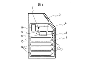
図1は、本発明の紙幣自動取引装置1(以下、ATM1)の構成の一例を示す概略図である。
図1において、ATM1は複数のモジュールから構成されており、図1には紙幣取扱装置2と入出力装置3とが示されている。紙幣取扱装置2は紙幣を取り扱う処理、例えば紙幣の入金や出金などの処理を行う。より詳細な構成と動作は後述する。入出力装置3は、例えばモニタとプッシュボタンの組み合わせや、両者を合わせたタッチパネルである。入出力装置3により、ATM1の操作者は入金や出金等の処理を選択して入力し、あるいは操作者へ操作手順の指示などを行う。他にも、カードを扱うモジュールや通帳を扱うモジュール、硬貨を扱うモジュールなどを備えることがある。
【0018】
紙幣を入金するとき、操作者は入出力装置3から入金処理を選択する。入出金口4のシャッターが開き、紙幣は束状で投入される。入出金口4は、ゴムを周設した繰り出しローラなどの機構により、紙幣を一枚ずつに分けて引き出して、搬送路5へ送り出す。搬送路5は、例えばベルトやローラなどから構成され、紙幣を挟み、ベルトやローラを移動・回転することにより、紙幣を搬送する。搬送される紙幣は、鑑別部6において、紙幣の光学的あるいは磁気的特徴などを取得し、真偽を判定する。
ここで、偽券あるいは破損した紙幣などの取引に不適であると判定された紙幣は、ゲート7を切り替えて、入出金口4へ返却される。
一方、取引可能と判定された紙幣は、一時集積部8へ収納される。操作者と入出力装置3との間で、金額の確認等がされた後、一時集積部8から紙幣を引き出して、搬送路5を介し、集積部9へ搬送する。集積部9が複数ある場合、ゲート7を切り替えて、例えば金種ごとに紙幣を収納する。
【0019】
一方、紙幣を出金するとき、操作者は入出力装置3で出金処理を選択する。集積部9は指示された枚数の紙幣を引き出して、搬送路5へ送り出す。鑑別部6を通過する際に、紙幣が出金に不適当であると判定された場合、ゲート7を切り替えて一時集積部8に収納する。適当である紙幣は入出金口4へ収納する。所定の枚数を収納した後、入出金口4のシャッターを開いて、紙幣を操作者へ渡す状態にする。また、不適当であると判断された紙幣Bは一時集積部8から引き出して、リジェクト集積部10へ収納する。
【0020】
ATM1は、以上に示した概略の動作により、入金および出金処理を行う。
このようなATM1において、本発明は紙幣の情報、例えば光学的な画像や磁気的なパターンを取得する鑑別部6に適用できる。
【0021】
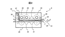
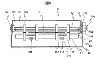
図2、図3は鑑別部6の構成例を示すものであり、図2は鑑別部6を紙幣搬送方向の側面から、図3は図2の矢印イに示す搬送方向から見た構成を示している。
図2、図3において、紙幣21は第1の案内手段22と第2の案内手段23とに挟まれた搬送空間を、第1の搬送手段24や第2の搬送手段25により搬送される。可動案内手段26は、搬送空間に突出して、紙幣21に搬送力を与えつつ、紙幣21を所定の方向へ案内する。
第1の案内手段22と第2の案内手段23は、例えば金属や樹脂の板材からなり、互いに所定の間隔を離して固定的に設けられている。
第1の搬送手段24と第2の搬送手段25は、例えば対向して押し付けられた一対のローラからなる。具体的な構成例を図3に示してある。第1の搬送手段24は駆動ローラ24aと従動ローラ24bとからなる。駆動ローラ24aはシャフト101と、シャフト101を回転自由に支持するベアリング102と、ゴムローラ103と、シャフトを軸方向に固定する止め輪104と、駆動力を伝達するギア105とからなる。従動ローラ24bは、外輪を搬送に利用したベアリング111と、ベアリング111を支持するシャフト112と、一端を第2の案内手段23に固定されてシャフト112を付勢するバネ113とからなる。
【0022】
駆動ローラ24aは、図示しないモータから駆動力をギア105で受け取り回転する。また、従動ローラ24bは、バネ113により駆動ローラ24aに押し付けられる。それらにより、紙幣21は、駆動ローラ24aと従動ローラ24bとに挟まれ、ゴムローラ103から駆動力をうけることにより搬送される。
【0023】
可動案内手段26は、第1の搬送手段24の駆動ローラ24aと同様の構成であり、対向する第2の案内手段23と所定の間隔を開けてあるいは接触して設けられる。可動案内手段26は搬送方向に搬送力を生じるようにローラが回転動作する。そのため、可動案内手段26と第2の案内手段23との間隔は、第1の案内手段22と第2の案内手段23との間隔より小さくできる。それにより、紙幣21を第3の情報取得手段33に近づけることができる。
【0024】
第1の筐体27と第2の筐体28は、第1の案内手段22や第2の案内手段23、第1の搬送手段24、第2の搬送手段25、可動案内手段26などを支持し、鑑別部6の外形を形成する。第1の筐体27と第2の筐体28は支点ロで回転自由に支持され、保守時に搬送空間を開放できるような構成になっている。
【0025】
第1の通過検知手段29と第2の通過検知手段30は、例えば搬送空間を挟んで対向して設けられた一対のフォトダイオードとフォトトランジスタであり、紙幣21により光軸が遮られることにより、鑑別部6に進入する紙幣21を検出する。
【0026】
第1の情報取得手段31と第2の情報取得手段32と第3の情報取得手段33は、搬送空間に近接して設けられ、紙幣21の光学的あるいは磁気的情報を取得するものである。第1の情報取得手段31と第2の情報取得手段32は、例えば光学的情報取得手段であり、発光ダイオード等の発光素子により紙幣21を照光し、その反射光をCCD等の受光素子で検出することにより、紙幣21の画像を取得する。第1の情報取得手段31と第2の情報取得手段32は搬送空間を挟んで対向して設けることにより、紙幣21の表裏の光学的画像を一度の通過で読み取ることができる。
【0027】
第3の情報取得手段33は、例えば磁気的情報取得手段であり、磁気検出素子により、紙幣21の磁気の強度パターンを取得することができる。
【0028】
ATM1においては、紙幣という有価物を取り扱うために、金種判別や真贋判定に極めて高い信頼性が要求される。そのため、鑑別部6では紙幣の情報を正確に取得する必要がある。
【0029】
図4は、従来の鑑別部6の搬送路構成を示す図である。
図4において、第1の搬送手段24において、駆動ローラ24aと従動ローラ24bの回転中心を結ぶ線を挟持方向線ハ1とする。第2の搬送手段25においても、駆動ローラ25aと従動ローラ25bの回転中心を結ぶ線を同様に挟持方向線ハ2とする。
一方、第1の案内手段22と第2の案内手段23に平行であり、第1の搬送手段24あるいは第2の搬送手段25が紙幣を挟持する点を通過する面を搬送面ニとする。
また、情報取得手段として光学的な情報取得手段を例としており、第1の情報取得手段31と第2の情報取得手段32はともに、少なくとも発光素子121と受光素子122とを備えている。発光素子121から照射した光は、矢印ホのように、紙幣21で反射して受光素子122に到達する。
【0030】
ここで、従来の鑑別部6は図示のように、挟持方向線ハ1と挟持方向線ハ2が搬送面ニに対して直交するように構成されており、紙幣21はほぼ搬送面ニに沿って搬送されるように設計されている。
しかしながら、実際には紙幣21に働く重力や紙幣21の周辺の空気からの抵抗力、あるいは紙幣21自体が平坦でなく折れや湾曲、しわなどの形状を持つことにより、紙幣21は搬送面ニから外れることが多い。
【0031】
そのため、紙幣21と第1の情報取得手段31や第2の情報取得手段32との距離が1枚の紙幣21が通過する間に逐次変化する。一方、発光素子121の照光や受光素子122の焦点は、一般的に搬送面ニを基準にしており、搬送面ニから外れると光度が低下したり、画像が不鮮明になったりする。そのため、1枚の紙幣21の画像の中に、本来の紙幣21に無い明暗や模様のぼやけが生じる。 また、情報取得手段が磁気的情報取得手段であった場合は、距離が離れるにつれ磁気の感度が低下するため、本来の紙幣21に無い磁気の強弱を検出することになる。
このような情報取得手段と紙幣との距離に由来する検出誤差は、金種判別や真贋判定の信頼性を低下させる。
【0032】
そこで、情報取得手段と紙幣との距離を一定にすることを目的として、図5に示す構成とした。
図5は、本発明の一実施例を備えた鑑別部6の搬送路構成を示す図である。 図5において、挟持方向線ハ1と挟持方向線ハ2が、側面から見て互いに逆向きの傾斜角度になるように、角度α1とα2傾けている。それにより、紙葉類21は第2の案内手段23に近づくように搬送される。第1の搬送手段24と第1の情報取得手段31との間における第2の案内手段23を領域Sとすると、角度α1が所定の角度以上であれば、紙幣21は第1の情報取得手段31に到達する以前に、領域Sの範囲で第2の案内手段23に接触し、第2の案内手段23に沿って搬送される。それにより、第1の情報取得手段31と紙幣21との距離をほぼ一定に保つことができる。
【0033】
すなわち、第2の情報取得手段32から駆動ローラ24aや駆動ローラ25aまでの距離を、第1の情報取得手段31から従動ローラ24bや従動ローラ25bまでの距離より、それぞれ近づければ、紙幣21は第1の情報取得手段31側の第2の案内手段23に沿って搬送される。
あるいは、第1の情報取得手段31から従動ローラ24bや従動ローラ25bまでの距離を、第2の情報取得手段32から駆動ローラ24aや駆動ローラ25aまでの距離より、それぞれ近づければ、紙幣21は第2の情報取得手段32側の第1の案内手段22に沿って搬送される。
【0034】
ここで、図5にしめすように搬送面ニが概略直線である場合、角度αの所定の角度とは、Lが搬送手段の挟持点から情報取得手段の検出位置までの搬送方向の距離、hが搬送手段の挟持点から情報取得手段の検出位置における案内手段までの搬送直交方向の距離とすると、
α≧tan−1(h/L)
【式1】
で表すことができる。図5においては、角度α1は式2で表される。なお、L1は第1の搬送手段24の挟持点から第1の情報取得手段31の検出位置までの搬送方向の距離、h2は第1の搬送手段24の挟持点から第1の情報取得手段31の検出位置における第2の案内手段23までの搬送直交方向の距離である。
【0035】
α1≧tan−1(h2/L1)
【式2】
同様に、角度α2は式3で表される。なお、L2は第2の搬送手段24の挟持点から第1の情報取得手段31の検出位置までの搬送方向の距離である。
【0036】
α2≧tan-1(h2/L2)
【式3】
ただし、角度αが過度に大きいと、紙葉類21と第2の案内手段23との摩擦力が大きくなり、ジャム等の搬送障害が発生する可能性がある。したがって、紙葉類21と第2の案内手段23との摩擦係数をμpgとすると、
![]()
【0037】
また、図6に示すように、第1の情報取得手段31の情報取得位置における搬送面ニとの直交線ハ3と、挟持方向線ハ1あるいは挟持方向線ハ2とが交差する構成と表すことができる。
【0038】
ここで、搬送面ニから交点までの距離をJとすると、
J<L 2 /h
【式5】
と表すことができる。また、角度αが過度に大きいときに搬送障害が生じうることは上述の通りであり、【式4】に示した範囲とする必要がある。
【0039】
なお、第2の搬送手段25の挟持方向線ハ2も傾けることが重要である。
これは、図7に示すように、紙幣21が搬送されていき、第2の搬送手段25に挟持された以降において、紙幣21を第1の情報取得手段31へ押し付ける力が生じるためである。
【0040】
また、上述の例においては挟持方向線ハを傾けていたが、図8に示す構成でも実施できる。
図8において、第1の搬送手段24と第2の搬送手段25を構成する一方のローラを他方に比べて柔らかくすることにより、紙葉類21の搬送方向線トを領域Sへ導くことができる。
【0041】
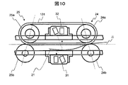
また、上述の例において、第1の搬送手段24と第2の搬送手段25は一対のローラから構成されていたが、図9あるいは図10に示すように、紙幣21をベルト131で搬送するものであっても良い。この構成においても、第1の搬送手段24と第2の搬送手段25のそれぞれにおいて、第1の情報取得手段31近傍の挟持方向線ハ1とハ2の角度α1とα2は、前述の式1で表される関係とすればよい。
【0042】
このように、情報取得手段に近接した両側の挟持方向線を、搬送に直交する角度から互いに逆向きの角度で傾けることにより、紙幣を一方の案内手段に押し付け、情報取得手段と紙幣との距離を一定に保つことができる。
なお、第1の案内手段22や第2の案内手段23が、プラスチックなどの抵抗率が高い素材の場合、紙幣21との接触によって静電気を生じることがある。それにより、静電気により塵埃を吸着して、情報取得に悪影響を与える可能性もある。
【0043】
そこで、第1の案内手段22や第2の案内手段23には、比較的に体積抵抗率の低く(1012Ωm以下)かつ光が透過する素材を用いることが望ましい。
また、第1の案内手段22や第2の案内手段23の全てをその素材にするとコスト高になることがあるため、図5に示すように、第1の情報取得手段31や第2の情報取得手段32の検知位置に光を透過して体積抵抗率が低い案内部材123を設け、それに接してアース接地された導電部材124を設けることが望ましい。
【0044】
これにより、検知位置における塵埃の吸着を防ぐことができる。
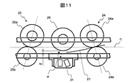
さらに、図11に示されるように、可動案内手段26を用いる場合においても、本構成を併用すると良い効果が得られる。これは、例えば磁気的情報取得手段や片側の光学的情報のみを取得すればよい場合のように、情報取得手段を搬送空間の片側だけに設けるとき、情報取得手段に対向して可動案内手段26を設けるものである。
【0045】
前述の通り、挟持方向線を傾けることにより、紙幣21を第3の情報取得手段33へ近接して搬送することができる。また、可動案内手段26と第2の案内手段23との間チへ、滑らかに紙幣21を送り込むことができる。
加えて可動案内手段26は、紙幣21に過度の折れ等があるために、紙幣21が第2の案内手段23から離れるような力を生じる場合においても、第2の案内手段との距離trの範囲に紙幣21を留めることができる。
【0046】
それにより、情報取得手段と紙幣との距離を一定に保つことができる。
【0047】
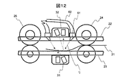
また、同様な効果を持つ構成として、図12に示す空気の流れを利用したものがある。
【0048】
ここでは、第1の情報取得手段31に相対した第1の案内手段22に吹き出し口61を設け、供給管62を通じて図示しないブロアから空気を供給することにより、矢印リで示すように紙幣21へ空気を吹き付ける構成を示している。それにより、紙幣21は第2の案内手段22へ押し付けられて搬送されるため、第1の情報取得手段31や第2の情報取得手段32から紙幣21までの距離を一定に保つことができる。
【0049】
さらに、図13に示すように、第1の情報取得手段31や第2の情報取得手段32から紙幣21までの距離hcを測定して、発光素子121や受光素子122を制御する構成がある。
【0050】
図13において、距離測定手段71は紙幣21との距離hcを測定するものであり、例えば超音波を用いて反射時間により測定するものやレーザを用いて照射位置から三角測量により距離を測定するものなどがある。
【0051】
制御手段72は、距離測定手段71から距離hcを受け取り、発光素子121や受光素子122を制御するものである。
【0052】
発光素子121から照射される光は、その光軸中央で最も明るく、中央から外れるに従い暗くなる。紙幣21が搬送面ニを通過することを基準とした場合、搬送面ニから離れるに従い、受光素子122が検出している紙幣21の対象部分は暗くなる。
【0053】
そこで、制御方法としては、距離hcに応じて発光素子121への電流を制御して光量を変化させる。距離hcと電流との関係は予め定義して制御手段72に組み込んでおくものとする。それにより、紙幣21の検出対象部分の明るさは一定に保たれ、1枚の紙幣21の中で、光度の変化が生じない。
【0054】
以上に示した構成により、紙幣と情報取得手段との距離を一定に保ち、情報を正確に取得することにより、信頼性の高い金種判別や真贋判定を行うことができる。
【0055】
【発明の効果】
本発明によれば、紙幣と情報取得手段との距離を一定に保ち、情報を正確に取得することにより、信頼性の高い金種判別や真贋判定が可能な紙葉類搬送装置を提供できる。
【図面の簡単な説明】
【図1】図1は、紙幣自動取引装置の概略構成図である。
【図2】図2は、鑑別部の概略構成図である。
【図3】図3は、鑑別部の概略構成図である。
【図4】図4は、従来の鑑別部構成の模式図である。
【図5】図5は、本発明の鑑別部構成の模式図である。
【図6】図6は、本発明の鑑別部構成の模式図である。
【図7】図7は、本発明の鑑別部構成の模式図である。
【図8】図8は、本発明の鑑別部構成の模式図である。
【図9】図9は、本発明の鑑別部構成の模式図である。
【図10】図10は、本発明の鑑別部構成の模式図である。
【図11】図11は、本発明の鑑別部構成の模式図である。
【図12】図12は、本発明の鑑別部構成の模式図である。
【図13】図13は、本発明の鑑別部構成の模式図である。
【符号の説明】
1…紙幣自動取引装置、2…紙幣取扱装置、3…入出力装置、4…入出金口、5…搬送路、6…鑑別部、7…ゲート、8…一時集積部、9…集積部、10…リジェクト集積部、21…紙幣、22…第1の案内手段、23…第2の案内手段、24…第1の搬送手段、25…第2の搬送手段、26…可動案内手段、27…第1の筐体、28…第2の筐体、29…第1の通過検知手段、30…第2の通過検知手段、31…第1の情報取得手段、32…第2の情報取得手段、33…第3の情報取得手段、71…距離測定手段、121…発光素子、122…受光素子、123…案内部材、124…導電部材、131…ベルト。[0001]
BACKGROUND OF THE INVENTION
The present invention relates to a paper sheet transport apparatus that transports a thin medium such as paper sheets and acquires information attached to the medium.
[0002]
[Prior art]
As a conventional paper sheet conveying apparatus having an information acquisition function, for example, there is a paper sheet discrimination apparatus disclosed in Japanese Patent Application Laid-Open No. 2000-25985.
In this prior art, a configuration for determining the surface state of a paper sheet is shown, and a bill is sandwiched and conveyed by rollers before and after the detection unit.
[0003]
Japanese Patent Application Laid-Open No. 2000-90318 describes a paper sheet and a method for determining the paper sheet, and has a configuration in which a coupon ticket, a voting ticket, or the like is held between rollers before and after an image sensor.
[Patent Document 1]
JP 2000-259885 A [Patent Document 2]
Japanese Patent Laid-Open No. 2000-90318
[Problems to be solved by the invention]
In a paper sheet transport apparatus that acquires information, there is a problem that the distance between the paper sheet and the information acquisition means must be kept constant.
For example, in the case of an optical information acquisition means, when the distance from the paper sheet changes, a focus shift or illumination brightness may occur. In the case of magnetic information acquisition means, the sensitivity decreases as the paper leaves from the magnetic detection sensor. As a result, the information on the paper sheets cannot be obtained accurately.
[0005]
An object of the present invention is to provide a paper sheet transport device capable of highly reliable denomination and authenticity determination by keeping the distance between a bill and an information acquisition unit constant and acquiring information accurately. It is in.
[0006]
[Means for Solving the Problems]
The object is to provide first and second transport means for transporting paper sheets, guide means for guiding the transport of paper sheets provided between the first and second transport means, information the paper sheet is formed from the second conveying means acquires the transfer space being conveyed therein, the information described the transport space in the paper sheet to be conveyed along said guide means In a paper sheet transport apparatus having an acquisition means, the first transport means and the second transport means have inclination angles opposite to each other so that the paper sheets are transported so as to approach the guide means. The paper sheet is conveyed to the guide means according to the inclination angle, and the distance between the information acquisition means and the paper sheet is kept constant .
[0007]
Further, the object is that the perpendicular line of the information acquisition means to the conveyance surface of the conveyance space intersects the clamping direction line of the first conveyance means or the clamping direction line of the second conveyance means. This is achieved by being provided.
[0008]
Further, the object is that one of the rollers constituting the first and second conveying means has a low rigidity compared to the other roller, and when the first conveying means is conveyed from the first conveying means side, When transporting from the second transport means side so that the leading edge of the paper sheet is guided between the transport means and the information acquisition means, the second transport means and the information acquisition means This is achieved by being configured such that the leading edge of the paper sheet is guided therebetween .
[0016]
DETAILED DESCRIPTION OF THE INVENTION
Below, the example applied to the automatic banknote transaction apparatus (henceforth, ATM) is shown as an example of embodiment of this invention.
[0017]
FIG. 1 is a schematic diagram illustrating an example of a configuration of an automatic bill transaction apparatus 1 (hereinafter, ATM1) according to the present invention.
In FIG. 1, ATM1 is comprised from the some module, and the
[0018]
When depositing a bill, the operator selects a deposit process from the input /
Here, banknotes determined to be unsuitable for transactions such as counterfeits or damaged banknotes are returned to the deposit / withdrawal port 4 by switching the
On the other hand, the banknote determined to be tradeable is stored in the
[0019]
On the other hand, when the banknote is withdrawn, the operator selects the withdrawal process with the input /
[0020]
The ATM 1 performs deposit and withdrawal processing according to the general operation described above.
In such ATM1, this invention is applicable to the
[0021]
2 and 3 show an example of the configuration of the
2 and 3, the
The first guide means 22 and the second guide means 23 are made of, for example, a metal or resin plate material, and are fixedly provided at a predetermined interval from each other.
The 1st conveyance means 24 and the 2nd conveyance means 25 consist of a pair of roller pressed facing, for example. A specific configuration example is shown in FIG. The
[0022]
The driving
[0023]
The movable guide means 26 has the same configuration as that of the
[0024]
The
[0025]
The first passage detection means 29 and the second passage detection means 30 are, for example, a pair of photodiodes and phototransistors provided facing each other with the conveyance space interposed therebetween. A
[0026]
The 1st information acquisition means 31, the 2nd information acquisition means 32, and the 3rd information acquisition means 33 are provided close to conveyance space, and acquire the optical or magnetic information of
[0027]
The 3rd information acquisition means 33 is magnetic information acquisition means, for example, and can acquire the magnetism intensity pattern of
[0028]
In ATM1, in order to handle valuables such as banknotes, extremely high reliability is required for denomination and authenticity determination. Therefore, it is necessary for the
[0029]
FIG. 4 is a diagram illustrating a conveyance path configuration of the
In FIG. 4, in the first conveying
On the other hand, a surface that is parallel to the
Further, an optical information acquisition unit is taken as an example of the information acquisition unit, and both the first
[0030]
Here, the
However, in actuality, the
[0031]
Therefore, the distance between the
Such a detection error derived from the distance between the information acquisition means and the banknote decreases the reliability of denomination discrimination and authenticity determination.
[0032]
Therefore, for the purpose of making the distance between the information acquisition means and the banknote constant, the configuration shown in FIG. 5 is adopted.
FIG. 5 is a diagram illustrating a conveyance path configuration of the
[0033]
That is, if the distance from the second
Alternatively, if the distance from the first
[0034]
Here, as shown in FIG. 5, when the conveyance surface D is a substantially straight line, the predetermined angle α is the distance in the conveyance direction from the clamping point of the conveyance means to the detection position of the information acquisition means, h Is the distance in the conveyance orthogonal direction from the clamping point of the conveyance means to the guide means at the detection position of the information acquisition means,
α ≧ tan −1 (h / L)
[Formula 1]
Can be expressed as In FIG. 5, the angle α1 is expressed by
[0035]
α1 ≧ tan −1 (h2 / L1)
[Formula 2]
Similarly, the angle α2 is expressed by
[0036]
α2 ≧ tan −1 (h2 / L2)
[Formula 3]
However, if the angle α is excessively large, the frictional force between the
![]()
[0037]
Further, as shown in FIG. 6, it is represented as a configuration in which the
[0038]
Here, when the distance from the conveyance surface D to the intersection is J,
J <L 2 / h
[Formula 5]
It can be expressed as. Further, as described above, when the angle α is excessively large, a conveyance failure may occur, and it is necessary to set the range in the following formula (4).
[0039]
It is important that the clamping direction line C2 of the second transport means 25 is also inclined.
This is because, as shown in FIG. 7, after the
[0040]
In the above-described example, the clamping direction line C is inclined, but the configuration shown in FIG. 8 can also be implemented.
In FIG. 8, by making one roller constituting the
[0041]
In the above example, the
[0042]
Thus, by tilting the holding direction lines on both sides close to the information acquisition means at angles opposite to each other from the angle orthogonal to the conveyance, the banknote is pressed against one guide means, and the distance between the information acquisition means and the banknote Can be kept constant.
In addition, when the 1st guide means 22 and the 2nd guide means 23 are materials with high resistivity, such as a plastics, static electricity may arise by contact with the
[0043]
Therefore, it is desirable to use a material having a relatively low volume resistivity (10 12 Ωm or less) and transmitting light for the first guiding means 22 and the second guiding means 23.
Further, since it may be expensive to use all of the first guide means 22 and the second guide means 23 as the material, as shown in FIG. 5, the first information acquisition means 31 and the second information are provided. It is desirable to provide a guide member 123 that transmits light at the detection position of the acquisition means 32 and has a low volume resistivity, and a conductive member 124 that is grounded in contact therewith.
[0044]
Thereby, adsorption | suction of the dust in a detection position can be prevented.
Furthermore, as shown in FIG. 11, even when the movable guide means 26 is used, a good effect can be obtained by using this configuration together. This is because the movable guide means 26 faces the information acquisition means when the information acquisition means is provided only on one side of the transport space, as in the case where only the magnetic information acquisition means or the optical information on one side needs to be acquired. Is provided.
[0045]
As described above, the
In addition, the movable guide means 26 has a distance tr with respect to the second guide means even when the
[0046]
Thereby, the distance of an information acquisition means and a banknote can be kept constant.
[0047]
Further, as a configuration having the same effect, there is a configuration using the air flow shown in FIG.
[0048]
Here, the
[0049]
Furthermore, as shown in FIG. 13, there is a configuration in which the
[0050]
In FIG. 13, the distance measuring means 71 measures the distance hc from the
[0051]
The control means 72 receives the distance hc from the distance measurement means 71 and controls the
[0052]
The light emitted from the
[0053]
Therefore, as a control method, the amount of light is changed by controlling the current to the
[0054]
With the configuration described above, highly reliable denomination and authenticity determination can be performed by keeping the distance between the banknote and the information acquisition means constant and acquiring the information accurately.
[0055]
【The invention's effect】
ADVANTAGE OF THE INVENTION According to this invention, the paper sheet conveyance apparatus in which a reliable denomination and authenticity determination can be provided by keeping the distance of a banknote and an information acquisition means constant, and acquiring information correctly can be provided.
[Brief description of the drawings]
FIG. 1 is a schematic configuration diagram of a bill automatic transaction apparatus.
FIG. 2 is a schematic configuration diagram of a discrimination unit.
FIG. 3 is a schematic configuration diagram of a discrimination unit.
FIG. 4 is a schematic diagram of a conventional discrimination unit configuration.
FIG. 5 is a schematic diagram of a configuration of a discrimination unit according to the present invention.
FIG. 6 is a schematic diagram of a configuration of a discrimination unit according to the present invention.
FIG. 7 is a schematic diagram of a configuration of a discrimination unit according to the present invention.
FIG. 8 is a schematic diagram of a configuration of a discrimination unit according to the present invention.
FIG. 9 is a schematic diagram of a configuration of a discrimination unit according to the present invention.
FIG. 10 is a schematic diagram of a configuration of a discrimination unit according to the present invention.
FIG. 11 is a schematic diagram of a configuration of a discrimination unit according to the present invention.
FIG. 12 is a schematic diagram of a configuration of a discrimination unit according to the present invention.
FIG. 13 is a schematic diagram of a configuration of a discrimination unit according to the present invention.
[Explanation of symbols]
DESCRIPTION OF SYMBOLS 1 ... Banknote automatic transaction apparatus, 2 ... Banknote handling apparatus, 3 ... Input / output device, 4 ... Deposit / withdrawal port, 5 ... Conveyance path, 6 ... Discrimination part, 7 ... Gate, 8 ... Temporary accumulation part, 9 ... Accumulation part, DESCRIPTION OF
Claims (3)
前記情報取得手段における前記搬送空間の搬送面との直交線と、前記第1の搬送手段の挟持方向線あるいは前記第2の搬送手段の挟持方向線とが交差するように設けられていることを特徴とする紙葉類搬送装置。In the paper sheet conveying apparatus according to claim 1,
It is provided that the orthogonal line with the conveyance surface of the conveyance space in the information acquisition unit intersects the clamping direction line of the first conveyance unit or the clamping direction line of the second conveyance unit. Characteristic paper sheet transport device.
前記第1と第2の搬送手段を構成する一方のローラが他方のローラと比較して低剛性であり、前記第1の搬送手段側から搬送するときは、前記第1の搬送手段と前記情報取得手段との間に前記紙葉類の先端が導かれるように、前記第2の搬送手段側から搬送するときは、前記第2の搬送手段と前記情報取得手段との間に前記紙葉類の先端が導かれるように構成されていることを特徴とする紙葉類搬送装置。In the paper sheet conveying apparatus according to claim 1,
One of the rollers constituting the first and second conveying means has a lower rigidity than the other roller, and when conveying from the first conveying means side, the first conveying means and the information When transporting from the second transport unit side so that the leading edge of the paper sheet is guided between the acquisition unit and the acquisition unit, the paper sheet is disposed between the second transport unit and the information acquisition unit. A paper sheet transporting device, wherein the leading end of the paper is guided.
Priority Applications (6)
| Application Number | Priority Date | Filing Date | Title |
|---|---|---|---|
| JP2003178859A JP4366122B2 (en) | 2003-06-24 | 2003-06-24 | Paper sheet transport device |
| KR1020040007719A KR100582611B1 (en) | 2003-06-24 | 2004-02-06 | Paper conveying device |
| US10/772,386 US8091888B2 (en) | 2003-06-24 | 2004-02-06 | Sheet handling apparatus |
| CNB2004100048416A CN100382111C (en) | 2003-06-24 | 2004-02-09 | Sheet handling apparatus |
| EP04002792A EP1492057B1 (en) | 2003-06-24 | 2004-02-09 | Sheet handling apparatus |
| DE602004029636T DE602004029636D1 (en) | 2003-06-24 | 2004-02-09 | Sheet conveying device |
Applications Claiming Priority (1)
| Application Number | Priority Date | Filing Date | Title |
|---|---|---|---|
| JP2003178859A JP4366122B2 (en) | 2003-06-24 | 2003-06-24 | Paper sheet transport device |
Publications (3)
| Publication Number | Publication Date |
|---|---|
| JP2005018177A JP2005018177A (en) | 2005-01-20 |
| JP2005018177A5 JP2005018177A5 (en) | 2008-04-03 |
| JP4366122B2 true JP4366122B2 (en) | 2009-11-18 |
Family
ID=33411049
Family Applications (1)
| Application Number | Title | Priority Date | Filing Date |
|---|---|---|---|
| JP2003178859A Expired - Fee Related JP4366122B2 (en) | 2003-06-24 | 2003-06-24 | Paper sheet transport device |
Country Status (6)
| Country | Link |
|---|---|
| US (1) | US8091888B2 (en) |
| EP (1) | EP1492057B1 (en) |
| JP (1) | JP4366122B2 (en) |
| KR (1) | KR100582611B1 (en) |
| CN (1) | CN100382111C (en) |
| DE (1) | DE602004029636D1 (en) |
Families Citing this family (28)
| Publication number | Priority date | Publication date | Assignee | Title |
|---|---|---|---|---|
| DE102005000698A1 (en) * | 2005-01-04 | 2006-07-13 | Giesecke & Devrient Gmbh | Examination of value documents |
| JP5018073B2 (en) | 2006-12-21 | 2012-09-05 | 富士ゼロックス株式会社 | Surface reader and object confirmation device |
| TWI329611B (en) * | 2007-04-02 | 2010-09-01 | Avision Inc | Sheet-conveying apparatus and method for detection of multiple documents thereof |
| JP2009067513A (en) * | 2007-09-12 | 2009-04-02 | Hitachi Omron Terminal Solutions Corp | Paper sheet storage device, and method and program for controlling the same |
| JP2009151703A (en) * | 2007-12-21 | 2009-07-09 | Laurel Precision Machines Co Ltd | Paper money processor |
| JP5122325B2 (en) * | 2008-02-26 | 2013-01-16 | 日立オムロンターミナルソリューションズ株式会社 | Paper sheet transport mechanism and paper sheet handling device |
| JP5140631B2 (en) * | 2009-05-21 | 2013-02-06 | 京セラドキュメントソリューションズ株式会社 | Image forming apparatus |
| TWI363701B (en) * | 2009-09-18 | 2012-05-11 | Avision Inc | Sheet transporting apparatus having a gear assembly for fixing position of rotating shaft |
| JP5558288B2 (en) | 2010-09-16 | 2014-07-23 | 株式会社東芝 | Paper sheet inspection device |
| FR2984774B1 (en) * | 2011-12-23 | 2014-02-14 | Solystic | FLAT OBJECT SORTING MACHINE HAVING HETEROGENEOUS PHYSICAL CHARACTERISTICS, AND METHOD OF SORTING THESE FLAT OBJECTS |
| CN102760322B (en) * | 2012-06-18 | 2014-08-20 | 广州广电运通金融电子股份有限公司 | Data acquisition device for tear and fold tickets |
| JP5404870B1 (en) | 2012-08-24 | 2014-02-05 | 株式会社Pfu | Paper reading device, jam determination method, and computer program |
| JP5404872B1 (en) | 2012-08-24 | 2014-02-05 | 株式会社Pfu | Paper transport device, multifeed judgment method, and computer program |
| JP2015037982A (en) | 2012-08-24 | 2015-02-26 | 株式会社Pfu | Manuscript transport device, jam determination method and computer program |
| JP5404876B1 (en) | 2012-08-24 | 2014-02-05 | 株式会社Pfu | Paper transport device, jam determination method, and computer program |
| JP5404880B1 (en) * | 2012-09-14 | 2014-02-05 | 株式会社Pfu | Paper transport device, abnormality determination method, and computer program |
| JP6087763B2 (en) * | 2013-08-20 | 2017-03-01 | 株式会社東芝 | Paper sheet identification device and paper sheet processing device |
| JP2015041161A (en) * | 2013-08-20 | 2015-03-02 | 株式会社東芝 | Paper sheet identification device and paper sheet processing device |
| EP2843631B1 (en) * | 2013-08-20 | 2019-05-22 | Kabushiki Kaisha Toshiba | Sheet discriminating device and sheet processing apparatus |
| KR101607380B1 (en) * | 2014-04-23 | 2016-03-29 | 주식회사 엘지씨엔에스 | Media recognizing apparatus and financial device |
| CN103927813B (en) * | 2014-04-24 | 2016-05-25 | 中国人民银行印制科学技术研究所 | Flaky material imaging device and use the cleaning-sorting machine of this device |
| CN103996237B (en) * | 2014-05-16 | 2017-01-11 | 威海华菱光电股份有限公司 | Sheet detection device and image reading device |
| CN103996236B (en) * | 2014-05-16 | 2017-08-01 | 威海华菱光电股份有限公司 | Thin slice detection means and image read-out |
| KR101640984B1 (en) * | 2014-06-30 | 2016-07-19 | 주식회사 엘지씨엔에스 | Medium sensing apparatus and financial device |
| JP6409525B2 (en) * | 2014-11-21 | 2018-10-24 | 沖電気工業株式会社 | Antistatic mechanism and medium transaction device |
| US10375901B2 (en) | 2014-12-09 | 2019-08-13 | Mtd Products Inc | Blower/vacuum |
| CN107393136B (en) * | 2017-08-14 | 2023-08-01 | 昆山古鳌电子机械有限公司 | Paper money conveying device |
| DE102020004285A1 (en) * | 2020-07-16 | 2022-01-20 | Giesecke+Devrient Currency Technology Gmbh | Device for processing documents of value |
Family Cites Families (34)
| Publication number | Priority date | Publication date | Assignee | Title |
|---|---|---|---|---|
| US3276425A (en) * | 1963-09-05 | 1966-10-04 | Addressograph Multigraph | Copying machine |
| CH582612A5 (en) * | 1974-09-24 | 1976-12-15 | Gretag Ag | |
| US3966047A (en) * | 1974-11-27 | 1976-06-29 | Rowe International Inc. | Paper currency acceptor |
| US4015730A (en) * | 1975-11-24 | 1977-04-05 | J. I. Case Company | Adjustable boom for material handling implement |
| US4280036A (en) * | 1978-10-24 | 1981-07-21 | Tokyo Shibaura Denki Kabushiki Kaisha | Banking apparatus using passbooks |
| US4567349A (en) * | 1982-11-15 | 1986-01-28 | Xerox Corporation | Heat and pressure fuser apparatus |
| JPS62196251A (en) | 1986-02-21 | 1987-08-29 | Nec Corp | Skew compensator in conveyor for paper sheet |
| US5240116A (en) * | 1986-09-05 | 1993-08-31 | Opex Corporation | Method and apparatus for determining the orientation of a document |
| DE8700258U1 (en) * | 1987-01-07 | 1988-05-05 | Irbit Research + Consulting Ag, Freiburg/Fribourg, Ch | |
| JPS6483182A (en) * | 1987-09-25 | 1989-03-28 | Toshiba Corp | Optical detector |
| US4993700A (en) * | 1988-11-15 | 1991-02-19 | Brandt, Inc. | Facing mechanism for sheet feeder |
| JPH033844A (en) * | 1989-05-30 | 1991-01-09 | Hitachi Ltd | Paper sheet handling mechanism |
| US5295196A (en) * | 1990-02-05 | 1994-03-15 | Cummins-Allison Corp. | Method and apparatus for currency discrimination and counting |
| US6311819B1 (en) * | 1996-05-29 | 2001-11-06 | Cummins-Allison Corp. | Method and apparatus for document processing |
| US5245897A (en) * | 1991-11-25 | 1993-09-21 | E. I. Du Pont De Nemours And Company | System and method for advancing the leading edge of a corrugated web |
| JP3006323B2 (en) * | 1992-11-27 | 2000-02-07 | 松下電器産業株式会社 | Banknote recognition device |
| JPH0896203A (en) * | 1994-09-29 | 1996-04-12 | Shibaura Eng Works Co Ltd | Paper money recognition device |
| GB2293649B (en) * | 1994-09-29 | 1998-11-04 | Mars Inc | Apparatus for handling value sheets |
| ES2106672B1 (en) | 1994-12-23 | 1998-06-01 | Azkoyen Ind Sa | METHOD AND APPARATUS FOR THE CHARACTERIZATION AND DISCRIMINATION OF TICKETS AND LEGAL COURSE DOCUMENTS. |
| US5486063A (en) * | 1995-01-09 | 1996-01-23 | Intermec Incorporated | Method and apparatus for sensing the length of label or tag media by detecting changes in relative thickness |
| US5934140A (en) * | 1996-06-19 | 1999-08-10 | Xerox Corporation | Paper property sensing system |
| US5809885A (en) * | 1996-09-09 | 1998-09-22 | Druckmaschinenwerk Planeta | Blower for printing presses for assisting in the guidance of sheets |
| JP2000090318A (en) | 1998-09-08 | 2000-03-31 | Nippon Totor Co Ltd | Paper sheets and its discrimination method |
| JP2000090317A (en) | 1998-09-08 | 2000-03-31 | Nippon Totor Co Ltd | Paper sheets reader |
| JP2000259885A (en) | 1999-03-10 | 2000-09-22 | Hamamatsu Photonics Kk | Paper sheets discrimination device |
| JP2000268225A (en) | 1999-03-16 | 2000-09-29 | Toshiba Corp | Paper sheets discrimination device |
| DE60139429D1 (en) * | 2000-02-16 | 2009-09-10 | Smithkline Beecham Plc | Pyrimidine-5-onderivatives as LDL-PLA2 inhibitors |
| GB0018972D0 (en) * | 2000-08-02 | 2000-09-20 | Rue De Int Ltd | Document handling system |
| JP3849913B2 (en) * | 2000-10-05 | 2006-11-22 | 日立オムロンターミナルソリューションズ株式会社 | Paper sheet handling equipment |
| JP4374143B2 (en) | 2000-10-20 | 2009-12-02 | 日立オムロンターミナルソリューションズ株式会社 | Banknote discriminating apparatus and banknote automatic transaction apparatus provided with banknote discriminating apparatus |
| JP4143602B2 (en) * | 2002-06-04 | 2008-09-03 | キヤノン株式会社 | Double feed detection method, double feed detection apparatus, image forming apparatus, and image reading apparatus |
| US6668155B1 (en) * | 2002-07-23 | 2003-12-23 | Xerox Corporation | Lead edge paper curl sensor |
| JP4954439B2 (en) * | 2002-10-21 | 2012-06-13 | ハイデルベルガー ドルツクマシーネン アクチエンゲゼルシヤフト | Sheet processing machine with pneumatic sheet guide device |
| JP4503999B2 (en) * | 2002-12-12 | 2010-07-14 | ハイデルベルガー ドルツクマシーネン アクチエンゲゼルシヤフト | Sheet guide device |
-
2003
- 2003-06-24 JP JP2003178859A patent/JP4366122B2/en not_active Expired - Fee Related
-
2004
- 2004-02-06 US US10/772,386 patent/US8091888B2/en not_active Expired - Fee Related
- 2004-02-06 KR KR1020040007719A patent/KR100582611B1/en not_active IP Right Cessation
- 2004-02-09 EP EP04002792A patent/EP1492057B1/en not_active Expired - Fee Related
- 2004-02-09 DE DE602004029636T patent/DE602004029636D1/en not_active Expired - Lifetime
- 2004-02-09 CN CNB2004100048416A patent/CN100382111C/en not_active Expired - Fee Related
Also Published As
| Publication number | Publication date |
|---|---|
| EP1492057B1 (en) | 2010-10-20 |
| KR20050004682A (en) | 2005-01-12 |
| EP1492057A2 (en) | 2004-12-29 |
| KR100582611B1 (en) | 2006-05-23 |
| JP2005018177A (en) | 2005-01-20 |
| CN1573818A (en) | 2005-02-02 |
| CN100382111C (en) | 2008-04-16 |
| EP1492057A3 (en) | 2006-01-11 |
| US8091888B2 (en) | 2012-01-10 |
| US20040262836A1 (en) | 2004-12-30 |
| DE602004029636D1 (en) | 2010-12-02 |
Similar Documents
| Publication | Publication Date | Title |
|---|---|---|
| JP4366122B2 (en) | Paper sheet transport device | |
| US6241244B1 (en) | Document sensor for currency recycling automated banking machine | |
| USRE43358E1 (en) | Data reading apparatus | |
| JP4374143B2 (en) | Banknote discriminating apparatus and banknote automatic transaction apparatus provided with banknote discriminating apparatus | |
| TWI299839B (en) | Sheet identification machine | |
| US7607662B2 (en) | Bill handling apparatus | |
| JPH06203248A (en) | Code recording device of paper sheet or the like | |
| JP2003044900A (en) | Automatic transaction machine for paper money au | |
| US7124935B2 (en) | Check multifeed detection apparatus for use in a check processing terminal and detection method | |
| EP2843631B1 (en) | Sheet discriminating device and sheet processing apparatus | |
| WO2015174290A1 (en) | Thickness detection device, and medium transaction device | |
| WO2016141801A1 (en) | Image sensor and banknote processing apparatus | |
| JP7419735B2 (en) | Media identification device and media handling device | |
| US7708273B2 (en) | Paper sheet processing apparatus | |
| JP4095855B2 (en) | Paper sheet information acquisition device | |
| US20190340863A1 (en) | Value Note Cassette | |
| JP2019204377A (en) | Thickness detection device and medium transaction device | |
| JPWO2004023405A1 (en) | Paper sheet processing equipment | |
| JP2641275B2 (en) | Paper sheet stacking and feeding device | |
| US11066265B2 (en) | Value note cassette | |
| JP2009252209A (en) | Paper sheet handling device | |
| EP1510839A1 (en) | An optical detector and method of operation thereof | |
| JPH1159973A (en) | Document taking-in device | |
| JPH0736262U (en) | Bill validator | |
| JP2018195188A (en) | Medium discrimination device and medium processing device |
Legal Events
| Date | Code | Title | Description |
|---|---|---|---|
| A711 | Notification of change in applicant |
Free format text: JAPANESE INTERMEDIATE CODE: A712 Effective date: 20050223 |
|
| A521 | Request for written amendment filed |
Free format text: JAPANESE INTERMEDIATE CODE: A523 Effective date: 20060324 |
|
| A621 | Written request for application examination |
Free format text: JAPANESE INTERMEDIATE CODE: A621 Effective date: 20060324 |
|
| A521 | Request for written amendment filed |
Free format text: JAPANESE INTERMEDIATE CODE: A523 Effective date: 20060324 |
|
| RD02 | Notification of acceptance of power of attorney |
Free format text: JAPANESE INTERMEDIATE CODE: A7422 Effective date: 20060511 |
|
| RD04 | Notification of resignation of power of attorney |
Free format text: JAPANESE INTERMEDIATE CODE: A7424 Effective date: 20060511 |
|
| A521 | Request for written amendment filed |
Free format text: JAPANESE INTERMEDIATE CODE: A523 Effective date: 20080214 |
|
| A977 | Report on retrieval |
Free format text: JAPANESE INTERMEDIATE CODE: A971007 Effective date: 20080926 |
|
| A131 | Notification of reasons for refusal |
Free format text: JAPANESE INTERMEDIATE CODE: A131 Effective date: 20081007 |
|
| A521 | Request for written amendment filed |
Free format text: JAPANESE INTERMEDIATE CODE: A523 Effective date: 20081204 |
|
| A131 | Notification of reasons for refusal |
Free format text: JAPANESE INTERMEDIATE CODE: A131 Effective date: 20090609 |
|
| A521 | Request for written amendment filed |
Free format text: JAPANESE INTERMEDIATE CODE: A523 Effective date: 20090626 |
|
| TRDD | Decision of grant or rejection written | ||
| A01 | Written decision to grant a patent or to grant a registration (utility model) |
Free format text: JAPANESE INTERMEDIATE CODE: A01 Effective date: 20090804 |
|
| A01 | Written decision to grant a patent or to grant a registration (utility model) |
Free format text: JAPANESE INTERMEDIATE CODE: A01 |
|
| A61 | First payment of annual fees (during grant procedure) |
Free format text: JAPANESE INTERMEDIATE CODE: A61 Effective date: 20090824 |
|
| FPAY | Renewal fee payment (event date is renewal date of database) |
Free format text: PAYMENT UNTIL: 20120828 Year of fee payment: 3 |
|
| R150 | Certificate of patent or registration of utility model |
Free format text: JAPANESE INTERMEDIATE CODE: R150 |
|
| FPAY | Renewal fee payment (event date is renewal date of database) |
Free format text: PAYMENT UNTIL: 20130828 Year of fee payment: 4 |
|
| LAPS | Cancellation because of no payment of annual fees |