JP4365909B2 - Pulse inversion Doppler ultrasonic diagnostic image processing method and apparatus - Google Patents
Pulse inversion Doppler ultrasonic diagnostic image processing method and apparatus Download PDFInfo
- Publication number
- JP4365909B2 JP4365909B2 JP28139398A JP28139398A JP4365909B2 JP 4365909 B2 JP4365909 B2 JP 4365909B2 JP 28139398 A JP28139398 A JP 28139398A JP 28139398 A JP28139398 A JP 28139398A JP 4365909 B2 JP4365909 B2 JP 4365909B2
- Authority
- JP
- Japan
- Prior art keywords
- ultrasonic
- image processing
- doppler
- ultrasound
- diagnostic image
- Prior art date
- Legal status (The legal status is an assumption and is not a legal conclusion. Google has not performed a legal analysis and makes no representation as to the accuracy of the status listed.)
- Expired - Fee Related
Links
Images


Classifications
-
- G—PHYSICS
- G01—MEASURING; TESTING
- G01S—RADIO DIRECTION-FINDING; RADIO NAVIGATION; DETERMINING DISTANCE OR VELOCITY BY USE OF RADIO WAVES; LOCATING OR PRESENCE-DETECTING BY USE OF THE REFLECTION OR RERADIATION OF RADIO WAVES; ANALOGOUS ARRANGEMENTS USING OTHER WAVES
- G01S7/00—Details of systems according to groups G01S13/00, G01S15/00, G01S17/00
- G01S7/52—Details of systems according to groups G01S13/00, G01S15/00, G01S17/00 of systems according to group G01S15/00
- G01S7/52017—Details of systems according to groups G01S13/00, G01S15/00, G01S17/00 of systems according to group G01S15/00 particularly adapted to short-range imaging
- G01S7/52023—Details of receivers
- G01S7/52036—Details of receivers using analysis of echo signal for target characterisation
- G01S7/52038—Details of receivers using analysis of echo signal for target characterisation involving non-linear properties of the propagation medium or of the reflective target
-
- A—HUMAN NECESSITIES
- A61—MEDICAL OR VETERINARY SCIENCE; HYGIENE
- A61B—DIAGNOSIS; SURGERY; IDENTIFICATION
- A61B8/00—Diagnosis using ultrasonic, sonic or infrasonic waves
- A61B8/48—Diagnostic techniques
- A61B8/481—Diagnostic techniques involving the use of contrast agent, e.g. microbubbles introduced into the bloodstream
-
- G—PHYSICS
- G01—MEASURING; TESTING
- G01S—RADIO DIRECTION-FINDING; RADIO NAVIGATION; DETERMINING DISTANCE OR VELOCITY BY USE OF RADIO WAVES; LOCATING OR PRESENCE-DETECTING BY USE OF THE REFLECTION OR RERADIATION OF RADIO WAVES; ANALOGOUS ARRANGEMENTS USING OTHER WAVES
- G01S15/00—Systems using the reflection or reradiation of acoustic waves, e.g. sonar systems
- G01S15/02—Systems using the reflection or reradiation of acoustic waves, e.g. sonar systems using reflection of acoustic waves
- G01S15/06—Systems determining the position data of a target
- G01S15/08—Systems for measuring distance only
- G01S15/10—Systems for measuring distance only using transmission of interrupted, pulse-modulated waves
- G01S15/102—Systems for measuring distance only using transmission of interrupted, pulse-modulated waves using transmission of pulses having some particular characteristics
- G01S15/104—Systems for measuring distance only using transmission of interrupted, pulse-modulated waves using transmission of pulses having some particular characteristics wherein the transmitted pulses use a frequency- or phase-modulated carrier wave
-
- G—PHYSICS
- G01—MEASURING; TESTING
- G01S—RADIO DIRECTION-FINDING; RADIO NAVIGATION; DETERMINING DISTANCE OR VELOCITY BY USE OF RADIO WAVES; LOCATING OR PRESENCE-DETECTING BY USE OF THE REFLECTION OR RERADIATION OF RADIO WAVES; ANALOGOUS ARRANGEMENTS USING OTHER WAVES
- G01S15/00—Systems using the reflection or reradiation of acoustic waves, e.g. sonar systems
- G01S15/88—Sonar systems specially adapted for specific applications
- G01S15/89—Sonar systems specially adapted for specific applications for mapping or imaging
- G01S15/8906—Short-range imaging systems; Acoustic microscope systems using pulse-echo techniques
- G01S15/8959—Short-range imaging systems; Acoustic microscope systems using pulse-echo techniques using coded signals for correlation purposes
- G01S15/8963—Short-range imaging systems; Acoustic microscope systems using pulse-echo techniques using coded signals for correlation purposes using pulse inversion
-
- G—PHYSICS
- G01—MEASURING; TESTING
- G01S—RADIO DIRECTION-FINDING; RADIO NAVIGATION; DETERMINING DISTANCE OR VELOCITY BY USE OF RADIO WAVES; LOCATING OR PRESENCE-DETECTING BY USE OF THE REFLECTION OR RERADIATION OF RADIO WAVES; ANALOGOUS ARRANGEMENTS USING OTHER WAVES
- G01S15/00—Systems using the reflection or reradiation of acoustic waves, e.g. sonar systems
- G01S15/88—Sonar systems specially adapted for specific applications
- G01S15/89—Sonar systems specially adapted for specific applications for mapping or imaging
- G01S15/8906—Short-range imaging systems; Acoustic microscope systems using pulse-echo techniques
- G01S15/8979—Combined Doppler and pulse-echo imaging systems
- G01S15/8981—Discriminating between fixed and moving objects or between objects moving at different speeds, e.g. wall clutter filter
-
- G—PHYSICS
- G01—MEASURING; TESTING
- G01S—RADIO DIRECTION-FINDING; RADIO NAVIGATION; DETERMINING DISTANCE OR VELOCITY BY USE OF RADIO WAVES; LOCATING OR PRESENCE-DETECTING BY USE OF THE REFLECTION OR RERADIATION OF RADIO WAVES; ANALOGOUS ARRANGEMENTS USING OTHER WAVES
- G01S7/00—Details of systems according to groups G01S13/00, G01S15/00, G01S17/00
- G01S7/52—Details of systems according to groups G01S13/00, G01S15/00, G01S17/00 of systems according to group G01S15/00
- G01S7/52017—Details of systems according to groups G01S13/00, G01S15/00, G01S17/00 of systems according to group G01S15/00 particularly adapted to short-range imaging
- G01S7/52023—Details of receivers
- G01S7/52036—Details of receivers using analysis of echo signal for target characterisation
- G01S7/52038—Details of receivers using analysis of echo signal for target characterisation involving non-linear properties of the propagation medium or of the reflective target
- G01S7/52039—Details of receivers using analysis of echo signal for target characterisation involving non-linear properties of the propagation medium or of the reflective target exploiting the non-linear response of a contrast enhancer, e.g. a contrast agent
-
- G—PHYSICS
- G01—MEASURING; TESTING
- G01S—RADIO DIRECTION-FINDING; RADIO NAVIGATION; DETERMINING DISTANCE OR VELOCITY BY USE OF RADIO WAVES; LOCATING OR PRESENCE-DETECTING BY USE OF THE REFLECTION OR RERADIATION OF RADIO WAVES; ANALOGOUS ARRANGEMENTS USING OTHER WAVES
- G01S7/00—Details of systems according to groups G01S13/00, G01S15/00, G01S17/00
- G01S7/52—Details of systems according to groups G01S13/00, G01S15/00, G01S17/00 of systems according to group G01S15/00
- G01S7/52017—Details of systems according to groups G01S13/00, G01S15/00, G01S17/00 of systems according to group G01S15/00 particularly adapted to short-range imaging
- G01S7/52053—Display arrangements
- G01S7/52057—Cathode ray tube displays
- G01S7/52068—Stereoscopic displays; Three-dimensional displays; Pseudo 3D displays
- G01S7/52069—Grey-scale displays
Description
【0001】
【発明の属する技術分野】
本発明は、超音波診断画像処理の方法および装置に関し、特にパルス反転ドップラーの新技術による線形(linear)と非線形(nonlinear)超音波散乱物体(scatterer)からのエコーの検出と処理に関する。
【0002】
【従来の技術】
近年、従来の線形信号に代わって非線形信号を利用する2つの新しい診断超音波画像処理技術が出現した。従来の超音波画像処理においては、発信波の反射したエコーが受信され、検出され、画像を形成する。これらのエコーは、音響エネルギーの吸収により生じる振幅減衰のみが異なるが、周波数と波形を含む実質的にあらゆる点で発信波形を写しているので線形エコーと呼ばれる。エコーの振幅減少の対応は、エコーが発信波形と一次関数的に関係していることを意味し、このため線形画像処理なる用語で呼ばれる。
【0003】
受信エコーは、いくつかの出所からの非線形信号成分も含む場合がある。これらの構成部分は、発信波形に対して非線形関係にある。非線形効果の1つの出所は、発信波形が組織を通過するときに受ける歪みである。音波が組織を通って伝わる中で、波の圧縮(compressional)位相の速度は、 希薄(rarefactional)位相の速度を越える。透過波の二相の速度の相違は、組織中を進行するにつれて段階的に波形の歪みを引き起こし、元の波の周波数の高調波成分を生じさせる。これらの歪められた波形が反射するとき、戻るエコーにはこれらの歪みが含まれ、受信エコーには基本周波数と、基本周波数のより高次の高調波エネルギーが含まれる。これら自然に発生する発信波形の高調波の検出と画像処理は、組織高調波画像処理と呼ばれる。
【0004】
非線形エコー構成部分の第2の出所は、微小気泡(microbubble)造影剤である。今日の新世代の造影剤は、十分なエネルギー準位で照射(insonified)されるとき、不規則で非線形に共鳴し、従って非線形音響エネルギー応答の原因となる。基本周波数エネルギーと同様にこの非線形エネルギーは、それが受信される変換器に戻り、加工され、表示される。さらに高いエネルギー準位が微小気泡に照射されると、微小気泡は照射された音波により破壊され、パルス毎に明確に変化した強いエコーを作成し、容易に検出し、表示することができる。いずれの場合にも、これらの強い非線形な微小気泡の応答は、微小気泡を含む体液の非常に明瞭な画像の形成に使用することができる。
【0005】
【発明が解決しようとする課題】
線形と非線形の信号を分離する従来の方法は、フィルタを使用する周波数を基礎とするものである。基本および高調波信号を含む受信エコーは、低域通過または帯域通過フィルタ処理され、基本周波数信号を通過させ、第二高調波信号を排除することができる。信号は、高域通過または、より高い周波数帯域通過フィルタ処理し、基本周波数を除外して第二高調波信号を通過させることもできる。しかし、基本および高調波エネルギーのフィルタ分離は、使用される帯域通過フィルタの通過帯域により帯域制限され、基本と高調波エネルギーに周波数の重複部分があると、完全に有効とならない。
【0006】
フィルタの必要性とそれらの制限条件を回避する、大きく改良された基本と高調波信号の分離技術がアメリカ合衆国特許第5,706, 819号に記載されている。本発明者の一人も共同発明者であるこの特許は、信号処理によって基本と、高調波の信号成分を分離する「パルス反転(pulse inversion)」と呼ばれる技術を開示する。パルス反転法においては、2つの反対位相の波形が発信され、各発信後にエコーが受信される。2つのエコーのシーケンスは、次いで空間基準で加算されるか減算される。ある位置で受信されたエコーが加算されると、発信波形と線形関係にあり、位相のみ相違する線形成分は、それらの位相が反対であるため消去される。連続パルスからの非線形エコー成分の大部分は、反対位相ではなく、加算的に組合わされる。対応して、ある位置からの2つのエコーが減算されると、反対の位相の基本(または線形)成分は互いに増強され、一方非線形成分の大部分は減算によって消去される。
【0007】
パルス反転分離がフィルタに依存しないので、基本と高調波成分の周波数が重なっている時にも、広帯域信号の分離に有効である。しかしながら、パルス反転が2−パルス方式であるので、運動虚像の対象となりがちである。特に応答がいずれの場合にも作成されるので、非線形エコーと運動とをパルス反転法で識別することができない。従って、エコーの線形と非線形成分のドップラーシフトを検出し、分離できることが望ましい。さらに線形と、非線形の信号成分を十分に分離できることが望ましく、さらに非線形エコー成分を運動の効果から識別できることが望ましい。そのような信号分離は、広帯域操作で、rf(無線周波数)フィルタ回路の制約によって妨げられないことが望ましい。
【0008】
【課題を解決するための手段】
本発明により、運動の効果を識別しつつ、同時に広帯域の線形および非線形エコー信号成分を分離する超音波診断画像処理方法および装置が提供される。本発明の方法では、無線周波数(時間)領域の超音波エコー信号を、ドップラー領域のドップラーシフト周波数に、エコーの直線性に従って、マッピングする。本発明方法では、変調(modulated)発信シーケンスに応答して受信された連続エコーの間の位相シフトを分析することによりこれを実施する。本発明方法によると、周期的に位相変化する波形のシーケンスの1つの発信により1つのドップラーエコー集合が取得される。ドップラー処理中に、エコーの集合が組合わされると、結果として生ずるドップラースペクトルは、1つの領域に存在する奇数次高調波(例えば線形信号成分)と、その他の領域に存在する偶数次高調波(例えば第二高調波信号成分)の、別個の領域に分けられる。各領域は、運動の存在なしで体内の静止している物質からの線形および非線形エコーに含まれる画像化される物質の運動に対応する周波数範囲に広がる。好適例においては、組織の運動、高調波造影剤、または組織高調波画像処理情報などの、特定種類の処理用信号情報を同時に描出するのにドップラーフィルタが使用される。本発明方法を実施するための装置についても説明する。
【0009】
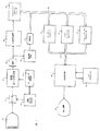
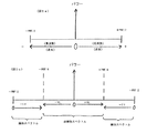
図1は、本発明による超音波診断画像処理装置のブロックダイヤグラムである。図2は、本発明によるエコー集合を取得するための好適な発信波形シーケンスを示す。図3は、図1の集合記憶装置の説明図である。図4aと4bは、図1のウォ−ルフィルタの2つの例を示す。図5aは、従来のドップラースペクトルを説明し、図5bは本発明により作成されたドップラースペクトルを示す。図6は、本発明による異なる高調波スペクトルの分離を示す。図7−10は、本発明により分析され、画像処理される超音波情報の種々のスペクトルを示す。図11−15は、図7−10のスペクトルの種々の超音波情報を描出するためのウォ−ルフィルタ特性を示す。
【0010】
【発明の実施の態様】
最初に図1に、本発明の超音波診断画像処理装置のブロックダイヤグラムを示す。アレー変換器12を有するプローブ10は、体内に超音波エネルギーを発信し、体内組織、細胞、体液、超音波造影剤を使用する場合には造影剤から戻るエコーを受信する。アレー変換器は線形またはカーブドアレーであり、フェーズドアレイまたは線形アレイとして動作する。ドップラー研究には通常、フェーズドアレイ操作が望ましい。アレー変換器による発信と受信のタイミングは、発信ビーム形成器16と受信ビーム形成器18に接続するビーム形成器制御器14により同調される。各ビーム形成器のチャネルはアレー変換器の個々の素子に接続され、個々の素子からの信号の発信と受信を別々に制御する。ビーム形成器制御器の制御下に、ビーム形成器16はアレーの各素子が活性化され波もしくはパルスを発信する時期を決定する。この発信の時間制御は、全アレーにより発信される波が、所定の方向、即ち前もって決められた走査線に沿って操作され、所望の焦点深度に焦点を合わせることを可能にする。2つのビーム形成器のチャネルは、高発信電圧から受信ビーム形成器チャネルの入力を保護する発信/受信スイッチ17により、アレーの素子に接続する。
【0011】
個々の変換器素子によって受信されたエコーは、発信/受信スイッチ17により受信ビーム形成器18の個々のチャネルに転送される。これらの入力経路には、受信エコー信号を増幅するための前置増幅器(preamplifier)や、深さ依存減衰効果を相殺するための時間利得代償回路を含めてもよい。好適例にあるように、受信ビーム形成器18がデジタルビーム形成器であるとき、ビーム形成器の各チャネルにはアナログ−デジタル変換器が前に置かれるかまたは含まれる。ビーム形成器のチャネルは、走査線からの各変換器素子により受信されたエコーを連続的に適切に遅延させ、走査線に沿って共通の点(試料容積(sample volume))から受信された信号を時間一致させる。連続的な遅延変位により、走査線に沿った受信エコー信号の動的焦点合わせが可能となる。次いでチャネルの出力での信号が組合わされ、コヒレントエコー信号のシーケンスが形成され
る。
【0012】
受信ビーム形成器は、動的開口変化の効果を相殺する信号振幅の正規化など、他の処理操作も従来通り実行する。受信ビーム形成器は、複数線受信を実施するために、それぞれがそれ独自のビーム形成器制御器からの遅延プログラミングを有するチャネルの2あるいはそれ以上の群に分割することもできる。複数線受信において、チャネルの各群は、それ自身の走査線に沿って受信ビームを操作し、焦点を合わせ、これによって2あるいはそれ以上の受信走査線を同時に形成する。複数線受信により、より短時間で一画像の全走査線が取得されるので、フレーム速度を上げることができるが、一方、受信走査線の全てが発信開口と一致しているとは限らないので、収差(aberration)効果を生じる傾向が出てくる。
【0013】
走査線に沿って受信されたコヒ−レントエコーのシーケンスを検出することができ、グレースケール値の範囲に調節され、所望の画像記録方式に走査変換され、表示され、このようにしてBモード画像を形成する。図1の装置において、コヒレントエコーは直角位相帯域通過(QBP)フィルタ20により、同相(I)と直角位相(Q)試料に復調される。このI,Q試料はドップラー処理され、ドップラーパワー、速度、加速式、分散、および流れまたは運動の方向を決定し、計算式、(I2+Q2)1 / 2によりエコー信号の振幅の検出に使用することもできる。図1の具体例におけるBモード画像処理では、I,Q試料は処理され、周波数混合回路22によりスペックルを除去される。エコー振幅は、検出器24により検出され、検出されたエコー信号は、エコーデータバス32を通じてグレースケールプロセッサ60に転送され、そこでエコーは対数圧縮され、グレースケールマッピングされる。対数圧縮とグレースケール処理の好適技術の詳細は、アメリカ合衆国特許出願第08/955,819号に見出される。グレースケール信号は、画像データバス82を通じて走査変換器80に転送され、そこでR−θ走査線データは所望の表示形式に変換される。走査変換画像は、表示装置90に表示される。
【0014】
QBPフィルタ20、周波数混合回路22および検出器24の詳細な説明は、アメリカ合衆国特許出願第08/893,426に見出される。
ドップラー画像処理については、走査線はある時間間隔で連続的に走査され、走査線に沿った各試料容積で、時間的にエコーシーケンスが集められる。この時間的エコーシーケンスは、集合(ensemble)と呼ばれ、発信波のシーケンスにより取得され、その繰返し周波数はパルス繰返周波数、PRFと呼ばれる。それぞれの個々に発信された波もしくはパルスは、診断用超音波の通常の無線周波数(r.f.)範囲にあるドップラー周波数と呼ばれる名目上の周波数を示す。PRFは通常、キロヘルツかそれ以下の範囲である。エコー集合は集合記憶装置26に蓄積され、完成された集合がドップラー処理用に作成される。
【0015】
ドップラー処理の従来からの第一段階は、ウォ−ルフィルタ処理である。心臓と血管中の血流の画像処理もしくは測定を実施するとき、血液細胞からの相対的に低いレベルのエコーは、血管や心臓壁などの近接組織により反射された強いエコーに圧倒される場合がある。処理の目的は血流の画像処理もしくは測定であるから、この場合には組織エコーは、除去すべきクラッタとなる。このフィルタの目的が心臓や血管壁からのエコーを除去することにあるので、これらの不要な信号を除去する回路はウォ−ルフィルタと呼ばれている。組織信号は通常血流信号よりも大きい振幅と低い周波数を有するので、これらの信号は振幅、周波数、または両者の組合せによって識別することができる。「フラッシュ(flash)」として知られるドップラー虚像と共に組織信号を除去する好適技術がアメリカ合衆国特許第5,197,477号に開示されている。
【0016】
ウォ−ルフィルタは、血流ドップラー信号を排除し、組織のドップラー信号を通すよう、逆特性で機能させることもできる。組織のこれらの信号がドップラー処理されるとき、心筋や弁膜などの動いている組織の画像が作成される。この画像処理技術は組織ドップラー画像処理として知られている。
【0017】
血流または組織の、フィルタ処理されたドップラー信号は、ドップラープロセッサ40に転送され、そこでそれらはドップラー位相シフトまたは信号強度(パワードップラー)のドップラー計算の実施に使用される。従来よりこれはドップラー信号データのフーリエ変換または自己相関(autocorrelation)により実施される。好適技術は、ドップラー位相シフトとドップラー信号の参照もしくは中心周波数を同時に計算する二次元自己相関の実施である。後者は、位相シフト計算における深さ依存周波数減衰効果の修正に有用である。そのような二次元ドップラープロセッサが、アメリカ合衆国特許5,386,830に記載されている。ドップラー周波数もしくは位相シフトは、エコーを返す血流または組織の速度に比例するので、速度、加速または分散数の延長(production)は、直線的である。色流れドップラーにおいて、血流速度は色スケールにマッピングされ、画像データバス82を通じて走査変換器80に転送され、血流を含む組織構造のグレースケール画像上に重ねられる。パワードップラー画像処理において、ドップラー信号強度は同様にマッピングされ、グレースケール画像上に表示される。アメリカ合衆国特許5,474,073および5,720,291に記載されているように、ドップラーとグレースケール画像データを3Dプロセッサ70で処理し、血流および/または組織の三次元画像表示を形成することもできる。
【0018】
本発明によると、エコー集合は波毎に異なる位相を示す発信波のシーケンスにより取得される。好適例において位相は、図2のパルスシーケンスにより示されるように波毎に180゜位相変化する。説明の容易さのために、画像処理の目的に応じ、より長いパルス周期もしくは単極性パルスを採用することもできるが、これらのパルスはサイン波形の一周期として示される。図中、パルス102が時間T1で発信され、その後走査線からのエコーのシーケンスが取得され、各集合中の第1の試料となる。時間T1からパルス速度(rate)間隔(PRI)と呼ばれる間隔で隔てられている時間T2で、パルス102の反転として示されるパルス104が発信され、パルス 104は、パルス102の有する位相から180゜変化する。同様に、時間T3、T4およびT5におけるパルス106,108および110の位相は、パルス毎に180゜変化する。
【0019】
各パルスの後にエコーが受信され、図3に示すように他の試料が各集合に加えられ、それは集合記憶装置26の目的を説明している。発信パルス102に応答して、走査線に沿った連続試料容積(SV#)から受信されたエコーは、集合記憶装置の第1の列に、T1と記された列に+記号で示されるように記憶される。発信パルス104に応答して、走査線に沿った試料容積から受信されたエコーは、集合記憶装置の第2の列にT2と記された列に−記号で示されたように記憶される。列T3−T5の残りは、パルス106,108および110に応答して受信されるエコーにより満たされる。
【0020】
各試料容積SVの集合は次いで、ウォ−ルフィルタ30中で、ウォールフィルタ処理される。好適例において、ウォ−ルフィルタはマトリックス(matrix)フィルタである。マトリックスウォールフィルタ処理は、適切な積算係数を選択して実施され、該マトリックスフィルタ処理は下式で表わされる。
【0021】
【数1】

ここに、x1・・・・xnは試料の集合であり、 y1・・・・・ynはフィルタ処理された出力値である。エコー値と係数の積ynは、係数により決定された特性に従ってフィルタ処理されたエコー値である。係数は、所望のフィルタ特性、特に所望のフィルタインパルス応答に関するものを考慮して選択される。
【0023】
本発明のさらなる面によると、マトリックスウォ−ルフィルタの組合せ処理は、エコー信号の線形と非線形成分を分離する。以下に論ずるように、この分離は発信信号の位相交替によりドップラー値に導入される位相シフトによりもたらされる。
【0024】
図4aと4bは、ウォ−ルフィルタ30の異なる2つの例を示す。図4aの例は、ウォ−ルフィルタとしての使用に適する有限インパルス応答(FIR)フィルタを示す。集合のエコーは、一連の遅延段階τにシフトされる。集合が遅延段階を通過するとき、試料は、マルチプライヤ120で重み付け係数を積算され、信号に所望のフィルタ特性、およびフィルタ出力信号のシーケンスを作成する加算段階122で加算された結果を与える。図4bは、マルチプライヤ120とアキュムレータ124により形成されたフィルタを示す。この例において、集合のエコーには順次マルチプライヤ120に適用される重み付け係数が積算され、その積はアキュムレータ124に蓄積される。完全な出力値がアキュムレータに蓄積される前に、一連の積算命令が連続して行なわれなければならないので、マルチプライヤ−アキュムレータの例は縦列し、より高速の出力信号を作成することができる。これらのフィルタの例のいずれかの出力は、定期的に跳び越す(skip)ことができ、得られた出力に間引き(decimation)フィルタ特性を与える。集合が有限長さのシーケンスなので、処理を開始するときにフィルタが「振動的に歪む(ring)」ことのないよう、初期化に注意しなければならない。これは直流値を使用するか、または、シーケンスのいくつかの初期値を複製して、エコー値の前に初期化値を加える(pad)ことにより、実施することができる。有限フィルタ長はまた、フィルタ応答がフィルタ処理される集合長によって影響されることを意味し、試料のより長いシーケンスは、より多くの係数、重み付け係数、および積を有し、より複雑で、詳細に調整されたフィルタ特性を与える。
【0025】
従来のドップラー処理により作成されたドップラースペクトルを図5aに示す。ドップラー応答が発信パルスによって効果的にサンプリングされるので、パルス繰返周波数は、エイリアシングなしで検出することができるドップラー周波数の範囲としてナイキスト限界(Nyquist limit; 最大測定可能速度))を設定する。運動または流れは変換器に向かう(+)か、離れる(−)かのいずれかであるから、スペクトルの限界は、−(PRF/2)と+(PRF/2)であり、ゼロの周波数基準に中心がある。縦座標は、ドップラーパワーの大きさである。ドップラーシフト周波数は、運動の速度と直接対応するので、横座標はドップラー周波数と速度の両方に置くことができる。静止物体から戻るドップラー信号は、中央ゼロの速度軸に位置するであろう。動いている血液または組織からの信号のドップラーシフトは、動きの方向により、より遅い速度はより中央軸に近く、より大きい速度は横座標の末端よりに位置付けるように、中央軸の左または右に位置する。
【0026】
本発明の実施により生ずるドップラースペクトルを図5bに示す。従来のスペクトルと同様、図5bのドップラースペクトルは−(PRF/2)と+(PRF/2)のナイキスト限界により境界づけられ、ゼロの速度座標付近に中心がある。しかしながら、パルス毎の発信信号の位相交替は、ドップラーシフトスペクトルを、奇数(線形+より高次の非線形)と偶数(第二高調波+より高次の非線形)成分領域に区分し、静止組織から戻るものなどの静的線形成分の、スペクトルの両端への変位を生じさせる。2次高調波成分が存する非線形領域は、−(PRF/4)と+(PRF/4)により境界づけられ、中心軸付近に中心がある。静止組織から戻る組織高調波成分は、中心軸に見出され、流れている高調波造影剤などの動いている物質から戻る高調波成分は中心軸から外側に、−Vhと+Vhと表示された矢印により示されるように、−(PRF/4)と+(PRF/4)の境界内に見出される。動いていないおよび動いている組織や血液から戻る基本周波数成分など、線形成分が存在する領域は、−(PRF/4)および+(PRF/4)境界から外側に位置する。静止物質からの基本成分は、+Vfおよび−Vfと表示された矢印に示されたように、両末端の内側に位置する速度が増加する物質からの信号成分を有し、スペクトルの−(PRF/2)および+(PRF/2)末端に位置付けられるであろう。従って、適切な領域からの信号成分を選択することによって、使用者は静止目標からの線形信号、静止目標からの非線形信号、動いている目標からの線形信号、または動いている目標からの非線形信号など、所望の分割された信号成分の画像処理または分析を実施することができる。
【0027】
本発明の実施と結果の数学的表現を以下に示す。一連のN個の超音波パルスがT秒のパルス繰返し間隔で発信される。各発信パルスは、前のパルスの反転されたコピーである。
【0028】
【数2】
ここにPk(t)は発信パルスkの圧力波形である。受信エコー、ek(t)は、典型的には変換器通過帯域の中心近く(広帯域発信パルス用)、または発信周波数の2次高調波もしくはその近傍(狭帯域発信パルス用)のいずれかに選択される周波数fcの搬送波(carrier)の直角位相にそれらを混合することにより復調される。復調された信号は次いで処理されドップラースペクトルを作成する。線形分布構造には、連続エコーは下式で表される。
【0030】
【数3】
ここに、Δτd=2Δd/Cs であり、
【0032】
それは、パルス間で変換器に関係する分散構造の軸運動Δdによる時間遅れである(Csは、媒体中の音速)。fcと関連して測定された、連続エコーの間の対応する位相シフトは下式で表される。
【0033】
【数4】
付加されたπ項は、数式2のekの前の負記号の結果である。計算されたドップラー周波数は、従って下式となる。
【0035】
【数5】
ここにvは変換器に関する散乱物体の相対軸速度である。そしてfpr=1/Tは 、 パルス繰返周波数(PRF)である 。従って、線形散乱物体からの信号は、ナイキスト周波数と等しい量だけ移動して、ドップラースペクトル中に現れるであろう。非線形散乱からのエコーは、下式のように、奇数と偶数成分に分解することができる。
【0037】
【数6】
連続PIDエコーにおいて、eodd(t)成分はP(t)と正負符号を交換するが、
eeven(t)成分は交換しない。この分解は、一般的であり、分散過程の正確な性質に依存しない。下式の簡単なモデルにとって、
【0039】
【数7】
eodd(t)は、奇数次の分散項によるエコーを含み、eeven(t)は偶数次の分散項によるエコーを含む。これら2成分によるドップラーシフトは下式となる。
【0041】
【数8】
fd,evenが、従来のドップラーにより作成されるものと同一のドップラーシフトを有することに注意しなければならない。全ての散乱物体速度が、修正(revised)ナイキスト限界に従うとすると、
【0043】
【数9】
それは従来の限界の半分であり、−fpr/4とfpr/4の間のドップラースペクトルの部分は、非線形散乱プロセスから生じる、唯一のドップラー信号を含む(これをここに、スペクトルの低周波数または非線形部分という。)。ドップラースペクトルの残り半分(高周波数または線形部分と呼ぶ。)は、線形散乱と、おそらくより高次の非線形散乱から生じるドップラー信号を含む。
【0045】
図6に示すように本発明による発信波の位相交替により作成された周波数分離は、相補的である。図6aは、2MHzに中心がある名目上(nominal)の発信周波数に応答して受信される2MHzの名目上の周波数付近の基本周波数の帯域、それに続いてそれぞれ約4、6、8および10MHzに中心がある第2、第3、第4および第5次高調波帯域を示す。パルス反転発信と、取得信号の減算の組合せにより実施されるスペクトル分離が、図6bに示される。基本周波数を含む奇数次の高調波は、この処理によって分離される。同様に、加算的組合せによるパルス反転発信は、図6cに示すように、2次高調波を含む偶数次の高調波を分離する。
【0046】
従って、図6bのスペクトルは、図5bで「線形」と標識された領域に存在し、図6cのスペクトルは図5bに「非線形」と標識された領域に存在する。しかしながら、超音波画像処理の変換器は有限の通過帯域を有することを思い起こされなければならない。ワシントン州、ボゼルのエイティーエル・ウルトラサウンド・インコーポレイテッド(ATL Ultrasound Incorporated)によって製造されたP4−2フェーズドアレー変換器により示された通過帯域は、ほぼ図6dの通過帯域130によって示されたものであり、2MHzから4MHzまで実質的に平坦である。従ってP4−2フェーズドアレー変換器は、上記通過帯域130に示された基本と2次高調波帯域を再現し、より高次の帯域は変換器の上部遮断(upper cutoff)により除去される。P4−2変換器によって画像化された非線形および線形スペクトルは従って、高次高調波の大きなエネルギーなしで、基本と2次高調波成分から構成される。これは、P4−2変換器が2MHzの発信波の基本または2次高調波エコーのいずれか単独の画像処理に使用しうることを意味している。
【0047】
図7−10は、本発明による様々な診断用画像処理方法で取得しうる種々のドップラー信号のスペクトルの例を示す。図7aは、低強度波の発信に伴う実質的に静止している組織からのエコーのスペクトルを示す。実質的に全てのスペクトル成分は線形であり、ドップラースペクトルのナイキスト末端の帯域202,204に位置している。発信されたエネルギーの強度が増加すると、図7bのスペクトルが結果として生ずる。同じ静止線形帯域202,204が存在する。しかし、発信エネルギーの増加は、発信波中の高調波成分のより速やかな増強を生じさせ、2次高調波エネルギーは、スペクトルの非線形領域の中央(静止)軸付近に位置する帯域206により示されるように、静止組織から戻るエコー中に含まれる。
【0048】
もし図7bのスペクトル中の2次高調波組織成分だけの画像形成を望むならば、図12のフィルタ通過帯域306に示すものなどの、単純応答特性をフィルタに付与するように、マトリックスフィルタの係数またはFIRフィルタの重みを調整する。このフィルタ通過帯域は、通過帯域の中心の組織高調波成分を通過させるが、通過帯域306の外側の基本成分は通過させないことが分かる。従って、ウォ−ルフィルタはさらなる処理のために使用される信号成分の種類の選択に使用される。
【0049】
図8aは、灌流中の心筋層など、灌流されている組織内の高調波造影剤の低発信強度による検出から得られたスペクトルの内容を示す。造影剤は、帯域212,214に示されたように、発信波の線形成分を、そして非線形帯域216によって示されたように剤の非線形特性による非線形信号成分も反射する。これらの帯域の全ては、ゼロ速度中心およびドップラー帯域の両末端付近に位置し、これは造影剤の組織内の遅い流速から予想される。発信エネルギーが増加し、造影剤の微小気泡を破壊させると、これらの結果のスペクトルは相当に広がり、通常図8bの帯域218に示すように、ドップラースペクトル全体を満たす。帯域218の信号成分をパワードップラー記録方式に効果的に表示することができ、またはアメリカ合衆国特許5,456, 257に記載されたように微分し、振幅検出することができる。
【0050】
図9aは、血管内を流れる造影剤のスペクトルを示す。予想されるように、造影剤のエコーの基本と高調波帯域の両方は、帯域222, 224の位置により示されるように、周波数(速度)Δfだけ静止軸から離れるように動く。ここに、
【0051】
Δf=2vfc/cである(式9参照)。
【0052】
流れている造影剤が、より高い発信エネルギーに曝されると、微小気泡が破裂し、図9bに示すスペクトルを返す。このスペクトルは、微小気泡の破裂により放出された広帯域エネルギーのために広がり、流れる剤の進行速度の基本および2次高調波の戻りに対応する周波数226,228の頂点を有する。
【0053】
図10aは、いかなる造影剤も不存在時に、中程度の発信エネルギーに応答して静止組織から戻るエネルギーのスペクトルを示す。エコーは、帯域232,234に示される基本周波数エネルギーと中程度量の帯域236の組織の高調波エネルギーを戻す。発信エネルギーが実質的に増加すると、図10bの帯域236’に示したように振幅が大きくなるにつれて、発信波の高調波エネルギーは大きい速度で蓄積する。
【0054】
図7−10のスペクトルと帯域は、発信波のサンプリング速度(PRF)が、遭遇する流れまたは運動速度のナイキスト基準を満足していると仮定している。もし高速度域がサンプリング不足になると、生じるスペクトルの高調波は、サンプリング速度基準が満足される領域で部分的に分離されるのみで、サンプリング不足のより高速度域ではスペクトルの他の高調波領域と重なるであろう。
【0055】
図11−15は、ウォ−ルフィルタ用の係数および重みの選択により生じうる多数の通過帯域を示す。図7−10と同様に、図11−15のスペクトル図の横座標は、標識されていないがPRF/4分画で示されている。より複雑な機能は通常、より高次のフィルタとより大きい集合長さを必要とする。図11は、図8のスペクトルである、心筋層内の高調波造影剤の検出に有用なウォ−ルフィルタ通過帯域を示す。低発信エネルギーで、図11aの通過帯域316は、図8aの帯域216からの戻りを極大化するように、非線形領域での中心の低速度利得を極大化するのに使用される。微小気泡の破裂が始まったときに、より穏やかなエネルギーで、低速非線形領域により大きい利得を与えるために、図11bの通過帯域314を使用することができる。より高エネルギーで、図11cの通過帯域318は(スペクトルの末端で)線形成分と、(スペクトルの中心で)静止組織からの高調波成分を拒絶するために使用することができ、一方造影剤の微小気泡の破裂から戻る広帯域の戻りを極大化する。簡単にいうと、スペクトルのある領域に対して他の領域中の信号利得を減少、増加させるために、ドップラースペクトルの異なる領域中のフィルタ利得を利用することができる。
【0056】
図13は、本発明による、高調波造影剤の色流れ画像処理用の詳細設定された通過帯域320を示す。組織高調波からの成分は、スペクトルの中央部では拒絶され、全通過帯域利得がPRF/4境界までの全高調波周波数(速度)範囲について適用される。
【0057】
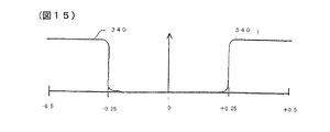
図14と15は、 2次高調波(および、他の偶数次の非線形)および基本(および奇数次の非線形)信号用の理想化された通過帯域を示す。通過帯域330は、PRF/4でのその鋭い遮断により、全ての出所、高調波造影剤、組織高調波からの2次高調波非線形信号を通過させる。図15の相補的通過帯域340は、全ての原因からの線形(基本)信号成分を通過させる。
【0058】
1つの画像または分析処理用のスペクトルの2つの領域を分離するのに、複数のフィルタを使用するいくつかの処理を実施することも予想される。例えばそれぞれが、図9の奇数次高調波(線形)と偶数次高調波帯域を別々に通過させ、そして別々に各組の信号をドップラー処理するために、2つのフィルタを使用することができる。これは、基本信号情報の組織ドップラー処理により、偶数次高調波情報から、拍動している心臓の、動いている心壁内を流れている造影剤の表示を可能にする。第二の例として、(図14に示されたような応答特性を使用して)非線形信号強度を得るために1つのフィルタを使用し、(図15に示された応答特性を使用して)線形信号強度を得るのに他のフィルタを使用し、その両方をパワードップラー処理法により処理することができる。次いで画像平面内の各画素位置での線形信号パワーに対する非線形信号パワーの割合が計算され、表示される。好適例において、この線形と非線形の比は、結果として生じる係数のパワー依存をより小さくするよう、分母の線形値を2乗することにより計算することができる。拡張された係数の組が、別々に蓄積され、次いでドップラー処理される2つの通過帯域について、結果を算出するので、マトリックスウォ−ルフィルタはそのような「2経路」実行によく役立つ。ドップラースペクトルの線形領域を処理するのに使用される係数は、乗法プロセスの間、集合中の1つおきのエコーを反転させる極性を有することができ、奇数次チャネル中のほぼ±(PRF)/2からゼロまでに分布する線形成分を再変調する。
【0059】
本発明者らは、パワードップラーがほとんどの用途に好適ドップラー技術であり、流れの方向でなく、流れの存在が必要な多くの場合に優れた画像を作成することを見出した。潅流中の心臓組織の、潅流している心筋のパワードップラー画像が優れた解像度で作成されている。本発明による色ドップラー画像処理は、例えば、腎臓移植の画像化に非常に有用である。グレースケール表示も可能である。ドップラー集合は通常、2から16の試料の長さに渡りうる一方、より短い集合長さで優れた結果を達成することができることが見出され、2試料集合を有するパワードップラー画像は、高解像度画像を作成し、高い実時間フレーム速度をも与えることが見出された。より長い発信パルスが、ある状況では望ましい。本発明者らは、図1のパワーモ−ションプロセッサ50を使用するパワーモーション画像処理技術により、パルス反転技術により動いている組織から得られた2つの試料を効果的に画像化できることも見出した。パワーモーション画像処理技術とプロセッサ50の詳細が、アメリカ合衆国特許5,718, 229に見出される。
【0060】
受信された集合のエコーからエコーへの分散を導入する他の変調技術を、許容可能な効果をもって使用することができる。例えば、 2つの異なったレベルの間で、連続発信パルスの振幅を交互にし、パルス毎の180゜位相シフトをもって、またはシフトなしで、そして受信エコーが発信パルス振幅に従って正規化され(normalize)、次いで上記したように処理される。振幅変調は、本発明技術の実行に十分な程度の線形と非線形成分の分離を生じさせるのに十分な変位(variation)を生じさせる。もしも180゜位相シフトが使用されないならば、スペクトルの奇数次部分と偶数次部分は逆になる。これが本発明の次善の実行であると判断される一方、それはある環境においては有効であるか、望ましい。
【0061】
本発明は、ドップラースペクトルが図形的にまたは数値的に表示されるPWドップラーの応用に容易に適用することができる。従って、所望のウォ−ルフィルタの選択により、線形または非線形信号成分のドップラースペクトルを、選択的に処理し、表示することができる。
【0062】
線形散乱から非線形散乱を明瞭に分離するので、パルス反転ドップラーは線形組織中の微小気泡造影剤の検出によく適合している。さらに本願技術は、広帯域、高解像度パルスをドップラー用途に使用することを可能にする。
【0063】
本発明は、パルス反転ドップラー超音波診断画像処理に関し、広帯域線形と非線形エコー信号成分を分離しつつ、同時に運動の効果を同時に識別する超音波診断画像処理方法と装置が提供される。本発明方法は、エコーの直線性に依存するようにドップラー領域中のドップラーシフト周波数に、無線周波数(時間)領域中の超音波エコー信号をマッピングする。本発明方法は、これを連続するエコー間の位相シフトを分析することにより実施する。
【0064】
周期的に位相変化する波形の発信シーケンスによりドップラーエコー集合が取得される装置が開示される。エコー集合がドップラー処理中に組合わされると、結果として生ずるドップラースペクトルは、奇数次高調波(例えば線形信号成分)が存在する1つの領域と、偶数次高調波(例えば、2次高調波信号成分)が存在する他の領域というように、別個の領域に分離される。好適例において、ドップラーウォ−ルフィルタは、組織運動、高調波造影剤、組織高調波画像処理情報など、特定種類の処理用信号情報の描出に使用される。
【0065】
本発明の主たる態様を以下に示す。
1、発生する超音波エコーに位相差を生じさせるよう、体内に変調された超音波シーケンスを発信する段階、該発信シーケンスに応答した超音波エコー信号の集合を受信する段階、そして、線形と非線形信号成分の位相シフト情報を分離するために該集合を分析する段階、以上の段階からなる線形と非線形超音波エコー信号成分の微分的位相変調方法。2、該発信する段階が、パルス毎に変調された超音波の発信からなる前記1の方法。3、該パルス毎に変調された超音波の発信が、線形と非線形信号成分の間に位相の分離を生じさせる前記2の方法。4、該変調が、該発信パルス速度のナイキスト限界(最大測定可能速度)で生じる前記2の方法。5、該変調が、パルス毎の180゜位相変化、パルス毎の振幅変調、またはパルス毎の位相と振幅変調の組合せである前記2の方法。6、該分析する段階が、線形と非線形の信号成分を微分的に検出する段階からなる前記1の方法。7、微分的に検出する段階が、該集合をパワードップラー処理することからなる前記6の方法。8、微分的に検出する段階が、該集合を色流れ処理することからなる前記6の方法。
【0066】
9、位相変化超音波のシーケンスを発信する段階、該位相変化超音波に応答した超音波エコー信号の集合を受信する段階、そして、エコー信号の該集合をドップラー処理し、エコー信号の直線性に従って分離されたドップラー位相シフト情報を作成する段階、以上の段階からなる、線形と非線形信号情報を分離するようにドップラー領域に、無線周波数超音波エコー信号情報をマッピングする方法。10、一つの波から次へと異なって振幅変調された超音波シーケンスを体内に発信する段階、該振幅変調超音波に応答した超音波エコー信号の集合を受信する段階、そして、エコーの該集合の位相シフト特性を基準に、受信超音波エコー信号を処理し、分離された線形と非線形信号成分を作成する段階、以上の段階からなる、線形と非線形の超音波信号成分を分離する方法。11、被検者の体内に超音波の変調シーケンスを発信する超音波発信器、超音波の該変調発信シーケンスに応答した超音波エコー信号の集合を受信する受信器、および、該エコーの位相シフト情報を線形と非線形信号成分に分離するプロセッサ、からなる、線形と非線形超音波エコー信号成分を識別する超音波診断画像処理装置。12、該発信器が、パルス毎に変調された超音波を発信する11の超音波診断画像処理装置。13、該発信パルス毎の変調が、線形と非線形信号成分の間に位相分離を導入することからなる前記12の超音波診断画像処理装置。14、該変調が、該発信パルス速度(rate)のナイキスト限界で生じる前記12の超音波診断画像処理装置。15、該変調が、パルス毎の180゜位相変化、パルス毎の振幅変調、またはパルス毎の位相と振幅変調の組合せからなる前記12の超音波診断画像処理装置。16、該プロセッサが、線形と非線形信号成分を微分的に検出する微分プロセッサからなる前記11の超音波診断画像処理装置。17、該プロセッサが、パワードップラープロセッサからなる前記16の超音波診断画像処理装置。18、該プロセッサが、色流れプロセッサからなる前記16の超音波診断画像処理装置。
【0067】
19、被検者の体内に位相変化超音波のシーケンスを発信する超音波発信器、該位相変化超音波に応答した超音波エコー信号の集合を受信する受信器、および、エコー信号の該集合を処理し、該超音波エコー信号の直線性に従って描出されたドップラー位相シフト情報を作成するドップラープロセッサ、からなる線形と非線形の超音波信号情報を分離する超音波診断画像処理装置。20、被検者の体内に位相変化超音波のシーケンスを発信する発信器、該超音波に応答するしたエコーの集合を受信する受信器、および該集合を処理し、動いている組織の奇数次または偶数次高調波信号の効果のスペクトルを識別する組織ドップラープロセッサ、からなる動いている組織の高調波信号効果を識別する超音波診断画像処理装置。21、被検者の体内に位相変化超音波のシーケンスを発信する発信器、該超音波に応答したエコーの集合を受信する受信器、および該集合を処理し、動いている組織または高調波造影剤の奇数次または偶数次高調波信号効果のスペクトルを識別するパワードップラープロセッサ、からなる動いている組織または高調波造影剤の高調波信号効果を識別する超音波診断画像処理装置。22、被検者の体内に位相変化超音波のシーケンスを発信する超音波発信器、該位相変化超音波に応答した超音波エコー信号の集合を受信する受信器、およびエコー信号の該集合を処理し、ドップラー位相シフト情報を作成するドップラープロセッサ、および、奇数次高調波ドップラー位相シフト情報と偶数次高調波ドップラー位相シフト情報を、それぞれ通過させる第1と第2フィルタ、からなる奇数次と偶数次高調波の超音波信号情報を分離する超音波診断画像処理装置。23、さらに、奇数次と偶数次高調波位相シフト情報の比を計算するための該第1と第2のフィルタに接続する比回路からなる前記22の超音波診断画像処理装置。
【0068】
【発明の効果】
運動の効果を識別しつつ、同時に広帯域の線形および非線形エコー信号成分を分離する超音波診断画像処理方法および装置が提供される。該方法は、超音波エコーの直線性により、無線周波数領域の超音波エコー信号を、ドップラー領域のドップラーシフト周波数にマッピングする。変調発信シーケンスに応答して受信された連続エコー間の位相シフトを分析することによりこれを実施する。周期的に位相変化する波形のシーケンスの1つの発信により1つのドップラーエコー集合が取得される。エコーの集合が組合わされたドップラースペクトルは、奇数次高調波(例えば線形信号成分)が存在する1つの領域と、偶数次高調波(例えば第二高調波信号成分)が存在するその他の領域という、別々の領域に分けられる。各領域は、運動していない体内の静止物質からの線形と非線形エコー中に含まれる画像化される物質の運動に対応する周波数範囲を含んでいる。好適例においては、組織の運動、高調波造影剤、組織高調波画像処理情報などの、特定種類の処理用信号情報を同時に描出するのにドップラーフィルタが使用される。
【図面の簡単な説明】
【図1】 本発明超音波診断画像処理装置のブロックダイヤグラムである。
【図2】 エコー集合を取得するための好適発信波形シーケンスを示す。
【図3】 図1の集合記憶装置の説明図である。
【図4】 図1のウォ−ルフィルタの2つの相互の例を示す。
【図5】 従来の及び本発明のドップラースペクトルを示す。
【図6】 本発明による異なる高調波スペクトルの分離を示す。
【図7】 分析、画像処理される超音波情報スペクトルの第1の例である。
【図8】 分析、画像処理される超音波情報スペクトルの第2の例である。
【図9】 分析、画像処理される超音波情報スペクトルの第3の例である。
【図10】 分析、画像処理される超音波情報スペクトルの第4の例である。
【図11】 超音波情報の描出におけるウォ−ルフィルタ特性の第1の例である。
【図12】 超音波情報の描出におけるウォ−ルフィルタ特性の第2の例である。
【図13】 超音波情報の描出におけるウォ−ルフィルタ特性の第3の例である。
【図14】 超音波情報の描出におけるウォ−ルフィルタ特性の第4の例である。
【図15】 超音波情報の描出におけるウォ−ルフィルタ特性の第5の例である。
【符号の説明】
10・・・プローブ、12・・・アレー変換器、14・・・ビーム形成器制御器、16・・・発信ビーム形成器、17・・・発信/受信スイッチ、18・・・受信ビーム形成器、20・・・QBPフィルタ、22・・・周波数混合回路、24・・・検出器、30・・・ウォールフィルタ、32・・・エコーデータバス、50・・・パワーモーションプロセッサ、60・・・グレースケールプロセッサ、70・・・3Dプロセッサ、80・・・走査変換器、82・・・画像データバス、90・・・表示装置、120・・・マルチプライヤ、124・・・アキュムレータ。[0001]
BACKGROUND OF THE INVENTION
The present invention relates to methods and apparatus for ultrasonic diagnostic image processing, and more particularly to detection and processing of echoes from linear and nonlinear ultrasonic scatterers with the new technique of pulse-reversal Doppler.
[0002]
[Prior art]
In recent years, two new diagnostic ultrasound image processing technologies have emerged that utilize nonlinear signals instead of conventional linear signals. In conventional ultrasonic image processing, an echo reflected from a transmitted wave is received and detected to form an image. These echoes differ only in the amplitude attenuation caused by the absorption of acoustic energy, but are called linear echoes because they represent the transmitted waveform at virtually every point including frequency and waveform. Corresponding to the echo amplitude reduction means that the echo is related to the transmitted waveform in a linear function, and is therefore called the term linear image processing.
[0003]
Received echoes may also contain non-linear signal components from several sources. These components have a non-linear relationship with respect to the transmitted waveform. One source of non-linear effects is the strain experienced by the transmitted waveform as it passes through the tissue. As sound waves travel through the tissue, the speed of the compressional phase of the wave exceeds the speed of the rarefactional phase. The difference in the two-phase velocities of the transmitted wave causes waveform distortion step by step as it travels through the tissue, resulting in harmonic components of the original wave frequency. When these distorted waveforms reflect, the returning echo contains these distortions, and the received echo contains the fundamental frequency and higher order harmonic energy of the fundamental frequency. Detection and image processing of harmonics of these naturally occurring transmission waveforms are called tissue harmonic image processing.
[0004]
The second source of the nonlinear echo component is a microbubble contrast agent. Today's new generation of contrast agents, when insonified with sufficient energy levels, resonate irregularly and nonlinearly, thus causing a nonlinear acoustic energy response. This non-linear energy as well as the fundamental frequency energy is returned to the transducer where it is received, processed and displayed. When the microbubbles are irradiated with a higher energy level, the microbubbles are destroyed by the irradiated sound wave, and a strong echo that clearly changes from pulse to pulse can be created and easily detected and displayed. In any case, these strong nonlinear microbubble responses can be used to form very clear images of body fluids containing microbubbles.
[0005]
[Problems to be solved by the invention]
Conventional methods for separating linear and non-linear signals are based on frequencies using filters. Received echoes containing fundamental and harmonic signals can be low pass or band pass filtered to pass the fundamental frequency signal and eliminate the second harmonic signal. The signal can also be high pass or higher frequency band pass filtered to pass the second harmonic signal out of the fundamental frequency. However, filter separation of fundamental and harmonic energy is band limited by the passband of the bandpass filter used, and is not fully effective if there is a frequency overlap between the fundamental and harmonic energy.
[0006]
A greatly improved fundamental and harmonic signal separation technique that avoids the need for filters and their limitations is described in US Pat. No. 5,706,819. This patent, one of the present inventors, discloses a technique called “pulse inversion” that separates the fundamental and harmonic signal components by signal processing. In the pulse inversion method, two opposite phase waveforms are transmitted and an echo is received after each transmission. The two echo sequences are then added or subtracted on a spatial basis. When echoes received at a certain position are added, linear components that are in a linear relationship with the transmitted waveform and differ only in phase are canceled because their phases are opposite. Most of the nonlinear echo components from the continuous pulse are additively combined, not in antiphase. Correspondingly, when two echoes from a position are subtracted, the opposite phase fundamental (or linear) components are augmented with each other, while the majority of the non-linear components are eliminated by subtraction.
[0007]
Since pulse inversion separation does not depend on a filter, it is effective for separation of wideband signals even when the fundamental and harmonic component frequencies overlap. However, since the pulse inversion is a two-pulse system, it tends to be a target of a moving virtual image. In particular, since the response is generated in any case, the nonlinear echo and the motion cannot be distinguished by the pulse inversion method. Therefore, it is desirable to be able to detect and separate the Doppler shift of the linear and nonlinear components of the echo. Further, it is desirable that the linear and nonlinear signal components can be sufficiently separated, and it is desirable that the nonlinear echo component can be distinguished from the effect of motion. Such signal separation is desirably wideband operation and not hampered by the limitations of the rf (radio frequency) filter circuit.
[0008]
[Means for Solving the Problems]
The present invention provides an ultrasonic diagnostic image processing method and apparatus that identifies motion effects while simultaneously separating broadband linear and nonlinear echo signal components. In the method of the present invention, the ultrasonic echo signal in the radio frequency (time) domain is mapped to the Doppler shift frequency in the Doppler domain according to the linearity of the echo. In the method of the invention, this is done by analyzing the phase shift between successive echoes received in response to a modulated transmission sequence. According to the method of the present invention, one Doppler echo set is acquired by one transmission of a waveform sequence whose phase changes periodically. When a set of echoes is combined during Doppler processing, the resulting Doppler spectrum is an odd harmonic (eg, a linear signal component) present in one region and an even harmonic (ex. Linear signal component) present in the other region ( For example, the second harmonic signal component) is divided into separate regions. Each region spans a frequency range corresponding to the motion of the material being imaged contained in linear and nonlinear echoes from stationary material in the body without the presence of motion. In a preferred embodiment, Doppler filters are used to simultaneously depict specific types of processing signal information, such as tissue motion, harmonic contrast agents, or tissue harmonic image processing information. An apparatus for carrying out the method of the present invention will also be described.
[0009]
FIG. 1 is a block diagram of an ultrasonic diagnostic image processing apparatus according to the present invention. FIG. 2 shows a preferred outgoing waveform sequence for obtaining an echo set according to the present invention. FIG. 3 is an explanatory diagram of the collective storage device of FIG. 4a and 4b show two examples of the wall filter of FIG. FIG. 5a illustrates a conventional Doppler spectrum, and FIG. 5b shows a Doppler spectrum created according to the present invention. FIG. 6 illustrates the separation of different harmonic spectra according to the present invention. 7-10 show various spectra of ultrasound information analyzed and imaged according to the present invention. FIG. 11-15 shows the wall filter characteristics for rendering various ultrasonic information of the spectrum of FIG. 7-10.
[0010]
BEST MODE FOR CARRYING OUT THE INVENTION
First, FIG. 1 shows a block diagram of the ultrasonic diagnostic image processing apparatus of the present invention. The
[0011]
Echoes received by the individual transducer elements are forwarded by the transmit / receive
The
[0012]
The receive beamformer also performs other processing operations conventionally, such as signal amplitude normalization that offsets the effects of dynamic aperture changes. The receive beamformer can also be divided into two or more groups of channels, each with delay programming from its own beamformer controller, to perform multi-line reception. In multi-line reception, each group of channels manipulates and focuses the receive beam along its own scan line, thereby forming two or more receive scan lines simultaneously. Multi-line reception allows all scanning lines of one image to be acquired in a shorter time, so the frame speed can be increased. However, not all reception scanning lines coincide with the transmission aperture. There is a tendency to produce an aberration effect.
[0013]
The sequence of coherent echoes received along the scan line can be detected, adjusted to a range of gray scale values, scan converted to the desired image recording scheme and displayed, thus B-mode image Form. In the apparatus of FIG. 1, the coherent echo is demodulated by the quadrature bandpass (QBP) filter 20 into in-phase (I) and quadrature (Q) samples. The I and Q samples are Doppler processed to determine Doppler power, velocity, acceleration, dispersion, and direction of flow or motion, and a formula (I2+ Q2)1 / 2Thus, it can also be used to detect the amplitude of the echo signal. In the B-mode image processing in the specific example of FIG. 1, the I and Q samples are processed and speckles are removed by the
[0014]
A detailed description of
For Doppler image processing, the scan line is continuously scanned at certain time intervals, and echo sequences are collected in time for each sample volume along the scan line. This temporal echo sequence is called an ensemble and is acquired by a sequence of outgoing waves, and its repetition frequency is called a pulse repetition frequency, PRF. Each individually transmitted wave or pulse exhibits a nominal frequency called the Doppler frequency that is in the normal radio frequency (r.f.) range of diagnostic ultrasound. The PRF is usually in the range of kilohertz or less. The echo set is stored in the
[0015]
The conventional first stage of Doppler processing is wall filter processing. When imaging or measuring blood flow in the heart and blood vessels, relatively low level echoes from blood cells can be overwhelmed by strong echoes reflected by nearby tissues such as blood vessels and heart walls. is there. Since the purpose of the processing is image processing or measurement of blood flow, in this case, the tissue echo is a clutter to be removed. Since the purpose of this filter is to remove echoes from the heart and blood vessel walls, a circuit for removing these unnecessary signals is called a wall filter. Since tissue signals usually have larger amplitudes and lower frequencies than blood flow signals, these signals can be distinguished by amplitude, frequency, or a combination of both. A suitable technique for removing tissue signals along with a Doppler virtual image known as "flash" is disclosed in US Pat. No. 5,197,477.
[0016]
The wall filter can also function with inverse characteristics to eliminate the blood flow Doppler signal and pass the tissue Doppler signal. When these tissue signals are Doppler processed, images of moving tissue such as the myocardium and valvular membrane are created. This image processing technique is known as tissue Doppler image processing.
[0017]
The filtered blood flow or tissue Doppler signals are forwarded to a
[0018]
According to the present invention, the echo set is acquired by a sequence of transmitted waves showing different phases for each wave. In the preferred embodiment, the phase changes 180 ° from wave to wave as shown by the pulse sequence of FIG. For ease of explanation, longer pulse periods or unipolar pulses may be employed depending on the purpose of image processing, but these pulses are shown as one period of a sine waveform. In the figure, a
[0019]
An echo is received after each pulse and another sample is added to each set as shown in FIG. 3, which explains the purpose of the
[0020]
Each set of sample volumes SV is then wall filtered in the
[0021]
[Expression 1]
Where x1... xnIs a set of samples y1... ynIs the filtered output value. Echo value and coefficient product ynIs the echo value filtered according to the characteristics determined by the coefficients. The coefficients are selected taking into account the desired filter characteristics, particularly those relating to the desired filter impulse response.
[0023]
According to a further aspect of the invention, the combined processing of the matrix wall filter separates the linear and non-linear components of the echo signal. As discussed below, this separation is caused by a phase shift introduced into the Doppler value by phase shift of the transmitted signal.
[0024]
FIGS. 4 a and 4 b show two different examples of the
[0025]
A Doppler spectrum created by conventional Doppler processing is shown in FIG. 5a. Since the Doppler response is effectively sampled by the transmitted pulse, the pulse repetition frequency sets the Nyquist limit (Nyquist limit) as the range of Doppler frequencies that can be detected without aliasing. Since motion or flow is either towards the transducer (+) or away (-), the spectral limits are-(PRF / 2) and + (PRF / 2), a zero frequency reference There is a center. The ordinate is the magnitude of Doppler power. Since the Doppler shift frequency directly corresponds to the speed of motion, the abscissa can be placed on both the Doppler frequency and speed. The Doppler signal returning from the stationary object will be located on the central zero velocity axis. The Doppler shift of the signal from moving blood or tissue is to the left or right of the central axis, depending on the direction of movement, so that slower velocities are closer to the central axis and larger velocities are located closer to the end of the abscissa. To position.
[0026]
The Doppler spectrum produced by the practice of the present invention is shown in FIG. Like the conventional spectrum, the Doppler spectrum of FIG. 5b is bounded by the Nyquist limit of-(PRF / 2) and + (PRF / 2) and is centered near the zero velocity coordinate. However, the phase shift of the transmitted signal for each pulse is performed by dividing the Doppler shift spectrum into odd (linear + higher order non-linear) and even (second harmonic + higher order non-linear) component regions, and from stationary tissue. It causes displacement of static linear components, such as those returning, to the ends of the spectrum. The nonlinear region where the second harmonic component exists is bounded by-(PRF / 4) and + (PRF / 4), and has a center near the central axis. Tissue harmonic components returning from stationary tissue are found in the central axis, and harmonic components returning from moving material such as flowing harmonic contrast agents are outward from the central axis, −VhAnd + VhIs found within the boundary of-(PRF / 4) and + (PRF / 4), as indicated by the arrow labeled. Regions with linear components, such as non-moving and moving tissue and fundamental frequency components returning from blood, are located outward from the-(PRF / 4) and + (PRF / 4) boundaries. Basic component from stationary material is + VfAnd -VfAs shown by the arrows labeled, it has signal components from a material with increasing velocity located inside both ends and is located at the-(PRF / 2) and + (PRF / 2) ends of the spectrum Will be done. Thus, by selecting the signal components from the appropriate region, the user can obtain a linear signal from a stationary target, a nonlinear signal from a stationary target, a linear signal from a moving target, or a nonlinear signal from a moving target. Etc., image processing or analysis of the desired divided signal components can be performed.
[0027]
A mathematical representation of the practice and results of the invention is shown below. A series of N ultrasonic pulses is transmitted at a pulse repetition interval of T seconds. Each outgoing pulse is an inverted copy of the previous pulse.
[0028]
[Expression 2]
P herek(t) is a pressure waveform of the transmission pulse k. Receive echo, ek(t) is typically a frequency f selected either near the center of the transducer passband (for broadband transmit pulses) or at or near the second harmonic of the transmit frequency (for narrowband transmit pulses).cAre demodulated by mixing them into quadratures of a plurality of carriers. The demodulated signal is then processed to create a Doppler spectrum. In the linear distribution structure, the continuous echo is expressed by the following equation.
[0030]
[Equation 3]
Where Δτd= 2Δd / CsAnd
[0032]
It is the time delay due to the axial motion Δd of the dispersive structure related to the transducer between pulses (CsIs the speed of sound in the medium). fcThe corresponding phase shift between successive echoes measured in relation to is expressed as:
[0033]
[Expression 4]
The added π term is e in
[0035]
[Equation 5]
Where v is the relative axial velocity of the scattering object with respect to the transducer. And fpr= 1 / T is the pulse repetition frequency (PRF). Thus, the signal from the linear scattering object will move by an amount equal to the Nyquist frequency and appear in the Doppler spectrum. Echoes from non-linear scattering can be broken down into odd and even components as
[0037]
[Formula 6]
In continuous PID echo, eoddThe (t) component exchanges the sign of P (t) with the sign,
eevenThe component (t) is not exchanged. This decomposition is general and does not depend on the exact nature of the dispersion process. For a simple model of the following formula,
[0039]
[Expression 7]
eodd(t) contains the echo due to the odd-order dispersion term, eeven(t) includes echoes with even-order dispersion terms. The Doppler shift by these two components becomes the following formula.
[0041]
[Equation 8]
fd, evenNote that has the same Doppler shift as that produced by conventional Doppler. If all scattering object velocities obey the revised Nyquist limit,
[0043]
[Equation 9]
That is half of the traditional limit, and −fpr/ 4 and fprThe portion of the Doppler spectrum between / 4 contains the only Doppler signal resulting from the nonlinear scattering process (this is referred to herein as the low frequency or nonlinear portion of the spectrum). The other half of the Doppler spectrum (referred to as the high frequency or linear portion) contains linear scattering and possibly Doppler signals resulting from higher order nonlinear scattering.
[0045]
As shown in FIG. 6, the frequency separation created by the phase shift of the transmitted wave according to the present invention is complementary. FIG. 6a shows a band of fundamental frequencies near a nominal frequency of 2 MHz received in response to a nominal transmission frequency centered at 2 MHz, followed by approximately 4, 6, 8 and 10 MHz, respectively. The second, third, fourth and fifth harmonic bands with a center are shown. The spectral separation performed by the combination of pulse inversion transmission and acquisition signal subtraction is shown in FIG. 6b. Odd-order harmonics including the fundamental frequency are separated by this process. Similarly, pulse reversal transmission by additive combination separates even-order harmonics including second-order harmonics, as shown in FIG. 6c.
[0046]
Thus, the spectrum of FIG. 6b is in the region labeled “linear” in FIG. 5b, and the spectrum of FIG. 6c is in the region labeled “non-linear” in FIG. 5b. However, it must be recalled that the transducer for ultrasonic image processing has a finite passband. The passband shown by the P4-2 phased array transducer manufactured by ATL Ultrasound Incorporated in Bozelle, Washington is approximately that shown by
[0047]
7-10 show examples of spectra of various Doppler signals that can be obtained by various diagnostic image processing methods according to the present invention. FIG. 7a shows the spectrum of echoes from substantially stationary tissue with the transmission of low intensity waves. Substantially all spectral components are linear and are located in
[0048]
If it is desired to image only the second harmonic tissue components in the spectrum of FIG. 7b, the coefficients of the matrix filter to give the filter a simple response characteristic, such as that shown in the
[0049]
FIG. 8a shows the spectral content obtained from the detection of harmonic contrast agents in the perfused tissue, such as the myocardium during perfusion, with low transmission intensity. The contrast agent reflects the linear component of the transmitted wave as shown in
[0050]
FIG. 9a shows the spectrum of the contrast agent flowing in the blood vessel. As expected, both the fundamental and harmonic bands of the contrast agent echo move away from the stationary axis by a frequency (velocity) Δf, as indicated by the location of the
[0051]
Δf = 2vfc/ C (see Equation 9).
[0052]
When the flowing contrast agent is exposed to higher transmitted energy, the microbubbles burst and return the spectrum shown in FIG. 9b. This spectrum is broadened due to the broadband energy released by the bursting of the microbubbles and has peaks at
[0053]
FIG. 10a shows the spectrum of energy returning from stationary tissue in response to moderate transmitted energy in the absence of any contrast agent. The echo returns the fundamental frequency energy shown in
[0054]
The spectrum and bands in FIGS. 7-10 assume that the outgoing sampling rate (PRF) satisfies the Nyquist criterion for the flow or motion velocity encountered. If the high speed region is undersampled, the resulting spectral harmonics will only be partially separated in the region where the sampling rate criterion is satisfied, while other higher harmonic regions of the spectrum in the undersampled higher speed region. Will overlap.
[0055]
FIGS. 11-15 illustrate a number of passbands that can result from the selection of coefficients and weights for the wall filter. Similar to FIGS. 7-10, the abscissas of the spectrum diagrams of FIGS. 11-15 are not labeled but are shown in the PRF / 4 fraction. More complex functions usually require higher order filters and a larger set length. FIG. 11 shows the wall filter passband useful for detecting harmonic contrast agents in the myocardium, which is the spectrum of FIG. At low transmit energy, the
[0056]
FIG. 13 shows a
[0057]
FIGS. 14 and 15 show idealized passbands for second harmonic (and other even order nonlinear) and fundamental (and odd order nonlinear) signals.
[0058]
It is also envisaged to perform several processes that use multiple filters to separate two regions of the spectrum for one image or analysis process. For example, two filters can be used to each separately pass the odd harmonic (linear) and even harmonic bands of FIG. 9 and doppler each set of signals separately. This enables the display of contrast agents flowing in the moving heart wall of the beating heart from even harmonic information by tissue Doppler processing of the basic signal information. As a second example, one filter is used to obtain nonlinear signal strength (using the response characteristic as shown in FIG. 14) and (using the response characteristic shown in FIG. 15). Other filters can be used to obtain linear signal strength, both of which can be processed by the power Doppler processing method. The ratio of nonlinear signal power to linear signal power at each pixel position in the image plane is then calculated and displayed. In the preferred embodiment, this linear to non-linear ratio can be calculated by squaring the linear value of the denominator to make the resulting coefficient less power dependent. The matrix wall filter is useful for such a “two-pass” implementation because the expanded set of coefficients is calculated separately for two passbands that are accumulated separately and then Doppler processed. The coefficients used to process the linear region of the Doppler spectrum can have a polarity that inverts every other echo in the set during the multiplicative process, approximately ± (PRF) / Remodulate linear components distributed from 2 to zero.
[0059]
The inventors have found that power Doppler is the preferred Doppler technology for most applications and produces superior images in many cases where the presence of flow is required, not the direction of flow. A power Doppler image of the perfused myocardium of the perfused heart tissue has been created with excellent resolution. Color Doppler image processing according to the present invention is very useful, for example, for imaging kidney transplants. Grayscale display is also possible. While Doppler sets can typically range from 2 to 16 sample lengths, it has been found that excellent results can be achieved with shorter set lengths, and power Doppler images with 2 sample sets are high resolution. It has been found to create images and also give high real-time frame rates. Longer transmission pulses are desirable in some situations. The inventors have also found that the power motion image processing technique using the
[0060]
Other modulation techniques that introduce dispersion from echo to echo of the received set can be used with an acceptable effect. For example, between two different levels, alternating the amplitude of a continuous transmitted pulse, with or without a 180 ° phase shift per pulse, and the received echo is normalized according to the transmitted pulse amplitude, then Processed as described above. Amplitude modulation produces enough variation to cause a separation of linear and nonlinear components sufficient to implement the technique of the present invention. If a 180 ° phase shift is not used, the odd and even order parts of the spectrum are reversed. While this is judged to be a sub-optimal implementation of the present invention, it is effective or desirable in some circumstances.
[0061]
The present invention can be easily applied to PW Doppler applications in which the Doppler spectrum is displayed graphically or numerically. Therefore, depending on the selection of the desired wall filter, the Doppler spectrum of the linear or nonlinear signal component can be selectively processed and displayed.
[0062]
Because it clearly separates non-linear scatter from linear scatter, pulse inversion Doppler is well suited for the detection of microbubble contrast agents in linear tissue. In addition, the present technology allows broadband, high resolution pulses to be used for Doppler applications.
[0063]
The present invention relates to pulse-reversed Doppler ultrasonic diagnostic image processing, and provides an ultrasonic diagnostic image processing method and apparatus that simultaneously separates broadband linear and nonlinear echo signal components and simultaneously identifies the effects of motion. The method of the present invention maps the ultrasound echo signal in the radio frequency (time) domain to the Doppler shift frequency in the Doppler domain, depending on the linearity of the echo. The method of the present invention does this by analyzing the phase shift between successive echoes.
[0064]
An apparatus is disclosed in which a Doppler echo set is acquired by a transmission sequence of a waveform that periodically changes phase. When echo sets are combined during Doppler processing, the resulting Doppler spectrum consists of one region where there are odd harmonics (eg, linear signal components) and even harmonics (eg, second harmonic signal components). ) Are separated into separate areas, such as other areas. In a preferred embodiment, the Doppler wall filter is used for rendering specific types of processing signal information, such as tissue motion, harmonic contrast agents, tissue harmonic image processing information.
[0065]
The main aspects of the present invention are shown below.
1. transmitting a modulated ultrasound sequence in the body so as to cause a phase difference in the generated ultrasound echo, receiving a set of ultrasound echo signals in response to the transmitted sequence, and linear and nonlinear A method of analyzing the set to separate phase shift information of signal components, a differential phase modulation method of linear and nonlinear ultrasonic echo signal components comprising the above steps. 2. The method according to 1 above, wherein the transmitting step includes transmitting ultrasonic waves modulated for each pulse. 3. The method of 2 above, wherein transmission of ultrasonic waves modulated for each pulse causes phase separation between linear and nonlinear signal components. 4. The method of 2 above, wherein the modulation occurs at the Nyquist limit (maximum measurable speed) of the transmission pulse speed. 5. The method according to 2 above, wherein the modulation is a 180 ° phase change per pulse, an amplitude modulation per pulse, or a combination of phase and amplitude modulation per pulse. 6. The method of
[0066]
9. transmitting a sequence of phase-change ultrasound, receiving a set of ultrasonic echo signals in response to the phase-change ultrasound, and Dopplering the set of echo signals according to the linearity of the echo signal A method of mapping radio frequency ultrasonic echo signal information to a Doppler region so as to separate linear and nonlinear signal information, comprising the steps of creating separated Doppler phase shift information and the above steps. 10. Transmitting an amplitude-modulated ultrasound sequence differently from one wave to the next, receiving a set of ultrasound echo signals in response to the amplitude-modulated ultrasound, and the set of echoes A method of processing a received ultrasonic echo signal on the basis of the phase shift characteristic of the above and creating separated linear and nonlinear signal components, and a method of separating linear and nonlinear ultrasonic signal components, comprising the above steps. 11. An ultrasonic transmitter that transmits an ultrasonic modulation sequence into the body of a subject, a receiver that receives a set of ultrasonic echo signals in response to the ultrasonic modulation sequence, and a phase shift of the echo An ultrasonic diagnostic image processing apparatus for identifying linear and nonlinear ultrasonic echo signal components, comprising a processor for separating information into linear and nonlinear signal components. 12. An ultrasonic diagnostic image processing apparatus according to 11, wherein the transmitter transmits an ultrasonic wave modulated for each pulse. 13. The ultrasonic diagnostic image processing apparatus according to 12, wherein the modulation for each transmission pulse includes phase separation between linear and nonlinear signal components. 14. The ultrasonic diagnostic image processing apparatus according to 12, wherein the modulation occurs at a Nyquist limit of the transmission pulse rate. 15. The ultrasonic diagnostic image processing apparatus according to 12, wherein the modulation comprises a 180 ° phase change for each pulse, an amplitude modulation for each pulse, or a combination of phase and amplitude modulation for each pulse. 16. The ultrasonic diagnostic image processing apparatus according to 11, wherein the processor comprises a differential processor that differentially detects linear and nonlinear signal components. 17. The sixteen ultrasonic diagnostic image processing apparatus, wherein the processor is a power Doppler processor. 18. The 16 ultrasonic diagnostic image processing apparatus, wherein the processor is a color flow processor.
[0067]
19. An ultrasonic transmitter that transmits a sequence of phase change ultrasonic waves into the body of a subject, a receiver that receives a set of ultrasonic echo signals in response to the phase change ultrasonic waves, and the set of echo signals. An ultrasonic diagnostic image processing apparatus that separates linear and nonlinear ultrasonic signal information, comprising: a Doppler processor that processes and creates Doppler phase shift information drawn according to the linearity of the ultrasonic echo signal. 20, a transmitter for transmitting a sequence of phase change ultrasound into the body of a subject, a receiver for receiving a set of echoes in response to the ultrasound, and an odd order of tissue that is processing and moving the set An ultrasonic diagnostic image processing apparatus for identifying harmonic signal effects of moving tissue, comprising: a tissue Doppler processor that identifies a spectrum of effects of even harmonic signals. 21. A transmitter that transmits a sequence of phase-change ultrasound into the body of a subject, a receiver that receives a set of echoes in response to the ultrasound, and a tissue or harmonic imaging that processes the set and is moving An ultrasonic diagnostic image processing device for identifying harmonic signal effects of moving tissue or harmonic contrast agents comprising a power Doppler processor for identifying a spectrum of odd-order or even-order harmonic signal effects of the agent. 22. An ultrasonic transmitter that transmits a phase-change ultrasonic sequence into the body of a subject, a receiver that receives a set of ultrasonic echo signals in response to the phase-change ultrasonic wave, and processes the set of echo signals An odd-order and even-order comprising first and second filters that pass Doppler phase-shift information and odd-order harmonic Doppler phase-shift information and even-order harmonic Doppler phase-shift information, respectively. An ultrasonic diagnostic image processing apparatus that separates ultrasonic signal information of harmonics. 23. The ultrasonic diagnostic image processing apparatus according to 22, further comprising a ratio circuit connected to the first and second filters for calculating a ratio of odd-order and even-order harmonic phase shift information.
[0068]
【The invention's effect】
An ultrasound diagnostic image processing method and apparatus is provided that identifies the effects of motion while simultaneously separating broadband linear and nonlinear echo signal components. The method maps the ultrasound echo signal in the radio frequency domain to the Doppler shift frequency in the Doppler domain due to the linearity of the ultrasound echo. This is done by analyzing the phase shift between successive echoes received in response to the modulated transmission sequence. One Doppler echo set is acquired by one transmission of a sequence of waveforms that change phase periodically. A Doppler spectrum in which a set of echoes is combined is one region where odd-order harmonics (for example, linear signal components) are present and another region where even-order harmonics (for example, second harmonic signal components) are present. Divided into separate areas. Each region includes a frequency range corresponding to the motion of the material being imaged contained in linear and nonlinear echoes from stationary material in the body that is not moving. In a preferred embodiment, Doppler filters are used to simultaneously depict specific types of processing signal information, such as tissue motion, harmonic contrast agents, tissue harmonic image processing information.
[Brief description of the drawings]
FIG. 1 is a block diagram of an ultrasonic diagnostic image processing apparatus of the present invention.
FIG. 2 shows a preferred transmission waveform sequence for obtaining an echo set.
FIG. 3 is an explanatory diagram of the collective storage device of FIG. 1;
4 shows two mutual examples of the wall filter of FIG.
FIG. 5 shows conventional and inventive Doppler spectra.
FIG. 6 shows the separation of different harmonic spectra according to the present invention.
FIG. 7 is a first example of an ultrasonic information spectrum to be analyzed and image-processed.
FIG. 8 is a second example of an ultrasonic information spectrum to be analyzed and image processed.
FIG. 9 is a third example of an ultrasonic information spectrum to be analyzed and image processed.
FIG. 10 is a fourth example of an ultrasonic information spectrum to be analyzed and image-processed.
FIG. 11 is a first example of a wall filter characteristic in rendering ultrasound information.
FIG. 12 is a second example of a wall filter characteristic in rendering ultrasonic information.
FIG. 13 is a third example of a wall filter characteristic in rendering ultrasonic information.
FIG. 14 is a fourth example of a wall filter characteristic in rendering ultrasound information.
FIG. 15 is a fifth example of a wall filter characteristic in rendering ultrasonic information.
[Explanation of symbols]
DESCRIPTION OF
Claims (23)
ビーム形成器制御器が発信ビーム形成器を制御して、発生する超音波エコーに位相差を生じさせるように、体内に変調された超音波シーケンスを発信する段階、
該ビーム形成器制御器が受信ビーム形成器を制御して、該発信シーケンスに応答した超音波エコー信号の集合を受信する段階、および、
線形および非線形信号成分の位相シフト情報を分離するために該集合を分析する段階、
を含む方法。An operation method of an ultrasonic diagnostic image processing apparatus for differentially phase-modulating linear and nonlinear ultrasonic echo signal components,
Transmitting a modulated ultrasound sequence within the body so that the beamformer controller controls the transmit beamformer to produce a phase difference in the generated ultrasound echo;
The beamformer controller controls a receive beamformer to receive a set of ultrasonic echo signals in response to the transmission sequence; and
Analyzing the set to separate phase shift information of linear and nonlinear signal components;
Including methods.
ビーム形成器制御器が発信ビーム形成器を制御して、位相変化超音波のシーケンスを発信する段階、
該ビーム形成器制御器が受信ビーム形成器を制御して、該位相変化超音波に応答した超音波エコー信号の集合を受信する段階、および、
エコー信号の該集合をドップラー処理し、エコー信号の線形性に従って分離されたドップラー位相シフト情報を作成する段階、
を含む方法。An operation method of an ultrasonic diagnostic image processing apparatus for mapping radio frequency ultrasonic echo signal information to a Doppler region so as to separate linear and nonlinear signal information,
A beamformer controller controls the transmit beamformer to transmit a sequence of phase change ultrasound;
The beamformer controller controls a receive beamformer to receive a set of ultrasound echo signals in response to the phase change ultrasound; and
Performing Doppler processing on the set of echo signals to produce Doppler phase shift information separated according to the linearity of the echo signals;
Including methods.
ビーム形成器制御器が発信ビーム形成器を制御して、一つの波から次へと異なって振幅変調された超音波シーケンスを体内に発信する段階、
該ビーム形成器制御器が受信ビーム形成器を制御して、該振幅変調超音波に応答した超音波エコー信号の集合を受信する段階、および、
エコーの該集合の位相シフト特性に基づいて、受信超音波エコー信号を処理し、分離された線形および非線形信号成分を作成する段階、
を含む方法。An operation method of an ultrasonic diagnostic image processing apparatus for separating linear and nonlinear ultrasonic signal components, comprising:
A beamformer controller controls the transmit beamformer to transmit an amplitude-modulated ultrasound sequence differently from one wave to the next,
The beamformer controller controls a receive beamformer to receive a set of ultrasound echo signals in response to the amplitude modulated ultrasound; and
Processing the received ultrasound echo signal based on the phase shift characteristics of the set of echoes to create separated linear and nonlinear signal components;
Including methods.
被検者に超音波の変調シーケンスを発信する超音波発信器、
超音波の該変調発信シーケンスに応答した超音波エコー信号の集合を受信する受信器、および、
該エコーの位相シフト情報を線形および非線形信号成分に分離するプロセッサ、
を含む超音波診断画像処理装置。An ultrasound diagnostic image processing apparatus for identifying linear and nonlinear ultrasound echo signal components comprising:
An ultrasonic transmitter that transmits an ultrasonic modulation sequence to the subject;
A receiver for receiving a set of ultrasonic echo signals in response to the modulated transmission sequence of ultrasonic waves; and
A processor that separates the phase shift information of the echo into linear and nonlinear signal components;
An ultrasonic diagnostic image processing apparatus.
被検者に位相変化超音波のシーケンスを発信する超音波発信器、
該位相変化超音波に応答した超音波エコー信号の集合を受信する受信器、および、
エコー信号の該集合を処理し、該超音波エコー信号の線形性に従って描出されたドップラー位相シフト情報を作成するドップラープロセッサ、
を含む超音波診断画像処理装置。An ultrasonic diagnostic image processing apparatus for separating linear and nonlinear ultrasonic signal information,
An ultrasonic transmitter for transmitting a phase-change ultrasonic sequence to the subject,
A receiver for receiving a set of ultrasound echo signals in response to the phase change ultrasound; and
A Doppler processor that processes the set of echo signals and creates Doppler phase shift information rendered according to the linearity of the ultrasound echo signals;
An ultrasonic diagnostic image processing apparatus.
被検者に位相変化超音波のシーケンスを発信する発信器、
該超音波に応答したエコーの集合を受信する受信器、および、
該集合を処理し、動いている組織の奇数次および偶数次高調波信号の効果のスペクトルを識別する組織ドップラープロセッサ、
を含む超音波診断画像処理装置。An ultrasound diagnostic image processing device for identifying harmonic signal effects in moving tissue,
A transmitter that transmits a phase-change ultrasound sequence to the subject,
A receiver for receiving a set of echoes in response to the ultrasound; and
A tissue Doppler processor that processes the set and identifies the spectrum of effects of the odd and even harmonic signals of the moving tissue;
An ultrasonic diagnostic image processing apparatus.
被検者に位相変化超音波のシーケンスを発信する発信器、
該超音波に応答したエコーの集合を受信する受信器、および、
該集合を処理し、動いている組織または高調波造影剤の奇数次および偶数次高調波信号効果のスペクトルを識別するパワードップラープロセッサ、
を含む超音波診断画像処理装置。An ultrasound diagnostic image processing device for identifying harmonic signal effects of moving tissue or harmonic contrast agents,
A transmitter that transmits a phase-change ultrasound sequence to the subject,
A receiver for receiving a set of echoes in response to the ultrasound; and
A power Doppler processor that processes the set and identifies the spectrum of the odd and even harmonic signal effects of the moving tissue or harmonic contrast agent;
An ultrasonic diagnostic image processing apparatus.
被検者に位相変化超音波のシーケンスを発信する超音波発信器、
該位相変化超音波に応答した超音波エコー信号の集合を受信する受信器、
エコー信号の該集合を処理し、ドップラー位相シフト情報を作成するドップラープロセッサ、および、
奇数次高調波ドップラー位相シフト情報および偶数次高調波ドップラー位相シフト情報を、それぞれ通過させる第1および第2フィルタ、
を含む超音波診断画像処理装置。An ultrasonic diagnostic image processing device for separating ultrasonic signal information of odd-order and even-order harmonics,
An ultrasonic transmitter for transmitting a phase-change ultrasonic sequence to the subject,
A receiver for receiving a set of ultrasonic echo signals in response to the phase change ultrasonic waves;
A Doppler processor that processes the set of echo signals and creates Doppler phase shift information; and
First and second filters for passing odd-order harmonic Doppler phase shift information and even-order harmonic Doppler phase shift information, respectively;
An ultrasonic diagnostic image processing apparatus.
Applications Claiming Priority (2)
| Application Number | Priority Date | Filing Date | Title |
|---|---|---|---|
| US6084697P | 1997-10-02 | 1997-10-02 | |
| US60/060846 | 1997-10-02 |
Publications (2)
| Publication Number | Publication Date |
|---|---|
| JPH11178824A JPH11178824A (en) | 1999-07-06 |
| JP4365909B2 true JP4365909B2 (en) | 2009-11-18 |
Family
ID=22032107
Family Applications (1)
| Application Number | Title | Priority Date | Filing Date |
|---|---|---|---|
| JP28139398A Expired - Fee Related JP4365909B2 (en) | 1997-10-02 | 1998-10-02 | Pulse inversion Doppler ultrasonic diagnostic image processing method and apparatus |
Country Status (4)
| Country | Link |
|---|---|
| US (1) | US6095980A (en) |
| EP (2) | EP1953563A1 (en) |
| JP (1) | JP4365909B2 (en) |
| NO (1) | NO984604L (en) |
Cited By (1)
| Publication number | Priority date | Publication date | Assignee | Title |
|---|---|---|---|---|
| KR20170013175A (en) * | 2015-07-27 | 2017-02-06 | 지멘스 메디컬 솔루션즈 유에스에이, 인크. | Improved doppler imaging |
Families Citing this family (77)
| Publication number | Priority date | Publication date | Assignee | Title |
|---|---|---|---|---|
| US7819807B2 (en) * | 1996-06-28 | 2010-10-26 | Sonosite, Inc. | Balance body ultrasound system |
| US6171246B1 (en) * | 1999-04-29 | 2001-01-09 | Michalakis Averkiou | Realtime ultrasonic imaging of perfusion using ultrasonic contrast agents |
| US6322505B1 (en) * | 1999-06-08 | 2001-11-27 | Acuson Corporation | Medical diagnostic ultrasound system and method for post processing |
| US6190322B1 (en) * | 1999-06-29 | 2001-02-20 | Agilent Technologies, Inc. | Ultrasonic imaging system and method using linear cancellation |
| US6533726B1 (en) * | 1999-08-09 | 2003-03-18 | Riverside Research Institute | System and method for ultrasonic harmonic imaging for therapy guidance and monitoring |
| JP2001061841A (en) * | 1999-08-30 | 2001-03-13 | Toshiba Corp | Ultrasonograph, and method of producing ultrasonic image |
| US6186950B1 (en) * | 1999-11-04 | 2001-02-13 | Atl Ultrasound | Ultrasonic pulse inversion harmonic separation with reduced motional effects |
| JP4610719B2 (en) * | 1999-12-27 | 2011-01-12 | Geヘルスケア・ジャパン株式会社 | Ultrasound imaging device |
| JP4528401B2 (en) * | 2000-01-28 | 2010-08-18 | 株式会社東芝 | Ultrasonic diagnostic equipment |
| US6361498B1 (en) | 2000-02-11 | 2002-03-26 | George A Brock-Fisher | Contrast agent imaging with suppression of nonlinear tissue response |
| US6508767B2 (en) * | 2000-02-16 | 2003-01-21 | Koninklijke Philips Electronics N.V. | Ultrasonic harmonic image segmentation |
| JP3432204B2 (en) | 2000-02-17 | 2003-08-04 | アロカ株式会社 | Ultrasound diagnostic equipment |
| US6494841B1 (en) * | 2000-02-29 | 2002-12-17 | Acuson Corporation | Medical diagnostic ultrasound system using contrast pulse sequence imaging |
| US6761691B2 (en) | 2000-07-21 | 2004-07-13 | Fuji Photo Film Co., Ltd. | Image forming method used in ultrasonic diagnosis, ultrasonic diagnostic apparatus, signal processing apparatus, and recording medium for recording signal processing program |
| US6468216B1 (en) | 2000-08-24 | 2002-10-22 | Kininklijke Philips Electronics N.V. | Ultrasonic diagnostic imaging of the coronary arteries |
| ATE313143T1 (en) | 2000-08-24 | 2005-12-15 | Koninkl Philips Electronics Nv | TRANSDUCER ARRANGEMENT OF AN ULTRASONIC DIAGNOSTIC IMAGING SYSTEM WITH MULTIPLE LINE DIVISIONS |
| US7775981B1 (en) | 2000-09-06 | 2010-08-17 | Siemens Medical Solutions Usa, Inc. | Contrast imaging beam sequences for medical diagnostic ultrasound |
| JP4723712B2 (en) * | 2000-09-22 | 2011-07-13 | 株式会社東芝 | Ultrasonic diagnostic equipment |
| US6497666B1 (en) | 2000-10-25 | 2002-12-24 | Acuson Corporation | Medical ultrasonic contrast agent imaging method and apparatus |
| WO2002039901A1 (en) * | 2000-11-15 | 2002-05-23 | Aloka Co., Ltd. | Ultrasonic diagnosic device |
| US6436041B1 (en) | 2000-12-22 | 2002-08-20 | Acuson Corporation | Medical ultrasonic imaging method with improved ultrasonic contrast agent specificity |
| US6793626B2 (en) | 2001-01-17 | 2004-09-21 | Fuji Photo Film Co., Ltd. | Ultrasonic scatterer, ultrasonic imaging method and ultrasonic imaging apparatus |
| US7198601B2 (en) * | 2001-02-01 | 2007-04-03 | Hitachi Medical Corporation | Ultrasonic contrast medium imaging apparatus and method |
| US6626836B2 (en) * | 2001-04-04 | 2003-09-30 | Siemens Medical Solutions Usa, Inc. | Adaptive signal processing scheme for contrast agent imaging |
| JP4744727B2 (en) * | 2001-06-06 | 2011-08-10 | 株式会社東芝 | Ultrasound diagnostic imaging equipment |
| JP4945040B2 (en) | 2001-09-28 | 2012-06-06 | 株式会社東芝 | Ultrasonic diagnostic equipment |
| US6638226B2 (en) * | 2001-09-28 | 2003-10-28 | Teratech Corporation | Ultrasound imaging system |
| US20030069504A1 (en) * | 2001-10-05 | 2003-04-10 | Siemens Medical Solutions Usa, Inc. | Receive filtering and filters for phase or amplitude coded pulse sequences |
| US20050075567A1 (en) * | 2001-12-18 | 2005-04-07 | Koninklijke Philips Electronics N.V. | Ultrasonic diagnostic imaging system with assisted border tracing |
| US6925881B1 (en) | 2002-01-17 | 2005-08-09 | Southwest Research Institute | Time shift data analysis for long-range guided wave inspection |
| US6632177B1 (en) | 2002-05-01 | 2003-10-14 | Acuson Corporation | Dual process ultrasound contrast agent imaging |
| US6620103B1 (en) * | 2002-06-11 | 2003-09-16 | Koninklijke Philips Electronics N.V. | Ultrasonic diagnostic imaging system for low flow rate contrast agents |
| US6676606B2 (en) | 2002-06-11 | 2004-01-13 | Koninklijke Philips Electronics N.V. | Ultrasonic diagnostic micro-vascular imaging |
| US6679844B2 (en) | 2002-06-20 | 2004-01-20 | Acuson Corporation | Automatic gain compensation for multiple mode or contrast agent imaging |
| US6806623B2 (en) * | 2002-06-27 | 2004-10-19 | Siemens Medical Solutions Usa, Inc. | Transmit and receive isolation for ultrasound scanning and methods of use |
| AU2003276629A1 (en) * | 2002-12-02 | 2004-06-23 | Koninklijke Philips Electronics N.V. | Segmentation tool for identifying flow regions in an imaging system |
| JP4422421B2 (en) * | 2003-03-17 | 2010-02-24 | 株式会社日立メディコ | Ultrasonic imaging device |
| US6960169B2 (en) * | 2003-05-19 | 2005-11-01 | Siemens Medical Solutions Usa, Inc. | Spread spectrum coding for ultrasound contrast agent imaging |
| US20070055161A1 (en) * | 2003-12-03 | 2007-03-08 | Koninklijke Philips Electronics N.V. | Ultrasonic imaging system and method for simulataneous display of blood flow and perfusion parameters |
| JP4602993B2 (en) * | 2004-01-16 | 2010-12-22 | ボストン サイエンティフィック リミテッド | Method and apparatus for medical imaging |
| JP2007518512A (en) * | 2004-01-26 | 2007-07-12 | コーニンクレッカ フィリップス エレクトロニクス エヌ ヴィ | Image segmentation for displaying myocardial perfusion |
| WO2005074805A1 (en) * | 2004-02-05 | 2005-08-18 | Koninklijke Philips Electronics N.V. | Ultrasonic imaging of perfusion and blood flow with harmonic contrast agents |
| WO2005087109A1 (en) * | 2004-03-12 | 2005-09-22 | Hitachi Medical Corporation | Ultrasonographic device |
| JP4559770B2 (en) * | 2004-04-20 | 2010-10-13 | 株式会社東芝 | Ultrasonic diagnostic apparatus and ultrasonic diagnostic method |
| JP4583068B2 (en) * | 2004-05-11 | 2010-11-17 | 株式会社東芝 | Ultrasonic diagnostic equipment |
| KR20070110855A (en) * | 2005-02-23 | 2007-11-20 | 코닌클리케 필립스 일렉트로닉스 엔.브이. | Ultrasonic diagnostic imaging system and method for detecting lesions of the liver |
| US8066642B1 (en) | 2005-05-03 | 2011-11-29 | Sonosite, Inc. | Systems and methods for ultrasound beam forming data control |
| WO2006123742A1 (en) | 2005-05-20 | 2006-11-23 | Hitachi Medical Corporation | Image diagnosing device |
| JP4369907B2 (en) * | 2005-07-01 | 2009-11-25 | 株式会社日立製作所 | Sonochemical treatment equipment |
| JP5492234B2 (en) * | 2005-11-25 | 2014-05-14 | 株式会社東芝 | Ultrasonic diagnostic apparatus and ultrasonic diagnostic apparatus control program |
| JP4730125B2 (en) * | 2006-02-22 | 2011-07-20 | 株式会社日立製作所 | Blood flow image display device |
| WO2008016992A1 (en) | 2006-08-01 | 2008-02-07 | Scimed Life Systems, Inc. | Pulse inversion sequences for nonlinear imaging |
| WO2009010918A2 (en) * | 2007-07-18 | 2009-01-22 | Koninklijke Philips Electronics, N.V. | System and method for coincident b-mode and doppler imaging using coded excitation |
| US8388537B2 (en) * | 2008-01-10 | 2013-03-05 | Hitachi Medical Corporation | Ultrasonic imaging apparatus |
| CN101496728B (en) * | 2008-02-03 | 2013-03-13 | 深圳迈瑞生物医疗电子股份有限公司 | Supersonic frequency composite imaging method and device |
| DK2303131T3 (en) * | 2008-06-26 | 2015-05-04 | Verasonics Inc | Quantitative Doppler flow imaging with high frame rate using unfocused transmission rays |
| KR100971434B1 (en) | 2008-07-09 | 2010-07-21 | 주식회사 메디슨 | Ultrasound system and method for processing ultrasound data |
| EP2143384A1 (en) * | 2008-07-09 | 2010-01-13 | Medison Co., Ltd. | Enhanced ultrasound data processing in an ultrasound system |
| JP4627556B2 (en) * | 2008-08-08 | 2011-02-09 | アロカ株式会社 | Ultrasonic diagnostic equipment |
| JP5247322B2 (en) | 2008-09-12 | 2013-07-24 | 株式会社日立メディコ | Ultrasonic imaging device |
| US9255914B2 (en) * | 2009-08-13 | 2016-02-09 | Kabushiki Kaisha Toshiba | Ultrasonic diagnosis apparatus and program |
| JP5993741B2 (en) | 2009-10-16 | 2016-09-14 | コーニンクレッカ フィリップス エヌ ヴェKoninklijke Philips N.V. | Active ultrasound imaging based on photoacoustic contrast agents |
| TWI456516B (en) * | 2010-12-17 | 2014-10-11 | Univ Nat Chiao Tung | Independent component analysis processor |
| US10398407B2 (en) * | 2010-12-23 | 2019-09-03 | Koninklijke Philips N.V. | Wall filter for ultrasonic mitral regurgitation analysis |
| EP2700363A4 (en) | 2011-04-20 | 2014-12-17 | Hitachi Medical Corp | Ultrasound imaging apparatus |
| CA2840014C (en) * | 2011-06-29 | 2023-08-08 | Sunnybrook Health Sciences Centre | System and method for controlling focused ultrasound treatment |
| CN103458795B (en) * | 2011-08-31 | 2016-04-13 | 柯尼卡美能达株式会社 | Diagnostic ultrasound equipment |
| WO2013152035A1 (en) * | 2012-04-02 | 2013-10-10 | Neurotrek, Inc. | Device and methods for targeting of transcranial ultrasound neuromodulation by automated transcranial doppler imaging |
| CN104427943B (en) | 2012-07-05 | 2016-11-09 | 株式会社日立制作所 | Diagnostic ultrasound equipment and ultrasonography adquisitiones |
| CN104720850B (en) * | 2013-12-23 | 2017-10-03 | 深圳迈瑞生物医疗电子股份有限公司 | Region detection, the developing method of a kind of ultrasonic contrast imaging method and contrastographic picture |
| BR112016017236B1 (en) | 2014-01-23 | 2022-09-27 | Supersonic Imagine | METHOD FOR DETERMINING A PHYSICAL CHARACTERISTICS AT A POINT LOCATION WITHIN A MEDIUM, A METHOD FOR DETERMINING AN IMAGE OF A MEDIUM AND APPARATUS THAT IMPLEMENT SUCH METHODS |
| JP6154496B2 (en) * | 2014-01-30 | 2017-06-28 | コーニンクレッカ フィリップス エヌ ヴェKoninklijke Philips N.V. | Method and apparatus for detecting gas pockets using ultrasound |
| CN104224232A (en) * | 2014-09-25 | 2014-12-24 | 飞依诺科技(苏州)有限公司 | Ultrasonic harmonic imaging method and device |
| EP3250941A1 (en) * | 2015-01-29 | 2017-12-06 | Koninklijke Philips N.V. | Broadband blended fundamental and harmonic frequency ultrasonic diagnostic imaging |
| EP3144074B1 (en) * | 2015-09-16 | 2020-03-11 | Samsung Medison Co., Ltd. | Ultrasonic probe, ultrasonic imaging apparatus including the same, and method for controlling the ultrasonic imaging apparatus |
| WO2018197254A1 (en) * | 2017-04-28 | 2018-11-01 | Koninklijke Philips N.V. | Power doppler imaging system and method with improved clutter supperssion |
| CN107320131B (en) * | 2017-08-21 | 2020-06-26 | 青岛海信医疗设备股份有限公司 | Fundamental harmonic separation method and device |
Family Cites Families (7)
| Publication number | Priority date | Publication date | Assignee | Title |
|---|---|---|---|---|
| US4610255A (en) * | 1983-12-02 | 1986-09-09 | Fujitsu Limited | Ultrasonic non-linear parameter measuring system |
| US5410516A (en) * | 1988-09-01 | 1995-04-25 | Schering Aktiengesellschaft | Ultrasonic processes and circuits for performing them |
| JP3865800B2 (en) * | 1995-05-15 | 2007-01-10 | 株式会社東芝 | Ultrasonic diagnostic equipment |
| US5706819A (en) * | 1995-10-10 | 1998-01-13 | Advanced Technology Laboratories, Inc. | Ultrasonic diagnostic imaging with harmonic contrast agents |
| US5577505A (en) * | 1996-02-06 | 1996-11-26 | Hewlett-Packard Company | Means for increasing sensitivity in non-linear ultrasound imaging systems |
| US5632277A (en) * | 1996-06-28 | 1997-05-27 | Siemens Medical Systems, Inc. | Ultrasound imaging system employing phase inversion subtraction to enhance the image |
| US7104956B1 (en) * | 1996-11-08 | 2006-09-12 | Research Corporation Technologies, Inc. | Finite amplitude distortion-based inhomogeneous pulse echo ultrasonic imaging |
-
1998
- 1998-09-17 US US09/156,097 patent/US6095980A/en not_active Expired - Lifetime
- 1998-10-01 EP EP08006689A patent/EP1953563A1/en not_active Withdrawn
- 1998-10-01 EP EP98308030A patent/EP0913704A3/en not_active Ceased
- 1998-10-01 NO NO984604A patent/NO984604L/en not_active Application Discontinuation
- 1998-10-02 JP JP28139398A patent/JP4365909B2/en not_active Expired - Fee Related
Cited By (3)
| Publication number | Priority date | Publication date | Assignee | Title |
|---|---|---|---|---|
| KR20170013175A (en) * | 2015-07-27 | 2017-02-06 | 지멘스 메디컬 솔루션즈 유에스에이, 인크. | Improved doppler imaging |
| KR101879848B1 (en) * | 2015-07-27 | 2018-07-19 | 지멘스 메디컬 솔루션즈 유에스에이, 인크. | Improved doppler imaging |
| US10575825B2 (en) | 2015-07-27 | 2020-03-03 | Siemens Medical Solutions Usa, Inc. | Doppler imaging |
Also Published As
| Publication number | Publication date |
|---|---|
| EP0913704A3 (en) | 2001-03-07 |
| EP1953563A1 (en) | 2008-08-06 |
| JPH11178824A (en) | 1999-07-06 |
| EP0913704A2 (en) | 1999-05-06 |
| NO984604D0 (en) | 1998-10-01 |
| NO984604L (en) | 1999-04-06 |
| US6095980A (en) | 2000-08-01 |
Similar Documents
| Publication | Publication Date | Title |
|---|---|---|
| JP4365909B2 (en) | Pulse inversion Doppler ultrasonic diagnostic image processing method and apparatus | |
| JP4722283B2 (en) | Method and apparatus for motion visualization in ultrasonic flow imaging using continuous data acquisition | |
| O'Donnell | Coded excitation system for improving the penetration of real-time phased-array imaging systems | |
| JP3432204B2 (en) | Ultrasound diagnostic equipment | |
| US6210332B1 (en) | Method and apparatus for flow imaging using coded excitation | |
| US6074348A (en) | Method and apparatus for enhanced flow imaging in B-mode ultrasound | |
| US5980459A (en) | Ultrasound imaging using coded excitation on transmit and selective filtering of fundamental and (sub)harmonic signals on receive | |
| US6827686B2 (en) | System and method for improved harmonic imaging | |
| US7682309B2 (en) | Ultrasound system for generating a single set of ultrasound pulse firings | |
| US6139501A (en) | Coincident tissue and motion ultrasonic diagnostic imaging | |
| EP0008517A1 (en) | Duplex ultrasonic imaging system with repetitive excitation of common transducer in Doppler modality | |
| KR20010061963A (en) | Method and apparatus for visualization of motion in ultrasound flow imaging using packet data acquisition | |
| US5706818A (en) | Ultrasonic diagnosing apparatus | |
| JP3093823B2 (en) | Ultrasound Doppler diagnostic device | |
| US20030069504A1 (en) | Receive filtering and filters for phase or amplitude coded pulse sequences | |
| US20030073905A1 (en) | Apparatus and method for indicating mechanical stiffness properties of body tissue | |
| JP4698003B2 (en) | Ultrasonic diagnostic equipment | |
| US6045504A (en) | Method and apparatus for polynomial approximation of nonlinear operations in medical ultrasound imaging | |
| KR101809358B1 (en) | Ultrasonic doppler imaging apparatus using new plane wave synthesis method and controlling method thereof | |
| JP2563656B2 (en) | Ultrasonic Doppler imaging device | |
| JP4746758B2 (en) | Ultrasound image display by combining enhanced flow imaging in B mode and color flow mode | |
| JPH0217044A (en) | Ultrasonic doppler blood flowmeter | |
| JPH05200024A (en) | Ultrasonic wave doppler diagnosing apparatus |
Legal Events
| Date | Code | Title | Description |
|---|---|---|---|
| A621 | Written request for application examination |
Free format text: JAPANESE INTERMEDIATE CODE: A621 Effective date: 20050930 |
|
| RD02 | Notification of acceptance of power of attorney |
Free format text: JAPANESE INTERMEDIATE CODE: A7422 Effective date: 20050930 |
|
| A977 | Report on retrieval |
Free format text: JAPANESE INTERMEDIATE CODE: A971007 Effective date: 20080201 |
|
| A131 | Notification of reasons for refusal |
Free format text: JAPANESE INTERMEDIATE CODE: A131 Effective date: 20080617 |
|
| A601 | Written request for extension of time |
Free format text: JAPANESE INTERMEDIATE CODE: A601 Effective date: 20080917 |
|
| A602 | Written permission of extension of time |
Free format text: JAPANESE INTERMEDIATE CODE: A602 Effective date: 20080922 |
|
| A601 | Written request for extension of time |
Free format text: JAPANESE INTERMEDIATE CODE: A601 Effective date: 20080929 |
|
| A602 | Written permission of extension of time |
Free format text: JAPANESE INTERMEDIATE CODE: A602 Effective date: 20081002 |
|
| A601 | Written request for extension of time |
Free format text: JAPANESE INTERMEDIATE CODE: A601 Effective date: 20081106 |
|
| A602 | Written permission of extension of time |
Free format text: JAPANESE INTERMEDIATE CODE: A602 Effective date: 20081111 |
|
| A521 | Written amendment |
Free format text: JAPANESE INTERMEDIATE CODE: A523 Effective date: 20081217 |
|
| A131 | Notification of reasons for refusal |
Free format text: JAPANESE INTERMEDIATE CODE: A131 Effective date: 20090120 |
|
| A601 | Written request for extension of time |
Free format text: JAPANESE INTERMEDIATE CODE: A601 Effective date: 20090420 |
|
| A601 | Written request for extension of time |
Free format text: JAPANESE INTERMEDIATE CODE: A601 Effective date: 20090423 |
|
| A602 | Written permission of extension of time |
Free format text: JAPANESE INTERMEDIATE CODE: A602 Effective date: 20090423 |
|
| A602 | Written permission of extension of time |
Free format text: JAPANESE INTERMEDIATE CODE: A602 Effective date: 20090428 |
|
| A521 | Written amendment |
Free format text: JAPANESE INTERMEDIATE CODE: A523 Effective date: 20090715 |
|
| TRDD | Decision of grant or rejection written | ||
| A01 | Written decision to grant a patent or to grant a registration (utility model) |
Free format text: JAPANESE INTERMEDIATE CODE: A01 Effective date: 20090818 |
|
| A01 | Written decision to grant a patent or to grant a registration (utility model) |
Free format text: JAPANESE INTERMEDIATE CODE: A01 |
|
| A61 | First payment of annual fees (during grant procedure) |
Free format text: JAPANESE INTERMEDIATE CODE: A61 Effective date: 20090824 |
|
| FPAY | Renewal fee payment (event date is renewal date of database) |
Free format text: PAYMENT UNTIL: 20120828 Year of fee payment: 3 |
|
| R150 | Certificate of patent or registration of utility model |
Free format text: JAPANESE INTERMEDIATE CODE: R150 |
|
| FPAY | Renewal fee payment (event date is renewal date of database) |
Free format text: PAYMENT UNTIL: 20130828 Year of fee payment: 4 |
|
| R250 | Receipt of annual fees |
Free format text: JAPANESE INTERMEDIATE CODE: R250 |
|
| R250 | Receipt of annual fees |
Free format text: JAPANESE INTERMEDIATE CODE: R250 |
|
| LAPS | Cancellation because of no payment of annual fees |