JP4364397B2 - Focal plane shutter for camera - Google Patents
Focal plane shutter for camera Download PDFInfo
- Publication number
- JP4364397B2 JP4364397B2 JP2000131530A JP2000131530A JP4364397B2 JP 4364397 B2 JP4364397 B2 JP 4364397B2 JP 2000131530 A JP2000131530 A JP 2000131530A JP 2000131530 A JP2000131530 A JP 2000131530A JP 4364397 B2 JP4364397 B2 JP 4364397B2
- Authority
- JP
- Japan
- Prior art keywords
- drive
- brake
- pin
- exposure operation
- pushed
- Prior art date
- Legal status (The legal status is an assumption and is not a legal conclusion. Google has not performed a legal analysis and makes no representation as to the accuracy of the status listed.)
- Expired - Fee Related
Links
Images


Description
【0001】
【発明の属する技術分野】
本発明は、撮影に際して、先羽根群と後羽根群とを同一方向へ順次作動させ、その二つの羽根群のスリット形成羽根同士によって形成されたスリットにより、露光を行うようにしたカメラ用のフォーカルプレンシャッタに関する。
【0002】
【従来の技術】
この種の通常のフォーカルプレンシャッタは、先羽根群と後羽根群が、先羽根用駆動部材と後羽根用駆動部材によって作動させられる。そして、それらの駆動部材は、露光作動時には、夫々の駆動ばねの付勢力によって、露光作動開始位置から、撮影条件によって決められた所定のタイミングによって順に作動させられ、また、セット作動時には、セット部材によって、それらの駆動ばねの付勢力に抗して作動させられるようになっている。また、このようなシャッタには、何らかの対策を講じておかないと、露光作動終了時において、各駆動部材と各羽根群がストッパに当接したとき、大きな衝撃を発生すると共に各羽根群がバウンドして露光むらを生じさせてしまうことが知られている。
【0003】
そのため、従来から、露光作動の終了段階において、各駆動部材や各羽根群に対して制動力を与えたり、ストッパに緩衝部材を設けたり、更には各駆動部材のバウンドを抑止する部材を備えたりすることによって、各羽根群のバウンドを防止し、露光むらの発生を防止するようにしているが、それらのうち、各駆動部材を制動する機構の場合には、通常、各駆動部材に接触する部材をばね部材で製作したり、ばね部材によって押圧したりして、各駆動部材を制動するようにしている。そして、その各駆動部材に接触する部材は、その後、上記したセット部材のセット作動に連動して、再び制動可能な初期状態に復帰させられるようにしている。
【0004】
また、上記のような対策は、先羽根系と後羽根系とでは、異なるようにせざるを得ない場合が多い。その理由は、先羽根系と後羽根系では、若干、条件が異なるからである。即ち、先羽根系の場合には、露光作動の終了段階で、先羽根用駆動部材に対してだけではなく、シャッタの全体の構成上から、先羽根群のアームに対しても、先羽根群の羽根に対しても、各種の対策を講じ易く、その上、複数枚の羽根が重畳状態になるので、全ての羽根に対して効果が得られるようにすることが可能であるが、後羽根系の場合には、後羽根群が先羽根群を追いかけるように作動することから、後羽根群のアームに対する対策手段を配置しずらく、且つ、後羽根群の複数枚の羽根が展開状態になってしまうので、全ての羽根に対する直接の対策が極めて講じにくいからである。
【0005】
そのため、先羽根用駆動部材と後羽根用駆動部材に対してバウンド防止対策を講じる場合には、一般的には、先羽根用駆動部材に対してよりも、後羽根用駆動部材に対する対策の方を、機能的により優れた構成にする場合が多い。そして、そのようにした場合の一例が、特開昭58−196527号公報に記載されている。即ち、この場合には、先羽根用駆動部材に対しては、制動する手段が設けられているだけで、バウンドを抑止する手段が設けられていないが、後羽根用駆動部材に対しては、それらの両方の手段が設けられている。本発明は、このように、制動だけを行なう手段と、バウンドも抑止し得る手段の両方を備えた機構(以下、ブレーキ機構という)の改良に関するものである。但し、このようなブレーキ機構は、後羽根用駆動部材に対してだけではなく、先羽根用駆動部材にも適用し得ることは言うまでもない。
【0006】
【発明が解決しようとする課題】
ところで、上記の特開昭58−196527号公報の第2図に示されたブレーキ機構(以下、従来例という)は、ブレーキレバー235とバウンド防止レバー239のほかに、バネ240と摩擦板237とを備えている。そのため、部品点数が比較的多く、決してコスト的に有利な構成とは言えない。他方、一般に、セット部材のセットトルクは、出来るだけ小さくて済むことが好ましく、特に、作動開始のときにはそうである。何故なら、モータを駆動源としてセットする場合には、モータの回転開始時のトルクが小さくてよいことになると、モータ自体のコストの面からも、電力消費の面からも有利になるからであり、また、手動でセットする場合には、固さ又は重さといわれているような、セット操作の開始時において、手に感じる抵抗感を小さくすることができるからである。しかるに、上記の従来例の場合には、セット時に、ブレーキレバー235が回転されるとき、摩擦板237による摩擦力が負荷になるだけでなく、後羽根用駆動レバー230が時計方向へ回転されるときには、バネ240の付勢力が負荷となることから、セットトルクの点からも決して好ましい構成とは言いがたい。
【0007】
本発明は、このような問題点を解決するためになされたものであり、その目的とするところは、従来例よりも部品点数が少なくてコスト的に有利であり、しかも、セット部材のセットトルクが小さくて済むようにしたブレーキ機構を備えているカメラ用フォーカルプレンシャッタを提供することである。
【0008】
【課題を解決するための手段】
上記の目的を達成するために、本発明の第1のカメラ用フォーカルプレンシャッタは、露光作動時には駆動ばねの付勢力によって回転され駆動ピンによって先羽根群又は後羽根群を作動させる駆動部材と、セット作動時には初期位置から作動して前記駆動部材を前記駆動ばねの付勢力に抗して回転させ前記駆動部材の露光作動開始時には初期位置へ復帰しているセット部材と、セット作動時には前記セット部材に回転されて被押動部を前記駆動ピンの作動軌跡内に臨ませ前記駆動部材の露光作動時にはその最終段階において該被押動部を前記駆動ピンに押されて逆回転させられる第1ブレーキ部材と、第1ブレーキ部材の回転に摩擦力を付与する摩擦板と、弾性を付与されていて先端部に被押動部を形成し且つその近傍位置に抑止部を形成した折曲部を有しておりセット部材が初期位置にあるときにはセット部材によって該被押動部と該抑止部とが第1ブレーキ部材の前記被押動部と対向して前記駆動ピンの作動軌跡内に臨むように拘束されセット部材がセット作動を開始した直後には該拘束が解かれるように構成されていて該折曲部は前記駆動部材の露光作動の最終段階において該被押動部が前記駆動ピンに押されて弾性変形させられたあと該抑止部が前記駆動ピンのバウンドを抑止するようにした第2ブレーキ部材と、を備えているようにする。
【0009】
また、このようなカメラ用フォーカルプレンシャッタにおいては、前記第2ブレーキ部材が、前記折曲部の代わりに、先端部に被押動部を形成し且つその近傍位置に抑止部を形成した腕部と、弾性を付与されていてその先端をセット部材に接触させ得る拘束用折曲部とを有していて、前記駆動部材の露光作動時には、セット部材によって前記腕部の被押動部と抑止部とが前記駆動ピンの作動軌跡内に臨むように拘束され、前記腕部の被押動部が前記駆動ピンに押されたときには、前記拘束用折曲部が弾性変形させられるようにしても、同等の効果が得られる。
【0010】
また、上記の目的を達成するために、本発明の第2のカメラ用フォーカルプレンシャッタは、露光作動時には駆動ばねの付勢力によって回転され駆動ピンによって先羽根群又は後羽根群を作動させる駆動部材と、セット作動時には初期位置から作動して前記駆動部材を前記駆動ばねの付勢力に抗して回転させ前記駆動部材の露光作動開始時には初期位置へ復帰しているセット部材と、先端部に被押動部を形成した第1腕部とセット部材に接触し得る第2腕部とを有していてそれらの腕部の少なくとも一方に弾性が付与されておりセット部材が初期位置にあるときにはセット部材によって該被押動部が前記駆動ピンの作動軌跡内に臨むように拘束されセット部材がセット作動を開始した直後には該拘束が解かれるように構成されていて該被押動部は前記駆動部材の露光作動の最終段階において駆動ピンに押されるようにした第1ブレーキ部材と、先端部に被押動部を形成した第1腕部とセット部材に接触し得る第2腕部とを有していてそれらの腕部の少なくとも一方に弾性が付与されておりセット部材が初期位置にあるときにはセット部材によって該被押動部が第1ブレーキ部材の前記被押動部と対向して前記駆動ピンの作動軌跡内に臨むように拘束されセット部材がセット作動を開始した直後には該拘束が解かれるように構成されていて該被押動部は前記駆動部材の露光作動の最終段階において駆動ピンに押されるようにした第2ブレーキ部材と、を備えていて、第1ブレーキ部材の第1腕部と第2ブレーキ部材の第1腕部との少なくとも一方には、前記被押動部の近傍位置に抑止部が形成されていて、前記駆動部材の露光作動の最終段階において前記被押動部が前記駆動ピンに押されたあと該抑止部が前記駆動ピンのバウンドを抑止するようにする。
【0011】
また、本発明の第1と第2の各カメラ用フォーカルプレンシャッタにおいては、前記駆動部材が、前記駆動ばねによって回転力を付与されている第1駆動部材と、前記駆動ピンを有している第2駆動部材とで構成されており、それらの間にばねが掛けられていて、セット作動時には、第1駆動部材が前記セット部材によって回転され、第2駆動部材は第1駆動部材に追従して回転するようにし、露光作動時には、第1駆動部材が第2駆動部材を押して回転するようにすると、羽根群の複数枚の羽根を格納するスペースが小さい場合に有利となる。
【0012】
また、本発明の第1と第2の各カメラ用フォーカルプレンシャッタにおいては、前記駆動部材が、後羽根群の駆動部材であって、前記駆動ばねによって回転力を付与されている第1駆動部材と、前記駆動ピンを有している第2駆動部材とで構成されており、セット作動時において、第1駆動部材はセット部材によって回転されるが、第2駆動部材は、係止手段に係止され、ばねの付勢力によって第1駆動部材に追従するのを阻止され、露光作動の直前にセット部材が初期位置へ復帰するとき、前記の係止が解除されて、該ばねの付勢力によって露光作動開位置へ回転するようにすると、ブレーキ機構を備えた好適な二重遮光方式のカメラ用フォーカルプレンシャッタが得られる。
【0013】
【発明の実施の形態】
本発明の実施の形態を、図1〜図6に示した第1実施例と、図7〜図12に示した第2実施例とによって説明する。尚、各図は、カメラに組み込まれた状態において被写体側から視たときの左側の一部分だけを示した平面図であって、後羽根系の構成を拡大して分かり易く示すために、先羽根系については示していない。また、第1実施例と第2実施例とで実質的に共通する部材及び部位には、同じ符号を用いている。更に、各実施例の構成を説明するにあたっては、被写体側を表面側と称し、フィルム面等の結像面側を背面側と称することにする。
【0014】
[第1実施例]
先ず、本実施例の構成を説明する。シャッタ地板1は、その略中央部に長方形を横長にした開口部1aが形成されている。しかし、上記したように、各図はシャッタを被写体側から視て左側の一部分だけを示したものであるから、その開口部1aについても、左側の一部が示されている。また、図示していないが、シャッタ地板1の背面側には、所定の間隔を空けて、中間板と補助地板が順に取り付けられており、シャッタ地板1と中間板との間に先羽根群の羽根室を形成し、中間板と補助地板との間に後羽根群の羽根室を形成している。そして、中間板と補助地板にも、開口部1aと類似の開口部が形成されていて、通常は、それらの三つの開口部を重ね合わせて露光開口を規制するようにしているが、本実施例においては、開口部1aの形状が露光開口を規制しているものとして説明する。
【0015】
また、開口部1aの左側には、先羽根群と後羽根群に対して、開閉作動を行なわせるための機構が取り付けられている。しかしながら、本実施例は、本発明を、後羽根群を作動させる機構に対して適用したものであるから、各図においては、後羽根群に関係する機構の構成を拡大して理解し易くするために、先羽根群に関係する機構の図示を省略してある。従って、本実施例においては、先羽根群に関係する機構には周知の構成が採用されているものとし、以下においては、後羽根群に関係する機構を中心にして説明することにする。
【0016】
シャッタ地板1には、円弧状の長孔1bが形成されており、その下方端部には、平面形状が略C字状をしている周知の緩衝部材2が取り付けられている。また、シャッタ地板1の表面側には、軸1c,1d,1e,1f,1gが立設され、背面側には、表面側の軸1cと同心的に配置された軸1hと、もう一つの軸1iとが立設されている。そして、それらのうち、軸1e,1fは、根元側に大径部を形成している。更に、シャッタ地板1の表面側には、ストッパ1jが立設されている。このストッパは1jは、その先端部に大径部が形成されていて、実際には、その大径部の周面がストッパとして機能するようになっている。
【0017】
そこで、先ず、上記の軸1cには、第1駆動部材3と第2駆動部材4とが、個々に回転可能に取り付けられている。これらの駆動部材3,4は、通常は一つの部材として構成され、後羽根用駆動部材と称されていることが多い。しかし、本実施例の場合には、後述の説明から理解される理由により、それを二つの部材に分けている。そして、第1駆動部材3は、被係止部3aと窓部3bとを形成していて、表面側にはローラ3cを取り付けている。また、この第1駆動部材3は、図示していない後羽根用駆動ばねによって時計方向へ回転するように付勢されている。
【0018】
他方、第2駆動部材4は、第1駆動部材3よりもシャッタ地板1側に配置されていて、表面側には、窓部3bの中に配置されるローラ4aが取り付けられ、背面側には、駆動ピン4bが設けられている。そして、駆動ピン4bは、長孔1bを貫通しており、根元側に形成された大径部が、長孔1bの上端と緩衝部材2に当接するようになっている。また、この駆動ピン4bは、後羽根群に連結されている。即ち、後羽根群は、軸1h,1iに対して回転可能に取り付けられた二つのアーム5,6と、それらの先端に向けて、周知のようにして順に枢支された5枚の羽根7,8,9,10,11で構成されており、駆動ピン4bは、アーム5に形成された孔に嵌合されている。また、この第2駆動部材4と第1駆動部材3との間には、図示していないばねが掛けられていて、第1駆動部材3を時計方向へ回転させ、第2駆動部材を反時計方向へ回転させるように付勢している。そのため、図1の状態においては、ローラ4aが窓部3bの上方の端面に密接している。
【0019】
シャッタ地板1の軸1dには、セット部材12が回転可能に取り付けられている。このセット部材12は、突部12aを有していて、表面側には、軸12bを立設し、背面側には、押動ピン12cが設けられている。更に、背面側には、二つのローラ12d,12eが取り付けられており、ローラ12dは、図示を省略している先羽根用駆動部材のローラに接触し得るようにし、ローラ12eは、第1駆動部材3のローラ3cに接触し得るようになっている。
【0020】
シャッタ地板1の軸1eには、根元側の大径部に、第1ブレーキ部材13が回転可能に取り付けられ、先端側の小径部に、板ばね14が回転可能に取り付けられている。しかしながら、板ばね14の方は、その二つの脚部が、隣の軸1fの大径部を挟むように配置されていて、回転を規制されるようになっている。また、各図は平面図なので分かり難いが、板ばね14は、軸1eに対する取付部よりもその二つの脚部がシャッタ地板1側となるように形成されていて、第1ブレーキ部材13を弾圧し、第1ブレーキ部材13の回転に摩擦抵抗力を付与するようになっている。そして、第1ブレーキ部材13は、一方の腕部の先端に、駆動ピン4bの作動軌跡内に臨む被押動部13aを有していて、他方の腕部の表面側には、セット部材12の押動ピン12cによって押される被押動ピン13bが設けられている。
【0021】
シャッタ地板1の軸1fには、根元側の大径部に、第2ブレーキ部材15が回転可能に取り付けられ、先端側の小径部に、セット操作部材16が回転可能に取り付けられている。そのうち、第2ブレーキ部材15は、その取付部が第1ブレーキ部材13よりもシャッタ地板1側となっており、その回転角度範囲は、隣の軸1eの大径部によって規制されるようになっていて、ばねは掛けられていない。また、この第2ブレーキ部材15には、弾性変形可能な細長い折曲部が形成されており、その一方の先端部には被押動部15aが設けられ、その近傍位置には抑止部15bが設けられていて、他方の先端部を被拘束部15cとしている。そして、被押動部15aと抑止部15bは、第1ブレーキ部材13の被押動部13aと対向して、駆動ピン4bの作動軌跡内に臨み得るようになっていて、被拘束部15cは、セット部材12の突部12aと接触し得るようになっている。
【0022】
他方、セット操作部材16は、図示していないばねによって反時計方向へ回転するように付勢されていて、その回転を、既に説明したストッパ1jによって停止させられるようになっている。また、このセット操作部材16は、一方の腕部に、図示していない部材によって押されるローラ16aを取り付けており、他方の腕部には軸16bが設けられている。そして、連結部材17が、そこに形成された二つの孔を、セット操作部材16の軸16bと、セット部材12の軸12bに対し、回転可能に嵌合させている。尚、シャッタ地板1の軸1gは、図示していない係止部材を回転可能に取り付けるための軸であって、その係止部材は、セット状態のとき、第1駆動部材3の被係止部3aを係止していて、露光作動を行なわせるときに、その係止を解く部材である。
【0023】
次に、本実施例の作動を説明する。図1は、露光作動終了直後の状態を示している。従って、図示していない先羽根群の複数枚の羽根は、重畳状態となって開口部1aの下方位置に格納されている。また、後羽根系は、第2駆動部材4が、そのローラ4aを第1駆動部材3の窓部3bの端面で押されて時計方向へ回転され、駆動ピン4bが緩衝部材2に当接することによって停止させられている。そして、このとき、後羽根群の5枚の羽根7〜11は、展開状態となって開口部1aを覆っている。また、この状態において、駆動ピン4bは、第1ブレーキ部材13の被押動部13aと、第2ブレーキ部材15の抑止部15bにも接触している。
【0024】
本実施例のセット作動は、図示していない部材が、セット操作部材16のローラ16aを押し、図示していないばねの付勢力に抗して、セット操作部材16を時計方向へ回転させることによって行なわれる。そして、このセット操作部材16の回転は、連結部材17を介してセット部材12に伝えられ、セット部材12を図1の状態から時計方向へ回転させることになる。このようにして、セット部材12が時計方向へ回転を開始すると、先ず、ローラ12dが図示していない先羽根用駆動部材を回転させ、次に、ローラ12eがローラ3cを押して、第1駆動部材3を、図示していない後羽根用駆動部材の付勢力に抗して反時計方向へ回転させることになる。しかしながら、その第1駆動部材3が反時計方向へ回転させられる前に、第2ブレーキ部材15の被拘束部15cに対する、セット部材12の突部12aによる拘束が解かれる。図2は、その拘束が解かれた瞬間を示したものであって、それ以後は、第2ブレーキ部材15が、所定の角度範囲で自由に回転できるようになる。
【0025】
その後、第1駆動部材3が反時計方向へ回転され始めると、図示していないばねが、第1駆動部材3と第2駆動部材4との間に掛けられているので、第2駆動部材4も反時計方向へ回転を開始する。そのため、その初期段階で、駆動ピン4bが、第2ブレーキ部材15の抑止部15bを押すことになるが、そのようなことがあっても、第2ブレーキ部材15は、既に、セット部材12による拘束を解かれ自由に回転することができるので、駆動ピン4bに対して殆ど抵抗を与えずに回転する。言い換えれば、第2ブレーキ部材15は、実質的に、セットトルクに何の影響も与えない。そして、そのときの状態が図3に示されているが、この状態になると、セット部材12の押動ピン12cが、第1ブレーキ部材13の被押動ピン13bに接触するようになる。
【0026】
そこで、図3の状態から、なおもセット作動が続けられると、第1ブレーキ部材13が、板ばね14によって摩擦抵抗力を受けながら時計方向へ回転し、被押動部13aを駆動ピン4bの作動軌跡内に臨ませていく、しかしながら、このときには、既に駆動ピン4bが作動を開始した後であるから、その被押動部13aが駆動ピン4bに接触するようなことはない。そして、第1ブレーキ部材13が所定の角度だけ回転すると、押動ピン12cが被押動ピン13bから離れて行き、第1ブレーキ部材13の回転は停止する。尚、本実施例においては、第1ブレーキ部材13が回転されている間、セットトルクに影響を与えるので、その点においては、上記した従来例と代わりがない。しかしながら、第2ブレーキ部材15には、ばねが掛けられていないので、その分だけ、部品点数が少なく且つセットトルクが小さくて済むようになっている。
【0027】
このようにして、セット作動が続けられてゆき、先羽根群の複数枚の羽根が展開状態となって開口部1aを覆い、後羽根群の5枚の羽根7〜11が重畳されて開口部1aの上方位置に格納された状態になると、第2駆動部材4は、駆動ピン4bが長孔1bの上端部に当接して停止する。しかしながら、駆動ピン4bが長孔1bの上端部に当接した瞬間に、セット部材12即ちセット操作部材16を停止させるようにすることは、製作上、至難のことである。そのため、本実施例の場合には、第2駆動部材4が停止した後も、第1駆動部材3は、若干回転を続けてから停止するようになっている。そのようにして停止した状態が図4に示されている。
【0028】
ところで、本実施例においては、通常、後羽根用駆動部材と称されている一つの部材を、第1駆動部材3と第2駆動部材4とで構成しているが、これを通常のように一つにした場合には、本実施例の場合において、第1駆動部材3が図4の状態になるまで、第2駆動部材4を回転させるようにするのと同じになる。ところが、そこまで駆動ピン4bを作動させた場合には、5枚の羽根7〜11のうち、特にスリット形成羽根11がシャッタ地板1の上方へ、羽根室から飛び出すことになる。このことからも分かるように、本実施例の場合には、羽根7〜11の格納スペースを小さくするため、ひいてはシャッタを小型化するために、二つの駆動部材で構成している。しかしながら、そのようなことを考慮する必要がない場合には、従来通りの後羽根用駆動部材とすればよく、そのように構成したものも本発明の実施態様である。
【0029】
図4に示した状態は、未だセット作動の完了状態ではない。次に、セット操作部材16は、この図4の状態から、図示していないばねの付勢力によって、ストッパ1jに当接するまで反時計方向へ回転する。そのとき、セット部材12も反時計方向へ回転するから、第1駆動部材3も、図示していない後羽根用駆動ばねの付勢力によって時計方向へ回転するが、その第1駆動部材3の回転は、窓部3bがローラ4aに接触し、極めて僅かに押した段階で、第1駆動部材3の被係止部3aが、軸1gに取り付けられた図示していない係止部材に係止されて停止する。
【0030】
セット部材12は、その後も反時計方向へ回転し、初期位置で停止するが、その停止直前に、突部12aが、第2ブレーキ部材15の被拘束部15cに接触し、第2ブレーキ部材15の時計方向への回転を阻止することにより、被押動部15aと抑止部15bとを、駆動ピン4bの作動軌跡内に確実に臨ませるようにする。尚、そのような状態にしたとしても、本実施例の場合には、第2ブレーキ部材15が、軸1eの大径部によって規制されるまでの範囲で、若干、反時計方向へは回転され得るようになっているが、そのよう構成になっていても機能的には特に問題がない。このよにして、セット部材12の停止した状態が、図5に示されたセット作動の完了状態である。図示していないが、このとき、開口部1aが先羽根群の複数枚の羽根によって覆われていることは、言うまでもない。
【0031】
次の撮影に際して、カメラのレリーズボタンが押されると、例えば、先羽根用電磁石の消磁信号によって、先ず、図示していない先羽根用駆動部材が、先羽根用駆動ばねの付勢力によって回転し、先羽根群のスリット形成羽根によって、開口部1aを開いていく。その後、所定の時間が経過すると、例えば、後羽根用電磁石の消磁信号によって、第1駆動部材3の係止が解除される。そのため、第1駆動部材3は、図示していない後羽根用駆動ばねの付勢力によって、時計方向へ回転させられるが、その窓部3bがローラ4aを押すので、第2駆動部材4も時計方向へ回転させられる。従って、後羽根群は、5枚の羽根7〜11を展開させつつ、スリット形成羽根によって開口部1aを閉じていく。
【0032】
このようにして露光作動が行なわれてゆき、最終的には、先羽根群の複数枚の羽根が、重畳状態となって開口部1aの下方位置に格納され、後羽根群の5枚の羽根7〜11が、展開状態となって開口部1aを覆った段階で、露光作動が終了することになるが、後羽根群の場合には、図6に示されているように、露光作動を終了する前に、駆動ピン4bが、第1ブレーキ部材13の被押動部13aと、第2ブレーキ部材15の被押動部15aとを押すようになっている。そのため、第1ブレーキ部材13は、駆動ピン4bが緩衝部材2に当接するまで反時計方向へ回転され、板ばね14による摩擦抵抗力が、直接的には第2駆動部材4の作動を制動し、間接的には第1駆動部材3と後羽根群との作動を制動するようになっている。
【0033】
他方、第2ブレーキ部材15の場合には、駆動ピン4bが、被押動部15aを押しても、被拘束部15cがセット部材12の突部12aに接触している限りは、時計方向へ回転することができない。しかしながら、被押動部15aを形成している折曲部は、弾性変形が可能となっている。そのため、被押動部15aは、駆動ピン4bによって押されながら制動するようになる。そして、その後、駆動ピン4bが被押動部15aとの接触位置を通り過ぎると、折曲部の形状が復元され、抑止部15bが、駆動ピン4bの背後に回るようになる。従って、駆動ピン4bが緩衝部材2に当接してバウンドが生じても、抑止部15bによって抑止される。そのようにして、露光作動の終了した状態が、図1に示された状態である。尚、本実施例においては、第2ブレーキ部材15の被拘束部15cを折曲部に形成しているが、第2ブレーキ部材15に形成されていさえすれば、このような態様でなくても、同じ効果を得ることが可能である。
【0034】
[第2実施例]
次に、図7〜図12を用いて、第2実施例を説明するが、本実施例の構成は、上記した第1実施例の構成と共通する部分が可成りある。そのため、第1実施例の場合と実質的に同じ部材,部位には同じ符号を付け、重複を避けるために、それらについての説明は省略する。従って、以下、第1実施例の場合と異なる構成について説明する。先ず、第1実施例において軸1eが立設されていた位置には、規制ピン1kが設けられている。また、本実施例のセット部材12は、第1実施例における突部12aと押動ピン12cとを有しておらず、その突部12aに代わるものとして折曲部12fが設けられている。
【0035】
本実施例においては、シャッタ地板1の軸1fに、シャッタ地板1側から順に、第2ブレーキ部材25,第1ブレーキ部材23,セット操作部材16が回転可能に取り付けられている。このうち、セット操作部材16だけが、第1実施例の場合と同じである。そして、第1ブレーキ部材23と第2ブレーキ部材25とは、いずれも、その回転可能角度が規制ピン1kによって規制されるようになっており、ばねによる弾性力は全く作用しないようになっている。即ち、本実施例の第1ブレーキ部材23は、第1実施例の第1ブレーキ部材13のように、板ばね14によって回転軸の軸方向へ押圧されていない。従って、本実施例の場合には、第1実施例よりも部品点数が少なくなっている。
【0036】
本実施例の第1ブレーキ部材23は、細長い折曲部によって二つの腕部を有するように形成され、夫々の腕部が弾性変形可能となっている。そして、その一方の腕部の先端には被押動部23aが設けられ、その近傍位置には抑止部23bが設けられていて、他方の腕部の先端を被拘束部23cとしている。そして、被押動部23aと抑止部23bは、駆動ピン4bの作動軌跡内に臨み得るようになっていて、被拘束部23cは、セット部材12の折曲部12fと接触し得るようになっている。即ち、あたかも、第1実施例における第2ブレーキ部材15と同等な形状をしていることになる。
【0037】
また、本実施例の第2ブレーキ部材25も、やはり、二つの腕部を有するように形成されていて、その一方の腕部の先端には被押動部25aが形成され、その近傍位置には抑止部25bが形成されている。そして、他方の腕部は、弾性変形可能な折曲部として形成され、その先端を被拘束部25cとしている。そして、被押動部25aと抑止部25bは、第1ブレーキ部材23の被押動部23aと抑止部23bに対向して、駆動ピン4bの作動軌跡内に臨み得るようになっている。また、被拘束部25cは、セット部材12の折曲部12fと接触し得るようになっている。
【0038】
ところで、以下の作動説明を待つまでもなく、この構成説明からだけで十分理解することができるように、本実施例の第2ブレーキ部材25には、第1実施例における第2ブレーキ部材15と同様な機能が求められている。そのため、第1実施例において、第2ブレーキ部材15の代わりに、本実施例の第2ブレーキ部材25を用いても何ら問題はないし、逆に、本実施例において、第2ブレーキ部材25の代わりに、第1実施例の第2ブレーキ部材15を採用しても何ら問題がない。また、上記したように、本実施例における第1ブレーキ部材23と第2ブレーキ部材25とは、両者共、被押動部と抑止部とを有している点で同じである。そのため、本実施例の第1ブレーキ部材23を、第2ブレーキ部材25と同等な形状にしても何ら問題がないということになる。要するに、このような選択は、他の部材との配置スペースや製作費のことを考慮して決めればよいことになる。
【0039】
次に、本実施例の作動を説明するが、第1実施例の作動説明によって可成りの部分が明確になっているので、具体的に説明するまでもない部分については簡単に説明することにする。図7は、露光作動終了直後の状態を示している。従って、図示していない先羽根群の複数枚の羽根は、開口部1aの下方位置に格納されている。また、後羽根系は、第2駆動部材4が、第1駆動部材3に押されて時計方向へ回転され、駆動ピン4bを緩衝部材2に当接させて停止させられており、後羽根群の5枚の羽根7〜11は、展開状態となって開口部1aを覆っている。更に、この状態においては、第1ブレーキ部材23の抑止部23bと第2ブレーキ部材25の抑止部25bとが、駆動ピン4bの背後側、即ちセット作動をおこなっていく側に入り込んでいる。
【0040】
セット作動を行なうに際して、セット操作部材16が、図示していないばねの付勢力に抗して時計方向へ回転すると、セット部座12は、連結部材17を介して時計方向へ回転させられる。そして、セット部材12は、ローラ12dによって、図示していない先羽根用駆動部材を回転させ、次に、ローラ12eによって、第1駆動部材3を反時計方向へ回転させることになるが、その第1駆動部材3が反時計方向へ回転させられる前に、折曲部12fが、二つのブレーキ部材23,25の被拘束部23c,25cに対する拘束可能位置から退いていく。図8は、その拘束可能位置から退く瞬間を示したものである。従って、それ以後は、第1ブレーキ部材23も第2ブレーキ部材25も、所定の角度範囲で自由に回転できるようになる。
【0041】
その後、第1駆動部材3が反時計方向へ回転され始めると、図示していないばねが、第1駆動部材3と第2駆動部材4との間に掛けられているので、第2駆動部材4も反時計方向へ回転を開始する。そのため、その初期段階で、駆動ピン4bが、第1ブレーキ部材23の抑止部23bと第2ブレーキ部材25の抑止部25bを押すことになるが、そのようなことがあっても、それらのブレーキ部材23,25は、既に、セット部材12に拘束されず自由に回転することができるので、駆動ピン4bに対して殆ど抵抗を与えずに相反する方向へ回転する。従って、二つのブレーキ部材23,25は、実質的に、セットトルクに何の影響も与えることがないので、その点でも、本実施例は、第1実施例の場合よりも機能的に優れている。そして、そのときの状態が図9に示されている。但し、このとき、図面上では、二つの被拘束部23c,25cが衝突しているようにみえているが、両者は、シャッタ地板1からの異なる高さ位置で作動しているので、そのような心配は全くない。
【0042】
図9の状態から、なおもセット作動が続けられてゆき、先羽根群の複数枚の羽根が開口部1aを完全に覆い、後羽根群の5枚の羽根7〜11が開口部1aの上方位置に格納状態になると、駆動ピン4bが長孔1bの上端部に当接することによって、第2駆動部材4は停止する。しかしながら、第1実施例のときに説明した理由により、第1駆動部材3は更に若干反時計方向へ回転し、図10に示された位置で停止する。そして、その後は、セット操作部材16が反時計方向へ復帰回転するのに伴って、セット部材12が反時計方向へ回転し、第1駆動部材3が時計方向へ回転するが、第1駆動部材3は、その初期段階に、図示していない係止部材に被係止部3aを係止されて停止する。
【0043】
他方、セット部材12は、その後も反時計方向へ回転し、初期位置に戻って停止するが、その停止直前に、折曲部12fが、二つのブレーキ部材23,25の被拘束部23c,25cの間に割り込んで、夫々の被押動部23a,25aと抑止部23b,25bとを、駆動ピン4bの作動軌跡内に確実に臨ませるようにする。このような状態が、図11に示された本実施例のセット完了状態である。尚、この状態においては、ブレーキ部材23,25が、極めて僅かではあるが、回転し得るようになっている。しかし、そのよう構成になっていても特に問題がないことは、前にも述べた通りである。
【0044】
次の撮影に際して、カメラのレリーズボタンが押されると、先ず、図示していない先羽根用駆動部材が回転して、先羽根群に、開口部1aを開かせていく。その後、所定の時間が経過すると、第1駆動部材3に対する上記の係止が解除される。そのため、第1駆動部材3は、図示していない後羽根用駆動ばねの付勢力によって時計方向へ回転させられ、それによって、第2駆動部材4も時計方向へ回転させられるので、後羽根群の5枚の羽根7〜11が作動し、スリット形成羽根によって開口部1aを閉じていく。そして、後羽根群の露光作動が終了する前になると、駆動ピン4bが、二つのブレーキ部材23,25の被押動部23a,25aを押すようになる。図12は、そのように押動している状態を示している。
【0045】
既に説明したように、第1ブレーキ部材23の二つの腕部は、いずれも弾性変形が可能である。また、第2ブレーキ部材25も、被拘束部25cを有する折曲部が弾性変形可能となっている。そして、それらのブレーキ部材23,25の回転は、セット部材12の折曲部12fによって阻止され得るようになっている。そのため、被押動部23a,25aが駆動ピン4bに押されると、それらの弾性変形によって制動力を与えるようになる。そして、その後、駆動ピン4bが被押動部23a,25aとの接触位置を通り過ぎると、被押動部23a,25aは弾性復帰し、抑止部23b,25bが、駆動ピン4bの背後に回るようになる。従って、駆動ピン4bが緩衝部材2に当接してバウンドしても、抑止されることになる。そのようにして、露光作動の終了した状態が、図7に示された状態である。
【0046】
尚、本実施例においては、第1ブレーキ部材23の二つの腕部を、両方とも弾性変形可能にしているが、どちらか一方だけにしても差し支えない。このことは、上記したように、第1実施例の第2ブレーキ部材15を、本実施例の第2ブレーキ部材として採用する場合にも同じである。また、本実施例においては、二つのブレーキ部材23,25の両方に抑止部23b,25bを設けているが、どちらか一方だけに設けるようにしても差し支えない。
【0047】
以上の二つの実施例においては、いずれも、本発明を、後羽根群の駆動系に適用した場合で説明したが、このような構成は、先羽根群の駆動系にも採用することが可能である。また、上記の各実施例は、駆動部材が露光作動開始位置において係止部材によって係止されている、所謂係止タイプと称されていフォーカルプレンシャッタとして説明したが、本発明は、露光作動の開始直前の状態において、駆動部材が電磁石の吸引力によって直接保持されているようにした、所謂ダイレクトタイプと称されているシャッタにも適用することが可能である。但し、その場合には、上記の各実施例のように、セット部材が、セット作動完了時に、初期位置へ戻っているようにするのではなく、撮影の初期段階において、露光作動が開始される前に、初期位置へ復帰させられることになる。
【0048】
更に、上記の各実施例においては、第1駆動部材3と第2駆動部材4との間に、ばねが掛けられているということで説明したが、そのようなばねを、第1駆動部材3には掛けず、第2駆動部材4にだけ掛けるようにしても差し支えない。また、各実施例においては、通常の後羽根用駆動部材が、第1駆動部材3と第2駆動部材4とに分割された構成になっているので、セット作動時には、第2駆動部材4を特別に設けられた係止部材によって係止しておき、第1駆動部材3だけがセットされるようにし、その第2駆動部材4の係止を、上記したように、撮影の初期段階において、露光作動が開始される前に初期位置へ復帰するセット部材が解除するようにすれば、所謂二重遮光方式のフォーカルプレンシャッタになる。従って、本発明は、そのような二重遮光方式のフォーカルプレンシャッタにも適用することが可能である。
【0049】
【発明の効果】
以上のように、本発明によれば、羽根群を作動させる駆動部材を露光作動の終了段階において制動し且つバウンドを抑止するようにしたブレーキ機構が、従来例の場合よりも少ない部品点数で製作できるので、スペース的にもコスト的にも有利となる。その上、ばね部品を少なくしたり無くしたりすることができるために、特に初期段階におけるセットトルクが小さくて済むようになり、省電力化,低コスト化に有利である。
【図面の簡単な説明】
【図1】被写体側から視た場合の左側の一部分を示した第1実施例の平面図であって、露光作動を終了した直後の状態を示したものである。
【図2】セット作動開始直後の状態を示した第1実施例の平面図である。
【図3】図2に示した状態よりもセット作動が進んだ状態を示した第1実施例の平面図である。
【図4】オーバーセット状態を示した第1実施例の平面図である。
【図5】セット状態を示した第1実施例の平面図である。
【図6】露光作動の途中の状態を示した第1実施例の平面図である。
【図7】被写体側から視た場合の左側の一部分を示した第2実施例の平面図であって、露光作動を終了した直後の状態を示したものである。
【図8】セット作動開始直後の状態を示した第2実施例の平面図である。
【図9】図8に示した状態よりもセット作動が進んだ状態を示した第2実施例の平面図である。
【図10】オーバーセット状態を示した第2実施例の平面図である。
【図11】セット状態を示した第2実施例の平面図である。
【図12】露光作動の途中の状態を示した第2実施例の平面図である。
【符号の説明】
1 シャッタ地板
1a 開口部
1b 長孔
1c,1d,1e,1f,1g,1h,1i,12b,16b 軸
1j ストッパ
1k 規制ピン
2 緩衝部材
3 第1駆動部材
3a 被係止部
3b 窓部
3c,4a,12d,12e,16a ローラ
4 第2駆動部材
4b 駆動ピン
5,6 アーム
7,8,9,10,11 羽根
12 セット部材
12a 突部
12c 押動ピン
12f 折曲部
13,23 第1ブレーキ部材
13a,15a,23a,25a 被押動部
13b 被押動ピン
14 板ばね
15,25 第2ブレーキ部材
15b,23b,25b 抑止部
15c,23c,25c 被拘束部
16 セット操作部材
17 連結部材[0001]
BACKGROUND OF THE INVENTION
The present invention provides a focal for a camera in which exposure is performed by slits formed by slit forming blades of the two blade groups by sequentially operating the leading blade group and the rear blade group in the same direction during photographing. The present invention relates to a plain shutter.
[0002]
[Prior art]
In this type of normal focal plane shutter, the leading blade group and the trailing blade group are operated by the leading blade driving member and the trailing blade driving member. These drive members are operated in order from the exposure operation start position at a predetermined timing determined by the photographing conditions by the biasing force of each drive spring during the exposure operation, and at the set operation, the set member Therefore, it can be operated against the biasing force of those drive springs. Also, unless some measures are taken for such a shutter, when each driving member and each blade group come into contact with the stopper at the end of the exposure operation, a large impact is generated and each blade group bounces. This is known to cause uneven exposure.
[0003]
Therefore, conventionally, at the end of the exposure operation, a braking force is applied to each drive member and each blade group, a buffer member is provided on the stopper, and a member that suppresses the bounce of each drive member is provided. By doing so, the bounce of each blade group is prevented and the occurrence of uneven exposure is prevented, but in the case of a mechanism that brakes each drive member, it is normally in contact with each drive member. Each drive member is braked by manufacturing the member with a spring member or pressing the member with the spring member. And the member which contacts each drive member is made to return to the initial state which can be braked again in response to the setting operation | movement of the above-mentioned setting member after that.
[0004]
Moreover, the countermeasures as described above often have to be different between the leading blade system and the trailing blade system. This is because the conditions are slightly different between the leading blade system and the trailing blade system. That is, in the case of the leading blade system, at the end of the exposure operation, the leading blade group is not only applied to the leading blade driving member but also to the leading blade group arm from the viewpoint of the overall configuration of the shutter. It is easy to take various measures for the blades of the blades, and moreover, since a plurality of blades are in a superimposed state, it is possible to obtain an effect on all the blades, but the rear blades In the case of the system, since the rear blade group operates so as to follow the leading blade group, it is difficult to arrange countermeasures for the arm of the rear blade group, and a plurality of blades of the rear blade group are in a deployed state. This is because it is extremely difficult to take direct measures against all the blades.
[0005]
For this reason, when taking anti-bound measures for the leading blade drive member and the trailing blade drive member, in general, the countermeasure for the trailing blade drive member is greater than for the leading blade drive member. Are often made functionally better. An example of such a case is described in Japanese Patent Application Laid-Open No. 58-196527. In other words, in this case, the leading blade driving member is provided with a braking means, and is not provided with a means for suppressing bounce, but for the trailing blade driving member, Both of these means are provided. Thus, the present invention relates to an improvement of a mechanism (hereinafter referred to as a brake mechanism) provided with both means for performing braking only and means for suppressing bounce. However, it goes without saying that such a brake mechanism can be applied not only to the rear blade drive member but also to the front blade drive member.
[0006]
[Problems to be solved by the invention]
Incidentally, the brake mechanism (hereinafter referred to as a conventional example) shown in FIG. 2 of the above-mentioned Japanese Patent Application Laid-Open No. 58-196527 has a spring 240, a friction plate 237, a brake lever 235 and a bounce prevention lever 239. It has. Therefore, the number of parts is relatively large, and it cannot be said that the configuration is advantageous in terms of cost. On the other hand, it is generally preferable that the set torque of the set member be as small as possible, especially when the operation is started. This is because when the motor is set as a drive source, if the torque at the start of rotation of the motor may be small, it is advantageous from the viewpoint of the cost of the motor itself and the power consumption. In addition, when manually setting, it is possible to reduce a sense of resistance felt by the hand at the start of the setting operation, which is said to be hardness or weight. However, in the case of the conventional example described above, when the brake lever 235 is rotated at the time of setting, not only the frictional force by the friction plate 237 becomes a load, but also the rear blade drive lever 230 is rotated clockwise. In some cases, the biasing force of the spring 240 becomes a load, and it is difficult to say that the configuration is preferable from the viewpoint of set torque.
[0007]
The present invention has been made to solve such problems, and the object of the present invention is to reduce the number of parts compared to the conventional example, which is advantageous in terms of cost, and to set torque of the set member. It is an object of the present invention to provide a focal plane shutter for a camera provided with a brake mechanism that can be reduced in size.
[0008]
[Means for Solving the Problems]
In order to achieve the above object, a first focal plane shutter for a camera according to the present invention comprises a driving member that is rotated by a biasing force of a driving spring and operates a leading blade group or a trailing blade group by a driving pin during an exposure operation. A set member that operates from an initial position during a set operation and rotates the drive member against the biasing force of the drive spring and returns to the initial position when an exposure operation of the drive member starts, and the set member during a set operation The first brake is rotated so that the driven portion is brought into the operating locus of the drive pin and the driven member is pushed by the drive pin at the final stage during the exposure operation of the drive member. A member, a friction plate for applying a frictional force to the rotation of the first brake member, an elastically provided pusher at the tip, and a deterrent at a position near it. When the set member has a bent portion and the set member is in the initial position, the driven member and the restraining portion are opposed to the driven portion of the first brake member by the set member, and the operation locus of the drive pin Immediately after the set member is set to face the inside and the set member starts the set operation, the restriction is released, and the bent portion is configured so that the driven portion is in the final stage of the exposure operation of the drive member. A second brake member configured to prevent the drive pin from bouncing after being pushed and elastically deformed by the drive pin.
[0009]
Further, in such a focal plane shutter for a camera, the second brake member has an arm portion in which a driven portion is formed at the tip portion and a restraining portion is formed in the vicinity thereof instead of the bent portion. And a restraining bent portion that is elastic and can be brought into contact with the set member at the tip thereof, and when the drive member is exposed to light, the set member prevents the arm portion from being pushed. And the restraint bending portion is elastically deformed when the driven portion of the arm portion is pushed by the drive pin. An equivalent effect can be obtained.
[0010]
In order to achieve the above object, the second camera focal plane shutter according to the present invention is driven by an urging force of a drive spring during exposure operation, and a drive member that operates a leading blade group or a trailing blade group by a driving pin. A set member that operates from the initial position during the set operation and rotates the drive member against the biasing force of the drive spring and returns to the initial position when the exposure operation of the drive member starts, It has a first arm part that forms a pushing part and a second arm part that can come into contact with the set member, and elasticity is applied to at least one of these arm parts, and the set member is in the initial position. The member is constrained so that the driven portion faces the operating locus of the drive pin, and the set member is configured to release the constraint immediately after the setting operation is started. Is a first brake member that is pushed by the drive pin in the final stage of the exposure operation of the drive member, a first arm portion having a driven portion formed at the tip, and a second arm portion that can contact the set member When at least one of the arm portions is elastic and the set member is in the initial position, the set member causes the pushed portion to face the pushed portion of the first brake member. The drive member is constrained so as to face the operation locus of the drive pin and immediately after the set member starts the set operation, the constraint is released, and the driven portion is the final of the exposure operation of the drive member. A second brake member that is pushed by the drive pin in the stage, and at least one of the first arm portion of the first brake member and the first arm portion of the second brake member is provided with the pressed member. Suppressed near the moving part There have been formed, after 該抑 stop portion of the object pushing portion is pressed to the drive pin in the final stage of the exposure operation of said drive member so as to suppress the bouncing of the drive pin.
[0011]
In each of the first and second focal plane shutters for a camera according to the present invention, the drive member includes a first drive member to which a rotational force is applied by the drive spring and the drive pin. The second drive member is configured with a spring between them. During the set operation, the first drive member is rotated by the set member, and the second drive member follows the first drive member. If the first drive member pushes the second drive member to rotate during the exposure operation, it is advantageous when the space for storing a plurality of blades of the blade group is small.
[0012]
In each of the first and second focal plane shutters for a camera according to the present invention, the drive member is a drive member of a rear blade group, and a rotational force is applied by the drive spring. And a second drive member having the drive pin. During the set operation, the first drive member is rotated by the set member, but the second drive member is engaged with the locking means. When the set member returns to the initial position immediately before the exposure operation, the above-mentioned locking is released, and the spring is biased by the biasing force of the spring. When the exposure operation is rotated to the open position, a suitable double light shielding type focal plane shutter for a camera having a brake mechanism can be obtained.
[0013]
DETAILED DESCRIPTION OF THE INVENTION
The embodiment of the present invention will be described with reference to a first example shown in FIGS. 1 to 6 and a second example shown in FIGS. Each figure is a plan view showing only a part of the left side when viewed from the subject side in a state where it is incorporated in a camera, and the front blade is shown in an enlarged manner for easy understanding. The system is not shown. Moreover, the same code | symbol is used for the member and site | part which are substantially common in 1st Example and 2nd Example. Furthermore, in describing the configuration of each embodiment, the subject side is referred to as the front side, and the imaging surface side such as a film surface is referred to as the back side.
[0014]
[First embodiment]
First, the configuration of this embodiment will be described. The shutter base plate 1 is formed with an opening 1a having a horizontally long rectangle at a substantially central portion thereof. However, as described above, since each drawing shows only a part on the left side when the shutter is viewed from the subject side, a part on the left side is also shown for the opening 1a. Although not shown, an intermediate plate and an auxiliary ground plate are sequentially attached to the back side of the shutter base plate 1 at a predetermined interval, and the front blade group is disposed between the shutter base plate 1 and the intermediate plate. A blade chamber is formed, and a blade chamber of the rear blade group is formed between the intermediate plate and the auxiliary ground plate. The intermediate plate and the auxiliary base plate are also formed with openings similar to the openings 1a. Normally, these three openings are overlapped to regulate the exposure opening. In the example, it is assumed that the shape of the opening 1a regulates the exposure opening.
[0015]
A mechanism for opening and closing the front blade group and the rear blade group is attached to the left side of the opening 1a. However, in this embodiment, the present invention is applied to a mechanism for operating the rear blade group. Therefore, in each drawing, the structure of the mechanism related to the rear blade group is enlarged to facilitate understanding. Therefore, the illustration of the mechanism related to the leading blade group is omitted. Therefore, in this embodiment, it is assumed that a known configuration is adopted for the mechanism related to the leading blade group, and in the following, the mechanism related to the trailing blade group will be mainly described.
[0016]
An arc-shaped
[0017]
First, the
[0018]
On the other hand, the
[0019]
A
[0020]
On the shaft 1e of the shutter base plate 1, a
[0021]
On the
[0022]
On the other hand, the
[0023]
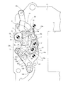
Next, the operation of this embodiment will be described. FIG. 1 shows a state immediately after the exposure operation is completed. Accordingly, the plurality of blades of the front blade group (not shown) are stored in a superimposed position in the lower portion of the opening 1a. Further, in the rear blade system, the
[0024]
In the setting operation of the present embodiment, a member (not shown) pushes the
[0025]
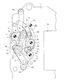
After that, when the
[0026]
Therefore, if the set operation is continued from the state of FIG. 3, the
[0027]
In this way, the set operation is continued, the plurality of blades of the leading blade group are in a deployed state and cover the opening 1a, and the five
[0028]
By the way, in the present embodiment, one member, which is usually called a rear blade driving member, is constituted by the first driving
[0029]
The state shown in FIG. 4 is not yet the completion state of the set operation. Next, the
[0030]
The
[0031]
When the release button of the camera is pressed during the next shooting, for example, due to the demagnetization signal of the leading blade electromagnet, first, the leading blade drive member (not shown) is rotated by the biasing force of the leading blade drive spring, The opening 1a is opened by the slit forming blades of the leading blade group. Thereafter, when a predetermined time elapses, for example, the locking of the
[0032]
In this way, the exposure operation is performed, and finally, a plurality of blades of the leading blade group are overlapped and stored at a position below the opening 1a, and the five blades of the trailing blade group are stored. The exposure operation ends when 7 to 11 are in the unfolded state and cover the opening 1a. In the case of the rear blade group, the exposure operation is performed as shown in FIG. Prior to the end, the
[0033]
On the other hand, in the case of the
[0034]
[Second Embodiment]
Next, the second embodiment will be described with reference to FIGS. 7 to 12. However, the configuration of the present embodiment can be the same as the configuration of the first embodiment described above. Therefore, substantially the same members and parts as those in the first embodiment are denoted by the same reference numerals, and description thereof is omitted to avoid duplication. Therefore, the configuration different from the case of the first embodiment will be described below. First, a
[0035]
In the present embodiment, the
[0036]
The
[0037]
Also, the
[0038]
Incidentally, the
[0039]
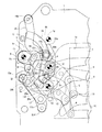
Next, the operation of the present embodiment will be described. Since a considerable portion has been clarified by the operation description of the first embodiment, the portion that does not need to be specifically described will be briefly described. To do. FIG. 7 shows a state immediately after the exposure operation is finished. Therefore, a plurality of blades of the front blade group (not shown) are stored at a position below the opening 1a. In the rear blade system, the
[0040]
When performing the set operation, when the
[0041]
After that, when the
[0042]
From the state shown in FIG. 9, the set operation is continued, the plurality of blades of the leading blade group completely covers the opening 1a, and the five
[0043]
On the other hand, the
[0044]
When the release button of the camera is pressed at the time of the next shooting, first, the leading blade driving member (not shown) rotates to open the opening 1a in the leading blade group. Thereafter, when a predetermined time has elapsed, the above-described locking with respect to the
[0045]
As already described, both of the two arms of the
[0046]
In the present embodiment, the two arms of the
[0047]
In each of the above-described two embodiments, the present invention has been described in the case where the present invention is applied to the drive system of the rear blade group. However, such a configuration can also be applied to the drive system of the front blade group. It is. In each of the above embodiments, the drive member is locked by the locking member at the exposure operation start position, which has been described as a so-called locking type shutter, but the present invention is not limited to the exposure operation. The present invention can also be applied to a so-called direct type shutter in which the driving member is directly held by the attractive force of the electromagnet immediately before the start. However, in that case, the exposure operation is started at the initial stage of photographing, instead of making the setting member return to the initial position when the setting operation is completed as in the above embodiments. Before, it will be returned to the initial position.
[0048]
Further, in each of the above-described embodiments, it has been described that a spring is hung between the
[0049]
【The invention's effect】
As described above, according to the present invention, the brake mechanism that brakes the drive member that operates the blade group at the end stage of the exposure operation and suppresses the bounce is manufactured with a smaller number of parts than in the conventional example. This is advantageous in terms of space and cost. In addition, since the number of spring parts can be reduced or eliminated, the set torque in the initial stage can be reduced, which is advantageous for power saving and cost reduction.
[Brief description of the drawings]
FIG. 1 is a plan view of a first embodiment showing a part of a left side when viewed from a subject side, and shows a state immediately after an exposure operation is finished.
FIG. 2 is a plan view of the first embodiment showing a state immediately after the set operation is started.
FIG. 3 is a plan view of the first embodiment showing a state in which the setting operation has advanced from the state shown in FIG. 2;
FIG. 4 is a plan view of the first embodiment showing an overset state.
FIG. 5 is a plan view of the first embodiment showing a set state.
FIG. 6 is a plan view of the first embodiment showing a state during the exposure operation.
FIG. 7 is a plan view of the second embodiment showing a part of the left side when viewed from the subject side, and shows a state immediately after the exposure operation is completed.
FIG. 8 is a plan view of a second embodiment showing a state immediately after the set operation is started.
9 is a plan view of a second embodiment showing a state in which the set operation has advanced from the state shown in FIG. 8. FIG.
FIG. 10 is a plan view of the second embodiment showing an overset state.
FIG. 11 is a plan view of a second embodiment showing a set state.
FIG. 12 is a plan view of the second embodiment showing a state during the exposure operation.
[Explanation of symbols]
1 Shutter base plate
1a opening
1b long hole
1c, 1d, 1e, 1f, 1g, 1h, 1i, 12b, 16b axis
1j stopper
1k restriction pin
2 cushioning members
3 First drive member
3a Locked part
3b Window
3c, 4a, 12d, 12e, 16a Roller
4 Second drive member
4b Drive pin
5,6 arm
7, 8, 9, 10, 11 feathers
12 set members
12a protrusion
12c Push pin
12f bent part
13, 23 First brake member
13a, 15a, 23a, 25a Driven part
13b Pushed pin
14 leaf spring
15, 25 Second brake member
15b, 23b, 25b deterrence unit
15c, 23c, 25c Constrained part
16 set operation members
17 Connecting member
Claims (5)
Priority Applications (1)
| Application Number | Priority Date | Filing Date | Title |
|---|---|---|---|
| JP2000131530A JP4364397B2 (en) | 2000-04-26 | 2000-04-26 | Focal plane shutter for camera |
Applications Claiming Priority (1)
| Application Number | Priority Date | Filing Date | Title |
|---|---|---|---|
| JP2000131530A JP4364397B2 (en) | 2000-04-26 | 2000-04-26 | Focal plane shutter for camera |
Publications (2)
| Publication Number | Publication Date |
|---|---|
| JP2001305605A JP2001305605A (en) | 2001-11-02 |
| JP4364397B2 true JP4364397B2 (en) | 2009-11-18 |
Family
ID=18640412
Family Applications (1)
| Application Number | Title | Priority Date | Filing Date |
|---|---|---|---|
| JP2000131530A Expired - Fee Related JP4364397B2 (en) | 2000-04-26 | 2000-04-26 | Focal plane shutter for camera |
Country Status (1)
| Country | Link |
|---|---|
| JP (1) | JP4364397B2 (en) |
Families Citing this family (4)
| Publication number | Priority date | Publication date | Assignee | Title |
|---|---|---|---|---|
| JP4931986B2 (en) * | 2009-11-30 | 2012-05-16 | 日本電産コパル株式会社 | Focal plane shutter for digital camera |
| JP5502534B2 (en) | 2010-03-11 | 2014-05-28 | 日本電産コパル株式会社 | Focal plane shutter for digital cameras. |
| JP5641852B2 (en) | 2010-09-30 | 2014-12-17 | 日本電産コパル株式会社 | Focal plane shutter for digital camera |
| JP5622601B2 (en) | 2011-01-31 | 2014-11-12 | 日本電産コパル株式会社 | Focal plane shutter for camera |
-
2000
- 2000-04-26 JP JP2000131530A patent/JP4364397B2/en not_active Expired - Fee Related
Also Published As
| Publication number | Publication date |
|---|---|
| JP2001305605A (en) | 2001-11-02 |
Similar Documents
| Publication | Publication Date | Title |
|---|---|---|
| JP4364397B2 (en) | Focal plane shutter for camera | |
| JPS6159493B2 (en) | ||
| JP5253903B2 (en) | Focal plane shutter for camera | |
| JP5622601B2 (en) | Focal plane shutter for camera | |
| JP4290284B2 (en) | Focal plane shutter for camera | |
| JP4334088B2 (en) | Focal plane shutter for camera | |
| JP2517632Y2 (en) | Focal plane shutter braking mechanism | |
| JP5117096B2 (en) | Focal plane shutter for camera | |
| JP2001021944A (en) | Double light shielding system focal plane shutter for camera | |
| JP2008275778A (en) | Focal plane shutter for camera | |
| JP4394294B2 (en) | Focal plane shutter | |
| JP4216620B2 (en) | Focal plane shutter for camera | |
| JP4416906B2 (en) | Focal plane shutter for camera | |
| JP3801728B2 (en) | Focal plane shutter | |
| JP4390926B2 (en) | Focal plane shutter for camera | |
| JP4203174B2 (en) | Double light-shielding focal plane shutter for cameras | |
| JP4386995B2 (en) | Focal plane shutter for camera | |
| JP4317283B2 (en) | Focal plane shutter for camera | |
| JP4364399B2 (en) | Double light-shielding focal plane shutter for cameras | |
| JP4105804B2 (en) | Focal plane shutter for camera | |
| JP4334092B2 (en) | Focal plane shutter for camera | |
| JP3990820B2 (en) | Focal plane shutter for camera | |
| JP3643426B2 (en) | Brake mechanism of focal plane shutter for camera | |
| JP3716035B2 (en) | Focal plane shutter | |
| JP2000314906A (en) | Focal plane shutter for double light-shielding system camera |
Legal Events
| Date | Code | Title | Description |
|---|---|---|---|
| A621 | Written request for application examination |
Free format text: JAPANESE INTERMEDIATE CODE: A621 Effective date: 20070411 |
|
| A977 | Report on retrieval |
Free format text: JAPANESE INTERMEDIATE CODE: A971007 Effective date: 20090713 |
|
| TRDD | Decision of grant or rejection written | ||
| A01 | Written decision to grant a patent or to grant a registration (utility model) |
Free format text: JAPANESE INTERMEDIATE CODE: A01 Effective date: 20090721 |
|
| A01 | Written decision to grant a patent or to grant a registration (utility model) |
Free format text: JAPANESE INTERMEDIATE CODE: A01 |
|
| A61 | First payment of annual fees (during grant procedure) |
Free format text: JAPANESE INTERMEDIATE CODE: A61 Effective date: 20090819 |
|
| FPAY | Renewal fee payment (event date is renewal date of database) |
Free format text: PAYMENT UNTIL: 20120828 Year of fee payment: 3 |
|
| R150 | Certificate of patent or registration of utility model |
Free format text: JAPANESE INTERMEDIATE CODE: R150 |
|
| FPAY | Renewal fee payment (event date is renewal date of database) |
Free format text: PAYMENT UNTIL: 20130828 Year of fee payment: 4 |
|
| R250 | Receipt of annual fees |
Free format text: JAPANESE INTERMEDIATE CODE: R250 |
|
| R250 | Receipt of annual fees |
Free format text: JAPANESE INTERMEDIATE CODE: R250 |
|
| LAPS | Cancellation because of no payment of annual fees |