JP4362607B2 - Bill movement device in bill storage device - Google Patents
Bill movement device in bill storage device Download PDFInfo
- Publication number
- JP4362607B2 JP4362607B2 JP2004042123A JP2004042123A JP4362607B2 JP 4362607 B2 JP4362607 B2 JP 4362607B2 JP 2004042123 A JP2004042123 A JP 2004042123A JP 2004042123 A JP2004042123 A JP 2004042123A JP 4362607 B2 JP4362607 B2 JP 4362607B2
- Authority
- JP
- Japan
- Prior art keywords
- banknote
- moving
- moving body
- bill
- movement
- Prior art date
- Legal status (The legal status is an assumption and is not a legal conclusion. Google has not performed a legal analysis and makes no representation as to the accuracy of the status listed.)
- Expired - Fee Related
Links
Images


Classifications
-
- B—PERFORMING OPERATIONS; TRANSPORTING
- B65—CONVEYING; PACKING; STORING; HANDLING THIN OR FILAMENTARY MATERIAL
- B65H—HANDLING THIN OR FILAMENTARY MATERIAL, e.g. SHEETS, WEBS, CABLES
- B65H29/00—Delivering or advancing articles from machines; Advancing articles to or into piles
- B65H29/38—Delivering or advancing articles from machines; Advancing articles to or into piles by movable piling or advancing arms, frames, plates, or like members with which the articles are maintained in face contact
- B65H29/46—Members reciprocated in rectilinear path
-
- G—PHYSICS
- G07—CHECKING-DEVICES
- G07D—HANDLING OF COINS OR VALUABLE PAPERS, e.g. TESTING, SORTING BY DENOMINATIONS, COUNTING, DISPENSING, CHANGING OR DEPOSITING
- G07D11/00—Devices accepting coins; Devices accepting, dispensing, sorting or counting valuable papers
- G07D11/10—Mechanical details
- G07D11/12—Containers for valuable papers
- G07D11/13—Containers for valuable papers with internal means for handling valuable papers
-
- B—PERFORMING OPERATIONS; TRANSPORTING
- B65—CONVEYING; PACKING; STORING; HANDLING THIN OR FILAMENTARY MATERIAL
- B65H—HANDLING THIN OR FILAMENTARY MATERIAL, e.g. SHEETS, WEBS, CABLES
- B65H2405/00—Parts for holding the handled material
- B65H2405/30—Other features of supports for sheets
- B65H2405/31—Supports for sheets fully removable from the handling machine, e.g. cassette
-
- B—PERFORMING OPERATIONS; TRANSPORTING
- B65—CONVEYING; PACKING; STORING; HANDLING THIN OR FILAMENTARY MATERIAL
- B65H—HANDLING THIN OR FILAMENTARY MATERIAL, e.g. SHEETS, WEBS, CABLES
- B65H2511/00—Dimensions; Position; Numbers; Identification; Occurrences
- B65H2511/20—Location in space
-
- B—PERFORMING OPERATIONS; TRANSPORTING
- B65—CONVEYING; PACKING; STORING; HANDLING THIN OR FILAMENTARY MATERIAL
- B65H—HANDLING THIN OR FILAMENTARY MATERIAL, e.g. SHEETS, WEBS, CABLES
- B65H2513/00—Dynamic entities; Timing aspects
- B65H2513/40—Movement
- B65H2513/41—Direction of movement
-
- B—PERFORMING OPERATIONS; TRANSPORTING
- B65—CONVEYING; PACKING; STORING; HANDLING THIN OR FILAMENTARY MATERIAL
- B65H—HANDLING THIN OR FILAMENTARY MATERIAL, e.g. SHEETS, WEBS, CABLES
- B65H2701/00—Handled material; Storage means
- B65H2701/10—Handled articles or webs
- B65H2701/19—Specific article or web
- B65H2701/1912—Banknotes, bills and cheques or the like
Landscapes
- Engineering & Computer Science (AREA)
- Mechanical Engineering (AREA)
- Physics & Mathematics (AREA)
- General Physics & Mathematics (AREA)
- Pile Receivers (AREA)
- Discharge By Other Means (AREA)
Description
本発明は、紙幣受入装置に着脱可能であって、紙幣受入装置で受け入れた紙幣を押込装置で保留部に押し込む紙幣収納装置の紙幣移動装置に関する。
詳しくは、自動販売機等に使用される小型の紙幣収納装置の紙幣移動装置に関する。
The present invention relates to a bill movement device of a bill storage device that is detachable from a bill receiving device and that pushes a bill received by a bill receiving device into a holding unit by a pushing device.
Specifically, the present invention relates to a bill moving device of a small bill storage device used in a vending machine or the like.
紙幣受入装置で受け入れた紙幣を、紙幣収納ボックスに内蔵する押込装置で保留部に押し込んで収納する技術が知られている(例えば、特許文献1参照。)。
このように、紙幣収納ボックスに押込装置が内蔵されている場合、紙幣収納ボックスの開口は、紙幣を受け入れるスリット状の開口のみにできるので防犯面において好ましい構造である。
A technique is known in which a banknote received by a banknote receiving device is stored by being pushed into a holding unit by a pressing device built in a banknote storage box (for example, see Patent Document 1).
Thus, when the pushing-in apparatus is built in the banknote storage box, the opening of the banknote storage box can be a slit-like opening for receiving banknotes, which is a preferable structure in terms of security.
しかし、この従来技術は紙幣を押し込めるプッシャを平行リンク機構に取り付け、この平行リンク機構に連結したリンク機構をスプリングによって引っ張ることによりプッシャを待機位置に保持する。
紙幣を押し込める場合、前記リンク機構をプーリにたすきがけしたワイヤによって引っ張って伸長させ、結果としてプッシャを平行移動させて紙幣を保留部に押し込める。
この従来技術は、紙幣を押し込める場合、スプリングに打ち勝ってリンク機構を駆動する必要があるため、消費電力が多いという問題がある。
However, in this prior art, a pusher that pushes in a bill is attached to a parallel link mechanism, and the pusher is held at a standby position by pulling the link mechanism connected to the parallel link mechanism with a spring.
When the banknote is pushed in, the link mechanism is pulled and extended by the wire drawn on the pulley, and as a result, the pusher is moved in parallel to push the banknote into the holding portion.
This conventional technique has a problem that power consumption is high because it is necessary to overcome the spring and drive the link mechanism when the bill is pushed in.
本発明の第1の目的は、紙幣を押し込める際の消費電力が少ない紙幣移動装置を提供することである。
本発明の第2の目的は、紙幣収納ボックスの小型化に適した紙幣移動装置を提供することである。
A first object of the present invention is to provide a banknote moving apparatus that consumes less power when a banknote is pushed in.
The second object of the present invention is to provide a bill moving device suitable for downsizing a bill storage box.
この目的を達成するため、本発明は以下のように構成されている。
紙幣受入装置に着脱可能であり保留部に紙幣を積層して収納する紙幣収納ボックス、前記紙幣収納ボックス内に配置され、受け入れた紙幣を保留部に移動させる移動体、前記移動体にリンク結合されるセクタギヤ、前記紙幣受入装置からの紙幣を受け入れるための待機位置に位置する前記移動体によって構成され、前記紙幣受入装置から受け取った紙幣を一時保留する一時保留部、前記紙幣受入装置に配置され、正逆方向に回転可能な回転駆動装置、前記紙幣収納ボックスに内蔵され、前記回転駆動装置の一方向への回転運動を受けて前記移動体を移動位置へ移動させて前記一時保留部に保留された紙幣に対し直交方向に移動させて前記一時保留された紙幣を前記保留部に移動させ、及び前記一方向とは逆方向の回転によって前記移動体を前記移動位置から前記待機位置へ移動させるため前記回転駆動装置と前記セクタギヤとを駆動連結するギヤ列からなる駆動装置、前記移動体の待機位置を検知する待機位置検知装置、前記移動体の移動位置を検知する移動位置検知装置、前記待機位置検知装置および前記移動位置検知装置からの検知信号に基づいて前記回転駆動装置の回転方向を切り替える制御装置、を含む紙幣収納装置における紙幣移動装置である。
In order to achieve this object, the present invention is configured as follows.
A bill storage box that can be attached to and detached from the bill accepting device and stacks and stores bills in a holding portion, a moving body that is disposed in the bill storage box and moves received bills to the holding portion, and is linked to the moving body. A sector gear, a temporary holding unit that temporarily holds a banknote received from the banknote receiving device, and is arranged in the banknote receiving device. A rotary drive device that can rotate in the forward and reverse directions, built in the banknote storage box, receives a rotational movement in one direction of the rotary drive device, moves the moving body to a moving position, and is held in the temporary holding unit. The banknotes temporarily moved are moved to the holding section, and the moving body is moved forward by rotation in a direction opposite to the one direction. Wherein for moving the moving position to the standby position rotary drive to consist of a gear train drivingly connecting said sector gear drive device, the standby position detecting device for detecting a standby position of the moving body, the moving position of the moving body It is a banknote moving apparatus in the banknote storage apparatus containing the moving position detection apparatus to detect, the control apparatus which switches the rotation direction of the said rotational drive apparatus based on the detection signal from the said standby position detection apparatus and the said movement position detection apparatus.
この構成において、移動体は、紙幣受入装置の回転駆動部からギヤ列からなる駆動装置を介して運動される。
すなわち、回転駆動部の一方向の回転により移動体はギヤ列による積極駆動によって待機位置へ向かって移動し、待機位置検知装置によって待機位置を検知された場合、前記回転駆動部は制御装置によって停止される。
結果として、移動体は待機位置に保持される。
In this configuration, the moving body is moved from the rotation driving unit of the banknote receiving device via a driving device including a gear train .
That is, the mobile body moves toward the standby position by the positive drive by the gear train due to the rotation of the rotation drive unit in one direction, and when the standby position is detected by the standby position detection device, the rotation drive unit is stopped by the control device. Is done.
As a result, the moving body is held at the standby position.
受け入れた紙幣を保留部へ押し込む場合、前記回転駆動部は前記と逆方向へ回転され、駆動装置を介して移動体はギヤ列による積極駆動によって保留部へ向かって移動する。
移動体が移動位置に達した場合、移動位置検知装置によって検知され、回転駆動部の回転は停止される。
その後回転駆動部は前記と逆方向に回転し、移動体はギヤ列による積極駆動によって待機位置へ向かって移動し、前記のように待機位置に保持される。
When the accepted banknote is pushed into the holding unit, the rotation driving unit is rotated in the opposite direction to the above, and the moving body moves toward the holding unit through the driving device by the positive drive by the gear train .
When the moving body reaches the moving position, it is detected by the moving position detecting device, and the rotation of the rotation driving unit is stopped.
Thereafter, the rotational drive unit rotates in the opposite direction to the above, and the moving body moves toward the standby position by the positive drive by the gear train , and is held at the standby position as described above.
したがって、移動体は回転駆動部の正逆回転によって紙幣の押込及び待機位置への復帰動をギヤ列による積極駆動によって行い、スプリング力に反して駆動されないので、消費電力が減少する。 Therefore, the moving body pushes the bill and returns to the standby position by the positive drive by the gear train by forward and reverse rotation of the rotation drive unit, and is not driven against the spring force, so that power consumption is reduced.
請求項2に係る発明は請求項1の発明において、前記移動体が、揺動レバによって往復運動され、前記揺動レバは前記紙幣収納ボックスの一端面に配置されたピボット軸に固定され、前記ピボット軸に固定されたセクタギヤは回転駆動装置に噛み合うギヤによって時計方向または反時計方向へ回動されることを特徴とする。 The invention according to claim 2 is the invention according to claim 1, wherein the movable body is reciprocated by a swinging lever, and the swinging lever is fixed to a pivot shaft disposed on one end surface of the bill storage box, The sector gear fixed to the pivot shaft is rotated clockwise or counterclockwise by a gear meshing with the rotation drive device.
この構成において、移動体はピボット軸によってピボット運動されるレバーによって直線運動する。
前記ピボット軸は、回転駆動装置に噛み合うギヤを介してセクタギヤによってピボット運動する。
したがって、移動体はピボット軸により駆動され、回転カムなどを使用しないので、移動体の駆動装置を小型化でき、結果として紙幣収納ボックスを小型化できる。
In this configuration, the moving body is linearly moved by a lever pivoted by a pivot shaft.
The pivot shaft is pivoted by a sector gear through a gear meshing with a rotary drive device.
Therefore, since the moving body is driven by the pivot shaft and does not use a rotating cam or the like, the driving device for the moving body can be reduced in size, and as a result, the bill storage box can be reduced in size.
請求項3に係る発明は請求項1の発明において、前記移動レバが揺動レバによって往復運動され、前記揺動レバは前記紙幣収納ボックスの一端面に配置された軸に回動可能に取り付けられたセクタギヤと一体に形成され、前記セクタギヤは前記回転駆動装置に噛み合うギヤによって時計方向または反時計方向へ選択的に回動されることを特徴とする。 According to a third aspect of the present invention, in the first aspect of the present invention, the moving lever is reciprocated by a swinging lever, and the swinging lever is rotatably attached to a shaft disposed on one end surface of the bill storage box. The sector gear is formed integrally with the sector gear, and the sector gear is selectively rotated clockwise or counterclockwise by a gear meshing with the rotation driving device.
この構成において、移動レバはセクタギヤのピボット運動によって直線運動する。
したがって、移動レバはセクタギヤと一体に揺動し、回転カムなどを使用しないので、移動体の駆動装置を小型化でき、結果として紙幣収納ボックスを小型化できる。
In this configuration, the moving lever moves linearly by the pivot movement of the sector gear.
Accordingly, since the moving lever swings integrally with the sector gear and does not use a rotating cam or the like, the driving device of the moving body can be reduced in size, and as a result, the bill storage box can be reduced in size.
紙幣受入装置に着脱可能であり保留部に紙幣を積層して収納する紙幣収納ボックス、前記紙幣収納ボックス内に配置され、受け入れた紙幣を保留部に移動させる移動体、前記紙幣受入装置に配置され正逆方向に回転可能な回転駆動装置、前記紙幣収納ボックスに内蔵され、前記回転駆動装置の回転運動を受けて前記移動体を往復運動させる揺動体を含む駆動装置、前記揺動体は前記紙幣収納ボックスの一端面に配置された軸に固定され、前記軸に取付られたセクタギヤが前記回転駆動装置に噛み合うギヤによって時計方向または反時計方向へ回動され、前記移動体の待機位置を検知する待機位置検知装置、前記移動体の移動位置を検知する移動位置検知装置、前記待機位置検知装置および前記移動位置検知装置からの検知信号に基づいて前記回転駆動装置の回転方向を切り替える制御装置、を含む紙幣収納装置における紙幣移動装置である。 A banknote storage box that is detachable from the banknote receiving device and that stores and stacks banknotes in a holding section, a mobile body that is disposed in the banknote storage box and moves the received banknotes to the holding section, and is disposed in the banknote receiving apparatus. A rotational drive device capable of rotating in forward and reverse directions, a drive device built in the banknote storage box and including a rocking body that reciprocally moves the movable body in response to a rotational motion of the rotary drive device, and the rocking body is the banknote storage A standby state in which a sector gear fixed to a shaft disposed on one end face of the box is rotated clockwise or counterclockwise by a gear meshing with the rotary drive device to detect a standby position of the moving body. Based on detection signals from a position detection device, a movement position detection device that detects a movement position of the moving body, the standby position detection device, and the movement position detection device Controller for switching the rotation direction of the rotation driving device, a bill moving apparatus in a bill storage apparatus including a.
図1は、本発明の実施例1の紙幣移動装置を内蔵した紙幣収納ボックスを紙幣受入装置から引き出した状態の斜視図である。
図2は、本発明の実施例1の紙幣移動装置のプッシャ駆動装置の説明図である。
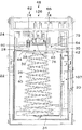
図3は、本発明の実施例1の紙幣移動装置を内蔵した紙幣収納ボックスを紙幣受入装置に装着した状態の断面図である。
図4は、本発明の実施例1の紙幣移動装置のプッシャが移動位置にある状態の断面図である。
図5は、本発明の実施例1の紙幣移動装置の説明用の断面図である。
図6は、本発明の実施例1の紙幣移動装置の待機位置検知装置の拡大断面図である。
図7は、本発明の実施例1の紙幣移動装置の移動位置検知装置の拡大断面図である。
図8は、本発明の実施例1の制御装置のブロック図である。
図9は、本発明の実施例1の作動説明用のフローチャートである。
FIG. 1 is a perspective view of a state in which a banknote storage box having a built-in banknote movement apparatus according to a first embodiment of the present invention is pulled out from a banknote receiving apparatus.
FIG. 2 is an explanatory diagram of the pusher driving device of the banknote moving device according to the first embodiment of the present invention.
FIG. 3 is a cross-sectional view of a state in which the banknote storage box including the banknote moving apparatus according to the first embodiment of the present invention is attached to the banknote receiving apparatus.
FIG. 4 is a cross-sectional view showing a state where the pusher of the banknote moving apparatus according to the first embodiment of the present invention is in the moving position.
FIG. 5 is a cross-sectional view for explaining the banknote moving apparatus according to the first embodiment of the present invention.
FIG. 6 is an enlarged cross-sectional view of the standby position detection device of the banknote moving device according to the first embodiment of the present invention.
FIG. 7 is an enlarged cross-sectional view of the movement position detection device of the banknote movement device according to the first embodiment of the present invention.
FIG. 8 is a block diagram of the control device according to the first embodiment of the present invention.
FIG. 9 is a flowchart for explaining the operation of the first embodiment of the present invention.
図1に示すように、紙幣受入装置10は、前方上部に紙幣識別装置12が配置され、その後方の金庫エリア14に紙幣収納ボックス16が挿入され、ロック装置(図示せず)でロックされる。
この紙幣受入装置10は、自動販売機や両替機等に内臓され、紙幣識別装置12の紙幣ガイド18のみが内蔵される機器の外側に配置される。
As shown in FIG. 1, the
The
次に紙幣収納ボックス16の構造を説明する。
図1および図5に示すように、紙幣収納ボックス16は、チャンネル形の板金製フレーム20に樹脂製の保留ボックス22を填め込み、その上に樹脂製の扁平ボックス形の収納ユニットボックス24を載置して構成され、全体として横長立方体である。
Next, the structure of the
As shown in FIG. 1 and FIG. 5, the
次に保留ボックス22の構造を主に図5を参照して説明する。
保留ボックス22は、後部側壁27が開口し、左側壁から中央へ向かって左天板28が突出し、右側壁から中央へ向かって右天板30が突出してそれら天板28および30間に紙幣の進行方向に伸びる押込通路32が形成されている。
Next, the structure of the
In the
保留ボックス22内の底壁34に一対のスプリング36が固定され、それら上端部に支持板38が固定された紙幣支持装置40が配置されている。
紙幣保留部42は、支持板38と左天板28の下面44と右天板30の下面46とに挟まれたエリアである。
後部側壁26の開口は、下端部を保留ボックス22にピボット運動可能に支持された蓋27で閉じられ、蓋27はロック装置29で収納ユニットボックス24にロックされる。
A pair of
The
The opening of the
次に収納ユニットボックス24の構造を主に図4を参照して説明する。
収納ユニットボックス24に、紙幣搬送装置48及び紙幣移動装置50が内臓されている。
収納ユニットボックス24の紙幣識別装置12の出口52に相対して下向き傾斜面54が形成され、保留ボックス22側の上向き傾斜面56とでラッパ形の紙幣入口58を形成している。
Next, the structure of the
In the
A downwardly
次に紙幣搬送装置48を説明する。
図5に示すように、紙幣搬送装置48は、左天板28の左上面60に相対配置した左ベルトユニット62と右天板30の右上面64に相対配置した右ベルトユニット66を含んでいる。
左右ベルトユニット62および66は、同一構成であるので、右ベルトユニット66によりその構造を説明する。
Next, the
As shown in FIG. 5, the
Since the left and
紙幣入口58に相対してタイミングプーリ68が配置され、蓋27側に配置したタイミングプーリ70との間にタイミングベルト74が巻き掛けられている。
このタイミングベルト74の下面は、右上面64からほぼ紙幣一枚の厚さに相当する間隔をもって配置されている。
タイミングプーリ68は、紙幣識別装置12の駆動モータ119から駆動されて図4において反時計方向に回転される。
A
The lower surface of the
The
しかし、プーリ68および70間のタイミングベルト74は、逃げることができるので、右上面64に接触していてもよい。
これらタイミングベルト74の下面と右上面64と左上面60で挟まれたエリアが紙幣移動通路75である。
タイミングプーリ68に相対して保留ボックス22の上向き傾斜面56に押さえローラ77が配置され、その周面がタイミングベルト74に弾性的に接触している。
However, since the
An area sandwiched between the lower surface of the
A
これにより、出口52から送り出される紙幣をタイミングベルト74の下面と押さえローラ77とで挟んで紙幣収納ボックス16の内部に引き込むとともに、タイミングベルト74の下面との摩擦力で右上面64と左上面60にガイドさせつつ紙幣を紙幣移動通路75に沿って紙幣収納ボックス16の内方に搬送する。
したがって、紙幣搬送装置48は、紙幣移動通路75において紙幣を搬送する機能を有しており、同一機能を有する他の機構に変更することが出来る。
Thus, the banknotes fed out from the
Therefore, the
次に紙幣移動装置50の構造を説明する。
紙幣移動装置50は、紙幣の押込用の板状の移動体76と移動体76の駆動装置78を含んでいる。
駆動装置78は、移動体76を平行移動させる平行移動装置80と、後述の回転駆動装置からの回転を揺動運動に変換する変換駆動装置81を含んでいる。
Next, the structure of the
The
The
図3及び図4に示すように、平行移動装置80は、移動体76を所定ストロークで平行移動させる機能を有している。
平行移動装置80は、同じ長さであって、中間を軸82でピボット運動可能に一体化した第1リンク84と第2リンク86とを有している。
第1リンク84の上端部に固定したピボット軸88は、収納ユニットボックス24の下面の軸受90にピボット運動可能に支持され、その下端部の軸92は、移動体76の上面に固定した第1ガイド板94の第1ガイド溝96にスライド可能に挿入されている。
したがって、第1リンク84は、揺動するレバである。
As shown in FIGS. 3 and 4, the
The
A
Therefore, the
第1ガイド溝96は、移動体76と平行に伸びている。
第2リンク86の下端部に固定した軸98が移動体76の上面に固定した軸受100にピボット運動可能に支持され、その上端部に固定した軸102は、収納ユニットボックス24の下面の第2ガイド板104のガイド孔106にスライド可能に挿入されている。
したがって、軸88がピボット運動することにより、移動体76は上下方向に平行移動する。
平行移動装置80の駆動源をピボット軸88にすることにより、回転円板などのクランク機構を使用しないので、収納ユニットボックス24の高さを低くすることができ、結果として紙幣収納ボックス16を小型化できる。
The
A shaft 98 fixed to the lower end portion of the
Accordingly, when the
By using the
次に図2を参照して変換駆動装置81を説明する。
変換駆動装置81は、図5に示すようにフレーム20と保留ボックス22との間のドライブエリア107に配置されている。
ドライブエリア107に突出したピボット軸88の左側端部にセクタギヤ108が固定され、ギヤ110、に噛み合っている。
Next, the
The
A
ギヤ110は、ギヤ113および114を介して紙幣受入装置10の回転駆動装置116であるギヤ118に駆動連結されている。
ギヤ110、113および114は、保留ボックス22の側面に回転自在に取り付けられている。
The
The
したがって、変換駆動装置81は、回転駆動装置116から回転力を受けてピボット軸88のピボット運動に変換する機能を有しており、同様の機能を有する他の機構に変更することができる。
変換駆動装置81を実施例のように保留ボックス22の側方に配置することにより、紙幣収納ボックス16の高さを低くすることができ、小型化に適している。
Therefore, the
By disposing the
回転駆動装置116のギヤ118は、駆動モータ119に固定された駆動ギヤ112に噛み合うギヤ122およびそれと一体のギヤ124を介して回転される。
この構成により、駆動ギヤ112の反時計方向の回転によってセクタギヤ108は反時計方向へピボット運動して移動体76を待機位置SBへ移動させる。
移動体76が待機位置SBにある場合、移動体76の下面は紙幣移動通路75よりも反紙幣保留部42側、すなわち、紙幣移動通路75よりも上方に位置する。
The
With this configuration, the
When the moving
セクタギヤ108が最も時計方向にピボット運動された場合、移動体76は紙幣移動通路75を横断した後、押込通路32を通って紙幣保留部42へ進行し、紙幣を介して支持板38を所定の移動位置MMまで押し込める。
この一連の移動によって、紙幣移動通路75に位置する紙幣は、押込通路32をU状になって通過した後、紙幣保留部42に移動される。
移動体76が紙幣保留部42から退出した場合、紙幣は下面44および46と支持板38との間に保持されて保留部42に積層状態に保留される。
When the
By this series of movements, the banknote located in the
When the moving
次に紙幣移動装置50の待機位置検知装置126を図6を参照して説明する。
待機位置検知装置126は、待機投受光部128、待機導光部130および待機検知片132を含んでいる。
待機投受光部128は、投光部132と受光部134を有している。
投受光部128は、紙幣受入装置10の金庫エリア14の上内面に固定されている。
基板136に投光部132と受光部134が僅かに離れて下向きに固定されている。
投光部132は、発光ダイオードなどの発光素子138とシリンダ140を含み、受光部134は、フォトトランジスタ等の受光素子142とシリンダ144を含んでいる。
Next, the standby
The standby
The standby light projecting / receiving
The light projecting / receiving
The
The
発光素子138は基板136の下方に位置するカバー146から垂直に上方に伸びるシリンダ140の上端部に挿入され、その下端開口148からシリンダ140の直径の二倍以上離れて配置されている。
受光素子142も同様にシリンダ144に挿入されている。
このように、発光素子138および受光素子142がシリンダ140、144の上部であって、かつ、下端開口148、150から直径以上の上方に配置されている場合、シリンダ140および144は上端が発光素子138または受光素子142によって閉止されているため、シリンダ内に上昇気流が発生しない。
The
Similarly, the light receiving element 142 is inserted into the cylinder 144.
As described above, when the
したがって、塵埃が金庫エリア14に進入した場合、発光素子138または受光素子142に達する気流が無いので塵埃が発光素子138または受光素子142に付着することがない。
僅かに上昇気流が生じた場合、シリンダの直径以上内部に入る上昇気流は発生しないので、塵埃が発光素子140または受光素子142に付着することがない。
また、発光素子138からの投射光は、シリンダ140の壁面によって反射されて案内され、受光素子142に入光する光はシリンダ144の壁面によって反射されて案内されるので、その拡散を抑制することができる。
しかし、シリンダ140及び144は、投光部132及び受光部134において、必要条件ではない。
Therefore, when dust enters the
When a slight updraft is generated, no updraft entering the inside of the cylinder diameter or more is generated, so that dust does not adhere to the
In addition, the projection light from the
However, the
投受光部128に相対して待機導光体130が紙幣収納ボックス16の天板152の裏面にブラケット(図示せず)により固定されている。
待機導光体130は、投光部132の真下において垂直方向に伸びる投導光体154と受光部134の真下において垂直方向に伸びる受導光体156とを有し、上端および中間部においてステー158、160によって連結し、門形である。
このように投導光体154と受導光体156とを一体化すると、部品点数が減少して組み立て性やコストにおいて有利である。
しかし、投導光体154と受導光体156とに分離して取り付けてもよい。
The standby
The standby
If the light projecting
However, the light projecting
投導光体154の上端面が受光面162であり、下端の反射面164は受光面162の延長線に対して45度の角度で傾斜しており、その側面が検知投光面166である。
受導光体156の上端面が受光面168であり、下端の反射面170は受光面168の延長線に対して45度の角度で傾斜しており、その側面が検知受光面172である。
反射面164と反射面170は、向かい合って配置されている。
検知投光面166と検知受光面172は平行に垂直方向に伸び、それらの間に検知エリア174を構成している。
The upper end surface of the light projecting
The upper end surface of the light receiving and guiding
The
The detection
したがって、発光素子138から投射された光は、受光面162から投導光体154に進行して反射面164によって横方向に反射され、検知投光面166から検知エリア174を横断して検知受光面172から受導光体156に入る。
受導光体156内の光は、反射面170に反射されて上方に向かい、投光面168から出て受光素子142に入光する。
Therefore, the light projected from the
The light in the light receiving / guiding
待機検知片132は、移動体76の紙幣識別装置12側端部の上面に垂直に固定され、移動体76が待機位置SBにあるとき、検知エリア174に位置し、前記光を遮断する。
したがって、受光素子142が受光しない場合、移動体76が待機位置SBにあるものと判別する。
移動体76が待機位置SBになったことを検知して、モータ119、したがって、駆動ギヤ112の回転を停止して待機位置SBに保持する。
The
Therefore, when the light receiving element 142 does not receive light, it is determined that the moving
It is detected that the moving
次に、移動位置検知装置176を図4及び図7を参照して説明する。
移動位置検知装置176は、移動投受光部178、移動導光体180および移動検知片182を含んでいる。
移動投受光部178は、投光部184と受光部186を有している。
投光部184は、発光素子188がシリンダ190に挿入されている
受光部186は、受光素子192がシリンダ194に挿入されている。
これら投光部184と受光部186の構造は、前記待機位置検知装置126の投光部132および受光部134と同様である。
Next, the movement
The movement
The moving light projecting / receiving
In the
The structures of the
移動投受光部178に相対して移動導光体180が天板152の裏面にブラケット(図示せず)により固定されている。
移動導光体180は、投光部184の真下において垂直方向に伸びる投導光体196と受光部186の真下において垂直方向に伸びる受導光体198とを有し、上端および中間部においてステー200、202によって連結され、門形である。
このように投導光体196と受導光体198とを一体化すると、部品点数が減少して組み立て性やコストにおいて有利である。
しかし、投導光体196と受導光体198とに分離して取り付けてもよい。
A moving
The moving
If the light projecting
However, the light projecting
投導光体196の上端面が受光面204であり、下端の反射面206は受光面204の延長線に対して45度の角度で傾斜しており、その側面が検知投光面208である。
受導光体198の上端面が投光面210であり、下端の反射面212は投光面210の延長線に対して45度の角度で傾斜しており、その側面が検知受光面214である。
The upper end surface of the light projecting
The upper end face of the受導the light 198 is light-projecting
検知投光面208と検知受光面214は平行に垂直方向に伸び、それらの間に検知エリア216を構成している。
反射面206と212は互いに向かい合っている。
したがって、発光素子188から投射された光は、受光面204から投導光体196に進行して反射面206によって横方向に反射され、検知投光面208から押込検知エリア216を横断して検知受光面214から受導光体198に入る。
受導光体198内の光は、反射面212に反射されて上方に向かい、投光面210から出て受光素子192に入光する。
The detection
The
Therefore, the light projected from the
The light in the light receiving / guiding
移動検知片182は、駆動装置78の軸102に固定され、一体にスライドし、移動体76が最も押し込んだ移動位置(最下位置)MMにあるとき、検知エリア216に位置し、前記光を遮断する。
したがって、受光素子192が受光しない場合、移動体76が移動位置MMにあるものと判別する。
移動体76が移動位置MMにあることが判別された場合、モータ119、したがって駆動ギヤ112は時計方向の回転が停止された後、反時計方向に回転される。
これにより、移動体76は移動位置MMから待機位置SBに向かって移動する。
The
Therefore, when the
When it is determined that the moving
As a result, the moving
次に制御装置217を図8を参照して説明する。
制御装置217は、押込信号P、待機位置検知装置126および移動位置検知装置176からの検知信号に基づいて駆動モータ119を正転または逆転制御する。
具体的には、マイクロプロセッサ等で構成される。
Next, the
The
Specifically, it is composed of a microprocessor or the like.
次に本実施例の作用を図9のフローチャートを参照しつつ説明する。
スタンバイ状態において、移動体76は待機位置SBに保持され、待機検知片132は検知エリア174に位置し、移動検知片182は検知エリア216から外れている。
ステップS1において、押込信号Pが存在するか判別し、押込信号Pが存在する場合、ステップS2に進む。
ステップS2において、駆動モータ119が正転し、駆動ギヤ112が図2において時計方向に回転し、ステップS3に進む。
Next, the operation of the present embodiment will be described with reference to the flowchart of FIG.
In the standby state, the moving
In step S1, it is determined whether or not the push signal P exists. If the push signal P exists, the process proceeds to step S2.
In step S2, the
駆動ギヤ112の回転により、回転駆動装置118を介して紙幣収納ボックス16の変換駆動装置81が駆動される。
すなわち、ギヤ114、113および110を介してセクタギヤ108が時計方向へピボット運動され、結果としてピボット軸88が同方向へピボット運動する。
このピボット運動により、第1リンク84が図4において時計方向にピボット運動するので、軸92が第1ガイド溝96を図3において左方へスライドする。
同様に軸82を介して第2リンク86が軸98を支点に反時計方向へピボット運動するので、軸102が第2ガイド溝106を図3において左方へスライドする。
The
That is, the
Due to this pivoting movement, the
Similarly, since the
結果として、移動体76が紙幣移動通路75を横断し、通路32を通って紙幣保留部42に平行移動する。
換言すれば、移動体76は、待機位置SBから下方へ平行に移動し、紙幣保留部42内の図4に示す移動位置MMへ移動する。
この過程で紙幣移動通路75に位置する紙幣は、紙幣保留部42に押し込まれる。前記軸102の移動により、移動検知片182が押込検知エリア216に進入した場合、発光素子188からの投射光は移動検知片182によって遮断されるため、受光素子192が受光しないので、押込検知装置176は移動位置信号を出力する。
As a result, the moving
In other words, the moving
In this process, the banknote located in the
ステップS3において移動位置信号が判別された場合、ステップS4においてモータ119は停止され、次いでステップS5において逆転される。
すなわち、駆動ギヤ112が反時計方向に回転されるため、セクタギヤ108も同方向にピボット運動し、移動体76は待機位置へ向かって移動する。
この移動により、待機検知片132は待機検知エリア174に進入し、検知投光面166からの光を遮断する。
これにより、受光素子142は受光しなくなるので、待機位置信号を出力する。ステップS6においてこの待機位置信号が判別されるとステップS7に進み、モータ119は停止される。
したがって、移動体76は待機位置SBに保持される。
If the movement position signal is determined in step S3, the
That is, since the
By this movement, the
As a result, the light receiving element 142 does not receive light and outputs a standby position signal. When the standby position signal is determined in step S6, the process proceeds to step S7, and the
Accordingly, the moving
図10は、本発明の実施例2の紙幣受入装置の側面一部断面図である。
図11は、本発明の実施例2の紙幣受入装置の縦断面図である。
図12は、本発明の実施例2の紙幣収納ボックスの斜視図である。
図13は、図12におけるC面での紙幣収納ボックスの断面図である。
図14は、本発明の実施例2の紙幣収納ボックスの内部斜視図である。
図15は、本発明の実施例2の作動説明図裏面図(移動状態)である。
図16は、本発明の実施例2の作動説明裏面図(待機状態)である。
図17は、本発明の実施例2の作動説明図(収納状態)である。
FIG. 10 is a partial cross-sectional side view of the banknote receiving device according to the second embodiment of the present invention.
FIG. 11: is a longitudinal cross-sectional view of the banknote acceptance apparatus of Example 2 of this invention.
FIG. 12 is a perspective view of the banknote storage box according to the second embodiment of the present invention.
FIG. 13 is a cross-sectional view of the banknote storage box on the C surface in FIG.
FIG. 14 is an internal perspective view of the banknote storage box according to the second embodiment of the present invention.
FIG. 15 is a back view (moving state) illustrating the operation of the second embodiment of the present invention.
FIG. 16 is a back view for explaining the operation of the second embodiment of the present invention (standby state).
FIG. 17 is an operation explanatory diagram (storage state) of the second embodiment of the present invention.
実施例1と同一部位には同一符号を付して説明を省略し、異なる構成を説明する。
図12及び13に示すように、紙幣収納ボックス316は全体において箱形の板金製フレーム322の外側に箱形のカバー324を被せて構成されている。
The same parts as those in the first embodiment are denoted by the same reference numerals, description thereof will be omitted, and different configurations will be described.
As shown in FIGS. 12 and 13, the
次にフレーム322の構造を図13および図14を参照して説明する。
なお図13、14は、後方から見た図であるので、説明における左右は図における左右と逆である。
左側壁328と右側壁330が、板状のベース326の両側端部から立設されている。
左側壁328および右側壁330からベース326と平行に左天板332および右天板334が向かい合って伸び、それら先端間に隙間336が形成されている。
Next, the structure of the
Since FIGS. 13 and 14 are views seen from the rear, the left and right in the description are opposite to the left and right in the figure.
A
A left
これらベース326、側壁328、330及び天板332、334で囲まれた空間338に、紙幣を内部に引き入れるための紙幣搬送装置340、引き入れた紙幣を保留部342に移動するための移動体344、保留部342に紙幣を保持するための押圧装置346が配置されている。
また、フレーム322とカバー324との間の薄い駆動装置空間347には、移動体344を移動させるための駆動装置348が配置されている。
In a space 338 surrounded by the
A driving
次に搬送装置340を図13及び14を参照して説明する。
隙間336において、矩形板状のサポータ350の一端部が左天板332および右天板334に固定されている。
サポータ350の他端部は、保留部342側に伸び、その端部に紙幣搬送装置340が取り付けられている。
Next, the conveying
In the
The other end portion of the
紙幣搬送装置340は、プーリー装置352と搬送体354を含んでいる。
プーリー装置352は、サポータ350に回転自在に支持されたシャフト356及びその端部に固定された歯付きプーリ358を含んでいる。
しかし、歯付きプーリ358は、通常の溝付きプーリ等に変更することができる。
このプーリ装置352がサポータ350の長手に沿って複数、本実施例においては4ユニット配置されている。
The
The
However, the
A plurality of
両端部のプーリ358には搬送体354が巻き掛けられ、中間部のプーリ358は、搬送体354が紙幣との接触を保つよう搬送体354の移動を制限している。
したがって、紙幣を確実に搬送できる場合、中間のプーリ装置352を配置しないことができる。
一端部のプーリ装置352は、図12に示すように収納ボックス316の側壁362に位置するスリット状の受入口364に位置し、かつ、図14に示すようにシャフト366は駆動装置空間347に伸び、その端部に被動ギヤ368が固定されている。
A
Therefore, when the banknote can be reliably conveyed, the
As shown in FIG. 12, the
この被動ギヤ368は、図10に示すように、紙幣識別装置12の搬送装置(図示せず)駆動用モータ371(図11参照)によって駆動される駆動ギヤ370に伝達機構372を介して駆動連結されている。
搬送体354は、本実施例では歯付きベルトであるが、平ベルト、ロープ等の柔軟性を有する材料によりリング状に構成したものに変更することができる。
As shown in FIG. 10, the driven
The
換言すれば、搬送体354は、紙幣と摩擦接触して一方向に搬送する機能を有していればよい。
この搬送体354の紙幣との接触部位が搬送部360である。
前記端部のプーリ装置352に巻き掛けた搬送体354に弾性的に接するようにローラ374が配置されている。
In other words, the
A contact portion of the
A
したがって、紙幣識別装置12によって判別された真紙幣は、受入口364に送られ、搬送体354とローラ374とにより挟まれ、搬送部360の搬送方向へ送られる。
すなわち、紙幣と接触する搬送部360は、被駆動時において緩み側である。
換言すれば、真紙幣は収納ボックス316内に引き込まれ、搬送部360との摩擦接触により、搬送部360の進行方向に搬送される。
Therefore, the true banknote discriminated by the
That is, the
In other words, the true banknote is drawn into the
搬送装置340は、実施例のようにサポータ350の両側に配置することが好ましい。
なぜなら、紙幣との摩擦力を高め、かつ、紙幣に対し平面的に摩擦力を付与するので、紙幣を平行移動させることができるからである。
しかし、搬送部360の幅を広げる等することにより、搬送装置340は、サポータ350の一側にのみに配置されることができる。
搬送装置340は、紙幣識別装置12により判別された真紙幣を収納ボックス316内に引き入れる機能を有する。
したがって、本実施例の他、同様の機能を有する他の装置に変更可能である。
The conveying
This is because the frictional force with the banknote is increased and the frictional force is applied to the banknote in a planar manner, so that the banknote can be translated.
However, the conveying
The
Therefore, in addition to the present embodiment, it can be changed to another device having the same function.
次に移動体344を説明する。
移動体344は、搬送装置340の側方に位置するチャンネル形の左移動体378及び右移動体380を含んでいる。
左移動体378及び右移動体380は、同一構造であって、搬送装置340に対し左右対称に空間338内に配置されているので、左移動体378を代表して説明する。
左移動体378は、スライダ部382、及び、スライダ部382の端部に位置し、スライダ部382に対し直交方向に延びる第1保持部384とによりT字形に形成されている。
Next, the moving
The moving
Since the left moving
The left moving
第1保持部384は、スライダ部382に対し直角に折り曲げられ、ベース3
26、換言すれば、引き入れられた紙幣とほぼ平行をなしている。
第1保持部384の下方に所定の間隔をもって樹脂で成形された板状の第2保持
部386がスライダ部382に固定されている。
第1保持部384の下面383、第2保持部386の上面385およびスライダ部382の側面387によって三方を囲まれ、所定の幅と高さを有する(図13参照))左保持部388が構成されている。
左保持部388の高さは、紙幣収納ボックス316を小型化するため、紙幣がスムーズに移動可能な範囲で可及的に薄いことが好ましい。
The
26. In other words, it is substantially parallel to the drawn banknote.
A plate-like
The
The height of the
左保持部388は、樹脂によりスライダ部382と共にF形状に一体成形することも可能である。
第2保持部386は、搬送装置340によって紙幣が湾曲された場合、保留部342に保留されている紙幣に接触しないよう所定の厚みに形成されている。
第2保持部386の受入口364側は、紙幣を左保持部388に案内するよう斜面390になっている(図11参照)。
右移動体380にも同様に右保持部392が形成されている。
The
The
The receiving
Similarly, a
スライダ部382は、左側壁328の内面に固定された樹脂製のガイド部394の溝396にその長手方向に移動可能に配置されている。(図14においては、右側壁330に固定されたガイド部394の溝396に配置されている)。
また、図10に示すようにスライダ部382の下部から外方に向かって突出するガイドピン398が、右側壁330に形成された長孔400にスライド可能に挿入されている(左側も同様である)。
したがって、左移動体378及び右移動体380は、長孔400によって案内されつつ直線的に往復運動することができる。
The
Further, as shown in FIG. 10, a
Therefore, the left moving
図11に示すように、右移動体380は、収納ボックス316が待機状態の場合、受入口364の延長上に右保持部392が位置するよう配置される。
左移動体378も同様に配置される。
したがって、左保持部388及び右保持部392は、待機状態において、受入口364に続いて伸びる仮想平面393に位置し(図14参照)、搬送装置340によって搬送される紙幣の端部が移動する。
図11において明らかなように、実施例において仮想平面393はほぼ垂直であるので、紙幣がこの仮想平面393内を移動する場合、重力によって引き下げられる効果がある。
As shown in FIG. 11, when the
The left moving
Accordingly, the
As apparent from FIG. 11, the
引き入れられた紙幣の後端部がローラ374を通過したことを図示しないセンサが検知し、モータ371を停止し、搬送装置340による紙幣の搬送を停止する。
これにより、紙幣はその左右端部がそれぞれ左保持部388、右保持部392に位置した状態で一時保持される。
したがって、仮想平面393は、紙幣の一時保留部395でもある。
また、左移動体378及び右移動体380は、仮想平面393に対し直交方向に移動可能である。
A sensor (not shown) detects that the trailing edge of the drawn banknote has passed the
As a result, the banknote is temporarily held with its left and right end portions positioned at the
Therefore, the
Further, the left moving
すなわち、紙幣の端部が第2保持部386の左裏面406及び右裏面408よりも紙幣押え404側に位置するよう、移動体344はサポータ350に沿って左天板332及び右天板334側に移動した移動位置MM(一点鎖線示)へ移動可能である。
図13に示すように、搬送部360が、第2保持部386の紙幣の案内面である上面385とほぼ面一になるように配置することが好ましい。
すなわち、収納ボックス316内の紙幣は、搬送部360との摩擦のみによって引き入れられるため、搬送部360との適度な摩擦力を付与する必要があるためである。
That is, the moving
As shown in FIG. 13, it is preferable that the
That is, since the banknotes in the
詳述すれば、紙幣は搬送部360との接触によって一面に搬送力を受け、他面は第2保持部386の上面385から制動力を受ける。
この制動力は、紙幣と第2保持部386との間の接触面積、接触圧力及び摩擦係数によって決定される。
More specifically, the banknote receives a conveying force on one side by contact with the conveying
This braking force is determined by the contact area between the bill and the
紙幣との接触部である搬送部360を緩み側に設定し、かつ、搬送部360の静止状態において、第2保持部386の上面385と面一に設定することにより、搬送装置340の作動時において、搬送部360は緩み、搬送部360が僅かに第2保持部386側に移動するため、紙幣と搬送部360との接触圧力が高まり、適当な摩擦力になる。
When the
したがって、搬送部の位置調整時の目安が明確であるため、位置調整が容易である利点を有する。
なお、紙幣との適度な摩擦力と耐久性を両立するため、搬送体354の紙幣との接触面はウレタンゴムであることが好ましい。
移動体344は、搬送装置340によって収納ボックス316に引き入れられた紙幣を保留部342に移動する機能を有する。
したがって、同機能を有する他の装置に変更可能である。
Therefore, since the guideline at the time of position adjustment of the transport unit is clear, there is an advantage that the position adjustment is easy.
In order to achieve both an appropriate frictional force with the banknote and durability, the contact surface of the
The moving
Therefore, it can be changed to another device having the same function.
次に押圧装置346を図13を参照して説明する。
押圧装置346は、紙幣に接触する紙幣押さえ404、及び、紙幣押さえ404を第2保持部386の左裏面406及び右裏面408側に付勢する付勢体410を含んでいる。
紙幣押さえ404は、板状であり、左右のスライダ部382の間において移動可能に配置される。
Next, the pressing device 346 will be described with reference to FIG.
The pressing device 346 includes a
The
付勢体410は、一端をベース326に固定され、他端を紙幣押さえ404に固定したスプリング412である。
付勢体410の付勢力は、紙幣の保留量を増すため紙幣の積み重ね厚みを減少させるとと共に保留部342に保留される紙幣が座屈しないように保持し、さらに、搬送装置340と紙幣との間に挟まれた紙幣の両端部が移動体344によって移動される場合、紙幣が搬送装置340と保留された紙幣との間に保持されるように設定する。
したがって、付勢体410は同機能を有する他の装置に変更することができる。
The biasing
The urging force of the urging
Therefore, the biasing
なお、保留部342は、左裏面406、右裏面408、搬送部360及び紙幣押さえ404によって挟まれた空間である。
したがって、紙幣が保留されていない場合、紙幣押さえ404は、左裏面406および右裏面408に接触する。
The holding
Therefore, when no banknote is held, the
次に駆動装置348の構造を図10および図14を参照して説明する。
駆動装置348は、左側壁328および右側壁330にそれぞれ取り付けられた左駆動装置424及び右駆動装置426を備えている。
左駆動装置424と右駆動装置426は、同一構造であるので、左駆動装置424を代表して説明する。
右駆動装置426の同一部には同一符号を付してある。
Next, the structure of the
The
Since the
The same parts of the
左側壁328から駆動空間347に突出する固定軸428に揺動レバ430がピボット運動可能に取り付けられている。
揺動レバ430の一端部の長孔432にスライダ部382から突出するピン434がスライド可能に挿入されている。
ピン434は、左側壁328の長孔435によって案内されつつ移動する。
A swinging
A
The
揺動レバ430の他端部に固定軸428を中心とするセクタギヤ436が形成され、左側壁328に回転自在に取り付けられたギヤ438、440を介して紙幣受入装置10の駆動部441に配置した回転駆動装置443、例えば電動モータ445(図11参照)の出力軸に固定したギヤ442およびギヤ444を介して駆動連結されている。
すなわち、収納ボックス316が金庫スペース314に装着された場合、ギヤ440とギヤ444が噛み合うように設定されている。
したがって、ギヤ442が時計方向に回転した場合、揺動レバ430は図10において時計方向に回動され、移動体344を紙幣収納方向に移動させ、移動位置MMへ移動させる。
A
That is, when the
Therefore, when the
ギヤ442が反時計方向に回転した場合、揺動レバ430は図10において反時計方向に回動され、移動体344が待機位置SBに移動される。
また、セクタギヤ436とギヤ438の歯が常に接触するよう揺動レバー430は、左側壁328から突出する係止片431との間に引っ掛けたスプリング433により移動体344が待機位置SBに向かうよう付勢されている。
When the
In addition, the
駆動装置348は、移動体344を仮想平面393、換言すれば、紙幣の面に対し直交方向に往復移動させる、機能を有する。
したがって、駆動装置348は、同様の機能を有する他の装置に変更できる。
なお、ベース326の外面には、紙幣収納ボックス316搬送用のハンドル450が取り付けられている。
また、図10に示すように、紙幣収納ボックス316の側壁362に相対する側壁452の一端部は、フレーム322に対しピボット運動可能に取り付けられ、保留部342に保留された紙幣を取り出すため、ロックを外すことにより開閉可能である。
The
Therefore, the driving
A
Also, as shown in FIG. 10, one end of the
次に移動体344の待機位置検知装置460を図15を参照して説明する。
待機位置検知装置460は、実施例1と同様に待機投受光部及び待機導光体462および待機検知片464を含んでいる。
換言すれば、待機投受光部は、紙幣受入装置10の金庫スペース314の上内面に配置されている。
Next, the standby
The standby
In other words, the standby light projecting / receiving unit is disposed on the upper inner surface of the
前記待機投受光部に相対して実施例1と同様に門形の待機導光体462が紙幣収納ボックス316の側壁362の裏面にブラケット(図示せず)により固定されている。
待機導光体462の受光面466、投光面468が側壁362の表面に位置している
A portal-shaped standby
The
待機検知片464は、右側壁330に固定された軸470にピボット運動可能に中間を取り付けたレバー472の一端部である。
レバー472の他端部と右側壁330から突出した係止片474との間に引っ掛けたスプリング476によって、待機検知片464が待機導光体462の検知エリア(図示せず)から退出するよう付勢されている。
The
The
レバー472の他端部は、ピン398の移動経路に位置し、移動体344が待機位置SBに位置する場合、ピン398によって移動され、図15に示すように待機検知片464が待機導光体462の検知エリアに位置し、光を遮断する。
この場合、移動体344が待機位置SBにあるものと判別する。
The other end of the
In this case, it is determined that the moving
移動体344が移動位置MMへ向かって移動する場合、レバー472はスプリング476によって図15において反時計方向へピボット運動し、待機導光体462の検知エリアから退出した所定位置で右側壁330から突出するストッパ478に停止される(図16参照)。
移動体344が待機位置SBになったことを検知して、モータ443、したがって、駆動ギヤ442の回転を停止して待機位置SBに保持する。
When the moving
Detecting that the moving
次に、移動位置検知装置480を図10及び図17を参照して説明する。
移動位置検知装置480は、移動投受光部(図示せず)、移動導光体482および移動検知片484を含んでいる。
移動投受光部は、実施例1と同様な投光部と受光部を有している。
移動投受光部に相対して移動導光体482が側壁362の裏面にブラケット(図示せず)により固定されている。
Next, the movement
The movement
The moving light projecting / receiving unit has the same light projecting unit and light receiving unit as in the first embodiment.
A moving
移動導光体482は、実施例1と同様に門形に形成され、移動検知エリア486を有し、さらにアングル形に屈曲している(図14参照)。
移動受光面488及び移動投光面490は、側壁362と面一に配置されている。
移動検知片484は、左側壁328から駆動装置空間347に突出する軸492にピボット運動可能に取り付けられたレバー494の一端部である。
The moving
The moving
The
レバー494は、左側壁から突出する係止片495との間に引っ掛けられたスプリング497によって移動検知片484が移動導光体482の検知エリア486から退出するよう付勢されている。
移動体344が移動位置MMにあるとき、レバー494の他端部がガイドピン398によって図17に示すように時計方向に回動され、移動検知片484が検知エリア486に位置し、前記光を遮断する。
The
When the moving
したがって、移動導光体482の移動受光面488において受光しない場合、移動体344が移動位置MMにあるものと判別する。
移動体344が移動位置にあることが判別された場合、モータ443、したがって駆動ギヤ442は時計方向の回転が停止された後、反時計方向に回転される。
これにより、移動体344は移動位置MMから待機位置SBに向かって移動する。
移動体344が待機位置SBにある場合、レバー494は左側壁328から突出するストッパ491に係止され、移動検知片484が検知エリア486から外れた位置に保持される。
Therefore, when no light is received by the moving
When it is determined that the moving
Thereby, the moving
When the moving
なお、紙幣収納ボックス検知用の光導体496及び紙幣位置検知装置の紙幣光導体498、500も側壁362に面一に配置されている。
本実施例2も実施例1と同様の制御装置216によって、図9に示すフローチャートと同様のプログラムにより制御される。
Note that the
The second embodiment is also controlled by the
次に本実施例2の作用を説明する。
収納ボックス316が金庫スペース314の所定位置に収納された後、紙幣受入装置10の電源スイッチ(図示せず)を投入する。
内蔵の制御装置は、移動体344が待機位置SBにおいて待機位置検知装置460よって検知されない場合、モータ445が回転し、ギヤ442が図10において反時計方向に回動され、揺動レバ430を反時計方向に回動させる。
Next, the operation of the second embodiment will be described.
After the
When the moving
これにより、ピン434を介してスライダ部382、したがって、移動体344が図10において右方に移動され、待機位置SBへ移動される。
移動体344が待機位置SBに位置した場合、ピン398によってレバー472が時計方向にピボット運動され、図15に示す状態になる。
これによって、待機検知片464が待機導光体462の検知エリアに進出し、検知光を遮断するため、待機位置検知装置460によって検知される。
この検知に基づいて、モータ443は停止され、ギヤ442の回転が停止され、待機状態になる。
As a result, the
When the moving
As a result, the
Based on this detection, the
待機状態において、左移動体378及び右移動体380の左保持部388及び右保持部392は、図11に示すように受入口364の真下に位置し、ほぼ垂直方向に延びている。
紙幣BNが紙幣ガイド18に沿って挿入された場合、その紙幣BNは図示しないセンサによって検知され、搬送モータ371が回転する。
In the standby state, the
When the banknote BN is inserted along the
この搬送モータ371の回転によって紙幣識別装置12の搬送装置(図示せず)が作動されると共に駆動ギヤ370および伝達機構372を介して被動ギヤ368が回転される。
これにより、シャフト366が回転され、搬送装置340が紙幣BNを一時保留部395への引き入れ動作を開始する。
識別装置12によって真紙幣と判別された紙幣BNは、受入口364に送られ、その先端が搬送体354とローラ374との間に挟まれる。
By the rotation of the
As a result, the
The banknote BN determined to be a true banknote by the
これにより、紙幣BNは、搬送体354とローラ374によって一時保留部395へ送り込まれると共に、進行する搬送部360との摩擦接触によって一時保留部395に引き込まれるので、紙幣BNはジャムすることなく進行する。
このとき、搬送体354の紙幣BNと接する搬送部360は、歯付きプーリ358によって送り出される側である。
As a result, the banknote BN is fed to the
At this time, the
換言すれば、搬送体354は緩み側であるので、搬送部360は僅かに緩み、その位置が第2保持部386側に移動するので、紙幣BNとの接触圧が高まり、紙幣BNとの間に十分な摩擦力を得ることができる。
また、紙幣BNと接する搬送部360は緩み側であるので、紙幣BNの剛性に適合して撓むことができるので、必要以上の接触圧になることも無く、紙幣BNを傷つけることがない。
In other words, since the
Moreover, since the
進行する紙幣BNは、その左端部が左保持部388に位置し、第1保持部384の下面383、第2保持部388の上面385およびスライダ部382の側面387によって案内されつつ移動する。
The proceeding banknote BN has its left end positioned at the
このとき、紙幣BNの左端部は、三方を囲われているので、他部品との間の隙間に入り込むことはない。
一方、紙幣BNの右端部は、右移動体380の右保持部392を進行する。
金種によって幅が異なる場合、狭幅紙幣の右端部は右保持部392の第1保持部384の下面383と第2保持部386の上面385によって案内される。
At this time, since the left end portion of the banknote BN is surrounded on three sides, it does not enter the gap between the other parts.
On the other hand, the right end portion of the banknote BN advances through the
When the width varies depending on the denomination, the right end portion of the narrow banknote is guided by the
この場合、搬送装置340の左右に位置する紙幣長が異なり、第1保持部384及び第2保持部386における接触面積が異なるため、紙幣BNはその面において回転力を受ける、しかし、左端部がスライダ部382の側面387によって案内されるので進行方向に対し斜めに移動することはない。
紙幣BNの後端部がローラ374を通過した直後、紙幣位置検知装置によって検知され、モータ371の回転が停止される。
In this case, since the bill lengths located on the left and right of the
Immediately after the rear end portion of the banknote BN passes the
これにより、受け入れた紙幣BNは、一時保留部395において一時保留される。
次にモータ445が作動され、ギヤ442が時計方向に回転されるので、セクタギヤ436を介して揺動レバ430が図10において固定軸428を中心に時計方向にピボット運動する。
これにより、ピン434を介してスライダ部382が図10において左方へ移動される。
Thus, the accepted banknote BN is temporarily held in the
Next, the
As a result, the
スライダ部382は、ガイドピン398が長孔400、ピン434が長孔435に沿って案内され、一時保留部395と直交する方向に移動する。
換言すれば、左移動体378および右移動体380が一体的に移動して搬送装置340の側方を通過した後、サポータ350に沿って移動する。
この途上において紙幣BNの中央部は搬送装置340と紙幣押さえ404とにより挟まれて所定の力で保持される。
The
In other words, the left moving
In this process, the central portion of the banknote BN is sandwiched between the
その保持後さらに、左移動体378および右移動体380が左天板332、右天板334に向かって移動するので、紙幣BNの左右端部は左移動体378および右移動体380に対し相対移動する。
この途上において、長さが短い紙幣BNの右側端は、右移動体380の第2保持部386から外れる。
Furthermore, since the left moving
In this process, the right end of the banknote BN having a short length is disengaged from the
左移動体378および右移動体380は、左天板332、右天板334近くの移動位置MMまで移動するので、紙幣BNの左端部も左移動体378の第2保持部386から外れる(図13参照)。
最幅広の紙幣の場合、その左右端部はほぼ同時に左移動体378または右移動体380から外れる。
左移動体378および右移動体380から外れることにより、紙幣BNは保留部342に移動する。
Since the left moving
In the case of the widest banknote, the left and right ends thereof are detached from the left moving
By deviating from the left moving
移動体344が移動位置MMに達した場合、レバー494がピン398によって図17に示すように時計方向にピボット運動され、移動検知片484が移動導光体482の移動検知エリア486に移動して検知光を遮断する。
これにより、モータ445が停止された後、逆転され、ギヤ442が図10において反時計方向に回転される。
When the moving
Thus, after the
これにより、揺動レバ430が図17において反時計方向に回動され、図10に示す待機位置SBまで回動される。
揺動レバ430の回動により、移動体344が移動位置MMから図13に示す待機位置SBに移動される。
したがって、保留部342に移動した紙幣BNは、左裏面406および右裏面408と紙幣押さえ404との間に挟まれ、保留される。
As a result, the
By the rotation of the
Accordingly, the banknote BN moved to the holding
なお、本明細書において理解を助けるため、上下左右を用いて説明したが、本発明はこれらの文言によって限定されるものではない、
また、待機位置検知装置と移動位置検知装置は、セクタギヤ408等他の移動体の位置を検知することによって代用してもよい。
In addition, in order to help understanding in this specification, although it demonstrated using upper, lower, left, and right, this invention is not limited by these words,
Further, the standby position detection device and the movement position detection device may be substituted by detecting the position of another moving body such as the
本発明は、自動販売機、ゲーム機又は両替機等に内蔵される小型の紙幣収納装置に使用することができる。 The present invention can be used for a small banknote storage device built in a vending machine, a game machine, a money changer or the like.
10 紙幣受入装置
42、342 保留部
16、316 紙幣収納ボックス
76、344 移動体
78、348 駆動装置
84 レバ
88、428 ピボット軸
108、436 セクタギヤ
114、370、372、368 ギヤ
116、443 回転駆動装置
126、460 待機位置検知装置
176、480 移動位置検知装置
217 制御装置
430 揺動レバ
DESCRIPTION OF
217
Claims (3)
前記紙幣収納ボックス(16、316)内に配置され、受け入れた紙幣を保留部(42、342)に移動させる移動体(76、344)、
前記移動体にリンク結合されるセクタギヤ(108、436)、
前記紙幣受入装置からの紙幣を受け入れるための待機位置(SB)に位置する前記移動体によって構成され、前記紙幣受入装置から受け取った紙幣を一時保留する一時保留部(75、395)、
前記紙幣受入装置(10)に配置され、正逆方向に回転可能な回転駆動装置(116、443)、前記紙幣収納ボックス(16、316)に内蔵され、前記回転駆動装置(116、443)の一方向への回転運動を受けて前記移動体(76、344)を移動位置(MM)へ移動させて前記一時保留部に保留された紙幣に対し直交方向に移動させて前記一時保留された紙幣を前記保留部に移動させ、及び前記一方向とは逆方向の回転によって前記移動体を前記移動位置から前記待機位置へ移動させるため前記回転駆動装置と前記セクタギヤとを駆動連結するギヤ列からなる駆動装置(78、348)、
前記移動体(76、344)の待機位置を検知する待機位置検知装置(126、460)、
前記移動体(76、344)の移動位置を検知する移動位置検知装置(176、480)、
前記待機位置検知装置(126、460)および前記移動位置検知装置(176、480)からの検知信号に基づいて前記回転駆動装置(116、443)の回転方向を切り替える制御装置(217)、
を含む紙幣収納装置における紙幣移動装置。 A banknote storage box (16, 316) that is detachable from the banknote receiving device (10) and stores banknotes in a stacking section (42, 342),
A moving body (76, 344) disposed in the banknote storage box (16, 316) and moving the received banknote to the holding unit (42, 342),
Sector gears (108, 436) linked to the moving body,
The temporary holding unit (75, 395) configured to temporarily hold the banknote received from the banknote receiving apparatus, configured by the moving body positioned at the standby position (SB) for receiving the banknote from the banknote receiving apparatus,
Arranged in the banknote receiving device (10) and rotated in the forward and reverse direction (116, 443), built in the banknote storage box (16, 316), of the rotational drive device (116, 443) The banknote temporarily held by moving the moving body (76, 344) to the movement position (MM) in response to the rotational movement in one direction and moving in the orthogonal direction with respect to the banknote held in the temporary storage section And a gear train for drivingly connecting the rotary drive device and the sector gear to move the moving body from the moving position to the standby position by rotating in a direction opposite to the one direction. Drive unit (78, 348),
Standby position detection device (126, 460) for detecting the standby position of the mobile body (76, 344),
A moving position detecting device (176, 480) for detecting a moving position of the moving body (76, 344),
A control device (217) for switching the rotation direction of the rotation drive device (116, 443) based on detection signals from the standby position detection device (126, 460) and the movement position detection device (176, 480),
The banknote moving apparatus in the banknote storage apparatus containing.
請求項1の紙幣収納装置における紙幣移動装置。 The movable body (76) is reciprocated by a swinging lever (84), and the swinging lever (84) is fixed to a pivot shaft (88) disposed on one end surface of the bill storage box (16). The sector gear (108) fixed to the pivot shaft (88) is selectively rotated clockwise or counterclockwise by a gear (114) meshing with the rotation drive device (116).
The banknote movement apparatus in the banknote storage apparatus of Claim 1.
Priority Applications (7)
| Application Number | Priority Date | Filing Date | Title |
|---|---|---|---|
| JP2004042123A JP4362607B2 (en) | 2003-03-12 | 2004-02-18 | Bill movement device in bill storage device |
| TW093104563A TWI230907B (en) | 2003-03-12 | 2004-02-24 | A banknote moving unit of a banknote storing unit |
| US10/799,531 US7147220B2 (en) | 2003-03-12 | 2004-03-11 | Banknote moving apparatus |
| CNB2004100396109A CN100564210C (en) | 2003-03-12 | 2004-03-12 | The bank note mobile unit of bill storage unit |
| DE602004000195T DE602004000195T2 (en) | 2003-03-12 | 2004-03-12 | Drive unit for banknotes in a container for storing these banknotes |
| EP04006001A EP1460590B1 (en) | 2003-03-12 | 2004-03-12 | A banknote moving unit in a banknote storing unit |
| ES04006001T ES2255008T3 (en) | 2003-03-12 | 2004-03-12 | BANK TICKET DRIVING UNIT FOR A BANK TICKET STORAGE UNIT. |
Applications Claiming Priority (2)
| Application Number | Priority Date | Filing Date | Title |
|---|---|---|---|
| JP2003065843 | 2003-03-12 | ||
| JP2004042123A JP4362607B2 (en) | 2003-03-12 | 2004-02-18 | Bill movement device in bill storage device |
Publications (3)
| Publication Number | Publication Date |
|---|---|
| JP2004295868A JP2004295868A (en) | 2004-10-21 |
| JP2004295868A5 JP2004295868A5 (en) | 2006-06-15 |
| JP4362607B2 true JP4362607B2 (en) | 2009-11-11 |
Family
ID=32828997
Family Applications (1)
| Application Number | Title | Priority Date | Filing Date |
|---|---|---|---|
| JP2004042123A Expired - Fee Related JP4362607B2 (en) | 2003-03-12 | 2004-02-18 | Bill movement device in bill storage device |
Country Status (7)
| Country | Link |
|---|---|
| US (1) | US7147220B2 (en) |
| EP (1) | EP1460590B1 (en) |
| JP (1) | JP4362607B2 (en) |
| CN (1) | CN100564210C (en) |
| DE (1) | DE602004000195T2 (en) |
| ES (1) | ES2255008T3 (en) |
| TW (1) | TWI230907B (en) |
Families Citing this family (25)
| Publication number | Priority date | Publication date | Assignee | Title |
|---|---|---|---|---|
| US8146914B2 (en) * | 2003-04-01 | 2012-04-03 | Mei, Inc. | Currency cassette pressure plate assembly |
| JP2005206353A (en) * | 2004-01-26 | 2005-08-04 | Asahi Seiko Kk | Bill moving device in bill accommodating device |
| SE531325C2 (en) * | 2004-09-08 | 2009-02-24 | Gunnebo Cash Automation Ab | Banknote handling system for the retailer including cassette |
| US7140608B2 (en) * | 2004-10-28 | 2006-11-28 | International Currency Technology Corporation | Bill box for bill acceptor |
| JP4545575B2 (en) * | 2004-12-14 | 2010-09-15 | ローレル機械株式会社 | Bill take-in device |
| CA2502344A1 (en) * | 2005-03-24 | 2006-09-24 | Cashcode Company Inc. | Validator with recycling cassette and stacker |
| CA2516545A1 (en) * | 2005-08-19 | 2007-02-19 | Cashcode Company Inc. | Cassette with cable tension of pressure plate |
| US8188375B2 (en) | 2005-11-29 | 2012-05-29 | Tok Corporation | Multilayer circuit board and method for manufacturing the same |
| GB0600322D0 (en) * | 2006-01-09 | 2006-02-15 | Rue De Int Ltd | Stacking cassette |
| JP5194222B2 (en) * | 2007-10-15 | 2013-05-08 | 旭精工株式会社 | Bill moving body drive device in bill storage device |
| JP5261660B2 (en) * | 2007-10-17 | 2013-08-14 | 旭精工株式会社 | Banknote storage device |
| GB0803671D0 (en) | 2008-02-28 | 2008-04-09 | Intelligent Deposit Systems Lt | Document handling |
| JP5330866B2 (en) * | 2009-03-10 | 2013-10-30 | シルバー電研株式会社 | Bill recognition device |
| KR101146387B1 (en) * | 2009-07-24 | 2012-05-17 | 엘지엔시스(주) | Media stacking device for media cassette |
| US8912479B2 (en) * | 2010-12-22 | 2014-12-16 | Ncr Corporation | Sensing system for a media presenter |
| CN102654928B (en) * | 2011-03-01 | 2013-07-03 | 山东新北洋信息技术股份有限公司 | Cash box and cash recognizer with cash box |
| JP5929273B2 (en) * | 2012-02-07 | 2016-06-01 | 沖電気工業株式会社 | Medium storage device |
| JP6088453B2 (en) * | 2014-02-21 | 2017-03-01 | 富士通フロンテック株式会社 | Bill handling apparatus and bill handling system |
| JP6503664B2 (en) * | 2014-09-11 | 2019-04-24 | 沖電気工業株式会社 | Medium processing apparatus and medium transaction apparatus |
| JP6441031B2 (en) * | 2014-11-06 | 2018-12-19 | 株式会社日本コンラックス | Banknote handling equipment |
| JP6567273B2 (en) * | 2014-12-08 | 2019-08-28 | 株式会社日本コンラックス | Banknote handling equipment |
| JP6522332B2 (en) * | 2014-12-22 | 2019-05-29 | 株式会社日本コンラックス | Banknote processing device |
| WO2017000278A1 (en) * | 2015-07-01 | 2017-01-05 | 深圳怡化电脑股份有限公司 | Bank note accepting and dispensing drive control mechanism and automatic teller machine |
| TWI601681B (en) * | 2017-02-17 | 2017-10-11 | 鴻發國際科技股份有限公司 | Document storage assembly |
| JP6647597B2 (en) * | 2018-05-22 | 2020-02-14 | 日本金銭機械株式会社 | Bill storage container handling system |
Family Cites Families (11)
| Publication number | Priority date | Publication date | Assignee | Title |
|---|---|---|---|---|
| JPH06150106A (en) * | 1992-11-05 | 1994-05-31 | Nippon Conlux Co Ltd | Paper money identifying device |
| US5372361A (en) * | 1992-11-13 | 1994-12-13 | Japan Cash Machine Co. Ltd. | Bill handling apparatus with exchangeable pusher for stacker |
| US5344135A (en) * | 1992-12-21 | 1994-09-06 | Japan Cash Machine Co., Ltd. | Currency stacker resistible against unauthorized extraction of currency therefrom |
| EP1319619A3 (en) * | 1993-02-16 | 2004-01-28 | Mars Incorporated | Device for stacking sheets |
| DE69510699T2 (en) * | 1994-01-10 | 2000-03-09 | Mars Inc | Tamper-proof cash box with a container-in-container construction |
| JPH08250391A (en) * | 1995-03-10 | 1996-09-27 | Nikon Corp | Position detecting mark and position detecting method |
| US5641157A (en) * | 1995-06-02 | 1997-06-24 | Diversified Technologies, Inc. | Secure currency stacker box and apparatus incorporating the same |
| NL1012923C2 (en) * | 1999-08-27 | 2001-02-28 | Ocu Technologies B V | Sheet depositing device for selectively depositing sheets on superimposed carriers. |
| US6712352B2 (en) * | 2000-10-17 | 2004-03-30 | Mars Incorporated | Lockable removable cassette |
| JP3688597B2 (en) * | 2001-04-09 | 2005-08-31 | 株式会社タチエス | Ratchet lever mechanism |
| US6749195B2 (en) * | 2002-01-04 | 2004-06-15 | International Currency Technologies Corp. | Structure of paper currency receiving system for ticket vending machine or the like |
-
2004
- 2004-02-18 JP JP2004042123A patent/JP4362607B2/en not_active Expired - Fee Related
- 2004-02-24 TW TW093104563A patent/TWI230907B/en active
- 2004-03-11 US US10/799,531 patent/US7147220B2/en not_active Expired - Fee Related
- 2004-03-12 CN CNB2004100396109A patent/CN100564210C/en not_active Expired - Fee Related
- 2004-03-12 DE DE602004000195T patent/DE602004000195T2/en not_active Expired - Lifetime
- 2004-03-12 EP EP04006001A patent/EP1460590B1/en not_active Expired - Fee Related
- 2004-03-12 ES ES04006001T patent/ES2255008T3/en not_active Expired - Lifetime
Also Published As
| Publication number | Publication date |
|---|---|
| CN1569593A (en) | 2005-01-26 |
| ES2255008T3 (en) | 2006-06-16 |
| JP2004295868A (en) | 2004-10-21 |
| CN100564210C (en) | 2009-12-02 |
| EP1460590A1 (en) | 2004-09-22 |
| DE602004000195D1 (en) | 2006-01-05 |
| TW200417941A (en) | 2004-09-16 |
| TWI230907B (en) | 2005-04-11 |
| US7147220B2 (en) | 2006-12-12 |
| EP1460590B1 (en) | 2005-11-30 |
| US20040245709A1 (en) | 2004-12-09 |
| DE602004000195T2 (en) | 2006-07-20 |
Similar Documents
| Publication | Publication Date | Title |
|---|---|---|
| JP4362607B2 (en) | Bill movement device in bill storage device | |
| US5421443A (en) | Bill processing unit | |
| US7252284B2 (en) | Banknote moving unit for a banknote storing unit | |
| JP4730946B2 (en) | Banknote processing apparatus and control system for banknote processing apparatus | |
| US7255341B2 (en) | Sheet handling apparatus | |
| EP1396822B1 (en) | A driving unit of a storing unit for an automatic note receiving storing unit | |
| JP4582787B2 (en) | Banknote handling equipment | |
| JP5261660B2 (en) | Banknote storage device | |
| JP2006350836A (en) | Bank bill processor | |
| JP4247406B2 (en) | State detection device in bill storage device | |
| JP2009098930A5 (en) | ||
| JPH11278665A (en) | Banknote bundle accommodating/discharging device and banknote bundle depositing and payout machine | |
| JP4644474B2 (en) | Banknote handling equipment | |
| JP6265379B2 (en) | Paper sheet processing equipment | |
| JP5119386B2 (en) | Bill movement device in bill storage device | |
| JP2558985Y2 (en) | Bill handling equipment | |
| JP5194222B2 (en) | Bill moving body drive device in bill storage device | |
| JP5051923B2 (en) | Banknote handling equipment | |
| JP2009098803A5 (en) | ||
| JPH0579677U (en) | Banknote handling device | |
| JP2005135437A (en) | Machine for depositing and withdrawing bundle of paper money | |
| JP2502518Y2 (en) | Paper storage device | |
| JPH0731746B2 (en) | Banknote machine | |
| JP2786926B2 (en) | Sheet material distribution and storage device |
Legal Events
| Date | Code | Title | Description |
|---|---|---|---|
| A521 | Written amendment |
Free format text: JAPANESE INTERMEDIATE CODE: A523 Effective date: 20060421 |
|
| A621 | Written request for application examination |
Free format text: JAPANESE INTERMEDIATE CODE: A621 Effective date: 20060421 |
|
| A977 | Report on retrieval |
Free format text: JAPANESE INTERMEDIATE CODE: A971007 Effective date: 20081030 |
|
| A131 | Notification of reasons for refusal |
Free format text: JAPANESE INTERMEDIATE CODE: A131 Effective date: 20090508 |
|
| A521 | Written amendment |
Free format text: JAPANESE INTERMEDIATE CODE: A523 Effective date: 20090703 |
|
| TRDD | Decision of grant or rejection written | ||
| A01 | Written decision to grant a patent or to grant a registration (utility model) |
Free format text: JAPANESE INTERMEDIATE CODE: A01 Effective date: 20090727 |
|
| A01 | Written decision to grant a patent or to grant a registration (utility model) |
Free format text: JAPANESE INTERMEDIATE CODE: A01 |
|
| A61 | First payment of annual fees (during grant procedure) |
Free format text: JAPANESE INTERMEDIATE CODE: A61 Effective date: 20090727 |
|
| FPAY | Renewal fee payment (event date is renewal date of database) |
Free format text: PAYMENT UNTIL: 20120828 Year of fee payment: 3 |
|
| R150 | Certificate of patent or registration of utility model |
Ref document number: 4362607 Country of ref document: JP Free format text: JAPANESE INTERMEDIATE CODE: R150 Free format text: JAPANESE INTERMEDIATE CODE: R150 |
|
| FPAY | Renewal fee payment (event date is renewal date of database) |
Free format text: PAYMENT UNTIL: 20120828 Year of fee payment: 3 |
|
| FPAY | Renewal fee payment (event date is renewal date of database) |
Free format text: PAYMENT UNTIL: 20130828 Year of fee payment: 4 |
|
| R250 | Receipt of annual fees |
Free format text: JAPANESE INTERMEDIATE CODE: R250 |
|
| R250 | Receipt of annual fees |
Free format text: JAPANESE INTERMEDIATE CODE: R250 |
|
| R250 | Receipt of annual fees |
Free format text: JAPANESE INTERMEDIATE CODE: R250 |
|
| R250 | Receipt of annual fees |
Free format text: JAPANESE INTERMEDIATE CODE: R250 |
|
| R250 | Receipt of annual fees |
Free format text: JAPANESE INTERMEDIATE CODE: R250 |
|
| R250 | Receipt of annual fees |
Free format text: JAPANESE INTERMEDIATE CODE: R250 |
|
| R250 | Receipt of annual fees |
Free format text: JAPANESE INTERMEDIATE CODE: R250 |
|
| LAPS | Cancellation because of no payment of annual fees |