JP4360708B2 - Insulated container with gripping piece - Google Patents
Insulated container with gripping piece Download PDFInfo
- Publication number
- JP4360708B2 JP4360708B2 JP10206799A JP10206799A JP4360708B2 JP 4360708 B2 JP4360708 B2 JP 4360708B2 JP 10206799 A JP10206799 A JP 10206799A JP 10206799 A JP10206799 A JP 10206799A JP 4360708 B2 JP4360708 B2 JP 4360708B2
- Authority
- JP
- Japan
- Prior art keywords
- side wall
- gripping piece
- container
- grip piece
- piece according
- Prior art date
- Legal status (The legal status is an assumption and is not a legal conclusion. Google has not performed a legal analysis and makes no representation as to the accuracy of the status listed.)
- Expired - Fee Related
Links
Images


Description
【0001】
【発明の属する技術分野】
本発明は、熱湯を注いで調理するインスタント食品、電子レンジ加熱調理食品に使用される紙製の断熱容器に関する。
【0002】
【従来の技術】
これまで、インスタントラーメンを中心に使用されてきている紙製の断熱容器には、縦方向に凸条と凹条が交互に整列するように加工された波板状の断熱材が紙製のカップ本体の胴部外周に巻き付けられたものが多く使用されている。
特開平8−113274号公報においては、波板の断面形状を変え、表面に凹陥部を少なくして平板部を多くした断熱容器が提案され、実用されている。
また、実開平4−45216号公報、特開平8−104372号公報には、コルゲート加工、あるいはエンボス加工された断熱材の上に、さらにライナーあるいは薄紙が巻かれ、表面に凹凸のない断熱容器が提案されている。
一方において、実開平4−45212号公報には、かかる断熱材を使用しないで、2重のカップ間に形成された空間によって断熱性を賦与しようとする提案も見られる。
【0003】
【発明が解決しようとする課題】
以上のように、種々の紙製の断熱容器が提案され、その中のあるものは実用化されているが、殆どの断熱容器が、満注時の内容量が750cc以下の容量のカップ形状であるので、熱湯による加熱調理直後の胴部表面温度はかなり高温になるが、片手で胴部中央を持つことができる。
しかるに、形状が丼状になり、内容量が800ccを越えると、口径ばかりでなく、重量も増えるので片手では持てなくなり、両側から両手で、特に熱くなり易い断熱容器の上部側壁を支えるような持ち方になるので、熱さを強く感じるようになり、持ち運びに危険を伴うという問題がある。特に、電子レンジで加熱調理の場合、内容物によっては極めて高温に加熱されるので、電子レンジから取り出す時の危険度が高い。
本発明は、この問題点に鑑みてなされたもので、高温に加熱された大型容器であっても、あまり熱さを感じないで、安全に、かつ清潔に手で持つことができる製造コストの安い断熱容器の提供を目的とする。
【0004】
【課題を解決するための手段】
本発明は、内面にポリオレフィン系樹脂がコートされ、上方開口縁に外向きカール部が形成された有底の紙カップ本体と逆円錐台形状の紙製の筒状体とが組み合わされた断熱容器であって、前記筒状体の側壁の対向する2か所に、所定の長さを有し、前記側壁の略円周方向に形成された折線と該折線の両端部を結ぶ切れ目線とによって区劃され、前記折線によって外側に折り返し可能なつかみ片が形成され、筒状体の下部に紙カップ本体の胴部側壁に当接する内向きカールが設けられ、紙カップ本体の胴部側壁に外方向へ突出する水平リブが設けられ、内向きカールと外方向へ突出する水平リブによって、紙カップ本体の胴部側壁外面と筒状体の内面との間に空間が形成され、この空間によりつかみ片を外側に折り返す際、筒状体の側壁が内側へ変形することを特徴とするつかみ片付き断熱容器である。
また、前記折線が、前記側壁の周方向の2点を結ぶ最短距離の直線であること、もしくは、下方に湾曲していることを特徴とするものである。さらに、前記切れ目線の途中に容易に切り離し可能な繋ぎ部が形成され、前記つかみ片の周辺の一部に切り欠きを設けるか、つかみ片の先端部が折り返し可能であることを特徴とするものである。さらにまた、前記切れ目線の両端部がアールを描いて終結していることを特徴とするものである。
【0005】
【発明の実施の形態】
本発明を図面を用いて、更に詳しく説明する。
図1は、本発明によるつかみ片付き断熱容器の全体構造の説明図である。
図1は、本発明によるつかみ片付き断熱容器30の一実施態様を示す断面図兼側面図である。
本発明によるつかみ片付き断熱容器30は、逆円錐台形状の紙製の筒状体10と内面にポリオレフィン系樹脂がコートされた筒状胴部の側壁11の下部に底板12を巻き締めし、上方開口縁に外向きカール部13が形成され、側壁11に外方向に突出する水平リブ14と内方向に突出する水平リブ15が形成された紙カップ本体20とが組み合わされて、前記筒状体10の側壁1の内面と前記紙カップ本体20の胴部の側壁11の外面との間に断熱空間が形成される断熱容器であって、前記筒状体10の側壁1の対向する2か所に一対のつかみ片3が設けられてなるものである。なお、図1には、一方のつかみ片3のみが現れている。
本発明によるつかみ片付き断熱容器30の断熱空間の形成は、図1に示すように紙カップ本体20の側壁11に設けられた外方向に突出する水平リブ14と筒状体10の下部に形成された内向きカール2によって実現されている。ただし、放置状態では、筒状体10の側壁1と外方向に突出する水平リブ14は必ずしも当接している必要はない。
水平リブ14の主な役割は、カップ本体20の側壁11の補強にある。また、水平リブ15の役割は、注入される熱湯の適正量の目安を与えることである。
【0006】
図2は、本発明によるつかみ片付き断熱容器の筒状体のブランク展開図である。
筒状体10のブランク10’は、図2に示すように、板紙を扇状に打ち抜いたものであってその左右両端部は胴貼り部N、下端部は内向きカール2のカール成形部Cとなっている。カール成形部C以外の部分は、筒状体10の側壁1を形成する部分である。
筒状体のブランク10’は、その胴貼り部N同志が接着されて逆円錐台形状の筒状体10が形成されるが、筒状体のブランク10’には、折線5と切れ目線4とによって区画される一対のつかみ片3が打ち抜かれており、それらは、筒状体10に成形された時に丁度対向する位置にくるように位置決めがなされている。
また折線5はブランク10’の円弧に沿って設けられている。
【0007】
図3は、つかみ片のブランクにおける拡大説明図である。
図3(a)はつかみ片3の一態様を示すもので、つかみ片3は、筒状体のブランク10’の外周と平行な円弧上の2点p1,p2を結ぶ直線状もしくはその直線よりも下側に湾曲する曲線状の折線5とその両端(p1,p2)を結び、下部に湾曲する切れ目線4とによって区劃されており、折線5によって外側に折り返しが可能となっているものである。
また、切れ目線4の途中には、繋ぎ部6が形成されている。
繋ぎ部6は、筒状体のブランク10’が筒状体10に成形され、紙カップ本体に組み込まれ、さらに最後のつかみ片3の使用直前まで、つかみ片3を側壁1に繋ぎ止めておくためのもので、つかみ片3の使用時に、僅かな指先の力で破壊される0.3〜1.0mm(板紙の厚みが0.2〜0.5mmの場合)程度の幅を有することが好ましい。一般に、紙を引きちぎって切断する場合に、紙目と直行する引っ張り方向よりも、紙目方向の引っ張り力の方が力を必要とする。従って、この繋ぎ部6が切れ目線4の片側で複数個設けられる場合、それらの幅は、矢印で示す紙目の方向と平行に近くなるほど繋ぎ部6の幅をより大きくして繋ぎ部6の耐切断力を平均化しておくことが好ましい。
さらに、つかみ片3の下部周辺には切り欠き7が形成されている。切り欠き7は、つかみ片3の形成時に、つかみ片3を起こすために使用されるもので、指先あるいは爪が入り込む程度の大きさであればよく、また、つかみ片3の最下部にあることが好ましい。
図3(b)は、つかみ片の他の態様を示すもので、つかみ片3の下部周辺に切り欠き7を設ける代わりに小折線5’を設け、つかみ片3の下部が容易に折れ曲がりそれを摘まみ片としてつかみ片3全体を引き出せるようにしたものである。
さらに、切れ目線4の端部には図3(b)に示すようにアールを描いて終結させることが好ましい。これは、切れ目線4の端部は紙目に平行に近づくので最端のp1,p2からさらに上方に裂けやすくなるのを防止するためである。
以上の、折線5、小折線5’、切れ目線4、繋ぎ片6、切り欠き7の総ては、ブランク10’の打ち抜き加工と同時に形成可能なものばかりであるので、これらの加工は、コスト上昇の要因にはならない。
また、ブランク10’の殆どの領域は、ブランク10’の加工前に印刷されており、情報媒体として機能する部分であるが、以上のつかみ片3の加工によって印刷効果、あるいは意匠効果が大きく妨げられることはない。
【0008】
図4は、本発明によるつかみ片付き断熱容器の使用時の状態説明図である。
図4(a)は、本発明によるつかみ片付き断熱容器30のつかみ片3が起こされた状態を示す側面図である。
つかみ片3は、図1に示すように、逆円錐曲面に折線5を上側にして設けられている。このつかみ片3を最下部から引き起こす場合、若し筒状体10の側壁1と紙カップ本体20の側壁11との間に空間がない2重容器を想定すると、つかみ片3を起こすには、力を要し、起こしたとしてもつかみ片3自体に皺が入り、また引き裂き強度の弱い板紙では、特に折線5の両端で板紙に引き裂きが起こり易くなる。
しかるに、本発明によるつかみ片付き断熱容器30の場合は、両側壁1、11間に空間が存在するので、折線5の中央部分の側壁1が、図4(a)に示すように、矢印方向に変形することによって、つかみ片3を弱い力で、容易に起こすことができる。また、折線5の形状は、逆円錐面の水平方向の2点p1,p2の最短距離を結ぶ線よりも若干下方向に湾曲している方が、開け易さの点で好ましい。例えば、長さが50mmの折線の場合に、その中央部で0.5〜2.0mm程度下方に湾曲していることが好ましい。
この折線5によって、つかみ片3を実際に起こすと、つかみ片3は、図4(a)に示すように、前述の側壁1の変形とつかみ片3自体の左右が僅かに持ち上がって反り返る変形を伴って側壁1と略直角な位置で係止される。そして、つかみ片3を押し下げれば、またもとの状態に戻すことができる。
【0009】
図4(b)は、本発明によるつかみ片付き断熱容器30の加熱調理直前の状態を示す斜視図である。
本発明によるつかみ片付き断熱容器30は、熱湯調理加熱、電子レンジ加熱のいずれにも好適に使用可能なものであって、加熱調理に先立って、つかみ片3を図3(a)に示す切り欠き7に指先あるいは爪を差し込んで上方に持ち上げるか、図3(b)に示すつかみ片3の場合には、先ずつかみ片3の先端部を小折線5’で折り返して摘まみ片を形成しておいてから、この摘まみ片を指で挟んで上方に持ち上げ、図4に示すように略水平に起こして係止させておけばよい。
なお、熱湯調理加熱の場合は、蓋材Lを一旦開いて給湯後,蓋材Lを再度閉めて3〜4分間放置するが、電子レンジ調理の場合には、蓋材Lを僅かにあけた状態で加熱調理すればよい。
調理後は、つかみ片3を両手で持つことによって、熱さを感じることなく、安全に所定の位置まで加熱調理済食品を容器ごと運ぶことができる。
通常の丼状の容器の場合、容器の縁に指を掛けて運ぶ場合もあって衛生上問題があるが、つかみ片3による持ち運びによれば、この問題も解消する。
なお、つかみ片3に予めエンボス加工を施すか、スリップ防止剤を予め部分コートする等の方法で、つかみ片3のスリップ防止を行っておいてもよい。
【0010】
本発明による断熱容器30においては、以上の構成によって、従来の板紙素材を使用して、120〜200mmφの範囲の開口部外径を有する丼型の紙製断熱容器を提供することができる。また、内容積は、満注で600〜1500ccの範囲の断熱容器に適用可能である。
本発明による断熱容器30の成形に使用される板紙素材は、内容積が大きくなるにも係わらず従来と略同じ坪量のものを使用することができる。
通常、カップ原紙の内面には、20〜80μmの範囲で低密度ポリエチレン樹脂、中密度ポリエチレン樹脂、高密度ポリエチレン樹脂、線状低密度ポリエチレン樹脂等のポリオレフィン系樹脂層が押出しコートされて形成される。
このポリオレフィン系樹脂層は、内容物の板紙への浸透防止、内容物保護適性の向上の他に、底部、カール部、胴貼り部におけるカップ成形性をよくし、蓋材(図示せず)のトップカール部におけるヒートシールによる封緘性をも良好にする効果をもたらしている。
カップ原紙の坪量は、190〜450g/m2 程度である。
一方、筒状体20の成形には、坪量230〜450g/m2 のカード系、コートボール系等の板紙を使用することができる。坪量が、この限度未満であると紙製筒状体20の剛性が低くなりすぎて、特に高熱時に撓みが大きくなりすぎて充分な断熱性を失い、またこの限度を越えると、剛性は高くなるが、内向きカール2の加工適正が悪化し、材料コストも高くなるので好ましくない。
筒状体10の表面加工は、従来の断熱容器の場合、OPニス加工で十分であったが、本発明によるつかみ片付き断熱容器30の場合においては、つかみ片3を取り付けるため、耐引き裂き性を持たせることが好ましい。また、本発明によるつかみ片付き断熱容器入り食品が、チルド、冷凍状態で流通される場合には、耐水性を持たせておくことが好ましい。
そのために、表面から順に次のような積層構成を持たせることができる。
PE30μm/紙270g/m2
PE20μm/紙270g/m2 /PE20μm
OPP30μm/PE15μm/紙270g/m2
PET12μm/PE15μm/紙270g/m2
OPP30μm/PE15μm/紙270g/m2 /PE15μm
PET12μm/PE15μm/紙270g/m2 /PE15μm
また、製紙段階で耐水性を付与した耐水両面コートボールを使用してもよい。
【0011】
筒状体10の表面には、ブランク10’打ち抜き前のフラットな状態での板紙にプレプリントが可能であるので、印刷の自由度は高く、オフセット、グラビア、フレキソ等の公知の印刷のみならず、各種オーバーコーティング、箔押し、エンボッシング等の印刷後加工も自由に施すことができる。なお、印刷後、前述のようなつかみ片3の加工が施されるが、この加工は、平面性を阻害するものではなく、印刷による美粧効果、情報媒体機能はそのまま保たれる。
【0012】
一般的に、容器内面のプラスチック面あるいはプラスチック層に熱湯が接触する場合に充分配慮しなければならないことは、プラスチック内に残留しているモノマー、重合触媒に使用される重金属類、その他添加物等の溶出が起こりやすくなり、それらによる食品汚染の問題である。この場合、これらの溶出量が食品衛生法の定める基準値を越えないようにすることは当然であるが、この数値以下の極微量であっても、例えば、哺乳瓶や学校給食用食器に多用されているポリカーボネート樹脂から溶出するビスフェノールA、また、発泡ポリスチレン容器から溶出するスチレンオリゴマーのように生物の内分泌を乱す危惧があると指摘されている環境ホルモン(外因性内分泌攪乱化学物質)類を溶出する樹脂の使用は、予防原則から避けることが望ましい。
本発明による断熱容器30では、このようなリスクの少ないポリオレフィン系樹脂の中から、さらに無添加の樹脂を選んで使用するので、安心感を持って断熱容器の最内面に使用することができる。
【0013】
次に、本発明によるつかみ片付き断熱容器30の製造方法について説明する。
先ず、印刷層が表面あるいは中間に設けられた筒状体10用の板紙を主する積層シートを扇状に打ち抜くと共に、前述のようにつかみ片3の加工も同時に行い、筒状体のブランク10’を作成する。
カップ成形機によって、紙カップ本体20用のブランクから逆円錐台形状の胴部11を成形し、胴部11の下部を底板2で巻き締めして底部成形を行い、上部開放端部に外向きカール4を成形し、次いで、胴部の所定のレベルに外あるいは内方向に突出する水平リブ14、15を成形して紙カップ本体20を製造する。
外方向に突出するリブ14の加工方法はカップ成形機インラインあるいはオフラインで行うことができる。すなわち成形済みの紙カップ本体20を予め水平リブ14相当部分が溝状に切削されているキャビティに嵌め込み、回転させながら、溝部においてカップ内側から回転ローラーをエキスパンダーで外側に向かって強く押し当てれば、外側に突出するリブを形成することができる。
この場合、最後にキャビティから加工されたカップ本体20を引き抜かねばならないが、上側斜面がなだらかになっている水平リブ14の方がシャープなものよりも引き抜き易く作業性の点で勝っている。
また、リブ14の形成は、雄雌型を使用した絞り加工によっても可能である。
内方向に突出するリブ15の加工は、成形済みの紙カップ本体を予めリブ15相当部分が溝状に切削されているマンドレルに嵌め込み、回転させながら、溝部においてカップ外側から回転ローラーを内側に向かって強く押し当てれば、形成することができる。
一方において、筒状体のブランク10’から逆円錐台形状の紙製筒状体10を成形し、その下部に内向きカール部2を成形し、スタッキングしておく。
最後に、この紙製筒状体10を成形された紙カップ本体20に対して両者が互いに当接するいずれかの点で接着させながら挿着させれば、本発明によるつかみ片付き断熱容器30が得られる。
完成した本発明による断熱容器30はスタッキングしてユーザーに供給が可能である。
【0014】
【実施例】
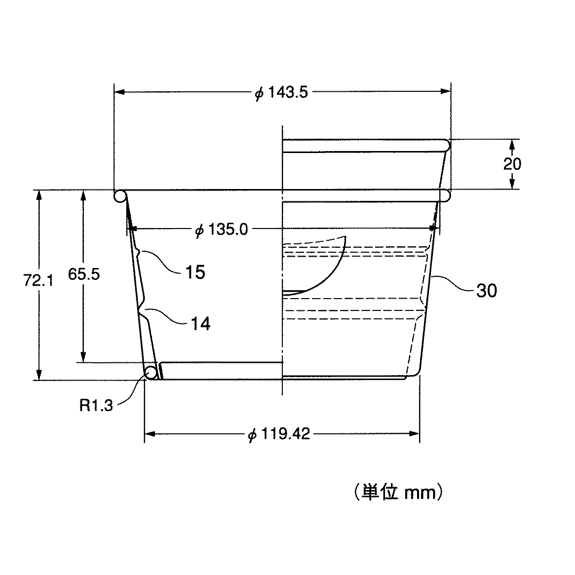
図5は、本発明によるつかみ片付き断熱容器の実施例サンプルの寸法図面である。
本発明によるつかみ片付き断熱容器30の実施例サンプルを次の仕様に従って作成した。また、つかみ片3が形成されない以外は全く同一仕様の比較例サンプルを用意した。
【0015】
本発明によるつかみ片付き断熱容器30は、以上の実施の態様の記載に限定されることなく、本発明の要旨を逸脱しない範囲内で種々の変形が可能である。
例えば、紙カップ本体20と筒状体10との間の断熱空間の形成は、筒状体10の内向きカールと水平リブ14とによることに限定されることはなく、紙カップ本体20の側壁11と筒状体10の側壁1間に断熱部材を介在させる方法によってもよい。ただし、つかみ片3の上部には自由空間のあることが望ましい。
【0016】
【発明の効果】
本発明によるつかみ片付き断熱容器30によれば、容器の外装となる筒状体10の側壁1の対向する位置に2枚のつかみ片3を設けることによって、内容量が大きく、形状が例えば丼型、鍋型であっても、熱湯調理、あるいは電子レンジ加熱調理後、熱さを余り感じないで、容易に持つことができるので、安全に、衛生的に食事の場に種々な調理食品を供し、楽しく、食べ易くさせることが可能となる。この効果は、特に高齢者や、身体障害者、子供等に対するバリアーフリー商品の提供を可能とするものである。
また、本発明による断熱容器30は、胴部外壁に凹凸がなく、印刷の自由度が高く、美しい、精細な印刷が可能であって、優れた印刷媒体となり、広口の容器の場合は、蓋材への印刷効果も相まって、店頭における優れた販促効果を発揮することができる。
また、本発明によるつかみ片付き断熱容器30の内面のポリオレフィン系樹脂層からは、これまでの断熱容器に使用されている発泡性ポリスチレンに見られる環境ホルモン等の疑惑物質の溶出がなく、衛生面で安心感を与えることができる。
さらに、つかみ片を設けることによるコスト上昇は殆どなく、合理的な経済コストで断熱容器を提供することができる。
さらにまた、本発明による断熱容器は、使用後は紙製品として廃棄され、また減容化が容易であるので廃棄処理性が良好であり、さらに、リサイクルも可能であるので、環境負荷の低減に貢献することができる。
【図面の簡単な説明】
【図1】本発明によるつかみ片付き断熱容器の全体構造の説明図
【図2】本発明によるつかみ片付き断熱容器の筒状体のブランク展開図
【図3】つかみ片のブランクにおける拡大説明図
【図4】本発明によるつかみ片付き断熱容器の使用時における状態説明図
【図5】本発明によるつかみ片付き断熱容器の実施例サンプルの寸法図面
【符号の説明】
1 筒状体の側壁
2 内向きカール
3 つかみ片
4 切れ目線
5 折線
5’ 小折線
6 繋ぎ部
7 切り欠き
8 底板
10 筒状体
10’ 筒状体のブランク
11 側壁
12 底板
13 外向きカール
14 外方向に突出する水平リブ
15 内方向に突出する水平リブ
20 紙カップ本体
30 本発明によるつかみ片付き断熱容器
C 内向きカール成形部
L 蓋材
N 胴貼り部
p1,p2 2点(折線の両端)[0001]
BACKGROUND OF THE INVENTION
The present invention relates to a paper insulated container used for instant foods that are poured by pouring hot water and cooked foods that are cooked in a microwave oven.
[0002]
[Prior art]
Up until now, paper insulation containers that have been used mainly for instant noodles have corrugated plate-like insulation processed so that ridges and recesses are alternately aligned in the vertical direction. Many are wound around the outer periphery of the body.
In Japanese Patent Application Laid-Open No. 8-113274, a heat insulating container in which the cross-sectional shape of the corrugated plate is changed to reduce the number of concave portions on the surface and the flat plate portion is increased is proposed and put into practical use.
In addition, Japanese Utility Model Laid-Open No. 4-45216 and Japanese Patent Laid-Open No. 8-104372 disclose a heat insulating container in which a liner or thin paper is further wound on a corrugated or embossed heat insulating material, and the surface has no irregularities. Proposed.
On the other hand, Japanese Utility Model Laid-Open No. 4-45212 also proposes a proposal to provide heat insulation by a space formed between double cups without using such a heat insulating material.
[0003]
[Problems to be solved by the invention]
As described above, various paper insulated containers have been proposed, and some of them have been put to practical use. However, most of the insulated containers are cup-shaped with a capacity of 750 cc or less when filled. Therefore, the body surface temperature immediately after cooking with hot water is considerably high, but the center of the body can be held with one hand.
However, if the shape becomes bowl-shaped and the internal capacity exceeds 800 cc, not only the diameter but also the weight will increase, so it can not be held with one hand, and it can be held from both sides with both hands to support the upper side wall of a heat-insulating container that tends to get hot. Therefore, there is a problem that the heat is felt strongly and there is a danger in carrying. In particular, in the case of cooking with a microwave oven, depending on the contents, it is heated to a very high temperature, and therefore the degree of danger when taking out from the microwave oven is high.
The present invention has been made in view of this problem, and even a large container heated to a high temperature can be safely and cleanly held by hand without feeling much heat, and at a low manufacturing cost. The purpose is to provide an insulated container.
[0004]
[Means for Solving the Problems]
The present invention is a heat-insulating container in which a bottomed paper cup body having an inner surface coated with a polyolefin-based resin and an outwardly curled portion formed on an upper opening edge is combined with a paper cylinder having an inverted frustoconical shape. The two side walls of the cylindrical body have a predetermined length and are separated by a fold line formed in a substantially circumferential direction of the side wall and a cut line connecting both ends of the fold line. A gripping piece that can be folded outward is formed by the fold line, and an inward curl that abuts against the barrel side wall of the paper cup body is provided at the bottom of the cylindrical body, and projects outwardly from the barrel side wall of the paper cup body A horizontal rib is provided, and a space is formed between the outer surface of the body side wall of the paper cup body and the inner surface of the cylindrical body by the inwardly curled and outwardly projecting horizontal rib, and this space allows the grip piece to be outward. When turning back, the side wall of the cylindrical body A gripping Katazuki insulated container characterized by deformed.
Further, the fold line is a straight line having a shortest distance connecting two points in the circumferential direction of the side wall, or is curved downward. Further, a connecting portion that can be easily separated is formed in the middle of the cut line, and a notch is provided in a part of the periphery of the grip piece, or a tip portion of the grip piece can be folded back. It is. Furthermore, both ends of the cut line end in a round shape.
[0005]
DETAILED DESCRIPTION OF THE INVENTION
The present invention will be described in more detail with reference to the drawings.
FIG. 1 is an explanatory view of the overall structure of a heat insulating container with a gripping piece according to the present invention.
FIG. 1 is a sectional view and a side view showing an embodiment of a
A
Formation of the heat insulating space of the
The main role of the
[0006]
FIG. 2 is a blank development view of a cylindrical body of a heat insulating container with a gripping piece according to the present invention.
As shown in FIG. 2, the blank 10 ′ of the
The cylindrical body blank 10 ′ is formed by bonding the cylinder pasting portions N together to form an inverted truncated cone-shaped
The
[0007]
FIG. 3 is an enlarged explanatory diagram of a grip piece blank.
FIG. 3 (a) shows an embodiment of the
A connecting
The connecting
Further, a
FIG. 3B shows another embodiment of the grip piece. Instead of providing the
Furthermore, it is preferable to draw a round at the end of the cut line 4 as shown in FIG. This is to prevent the end portion of the cut line 4 from being easily split upward from the extreme ends p1 and p2 because the end portion of the cut line 4 approaches parallel to the paper.
Since all of the
Further, most of the area of the blank 10 ′ is printed before the blank 10 ′ is processed and functions as an information medium. However, the printing effect or design effect is greatly hindered by the processing of the
[0008]
FIG. 4 is an explanatory diagram of the state of the insulated container with a gripping piece according to the present invention in use.
Fig.4 (a) is a side view which shows the state by which the
As shown in FIG. 1, the
However, in the case of the
When the
[0009]
FIG.4 (b) is a perspective view which shows the state just before the cooking of the
The
In the case of hot water cooking and heating, the lid L is temporarily opened and hot water is supplied, and then the lid L is closed again and left for 3 to 4 minutes. In the case of microwave cooking, the lid L is slightly opened. What is necessary is just to heat-cook in a state.
After cooking, by holding the
In the case of a normal bowl-shaped container, there is a case where the finger is placed on the edge of the container to carry it, and there is a problem in hygiene. However, the carrying by the
Note that the
[0010]
In the
As the paperboard material used for forming the
Usually, the inner surface of the cup base paper is formed by extrusion coating a polyolefin resin layer such as low density polyethylene resin, medium density polyethylene resin, high density polyethylene resin, linear low density polyethylene resin in the range of 20 to 80 μm. .
This polyolefin-based resin layer improves the cup formability at the bottom, curl, and body pasting part, in addition to preventing the contents from penetrating into the paperboard and improving the contents protection suitability. The effect of improving the sealing property by heat sealing in the top curl portion is also brought about.
The basis weight of the cup base paper is about 190 to 450 g / m 2 .
On the other hand, cardboard of a basis weight of 230 to 450 g / m 2 or a coated ball type can be used for forming the
As for the surface processing of the
Therefore, the following laminated structure can be given in order from the surface.
PET12 μm / PE15 μm / paper 270 g / m 2 / PE15 μm
Moreover, you may use the water-resistant double-sided coated ball which gave water resistance at the papermaking stage.
[0011]
Since the surface of the
[0012]
In general, when hot water comes into contact with the plastic surface or plastic layer on the inner surface of the container, it is important to consider monomers remaining in the plastic, heavy metals used in the polymerization catalyst, other additives, etc. This is a problem of food contamination due to elution. In this case, it is natural that the amount of these elutions does not exceed the standard value stipulated by the Food Sanitation Law. However, even if the amount is less than this value, it is frequently used for, for example, baby bottles and school meals. Dissolves bisphenol A, which is eluted from polycarbonate resin, and environmental hormones (exogenous endocrine disrupting chemicals) that have been pointed out to be likely to disturb the endocrine activity of organisms, such as styrene oligomers, which are eluted from expanded polystyrene containers. It is desirable to avoid the use of resins to prevent from the precautionary principle.
In the
[0013]
Next, the manufacturing method of the
First, a laminated sheet mainly made of a paperboard for a
A cup-forming machine is used to form an inverted
The processing method of the
In this case, the
The
The inwardly projecting
On the other hand, a
Finally, if the
The completed
[0014]
【Example】
FIG. 5 is a dimensional drawing of an example sample of the insulated container with a gripping piece according to the present invention.
An example sample of the
[0015]
The
For example, the formation of the heat insulating space between the
[0016]
【The invention's effect】
According to the
Further, the
In addition, from the polyolefin resin layer on the inner surface of the
Furthermore, there is almost no increase in cost due to the provision of the gripping piece, and the insulated container can be provided at a reasonable economic cost.
Furthermore, the heat-insulated container according to the present invention is discarded as a paper product after use and is easy to reduce in volume, so that the disposal property is good and can be recycled. Can contribute.
[Brief description of the drawings]
FIG. 1 is an explanatory view of the overall structure of a heat insulating container with a gripping piece according to the present invention. FIG. 2 is a blank development view of a cylindrical body of a heat insulating container with a gripping piece according to the present invention. 4] State explanatory drawing at the time of use of the insulated container with a gripping piece according to the present invention. [FIG. 5] Dimensional drawing of an example sample of the insulated container with a gripping piece according to the present invention.
DESCRIPTION OF
p1, p2 2 points (both ends of broken line)
Claims (7)
Priority Applications (24)
| Application Number | Priority Date | Filing Date | Title |
|---|---|---|---|
| JP10206799A JP4360708B2 (en) | 1998-11-20 | 1999-04-09 | Insulated container with gripping piece |
| KR1020007013838A KR20010034903A (en) | 1998-09-18 | 1999-09-17 | Insulating container |
| KR1020007013839A KR20010034904A (en) | 1998-09-18 | 1999-09-17 | Container |
| KR1020097016544A KR100932327B1 (en) | 1998-09-18 | 1999-09-17 | Method for producing heat-insulating paper container |
| KR1020007013836A KR20010034902A (en) | 1998-09-18 | 1999-09-17 | Insulating container |
| KR1020077016027A KR20070087653A (en) | 1998-09-18 | 1999-09-17 | Container |
| CN2006101006388A CN101028874B (en) | 1998-09-18 | 1999-09-17 | Paper heat insulation container and manufacturing method for paper container |
| KR1020007013840A KR100867779B1 (en) | 1998-09-18 | 1999-09-17 | Device and method used for manufacturing containers |
| SG200701492-1A SG152919A1 (en) | 1998-09-18 | 1999-09-17 | Apparatus for manufacture of heat insulating container |
| KR1020007013834A KR20010034900A (en) | 1998-09-18 | 1999-09-17 | Insulating container |
| TW088116057A TW501996B (en) | 1998-09-18 | 1999-09-17 | Container, heat insulating container, heat insulating container with grippers, heat insulating container sleeve preparing apparatus, blank supplying apparatus and sleeve ejecting apparatus for sleeve preparing apparatus heat insulating container |
| PCT/JP1999/005076 WO2000017058A1 (en) | 1998-09-18 | 1999-09-17 | Container, insulating container, and devices and method used for manufacturing these containers |
| KR1020007013835A KR20010034901A (en) | 1998-09-18 | 1999-09-17 | Insulating container |
| KR1020077016022A KR100891582B1 (en) | 1998-09-18 | 1999-09-17 | Container |
| KR1020007013832A KR20010034898A (en) | 1998-09-18 | 1999-09-17 | Insulating container |
| KR1020007013833A KR100730682B1 (en) | 1998-09-18 | 1999-09-17 | Insulating container |
| SG200205253A SG117419A1 (en) | 1998-09-18 | 1999-09-17 | Apparatus for manufacture of heat insulating container |
| KR1020077005384A KR20070032831A (en) | 1998-09-18 | 1999-09-17 | Insulating container |
| CN99802162A CN1128744C (en) | 1998-09-18 | 1999-09-17 | Container, insulating container, and device and method used for mfg. these container |
| KR1020007013837A KR100324646B1 (en) | 1998-09-18 | 1999-09-17 | Insulating container |
| KR1020007005370A KR100306360B1 (en) | 1998-09-18 | 2000-05-17 | Insulating container |
| HK01105322A HK1034700A1 (en) | 1998-09-18 | 2001-07-31 | Container, insulating container, and devices and method used for manufacturing these containers |
| HK07102315.7A HK1096643A1 (en) | 1998-09-18 | 2007-03-01 | Heat insulating container and producing apparatus for manufacturing heat insulating container |
| HK07107245.1A HK1103288A1 (en) | 1998-09-18 | 2007-07-06 | Paper adiabatic container |
Applications Claiming Priority (3)
| Application Number | Priority Date | Filing Date | Title |
|---|---|---|---|
| JP33030398 | 1998-11-20 | ||
| JP10-330303 | 1998-11-20 | ||
| JP10206799A JP4360708B2 (en) | 1998-11-20 | 1999-04-09 | Insulated container with gripping piece |
Publications (2)
| Publication Number | Publication Date |
|---|---|
| JP2000211650A JP2000211650A (en) | 2000-08-02 |
| JP4360708B2 true JP4360708B2 (en) | 2009-11-11 |
Family
ID=26442808
Family Applications (1)
| Application Number | Title | Priority Date | Filing Date |
|---|---|---|---|
| JP10206799A Expired - Fee Related JP4360708B2 (en) | 1998-09-18 | 1999-04-09 | Insulated container with gripping piece |
Country Status (1)
| Country | Link |
|---|---|
| JP (1) | JP4360708B2 (en) |
Families Citing this family (5)
| Publication number | Priority date | Publication date | Assignee | Title |
|---|---|---|---|---|
| DE202014008489U1 (en) * | 2014-10-27 | 2016-01-28 | Va-Q-Tec Ag | Box-shaped transport container |
| JP7021521B2 (en) * | 2017-12-11 | 2022-02-17 | 大日本印刷株式会社 | Grip container and grip piece |
| JP7021522B2 (en) * | 2017-12-11 | 2022-02-17 | 大日本印刷株式会社 | Grip container and grip piece |
| JP7168434B2 (en) * | 2018-12-07 | 2022-11-09 | 東罐興業株式会社 | Paper lid and paper lid manufacturing method |
| KR102518325B1 (en) * | 2020-08-31 | 2023-04-05 | 현진제업주식회사 | Disposable paper container and method for manufacturing the same |
-
1999
- 1999-04-09 JP JP10206799A patent/JP4360708B2/en not_active Expired - Fee Related
Also Published As
| Publication number | Publication date |
|---|---|
| JP2000211650A (en) | 2000-08-02 |
Similar Documents
| Publication | Publication Date | Title |
|---|---|---|
| KR100829673B1 (en) | Insulating container | |
| JP2000085852A (en) | Heat insulating container | |
| MXPA06012135A (en) | Insulating cup wrapper and insulated container formed with wrapper. | |
| WO2011056398A1 (en) | Air pocket insulated disposable plastic cup | |
| JP2023525843A (en) | Cup with integrated folding lid | |
| JP3908384B2 (en) | Insulated container | |
| JP4360708B2 (en) | Insulated container with gripping piece | |
| WO2006095730A1 (en) | Heat insulation container | |
| JP4043815B2 (en) | Insulated container with hidden picture | |
| JP4294579B2 (en) | Insulated container | |
| JP3953583B2 (en) | Exterior of microwave oven cooking container | |
| JP2001002052A (en) | Heat insulating paper cup | |
| JP2001031152A (en) | Heat insulation container | |
| JP3967129B2 (en) | Insulated paper container | |
| JPH11342982A (en) | Heat insulating container with handle | |
| JP2012091808A (en) | Paper container in shape of bowl | |
| JP4422237B2 (en) | Insulated container | |
| JP2000118590A (en) | Ice cream container | |
| JP4791177B2 (en) | Insulating paper container | |
| JP3195580U (en) | Structure of packaging container with cardboard jacket | |
| JPH11130157A (en) | Heat-insulating container | |
| JP2000177724A (en) | Heat-insulating paper cup | |
| CN216316902U (en) | Paper bowl capable of entering microwave oven | |
| EP2994396B1 (en) | Pop-out constructible utensil | |
| JPH0327963Y2 (en) |
Legal Events
| Date | Code | Title | Description |
|---|---|---|---|
| RD03 | Notification of appointment of power of attorney |
Free format text: JAPANESE INTERMEDIATE CODE: A7423 Effective date: 20051012 |
|
| A621 | Written request for application examination |
Free format text: JAPANESE INTERMEDIATE CODE: A621 Effective date: 20060317 |
|
| A131 | Notification of reasons for refusal |
Free format text: JAPANESE INTERMEDIATE CODE: A131 Effective date: 20090515 |
|
| A521 | Written amendment |
Free format text: JAPANESE INTERMEDIATE CODE: A523 Effective date: 20090710 |
|
| TRDD | Decision of grant or rejection written | ||
| A01 | Written decision to grant a patent or to grant a registration (utility model) |
Free format text: JAPANESE INTERMEDIATE CODE: A01 Effective date: 20090804 |
|
| A01 | Written decision to grant a patent or to grant a registration (utility model) |
Free format text: JAPANESE INTERMEDIATE CODE: A01 |
|
| A61 | First payment of annual fees (during grant procedure) |
Free format text: JAPANESE INTERMEDIATE CODE: A61 Effective date: 20090811 |
|
| R150 | Certificate of patent or registration of utility model |
Free format text: JAPANESE INTERMEDIATE CODE: R150 |
|
| FPAY | Renewal fee payment (event date is renewal date of database) |
Free format text: PAYMENT UNTIL: 20120821 Year of fee payment: 3 |
|
| FPAY | Renewal fee payment (event date is renewal date of database) |
Free format text: PAYMENT UNTIL: 20120821 Year of fee payment: 3 |
|
| FPAY | Renewal fee payment (event date is renewal date of database) |
Free format text: PAYMENT UNTIL: 20130821 Year of fee payment: 4 |
|
| LAPS | Cancellation because of no payment of annual fees |