JP4358084B2 - Foldable portable radio - Google Patents
Foldable portable radio Download PDFInfo
- Publication number
- JP4358084B2 JP4358084B2 JP2004324136A JP2004324136A JP4358084B2 JP 4358084 B2 JP4358084 B2 JP 4358084B2 JP 2004324136 A JP2004324136 A JP 2004324136A JP 2004324136 A JP2004324136 A JP 2004324136A JP 4358084 B2 JP4358084 B2 JP 4358084B2
- Authority
- JP
- Japan
- Prior art keywords
- conductor
- casing
- antenna
- housing
- power feeding
- Prior art date
- Legal status (The legal status is an assumption and is not a legal conclusion. Google has not performed a legal analysis and makes no representation as to the accuracy of the status listed.)
- Expired - Fee Related
Links
Images


Classifications
-
- H—ELECTRICITY
- H01—ELECTRIC ELEMENTS
- H01Q—ANTENNAS, i.e. RADIO AERIALS
- H01Q1/00—Details of, or arrangements associated with, antennas
- H01Q1/12—Supports; Mounting means
- H01Q1/22—Supports; Mounting means by structural association with other equipment or articles
- H01Q1/24—Supports; Mounting means by structural association with other equipment or articles with receiving set
- H01Q1/241—Supports; Mounting means by structural association with other equipment or articles with receiving set used in mobile communications, e.g. GSM
- H01Q1/242—Supports; Mounting means by structural association with other equipment or articles with receiving set used in mobile communications, e.g. GSM specially adapted for hand-held use
- H01Q1/243—Supports; Mounting means by structural association with other equipment or articles with receiving set used in mobile communications, e.g. GSM specially adapted for hand-held use with built-in antennas
-
- H—ELECTRICITY
- H01—ELECTRIC ELEMENTS
- H01Q—ANTENNAS, i.e. RADIO AERIALS
- H01Q9/00—Electrically-short antennas having dimensions not more than twice the operating wavelength and consisting of conductive active radiating elements
- H01Q9/04—Resonant antennas
- H01Q9/16—Resonant antennas with feed intermediate between the extremities of the antenna, e.g. centre-fed dipole
- H01Q9/28—Conical, cylindrical, cage, strip, gauze, or like elements having an extended radiating surface; Elements comprising two conical surfaces having collinear axes and adjacent apices and fed by two-conductor transmission lines
- H01Q9/285—Planar dipole
-
- H—ELECTRICITY
- H01—ELECTRIC ELEMENTS
- H01Q—ANTENNAS, i.e. RADIO AERIALS
- H01Q9/00—Electrically-short antennas having dimensions not more than twice the operating wavelength and consisting of conductive active radiating elements
- H01Q9/04—Resonant antennas
- H01Q9/30—Resonant antennas with feed to end of elongated active element, e.g. unipole
- H01Q9/42—Resonant antennas with feed to end of elongated active element, e.g. unipole with folded element, the folded parts being spaced apart a small fraction of the operating wavelength
-
- H—ELECTRICITY
- H04—ELECTRIC COMMUNICATION TECHNIQUE
- H04M—TELEPHONIC COMMUNICATION
- H04M1/00—Substation equipment, e.g. for use by subscribers
- H04M1/02—Constructional features of telephone sets
- H04M1/0202—Portable telephone sets, e.g. cordless phones, mobile phones or bar type handsets
- H04M1/0206—Portable telephones comprising a plurality of mechanically joined movable body parts, e.g. hinged housings
- H04M1/0208—Portable telephones comprising a plurality of mechanically joined movable body parts, e.g. hinged housings characterized by the relative motions of the body parts
- H04M1/0214—Foldable telephones, i.e. with body parts pivoting to an open position around an axis parallel to the plane they define in closed position
- H04M1/0216—Foldable in one direction, i.e. using a one degree of freedom hinge
Landscapes
- Engineering & Computer Science (AREA)
- Computer Networks & Wireless Communication (AREA)
- Support Of Aerials (AREA)
- Telephone Set Structure (AREA)
- Details Of Aerials (AREA)
- Transceivers (AREA)
Description
本発明は、高いアンテナ性能を有する小型の折畳式携帯無線機に関するものである。 The present invention relates to a small foldable portable radio having high antenna performance.
近年、携帯無線機の一種である携帯電話機が広く普及しているが、この携帯電話機には、各種さまざまなタイプのものが開発されている。その中でも、使用しないときには上下の筐体を折畳んで携帯性を高めたコンパクトな折畳式のものが広く用いられている。このように使用状態により、その形態を変えることができる構造を持つため、そのそれぞれの状態におけるアンテナ性能の確保が重要である。また、この折畳式携帯無線機においても小型化と多機能化が進んでおり、近年の多機能化のひとつとして、デザイン性向上のためアンテナの内蔵化が進んでいる。 In recent years, mobile phones, which are a type of portable radio device, have become widespread, and various types of mobile phones have been developed. Among them, when not in use, a compact folding type in which the upper and lower cases are folded to improve portability is widely used. As described above, since the structure can be changed depending on the use state, it is important to secure the antenna performance in each state. In addition, miniaturization and multi-functionalization are also advancing in this foldable portable wireless device. As one of the multi-functionalizations in recent years, antennas are being built in to improve design.
一般に、折畳式携帯電話において、開き閉じ共に、良好なアンテナ性能を得る手段として以下に三つの例を示す。 In general, in a foldable mobile phone, three examples are shown below as means for obtaining good antenna performance in both opening and closing.
一つ目の例は下筐体のヒンジ側に突起型のアンテナを搭載した折畳式携帯無線機である。この突起型アンテナは、一般にヘリカルアンテナや伸縮式モノポールアンテナが用いられており、開いた状態ではアンテナが上筐体の回路基板上の接地電位をもつ導体パターンであるグランドパターンを励振させる共振素子となり、上筐体の回路基板上のグランドパターンと下筐体の回路基板上のグランドパターンを放射素子とするダイポールアンテナとして動作し、アンテナ部が筐体から突起しているので、携帯電話機を手で保持した状態のアンテナ利得を高くできるといった利点がある。また閉じた場合はヘリカルアンテナ等の放射素子により波長を短縮し、λ/4系のモノポールアンテナとして動作する。 The first example is a foldable portable wireless device in which a protruding antenna is mounted on the hinge side of the lower housing. In general, a helical antenna or a telescopic monopole antenna is used for this protruding antenna, and in an open state, the antenna excites a ground pattern which is a conductor pattern having a ground potential on the circuit board of the upper casing. It operates as a dipole antenna using the ground pattern on the circuit board of the upper casing and the ground pattern on the circuit board of the lower casing as a radiating element, and the antenna part protrudes from the casing. There is an advantage that the antenna gain in the state held by can be increased. When closed, the wavelength is shortened by a radiating element such as a helical antenna, and the antenna operates as a λ / 4 monopole antenna.
しかし、上述の構成はアンテナの突起部が携帯無線機としての概観を損ねることになり、近年のアンテナ内蔵化に反する。また、ホイップアンテナは筐体内に収納するスペースを必要とし、携帯無線機の小型化、薄型化の妨げになる。また、アンテナ部が筐体から突起しているので、携帯電話機を手で保持した状態のアンテナ利得を高くできるといった利点があるが、放射素子として、アンテナ部に電流が集中するため、通話時に手や顔による影響が大きく、通話時特性の変動が大きくなってしまう。 However, in the above configuration, the protruding portion of the antenna impairs the appearance as a portable wireless device, which is contrary to the recent built-in antenna. In addition, the whip antenna requires a space to be accommodated in the housing, which hinders the miniaturization and thinning of the portable wireless device. In addition, since the antenna portion protrudes from the housing, there is an advantage that the antenna gain in a state where the mobile phone is held by hand can be increased. The effect of the face and the face is large, and the fluctuation of the characteristics during the call becomes large.
二つ目の例として、突起部をなくしアンテナを内蔵した構成として、L字アンテナや逆Fアンテナなどがあり、これらのアンテナは筐体内部に完全に内蔵した形で動作する。下筐体ヒンジ側にL字アンテナを構成した場合、ヘリカルアンテナを用いた場合と同様に上筐体を励振させる共振素子として動作するが、内蔵するモノポールアンテナとしての長さに限界があるため、開き時に上筐体との電気的結合が弱く開き時の特性が劣る。また、上筐体に逆Fアンテナを構成する場合、その特性を確保するには、上筐体内の基板との高さを取る必要があり、またその板状アンテナの面積も広くする必要があり、携帯無線機の小型化、薄型化の妨げとなる。 As a second example, there is an L-shaped antenna, an inverted F antenna, or the like as a configuration in which the protrusion is eliminated and the antenna is built in. These antennas operate in a form that is completely built in the housing. When an L-shaped antenna is configured on the lower casing hinge side, it operates as a resonant element that excites the upper casing in the same manner as when using a helical antenna, but there is a limit to the length of a built-in monopole antenna. When opened, the electrical connection with the upper casing is weak, and the characteristics when opened are inferior. In addition, when an inverted F antenna is configured in the upper housing, it is necessary to take a height with the substrate in the upper housing in order to ensure the characteristics, and it is also necessary to increase the area of the plate antenna. This hinders the miniaturization and thinning of portable wireless devices.
三つ目の例として、一つ目の例としてあげた、開き時に上筐体内の導体を放射素子として用いる原理を応用する事で、突起物のないアンテナ構成として、上筐体内の導体を開き時に直接励振し、放射素子として用いる方法がある。例えば特許文献1に開示されているような、上部ケース内のシールドボックスにフレキシブルケーブルで接続し上部シールドボックスをアンテナとして使用する構造を備えた折畳み式無線機がある。この方法は放射する筐体に高さといった制限もなく、アンテナの実効面積を広くとる事が可能となるため、広帯域、高利得なアンテナ性能を得る事ができる。
As a third example, by applying the principle of using the conductor in the upper casing as a radiating element when opened, the conductor in the upper casing is opened as an antenna configuration without protrusions. Sometimes there is a method of directly exciting and using as a radiating element. For example, there is a foldable radio device having a structure in which a flexible cable is connected to a shield box in an upper case and the upper shield box is used as an antenna as disclosed in
しかし、このアンテナ構成は開き時には理想的なλ/2系のダイポールアンテナとして
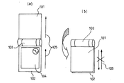
動作するが、閉じ時はその電流の流れが互いに打ち消し合い、原理的に動作しない。上筐体101と下筐体102が開閉ヒンジ103により接続されたモデルにおいて、図1(a)に示されているように、その電流の流れ105は開き時にダイポールアンテナとして動作するが、図1(b)に示されているように、閉じ時はその電流の流れ105が打ち消し合い放射抵抗が低下する。図2はこうしたアンテナ性能の変化を示したものである。この比較実験では、使用周波数を900MHz帯とし、横軸に周波数(MHz)、縦軸にVSWR(Voltage Standing Wave Ratio:電圧定在波比)とした。この図2において、開き状態のアンテナ特性(VSWR)の変化を示すグラフをα、閉じ状態アンテナ特性(VSWR)の変化を示すグラフをβで示している。この図2に示す実験結果から分かるように、良好なアンテナ特性を得るための要件の一つであるVSWR<3(反射波の電圧が50%以下となる)を満たす周波数帯域の幅について開き状態は350MHz以上の広さを有するが、閉じの状態ではVSWR<3の周波数帯が存在せず、大幅な特性の変化を確認する事ができる。よって、閉じ時に動作する別のアンテナを必要とし、その回路構成が複雑になる。
However, this antenna configuration operates as an ideal λ / 2-type dipole antenna when opened, but when closed, the current flows cancel each other and do not operate in principle. In the model in which the
上述の問題は、折畳式携帯電話に限られず、一般の折畳式携帯無線機についても生じ得る。 The above-mentioned problem is not limited to a folding mobile phone, but can also occur for a general folding portable radio.
上述したように、小型の折り畳み携帯無線機において、広帯域、高利得を目的とし、開き時に上筐体内の導体を直接励振させアンテナとして用いた場合には、閉じ時は大幅に利得が劣化するおそれがある。 As described above, in a small folding portable radio device, if the purpose is wide bandwidth and high gain, and the conductor in the upper housing is directly excited and used as an antenna when opened, the gain may be greatly degraded when closed. There is.
本発明は、一つのアンテナで、大きなスペースを必要とせず、開閉共に高いアンテナ性能を発揮し、小型化に好適な折畳式携帯無線機を提供する事を目的とする。 SUMMARY OF THE INVENTION An object of the present invention is to provide a foldable portable radio device that is suitable for downsizing, with a single antenna that does not require a large space and exhibits high antenna performance in both opening and closing.
本発明の折畳式携帯無線機は、第一の筐体と、第二の筐体と、第一の筐体と第二の筐体を開閉可能に接続する連結部と、第一の筐体に配置された導体素子と、第二の筐体に配置された給電素子とを備える。そして、(A)連結部による開き状態においては、導体素子と給電素子が互いに近接して給電時に電磁的結合可能であり、(B)連結部による閉じ状態においては、導体素子と給電素子が、(A)の状態よりも距離的に離れ、給電時に電磁的結合されない。尚、「給電時の電磁的結合」とは、近接した二つの導体の電磁的結合及び二つの導体の直接接触(直列的接続)による電磁的結合の双方を少なくとも含み得る。
給電素子を、略4分の1波長の電気長を有するよう、構成することができる。
The foldable portable wireless device of the present invention includes a first casing, a second casing, a connecting portion that connects the first casing and the second casing so as to be openable and closable, and a first casing. A conductor element disposed on the body; and a power feeding element disposed on the second housing. (A) In the open state by the connecting portion, the conductor element and the feeding element are close to each other and can be electromagnetically coupled at the time of power feeding, and (B) in the closed state by the connecting portion, the conductor element and the feeding element are It is farther away than the state of (A), and is not electromagnetically coupled during power feeding. The “electromagnetic coupling at the time of feeding” can include at least both electromagnetic coupling of two adjacent conductors and electromagnetic coupling by direct contact (series connection) of the two conductors.
The feed element can be configured to have an electrical length of approximately a quarter wavelength.
導体素子を、第一の筐体内に配置された導体板に接続されるよう、構成することができる。 The conductor element can be configured to be connected to a conductor plate disposed in the first housing.
導体素子は第一の筐体に取り付けられた導体カバーにより代用する事も可能であり、導体カバーを第一の筐体に配置された導体板に少なくとも一つの接点を介して接続する構成としてもよい。 The conductor element can be substituted by a conductor cover attached to the first casing, and the conductor cover may be connected to the conductor plate disposed in the first casing via at least one contact. Good.
導体素子及び給電素子各々に平面部を設け、上記(A)の状態において各平面が近接して対向するよう構成してもよい。 A planar portion may be provided for each of the conductor element and the feeding element, and the respective planes may be close to each other and face each other in the state (A).
導体素子を、第一の筐体の連結部に隣接した端部に配置し、給電素子を、第二の筐体の連結部に隣接した端部に配置し、上記(A)の状態においては、導体素子及び給電素子は、連結部に隣接して互いに対向して配置され、上記(B)の状態においては、導体素子及び給電素子は、連結部を隔てて配置されるよう、構成してもよい。
導体素子及び給電素子の主要部が、連結部の回転軸に略平行となるよう、構成してもよい。
導体素子が、略4分の1波長の電気長を有するよう、構成してもよい。
導体素子の一端が第一の筐体に配置された導体板または第一の筐体に取り付けられた導体カバーに接続され、他端が開放端であるよう、構成してもよい。
導体素子の一端と、第一の筐体に配置された導体板または第一の筐体に取り付けられた導体カバーとの接続位置が、給電素子の給電部近傍であるよう、構成してもよい。
第一の筐体の内部に配置された回路部品と第二の筐体の内部に配置された回路部品とを電気的に接続する複数の導電線からなる配線束を備え、配線束を給電素子の給電部から所定の間隔を隔てて配置するよう、構成してもよい。
In the state of (A), the conductor element is disposed at the end adjacent to the connecting portion of the first housing, the power feeding element is disposed at the end adjacent to the connecting portion of the second housing. The conductor element and the power feeding element are disposed adjacent to each other adjacent to the connecting portion, and in the state (B), the conductor element and the power feeding element are configured so as to be disposed across the connecting portion. Also good.
You may comprise so that the principal part of a conductor element and a feed element may become substantially parallel to the rotating shaft of a connection part.
The conductor element may be configured to have an electrical length of approximately a quarter wavelength.
You may comprise so that one end of a conductor element may be connected to the conductor board arrange | positioned at the 1st housing | casing or the conductor cover attached to the 1st housing | casing, and the other end may be an open end.
You may comprise so that the connection position of the end of a conductor element and the conductor plate arrange | positioned at the 1st housing | casing or the conductor cover attached to the 1st housing | casing may be the electric power feeding part vicinity of a power feeding element. .
A wiring bundle comprising a plurality of conductive wires for electrically connecting a circuit component arranged inside the first housing and a circuit component arranged inside the second housing, the wiring bundle being a feeding element You may comprise so that it may arrange | position at predetermined intervals from the electric power feeding part.
上記(A)の状態において、導体素子と、給電素子が接触するよう構成してもよい。 In the state (A), the conductor element and the power feeding element may be in contact with each other.
導体素子が、第一の筐体に形成された導通孔から露出し、給電素子がピン状に形成され第二の筐体から突出した接点部を有し、上記(A)の状態において、導体素子が接点部に直接接触するよう構成してもよい。
導体素子または給電素子の少なくとも一方を、電気長の異なる複数の素子で構成してもよい。
導体素子の一端を、第一の筐体に配置された導体板または第一の筐体に取り付けられた導体カバーに接続するか開放とするかを切り換える第一切換部と、導体素子の他端を、第一の筐体に配置された導体板または第一の筐体に取り付けられた導体カバーに接続するか開放とするかを切り換える第二切換部とを備えるよう構成してもよい。
The conductor element is exposed from a conduction hole formed in the first casing, and the power feeding element is formed in a pin shape and has a contact portion protruding from the second casing. You may comprise so that an element may contact a contact part directly.
At least one of the conductor element and the feeding element may be composed of a plurality of elements having different electrical lengths.
A first switching section for switching whether one end of the conductor element is connected to a conductor plate disposed in the first casing or a conductor cover attached to the first casing, or the other end of the conductor element; May be configured to include a second switching unit that switches between connection to an open conductor plate disposed in the first housing or a conductor cover attached to the first housing.
本発明の携帯無線機は、第一の筐体を上筐体とし、第二の筐体を下筐体とした折畳式携帯電話に利用することが可能である。 The portable wireless device of the present invention can be used for a foldable mobile phone having a first casing as an upper casing and a second casing as a lower casing.
本発明によれば、一つのアンテナで、大きなスペースを必要とせず、開閉共に高いアンテナ性能を発揮し、小型化に好適な折畳式携帯無線機を提供する事ができる。 According to the present invention, it is possible to provide a foldable portable wireless device that does not require a large space with one antenna, exhibits high antenna performance in both opening and closing, and is suitable for downsizing.
以下、本発明の実施形態について、添付図面を参照しながら詳細に説明する。 Hereinafter, embodiments of the present invention will be described in detail with reference to the accompanying drawings.
(第1実施形態)
図3は本発明の実施形態に係る折畳式携帯無線機を示すものであり、折畳式携帯電話に応用した例を示す。この折畳式携帯電話は、第一の筐体を構成する上筐体301及び第二の筐体を構成する下筐体302が、連結部を構成するヒンジ部303を介して連結されており、ヒンジ部303を中心として回動することにより開いた状態と閉じた状態の2つの状態を取り得る。
(First embodiment)
FIG. 3 shows a foldable portable radio apparatus according to an embodiment of the present invention, and shows an example applied to a foldable portable telephone. In this foldable mobile phone, an
上筐体301には、液晶表示部(LCD)306および図示外の受話部(スピーカ)などを設けているほか、上基板(第一の基板)304などを内部に配置しており、背面側に上基板304と接続された、導体素子を構成する板状導体素子308を配置している。板状導体素子308は、上筐体301のヒンジ部303寄りの一端部に配置されている。
The
一方、下筐体302には、操作部及び図示外の送話部(マイク)などを設けているほか、下基板(第二の基板)305を内部に配置している。この下基板305には、図示外の制御回路を含む各種の回路、例えば後述する整合回路309及び無線部310などが実装されている。
On the other hand, the
さらに、下筐体302にはヒンジ部303寄りの一端部に、給電素子を構成する給電板金307を備え、開き時には、上基板304と接続された、板状導体素子308とお互いの平面同士で近接対向する。閉じ時には、板状導体素子308は、下筐体302から見てヒンジ部303の上側部に存在することとなり、給電板金307から引き離される。この給電板金307の一端部は、整合回路309を介して無線部310に接続されている。
Further, the
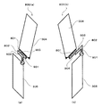
図4(a)に示すように、この給電板金307は、下筐体上部に存在するため、開き時は構造的に上筐体301に近接する位置に存在する。そして、板状導体素子308と給電板金307は、ヒンジ部303に隣接した位置で、互いに対向近接し、給電時に容量結合され得る。さらに、その形状が板状である、上基板グランドに接続された板状導体素子308と給電板金307は、面的に近接する。すなわち、板状導体素子308と給電板金307各々の平面部が、近接して対向する。平面部の対向は、容量を持ちコンデンサとして置きかえる事ができ、高周波領域では低インピーダンスとなり、導通状態401と考える事ができる。これにより、上筐体内の導体が上側のアンテナ素子として動作し、そのインピーダンスを無線回路310の入力インピーダンスに整合する機能を整合回路309が果たし、下基板305上のグランドパターンが下側のアンテナ素子として動作する。すなわち、上筐体301のグランドパターンと下基板305上のグランドパターンとがダイポールアンテナとして動作するため、直接上筐体を励振したアンテナ構成と同等の特性を得る事ができる。
As shown in FIG. 4A, the power
一方、図4(b)に示されているように、閉じ時には板状導体素子308が、給電板金307から引き離されるため、高周波領域での容量結合401は消失する。すなわち、閉じ状態においては、板状導体素子308と給電板金307は開き状態状態よりも距離的に離れ、通電時においても電気的に結合されない。本例では、板状導体素子308と給電板金307は、ヒンジ部303を隔てて配置される。この結果、図1(b)に示されているような、電流の流れ105の打ち消し合いが起こることはなく、給電板金307が、λ/
4系のモノポールアンテナとして動作し、良好なアンテナ性能が確保される。
On the other hand, as shown in FIG. 4B, since the plate-
It operates as a 4-system monopole antenna, ensuring good antenna performance.
また、閉じ時には給電板金307がその下基板305との高さ(図3におけるh)を調節する事で、L字型を有するL字アンテナとして動作し、エレメント長が短くとも、板状に折り曲げ実効面積を大きくとる事で、その周りを包む樹脂材等の波長短縮効果により、共振周波数を下げる事ができる。図6に本構造と従来構造による閉じ時のアンテナ性能の比較を示す。この比較実験では、使用周波数を900MHzとし、横軸に周波数(MHz)、縦軸にVSWR(Voltage Standing Wave Ratio:電圧定在波比)とした。この図6において、従来構造の閉じ時のアンテナ特性(VSWR)の変化を示すグラフをβ、本提案による構造の閉じ時のアンテナ特性(VSWR)の変化を示すグラフをγで示している。この図6に示す実験結果から分かるように、VSWR<3を満たす周波数帯域の幅について従来構造の閉じ状態では存在せず、本提案によるアンテナ構造により140MHzの帯域を得る事ができた。
When the power
また、上筐体301の板状導体素子308と、下筐体302の給電板金307は、開き時に、容量結合するため、板状導体素子308のサイズは大きくすることも可能である。図5はそのような変形の具体例を示す。上筐体301の背面側のケース501(導体カバー)を金属にて形成し、板状導体素子308として使用した。この場合、背面側ケース501は、上基板グランドと同じ電流の流れを持つ必要があり、上基板304のグランドと接点502、503を多くとる事で高周波領域において一体物とした筐体に見えることがアンテナ性能上望ましい。尚、ケース501に金属メッキを施し、板状導体素子308及び上基板304と導通を確保する構成としてもよい。尚、本例では導体カバーを背面側のケースにより構成したが、導体カバーの配置位置は特に限定されない。
Further, since the plate-
上述した構造により、開き時閉じ時共に良好なアンテナ特性を得る事ができる。また、これらの結合部は、アンテナ給電点となり、電流の分布が多くなるため、その給電位置を開き時には内部に配置し、給電部と手との距離を離す事で、通話時の手による影響を小さくする事ができる。 With the structure described above, good antenna characteristics can be obtained both when opened and when closed. In addition, since these coupling parts serve as antenna feeding points and the current distribution increases, when the feeding position is opened, it is placed inside, and the distance between the feeding part and the hands is increased so that the influence of the hand during the call can be reduced. Can be reduced.
また、閉じ時は板状に折り曲げた給電板金を包む樹脂の波長短縮効果により、このアンテナはさまざまな周波数で共振させる事が可能であり、使用周波数によって形状、高さ、樹脂の誘電率を最適に選ぶ事により、閉じ時のアンテナとして使用することができる。 In addition, when closed, this antenna can resonate at various frequencies due to the wavelength shortening effect of the resin that wraps the power supply sheet metal folded into a plate shape. The shape, height, and dielectric constant of the resin are optimal depending on the frequency used. By selecting it, it can be used as an antenna when closed.
上記説明のように、本実施形態の折畳式無線機では、従来の突起型のアンテナ構成とは異なり、アンテナを内蔵した形態とする事が可能であり、内蔵型のL字アンテナや逆Fアンテナよりも高いアンテナ性能を確保する事ができる。また、開き、閉じ共に一つのアンテナで機能するため、回路構成をシンプルにする事ができ、筐体の小型化、製造コストの削減を図る事が可能となる。 As described above, the foldable wireless device according to the present embodiment can be configured to have a built-in antenna, unlike a conventional projecting antenna configuration, and can be a built-in L-shaped antenna or an inverted F antenna. The antenna performance higher than the antenna can be ensured. In addition, since both the opening and closing functions with one antenna, the circuit configuration can be simplified, and the housing can be downsized and the manufacturing cost can be reduced.
(第2実施形態)
図7は本発明に係る第2実施形態の折畳式携帯電話を示す図である。図7において、図3に示す符号と同一の符号を付すものは同一の構成要素を示しており、その詳細な説明を省略する。
(Second Embodiment)
FIG. 7 is a diagram showing a foldable mobile phone according to a second embodiment of the present invention. In FIG. 7, the same reference numerals as those shown in FIG. 3 denote the same components, and a detailed description thereof will be omitted.
図7に示す本実施形態の折畳式電話は、上筐体301及び下筐体302がヒンジ部303を介して連結されており、下筺体302のヒンジ部303寄りの一端部に給電板金307を配置された構成は図3と同様である。さらに、給電板金307は、ピン状に形成された接点部703を有し、この接点部703が、下筺体302から突出し、露出した構造を持つ。また、上筺体301には背面側に上基板304と接続された、グランドピン701が設けられ、上筐体301に形成された導通孔704を通じて下筐体302から露出している。この構造により、開き時は構造的に上筐体301に近接する位置にくる給電板金の接点部703が、上筺体301下部に存在する上筺体内の基板グランドと接続されたグランドピン701と直列に接続される。すなわち、板状導体素子308と給電板金307各々の少なくとも一部が、上筐体301と下筐体302各々から露出されればよい。
In the foldable telephone of this embodiment shown in FIG. 7, an
これにより、第1の実施の形態と同様に、上筐体301のグランドパターンが上側のアンテナ素子として動作し、そのインピーダンスを無線回路310の入力インピーダンスに整合する機能を整合回路309が果たし、下基板305上のグランドパターンが下側のアンテナ素子として動作する。すなわち、上筐体301のグランドパターンと下基板305上のグランドパターンとがダイポールアンテナとして動作する。
As a result, as in the first embodiment, the
また、直列に接続するため、給電構造を小さく構成することができる。その際の接触抵抗値はアンテナ特性上、例えば1Ω以下に小さくする事が望まれる。また、この構成は上基板304グランドと下基板305グランドを直接直列的に結合する事になるため、上下基板の直列的結合によるグランドを強化することになり、使用人体から受ける静電気による、画面フリーズや、電源断といった不具合に強くなり、製品の品質向上につながる。
Moreover, since it connects in series, a feed structure can be comprised small. In this case, the contact resistance value is desired to be reduced to, for example, 1Ω or less in terms of antenna characteristics. In addition, since this configuration directly couples the
(第3実施形態)
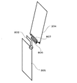
図8および図9は本発明に係る第3実施形態の折畳式携帯電話を示す図である。図8(a)は開き時の背面図、図8(b)は開き時の側面図、図9は閉じ時の側面図である。図8および図9において、図3に示す符号と同一の符号を付すものは同一の構成要素を示しており、その詳細な説明を省略する。なお、アンテナの動作周波数は2GHz帯として説明する。
(Third embodiment)
8 and 9 are views showing a foldable mobile phone according to a third embodiment of the present invention. 8A is a rear view when opened, FIG. 8B is a side view when opened, and FIG. 9 is a side view when closed. 8 and 9, the same reference numerals as those shown in FIG. 3 denote the same components, and a detailed description thereof will be omitted. Note that the operation frequency of the antenna is described as a 2 GHz band.
図8および図9に示す本実施形態の折畳式携帯電話は、上筐体301に、導体素子801、上基板304、液晶表示部306、受話部(スピーカ)803備える。さらに、下筐体302に、給電素子802、下基板305、図示外の整合回路や無線回路、送話部(マイク)804を備える。
The foldable mobile phone of this embodiment shown in FIGS. 8 and 9 includes a
導体素子801は、上筐体301のヒンジ部303近傍において、上基板304に対して受話部803と反対側に配置され、導体素子801と上基板304とは厚み方向に例えば3mmの間隔に設定される。導体素子801は、その主要部が筐体の幅方向(Y軸方向)に平行であり、言い換えればヒンジの回転軸に平行である。導体素子801は、2GHz帯において略4分の1波長の長さ(自由空間で略37.5mm)を有し、その一端が上基板304のヒンジ部303近傍のグランドパターンに電気的に接続され他端は開放端である。筐体の幅は一般に50mm程度であり、導体素子801は、その主要部が筐体の幅方向となり得る。導体素子801の幅は、例えば2mm乃至5mm程度である。
The
給電素子802は、下筐体302のヒンジ部303近傍において、閉じ時に筐体長手方向(Z軸方向)にヒンジ部303から伸張するように配置され、無線回路に整合回路を介して接続される。給電素子802の給電部近傍は筐体長手方向(Z軸方向)に平行である。給電素子802の主要部となる先端部が筐体の幅方向(Y軸方向)に平行であって、言い換えればヒンジの回転軸に平行である。給電素子802は全体として、L字形状をなし、2GHz帯において略4分の1波長の長さ(自由空間で略37.5mm)を有する。給電素子802の幅は、例えば2mm乃至5mm程度である。
The
閉じ時には、図9に示すように、導体素子801が、給電素子802から引き離されるため、電磁的に結合されず、給電素子802が4分の1波長のモノポールアンテナとして動作し、広い帯域、高いアンテナ効率が確保される。
When closed, as shown in FIG. 9, since the
一方、開き時には、図8に示すように、導体素子801と給電素子802は、ヒンジ部303に隣接した位置で、例えば5mm以下の間隔で互いに対向近接し、給電時に電磁的に結合され得る。
On the other hand, at the time of opening, as shown in FIG. 8, the
次に、開き時の動作について図10の概略斜視図を用いてより詳細に説明する。 Next, the opening operation will be described in more detail with reference to the schematic perspective view of FIG.
図10において、矢印は主要部のアンテナ電流を示している。図10(a)は、導体素子801と上基板304のグランドパターンとの接続点を給電素子802の給電部近傍とした場合の折畳式携帯電話800(a)、図10(b)は、導体素子801の開放端を給電素子802の給電部近傍とした場合の折畳式携帯電話800(b)である。導体素子801の長さを2GHz帯における4分の1波長とすることで、給電素子802との電磁的結合が強くなり、導体素子801および上基板304にアンテナ電流が集中する。
In FIG. 10, the arrow indicates the antenna current of the main part. FIG. 10A shows a foldable mobile phone 800 (a) when the connection point between the
このとき、導体素子801および上基板304上のグランドパターンが上側のアンテナ素子として動作し、下基板305上のグランドパターンが下側のアンテナ素子として動作する。すなわち、ダイポールアンテナとして動作するため、直接上筐体を励振したアンテナ構成と同等の特性を得る事ができる。
At this time, the ground pattern on the
また、図10(a)と図10(b)では、導体素子801に流れるアンテナ電流の向きが903と904に示すように反転する。図11は通話状態を示しており、一般に、筐体長手方向(Z軸方向)と地面との角度αは30°程度である。図10(a)の放射特性に対しては筐体長手方向(Z軸方向)のアンテナ電流901と筐体幅方向(Y軸方向)のアンテナ電流903が支配的であり、図11(a)に示すように、使用者が折畳式携帯電話800(a)の下筐体302を左手1001で保持して受話部803を左耳にあてた通話状態において、合成されたアンテナ電流905によって垂直偏波成分が増加する。一方、図10(b)の放射特性に対しては筐体長手方向(Z軸方向)のアンテナ電流901と筐体幅方向(−Y軸方向)のアンテナ電流904が支配的であり、図11(b)に示すように、使用者が折畳式携帯電話800(b)の下筐体302を右手1002で保持して受話部803を右耳にあてた通話状態において、合成されたアンテナ電流906によって垂直偏波成分が増加する。陸上移動通信の多重波環境における一般的な交差偏波電力比は4〜9dBであり、到来波の垂直偏波の電力が水平偏波の電力より4〜9dB高いことが知られている。これは、上述した通話状態における折畳式携帯無線機800(a)および800(b)のアンテナの主偏波が地面に対して垂直であることで、高い通話品質を確保できることを示している。
10A and 10B, the direction of the antenna current flowing through the
さらには、通話状態において、筐体の背面、すなわち人体1000から離隔した部位、特に上筐体301の導体素子801にアンテナ電流が集中するため、頭部1003や手1001および1002の影響によるアンテナ性能の劣化を抑制することができる。
Furthermore, since the antenna current concentrates on the back surface of the housing, that is, the part separated from the
なお、図10(a)の状態では、導体素子801のアンテナ電流903と給電素子802のアンテナ電流902が同相であることから、図10(b)に比べて図10(a)の方が、すなわち、導体素子801と上基板304のグランドパターンとの接続点を給電素子802の給電部近傍とした方が、筐体幅方向の電流によって、より高いアンテナ利得を得ることができる。
In the state of FIG. 10A, the
以上のように、通話する場合、使用者は、単に筐体を開いて受話部を耳に当てる通常の操作をするだけで、頭部や手の影響によるアンテナ性能の劣化を抑制することができ、高いアンテナ利得を得ることができる。 As described above, when making a call, the user can suppress deterioration of the antenna performance due to the influence of the head and hands by simply opening the housing and performing the normal operation of placing the earpiece on the ear. High antenna gain can be obtained.
なお、上記実施形態では、導体素子801の接続先が上基板304上のグランドパターンである場合について述べたが、例えば図12に示すように、上筐体301の内部において、上基板304に対して受話部とは反対側に上基板304と同等以上の大きさを有する導体板805を別途備えて、導体素子801の一端を接続して導体板805および導体素子801を上筐体301の樹脂ケースに貼り付けるように構成してもよい。あるいは、上筐体301のケースがマグネシウム合金などの導電性材料の場合は、導体素子801と導体板805を一体成型してもよい。
In the above embodiment, the case where the connection destination of the
また、導体素子801と上基板304または導体板805を同一平面上に構成することも可能であるが、導体素子801と給電素子802を近接させることによる電磁結合の強化や、頭部1003の影響によるアンテナ性能劣化の抑制の点で、厚み方向において導体素子801と上基板304または導体板805との距離を所定の間隔で配置することが望ましい。
Although the
また、上記実施形態では導体素子801が2GHz帯に対応する場合について述べたが、例えば、図13に示すように、上基板304のグランドパターンとの接点から異なる長さの導体素子806および807(導体素子片あるいは導体素子要素)を備え、それぞれ2GHzと1.8GHzにおける4分の1波長に設定して複数の周波数帯に対応する構成としてもよい。
In the above embodiment, the case where the
また、上記実施形態では給電素子802が2GHz帯に対応する場合について述べたが、例えば、図14に示すように、給電素子802の給電部から異なる長さの給電素子808を別途備え、900MHzにおける4分の1波長に設定して複数の周波数帯に対応する構成としてもよい。この場合、高いアンテナ性能が要求される周波数帯、例えば2GHz帯に対応する給電素子802の方が導体素子801に近接対向するように構成すればよい。
In the above-described embodiment, the case where the
(第4実施形態)
図15および図16は本発明に係る第4実施形態の折畳式携帯電話を示す図である。図15は開き時の側面図、図16は開き時の斜視図である。図15および図16において、図8乃至図14に示す符号と同一の符号を付すものは同一の構成要素を示しており、その詳細な説明を省略する。なお、アンテナの動作周波数は2GHz帯として説明する。
(Fourth embodiment)
15 and 16 are views showing a foldable mobile phone according to a fourth embodiment of the present invention. FIG. 15 is a side view when opened, and FIG. 16 is a perspective view when opened. 15 and 16, the same reference numerals as those shown in FIGS. 8 to 14 denote the same components, and a detailed description thereof will be omitted. Note that the operation frequency of the antenna is described as a 2 GHz band.
図15および図16に示す本実施形態の折畳式携帯電話は、フレキシブルケーブル809、接続コネクタ810および接続コネクタ811を備える。
The foldable mobile phone of this embodiment shown in FIGS. 15 and 16 includes a
フレキシブルケーブル809は、上筐体301内部に配置されて上基板304に実装された液晶表示部306や受話部803に代表される回路部品と、下筐体302内部に配置されて下基板305に実装された図示外の制御回路とを電気的に接続する複数の導電線からなる配線束であり、その片端が接続コネクタ810で上基板304に接続され、他端が下基板305に接続される。上基板304および下基板305の幅は一般に40mm程度であり、フレキシブルケーブル809および接続コネクタ810、接続コネクタ811は、折畳式携帯電話の幅方向において、給電素子820の給電部から例えば30mm離隔した位置に配置され、接続コネクタ810は、導体素子801と上基板304との接続位置からも例えば30mm離隔している。また、フレキシブルケーブル809の長さは例えば20mmである。なお、フレキシブルケーブル809は、ヒンジ部303内を通すため、回動機構に対応できるように一般に柔軟性を有しており、閉じ時に十分な長さを確保するために開き時にはヒンジ部303内で弛みが生じ、図11に示す通話状態においてフレキシブルケーブル809は人体側頭部に近接する。
The
次に、動作について図16の斜視図を用いて説明する。
図16において、矢印は主要部のアンテナ電流を示している。導体素子801の開放端、導体素子801と上基板304との接続位置、フレキシブルケーブル809、給電素子802の給電部、給電素子802の開放端を結ぶ経路は全長が2GHz帯において略1波長となる。導体素子801の開放端および給電素子802の開放端ではアンテナ電流がゼロであり、導体素子801と上基板304との接続位置および給電素子802の給電部ではアンテナ電流が腹、すなわち電流振幅が極大値となり、フレキシブルケーブル809ではアンテナ電流が節、すなわち電流振幅が極小値となる。
Next, the operation will be described with reference to the perspective view of FIG.
In FIG. 16, the arrow indicates the antenna current of the main part. The path connecting the open end of the
一般的に、アンテナ電流分布と局所平均SAR(Specific Absorption Rates:比吸収率)は対応関係にあり、アンテナ電流の極大点が1箇所に集中し、その極大点が人体近傍に存在すると局所平均SARは高くなることが知られている。 In general, the antenna current distribution and the local average SAR (Specific Absorption Rates) have a corresponding relationship. When the local maximum point of the antenna current is concentrated in one place and the local maximum point exists in the vicinity of the human body, the local average SAR Is known to be expensive.
導体素子801がない場合、通話状態において人体側頭部に近接するフレキシブルケーブル809にアンテナ電流が集中して極大値となり、局所平均SARが高くなるが、導体素子801を装荷することによって、フレキシブルケーブル809のアンテナ電流は導体素子801および上基板304の下端(ヒンジ303寄りの一辺)に分散されて、フレキシブルケーブル809のアンテナ電流が略半減することで局所平均SARも略半減する。
When the
以上のように、通話する場合、使用者は、単に筐体を開いて受話部を耳に当てる通常の操作をするだけで、頭部や手の影響によるアンテナ性能の劣化を抑制することができ、高いアンテナ利得を得ることができるとともに、局所平均SARを低減することができる。 As described above, when making a call, the user can suppress deterioration of the antenna performance due to the influence of the head and hands by simply opening the housing and performing the normal operation of placing the earpiece on the ear. A high antenna gain can be obtained and the local average SAR can be reduced.
なお、折畳式携帯電話の幅方向のサイズ、フレキシブルケーブル809と給電素子802の給電部との離隔距離、フレキシブルケーブル809の長さは上記実施例の数値に限るものではなく、例えば、フレキシブルケーブル809と給電素子802の給電部との離隔距離が20mm以上あればある程度の効果が得られ、更には、折畳式携帯電話の幅方向のサイズ、フレキシブルケーブル809と給電素子802の給電部との離隔距離、フレキシブルケーブル809の長さに応じて、導体素子801の長さを適宜設定することで所望の効果が得られる。
Note that the size in the width direction of the folding cellular phone, the separation distance between the
(第5実施形態)
図17は本発明に係る第5実施形態の折畳式携帯電話を示す概略斜視図である。図17において、図8乃至図16に示す符号と同一の符号を付すものは同一の構成要素を示しており、その詳細な説明を省略する。
(Fifth embodiment)
FIG. 17 is a schematic perspective view showing a foldable mobile phone according to a fifth embodiment of the present invention. In FIG. 17, the same reference numerals as those shown in FIGS. 8 to 16 denote the same components, and a detailed description thereof will be omitted.
図17に示す本実施形態の折畳式携帯電話800(c)は、導体素子801の一端と上筐体301の上基板304のグランドパターンとの間には第一切換部を構成する高周波スイッチ812、導体素子801の他端と上筐体301の上基板304のグランドパターンとの間には第二切換部を構成する高周波スイッチ813を備える。
The foldable mobile phone 800 (c) of this embodiment shown in FIG. 17 has a high-frequency switch that constitutes a first switching unit between one end of the
高周波スイッチ812および高周波スイッチ813は、導通または遮断の2つの状態が存在する。高周波スイッチ812が導通、高周波スイッチ813が遮断の場合には、第3実施形態で説明した図10(a)の状態となり、左手で保持して受話部を左耳にあてた通話状態において、高いアンテナ性能を得ることができる。一方、高周波スイッチ812が遮断、高周波スイッチ813が導通の場合には、第3実施形態で説明した図10(b)の状態となり、右手で保持して受話部を右耳にあてた通話状態において、高いアンテナ性能を得ることができる。
The high-
一方、図18は、折畳式携帯電話800(c)を液晶表示部306あるいは図示外の操作部が見えるように使用者が下筐体302を右手で保持した状態を示す図であり、データ通信時、テレビ電話時あるいは操作時の状態である。高周波スイッチ812、高周波スイッチ813が同時に導通、あるいは同時に遮断の時は、導体素子801のアンテナ電流が減少して筐体長手方向のアンテナ電流が増加する。このため、図18に示す保持状態において、垂直偏波成分が増加し、高いアンテナ性能を得ることができる。
On the other hand, FIG. 18 is a diagram showing a state in which the user holds the
以上のように、通話状態や保持状態に応じて、高周波スイッチ812と高周波スイッチ813を制御することで、高いアンテナ性能を得ることができる。
As described above, high antenna performance can be obtained by controlling the high-
なお、高周波スイッチ812および高周波スイッチ813を制御する方法としては、例えば、図示外の無線回路において受信電界強度を検出して受信電界強度が高くなるように制御すればよい。あるいは、図示外の加速度センサーを備えて筐体の傾斜を検出し、その結果から左右の通話状態を判断して制御してもよい。また、図示外の通信制御装置が、通話モードか、データ通信モードかによって、保持状態に対応するように制御してもよい。
In addition, as a method of controlling the
なお、本発明は上述した実施形態に何ら限定されるものではなく、その要旨を逸脱しない範囲において種々の形態で実施し得るものである。 The present invention is not limited to the embodiment described above, and can be implemented in various forms without departing from the gist of the present invention.
本発明によれば、アンテナを突出させることなく、一つのアンテナで開閉の状態に係らず、高いアンテナ性能を得る事ができ、小型化に適した折畳式携帯無線機を提供できる。また、複数のアンテナを必要とせず、シンプルな回路構成で、筐体の小型化、製造コストの削減を図ることが可能となる。本発明は、筐体を折畳む事ができる携帯電話やPHSなどの折畳式携帯無線機器などに有用である。 According to the present invention, it is possible to provide a foldable portable radio device that can obtain high antenna performance without projecting the antenna, regardless of whether the antenna is opened or closed, and is suitable for downsizing. In addition, the housing can be reduced in size and the manufacturing cost can be reduced with a simple circuit configuration without requiring a plurality of antennas. INDUSTRIAL APPLICABILITY The present invention is useful for a folding portable wireless device such as a mobile phone or a PHS that can fold a casing.
101 上筐体
102 下筐体
103 ヒンジ
104 下基板
105 電流の流れ
301 上筐体
302 下筐体
303 ヒンジ
304 上基板
305 下基板
306 LCD
307 給電板金
308 板状導体素子
309 整合回路
310 無線回路
401 高周波結合の流れ
501 上筐体の背面側のケース
502 回路基板との接点部
503 回路基板との接点部
701 グランドピン
702 直流電流の流れ
703 接点部
704 導通孔
800(a)、800(b) 折畳式携帯電話
801、806、807 導体素子
802、808 給電素子
803 受話部(スピーカ)
804 送話部(マイク)
805 導体板
809 フレキシブルケーブル
810、811 接続コネクタ
812、813 高周波スイッチ
901、902、903、904、905、906、907、908 アンテナ電流
1000 人体
1001 左手
1002 右手
1003 頭部
101
307
804 Transmitter (microphone)
805
Claims (11)
第二の筐体と、
前記第一の筐体と前記第二の筐体を開閉可能に接続する連結部と、
前記第一の筐体の前記連結部に隣接した端部に配置された導体素子と、
前記第二の筐体の前記連結部に隣接した端部に配置された給電素子と、を備え、
前記連結部による開き状態において、前記導体素子及び前記給電素子は、互いに対向して配置され、給電時に容量結合可能であり、
前記連結部による閉じ状態において、前記導体素子及び前記給電素子は、前記連結部を隔てて配置される、
折畳式携帯無線機。 A first housing;
A second housing;
A connecting portion that connects the first housing and the second housing so as to be openable and closable;
A conductor element disposed at an end adjacent to the connecting portion of the first housing;
And a feed element arranged in the end adjacent to the connecting portion of the second housing,
In the open state by the connecting portion, the conductor element and the power feeding element are arranged to face each other, and can be capacitively coupled during power feeding,
In the closed state by the connecting portion, the conductor element and the power feeding element are disposed with the connecting portion therebetween.
Folding portable radio.
Priority Applications (4)
| Application Number | Priority Date | Filing Date | Title |
|---|---|---|---|
| JP2004324136A JP4358084B2 (en) | 2004-07-12 | 2004-11-08 | Foldable portable radio |
| US11/571,747 US7787915B2 (en) | 2004-07-12 | 2005-07-12 | Folding type portable wireless unit |
| EP05765647A EP1770824A4 (en) | 2004-07-12 | 2005-07-12 | Folding type portable wireless unit |
| PCT/JP2005/012848 WO2006006599A1 (en) | 2004-07-12 | 2005-07-12 | Folding type portable wireless unit |
Applications Claiming Priority (2)
| Application Number | Priority Date | Filing Date | Title |
|---|---|---|---|
| JP2004204343 | 2004-07-12 | ||
| JP2004324136A JP4358084B2 (en) | 2004-07-12 | 2004-11-08 | Foldable portable radio |
Publications (3)
| Publication Number | Publication Date |
|---|---|
| JP2006054843A JP2006054843A (en) | 2006-02-23 |
| JP2006054843A5 JP2006054843A5 (en) | 2009-08-06 |
| JP4358084B2 true JP4358084B2 (en) | 2009-11-04 |
Family
ID=35783938
Family Applications (1)
| Application Number | Title | Priority Date | Filing Date |
|---|---|---|---|
| JP2004324136A Expired - Fee Related JP4358084B2 (en) | 2004-07-12 | 2004-11-08 | Foldable portable radio |
Country Status (4)
| Country | Link |
|---|---|
| US (1) | US7787915B2 (en) |
| EP (1) | EP1770824A4 (en) |
| JP (1) | JP4358084B2 (en) |
| WO (1) | WO2006006599A1 (en) |
Families Citing this family (48)
| Publication number | Priority date | Publication date | Assignee | Title |
|---|---|---|---|---|
| JP4661180B2 (en) * | 2004-11-19 | 2011-03-30 | 日本電気株式会社 | Portable wireless terminal and antenna current grounding method |
| ES2661171T3 (en) * | 2006-04-18 | 2018-03-27 | Qualcomm Incorporated | Mobile terminal with a monopole type antenna |
| JP4691595B2 (en) * | 2006-07-06 | 2011-06-01 | シャープ株式会社 | transceiver |
| US8738103B2 (en) | 2006-07-18 | 2014-05-27 | Fractus, S.A. | Multiple-body-configuration multimedia and smartphone multifunction wireless devices |
| JP5042228B2 (en) * | 2006-09-21 | 2012-10-03 | 京セラ株式会社 | Portable radio |
| JP2008118359A (en) * | 2006-11-02 | 2008-05-22 | Nec Corp | Walkie-talkie |
| JP4905126B2 (en) * | 2006-12-28 | 2012-03-28 | 日本電気株式会社 | Portable wireless terminal |
| JP5245833B2 (en) | 2007-01-11 | 2013-07-24 | 日本電気株式会社 | Mobile phone |
| JP4694517B2 (en) * | 2007-02-26 | 2011-06-08 | 京セラ株式会社 | Portable electronic devices |
| JP4836850B2 (en) * | 2007-02-27 | 2011-12-14 | 京セラ株式会社 | Communication equipment |
| JP4805187B2 (en) * | 2007-02-27 | 2011-11-02 | 京セラ株式会社 | Wireless communication device |
| JP5188838B2 (en) * | 2007-02-27 | 2013-04-24 | 京セラ株式会社 | Communication equipment |
| JP4915255B2 (en) * | 2007-03-06 | 2012-04-11 | 日本電気株式会社 | Portable radio |
| JP4818973B2 (en) * | 2007-03-29 | 2011-11-16 | 京セラ株式会社 | Mobile terminal device |
| EP2157663B9 (en) * | 2007-04-13 | 2014-02-26 | Murata Manufacturing Co. Ltd. | Radio communication device |
| JP4853368B2 (en) * | 2007-04-16 | 2012-01-11 | 株式会社村田製作所 | Wireless communication device |
| JP4896807B2 (en) * | 2007-04-26 | 2012-03-14 | 京セラ株式会社 | Communication equipment |
| JP5082136B2 (en) * | 2007-11-20 | 2012-11-28 | Necカシオモバイルコミュニケーションズ株式会社 | Wireless communication device |
| WO2009081638A1 (en) * | 2007-12-20 | 2009-07-02 | Nec Corporation | Portable terminal |
| JP4983615B2 (en) * | 2008-01-16 | 2012-07-25 | ソニー株式会社 | COMMUNICATION DEVICE AND METHOD, AND FUNCTIONAL MODULE |
| JP5489475B2 (en) * | 2008-01-30 | 2014-05-14 | 京セラ株式会社 | Portable electronic devices |
| WO2009154053A1 (en) | 2008-06-19 | 2009-12-23 | シャープ株式会社 | Wireless device |
| WO2009154054A1 (en) * | 2008-06-19 | 2009-12-23 | シャープ株式会社 | Wireless apparatus |
| JP5222175B2 (en) * | 2008-11-20 | 2013-06-26 | 京セラ株式会社 | Communication processing device |
| JP5226556B2 (en) * | 2008-11-20 | 2013-07-03 | 京セラ株式会社 | Communication processing device |
| US8866694B2 (en) * | 2008-11-26 | 2014-10-21 | Kyocera Corporation | Portable terminal |
| JP2010141712A (en) * | 2008-12-12 | 2010-06-24 | Panasonic Corp | Mobile wireless unit |
| WO2010074262A1 (en) * | 2008-12-25 | 2010-07-01 | 京セラ株式会社 | Wireless terminal device |
| JP5222716B2 (en) * | 2008-12-25 | 2013-06-26 | 京セラ株式会社 | Mobile device |
| JP2010278609A (en) * | 2009-05-27 | 2010-12-09 | Panasonic Corp | Portable radio device |
| KR20100133536A (en) * | 2009-06-12 | 2010-12-22 | 삼성전자주식회사 | Built-in antenna for folder type portable terminal |
| JP5345916B2 (en) * | 2009-09-17 | 2013-11-20 | 日本電気株式会社 | Antenna structure, radio communication apparatus, and antenna configuration method |
| KR101586288B1 (en) * | 2009-10-06 | 2016-01-19 | 주식회사 이엠따블유 | Folder type portable terminal comprising parasitic element |
| WO2011095330A1 (en) | 2010-02-02 | 2011-08-11 | Fractus, S.A. | Antennaless wireless device comprising one or more bodies |
| EP2362612B1 (en) | 2010-02-15 | 2012-05-09 | Research In Motion Limited | Portable electronic device having at least one of resonator and shield |
| EP2549586A1 (en) * | 2010-03-19 | 2013-01-23 | Nec Corporation | Electronic apparatus |
| CN102859788A (en) * | 2010-03-31 | 2013-01-02 | 日本电气株式会社 | Wireless communication device, impedance adjustment method, casing position detection method, and information display method |
| JP5565858B2 (en) * | 2010-04-26 | 2014-08-06 | Necカシオモバイルコミュニケーションズ株式会社 | Mobile communication terminal |
| WO2011135851A1 (en) | 2010-04-27 | 2011-11-03 | パナソニック株式会社 | Wireless terminal |
| JP5619565B2 (en) * | 2010-10-27 | 2014-11-05 | 京セラ株式会社 | Communication device |
| JP2016154271A (en) * | 2013-06-21 | 2016-08-25 | 旭硝子株式会社 | Antenna and wireless unit including the same |
| KR102519205B1 (en) | 2017-03-06 | 2023-04-11 | 스냅 인코포레이티드 | Wearable device antenna system |
| EP3583657A4 (en) * | 2017-04-13 | 2020-11-11 | Hewlett-Packard Development Company, L.P. | An antenna for an electronic device |
| KR102483631B1 (en) * | 2018-06-11 | 2023-01-03 | 삼성전자주식회사 | An electronic device comprising an antenna |
| CN113972496B (en) * | 2019-05-13 | 2022-09-09 | 华为技术有限公司 | Electronic device |
| CN110232868B (en) * | 2019-05-31 | 2022-01-25 | Oppo广东移动通信有限公司 | Housing, housing assembly and electronic device |
| JP6820068B1 (en) * | 2019-07-25 | 2021-01-27 | Necプラットフォームズ株式会社 | Wireless device |
| CN113193344B (en) * | 2021-04-28 | 2022-11-25 | 安徽华米健康医疗有限公司 | Electronic device and antenna control method thereof |
Family Cites Families (21)
| Publication number | Priority date | Publication date | Assignee | Title |
|---|---|---|---|---|
| EP0861508A1 (en) * | 1995-11-15 | 1998-09-02 | Allgon Ab | Compact antenna means for portable radio communication devices and switch-less antenna connecting means therefor |
| JP3767030B2 (en) * | 1996-09-09 | 2006-04-19 | 三菱電機株式会社 | Foldable wireless communication device |
| JPH11127010A (en) * | 1997-10-22 | 1999-05-11 | Sony Corp | Antenna system and portable radio equipment |
| JP3635195B2 (en) * | 1997-11-04 | 2005-04-06 | アルプス電気株式会社 | Mobile phone |
| SE9801381D0 (en) * | 1998-04-20 | 1998-04-20 | Allgon Ab | Ground extension arrangement for coupling to ground means in an antenna system, and an antenna system and a mobile radio device having such ground arrangement |
| JP3538134B2 (en) | 1999-09-14 | 2004-06-14 | 埼玉日本電気株式会社 | Mobile phone |
| US6246374B1 (en) * | 2000-04-06 | 2001-06-12 | Motorola, Inc. | Passive flip radiator for antenna enhancement |
| EP1209759B1 (en) * | 2000-11-22 | 2006-05-31 | Matsushita Electric Industrial Co., Ltd. | Antenna and wireless device incorporating the same |
| JP3830773B2 (en) * | 2001-05-08 | 2006-10-11 | 三菱電機株式会社 | Mobile phone |
| JP3631696B2 (en) * | 2001-06-25 | 2005-03-23 | 埼玉日本電気株式会社 | Portable radio |
| JP3959332B2 (en) | 2001-10-24 | 2007-08-15 | 松下電器産業株式会社 | Portable wireless terminal |
| EP1306922A3 (en) * | 2001-10-24 | 2006-08-16 | Matsushita Electric Industrial Co., Ltd. | Antenna structure, methof of using antenna structure and communication device |
| JP2003204821A (en) | 2002-01-17 | 2003-07-22 | Yoshida Industry Co Ltd | Compact container for cosmetics |
| US6600450B1 (en) * | 2002-03-05 | 2003-07-29 | Motorola, Inc. | Balanced multi-band antenna system |
| JP4071554B2 (en) | 2002-06-18 | 2008-04-02 | 松下電器産業株式会社 | Antenna device |
| AU2003281595A1 (en) * | 2002-07-19 | 2004-02-09 | Matsushita Electric Industrial Co., Ltd. | Portable wireless machine |
| JP3613525B2 (en) | 2002-07-19 | 2005-01-26 | 松下電器産業株式会社 | Portable radio |
| JP4187478B2 (en) | 2002-08-08 | 2008-11-26 | ソニー・エリクソン・モバイルコミュニケーションズ株式会社 | Portable wireless communication terminal |
| JP4150621B2 (en) * | 2002-09-20 | 2008-09-17 | 富士通株式会社 | Foldable portable radio and chassis of the radio |
| JP3789424B2 (en) * | 2002-11-20 | 2006-06-21 | 埼玉日本電気株式会社 | Mobile device |
| JP5062953B2 (en) * | 2004-12-09 | 2012-10-31 | 富士通株式会社 | ANTENNA DEVICE AND WIRELESS COMMUNICATION DEVICE |
-
2004
- 2004-11-08 JP JP2004324136A patent/JP4358084B2/en not_active Expired - Fee Related
-
2005
- 2005-07-12 US US11/571,747 patent/US7787915B2/en not_active Expired - Fee Related
- 2005-07-12 WO PCT/JP2005/012848 patent/WO2006006599A1/en not_active Application Discontinuation
- 2005-07-12 EP EP05765647A patent/EP1770824A4/en not_active Withdrawn
Also Published As
| Publication number | Publication date |
|---|---|
| JP2006054843A (en) | 2006-02-23 |
| US7787915B2 (en) | 2010-08-31 |
| EP1770824A1 (en) | 2007-04-04 |
| US20080300028A1 (en) | 2008-12-04 |
| WO2006006599A1 (en) | 2006-01-19 |
| EP1770824A4 (en) | 2007-12-19 |
Similar Documents
| Publication | Publication Date | Title |
|---|---|---|
| JP4358084B2 (en) | Foldable portable radio | |
| JP4850839B2 (en) | Portable radio | |
| JP4572580B2 (en) | Foldable portable radio | |
| JP4242780B2 (en) | Balanced multiband antenna device | |
| US8090419B2 (en) | Folding portable wireless apparatus | |
| JP4146478B2 (en) | Wireless module and portable terminal | |
| JP4948177B2 (en) | Foldable portable radio | |
| EP1482646B1 (en) | Portable terminal having tuner for changing radiation pattern | |
| JP4197734B2 (en) | Wireless module | |
| JP4227141B2 (en) | Antenna device | |
| JP5355897B2 (en) | Portable radio | |
| JP2004104419A (en) | Antenna for portable radio | |
| JPWO2007043138A1 (en) | Folding portable wireless device | |
| JPWO2006112160A1 (en) | Foldable portable radio | |
| JPWO2006057350A1 (en) | Folding portable wireless device | |
| JP4189433B1 (en) | Portable radio | |
| JP2006157787A (en) | Foldable portable wireless device | |
| JP4734204B2 (en) | mobile phone | |
| JP2006067133A (en) | Folding type portable radio device | |
| JP2002171111A (en) | Portable radio and antenna for it | |
| JP4124803B1 (en) | Portable radio | |
| WO2011067943A1 (en) | Portable radio | |
| KR101218675B1 (en) | Intena apparatus and mobile terminal having the same | |
| WO2014002378A1 (en) | Antenna device and portable radio equipment | |
| JP2002320017A (en) | Portable radio device |
Legal Events
| Date | Code | Title | Description |
|---|---|---|---|
| A621 | Written request for application examination |
Free format text: JAPANESE INTERMEDIATE CODE: A621 Effective date: 20070928 |
|
| RD02 | Notification of acceptance of power of attorney |
Free format text: JAPANESE INTERMEDIATE CODE: A7422 Effective date: 20071113 |
|
| RD04 | Notification of resignation of power of attorney |
Free format text: JAPANESE INTERMEDIATE CODE: A7424 Effective date: 20071120 |
|
| A521 | Request for written amendment filed |
Free format text: JAPANESE INTERMEDIATE CODE: A523 Effective date: 20090619 |
|
| A871 | Explanation of circumstances concerning accelerated examination |
Free format text: JAPANESE INTERMEDIATE CODE: A871 Effective date: 20090619 |
|
| TRDD | Decision of grant or rejection written | ||
| A975 | Report on accelerated examination |
Free format text: JAPANESE INTERMEDIATE CODE: A971005 Effective date: 20090702 |
|
| A01 | Written decision to grant a patent or to grant a registration (utility model) |
Free format text: JAPANESE INTERMEDIATE CODE: A01 Effective date: 20090707 |
|
| A01 | Written decision to grant a patent or to grant a registration (utility model) |
Free format text: JAPANESE INTERMEDIATE CODE: A01 |
|
| A61 | First payment of annual fees (during grant procedure) |
Free format text: JAPANESE INTERMEDIATE CODE: A61 Effective date: 20090805 |
|
| FPAY | Renewal fee payment (event date is renewal date of database) |
Free format text: PAYMENT UNTIL: 20120814 Year of fee payment: 3 |
|
| R150 | Certificate of patent or registration of utility model |
Ref document number: 4358084 Country of ref document: JP Free format text: JAPANESE INTERMEDIATE CODE: R150 Free format text: JAPANESE INTERMEDIATE CODE: R150 |
|
| FPAY | Renewal fee payment (event date is renewal date of database) |
Free format text: PAYMENT UNTIL: 20130814 Year of fee payment: 4 |
|
| LAPS | Cancellation because of no payment of annual fees |