JP2010141712A - Mobile wireless unit - Google Patents
Mobile wireless unit Download PDFInfo
- Publication number
- JP2010141712A JP2010141712A JP2008317204A JP2008317204A JP2010141712A JP 2010141712 A JP2010141712 A JP 2010141712A JP 2008317204 A JP2008317204 A JP 2008317204A JP 2008317204 A JP2008317204 A JP 2008317204A JP 2010141712 A JP2010141712 A JP 2010141712A
- Authority
- JP
- Japan
- Prior art keywords
- housing
- circuit board
- connection cable
- hinge portion
- hinge
- Prior art date
- Legal status (The legal status is an assumption and is not a legal conclusion. Google has not performed a legal analysis and makes no representation as to the accuracy of the status listed.)
- Withdrawn
Links
Images


Classifications
-
- H—ELECTRICITY
- H01—ELECTRIC ELEMENTS
- H01Q—ANTENNAS, i.e. RADIO AERIALS
- H01Q1/00—Details of, or arrangements associated with, antennas
- H01Q1/12—Supports; Mounting means
- H01Q1/22—Supports; Mounting means by structural association with other equipment or articles
- H01Q1/24—Supports; Mounting means by structural association with other equipment or articles with receiving set
- H01Q1/241—Supports; Mounting means by structural association with other equipment or articles with receiving set used in mobile communications, e.g. GSM
- H01Q1/242—Supports; Mounting means by structural association with other equipment or articles with receiving set used in mobile communications, e.g. GSM specially adapted for hand-held use
- H01Q1/243—Supports; Mounting means by structural association with other equipment or articles with receiving set used in mobile communications, e.g. GSM specially adapted for hand-held use with built-in antennas
-
- H—ELECTRICITY
- H01—ELECTRIC ELEMENTS
- H01Q—ANTENNAS, i.e. RADIO AERIALS
- H01Q9/00—Electrically-short antennas having dimensions not more than twice the operating wavelength and consisting of conductive active radiating elements
- H01Q9/04—Resonant antennas
- H01Q9/16—Resonant antennas with feed intermediate between the extremities of the antenna, e.g. centre-fed dipole
- H01Q9/28—Conical, cylindrical, cage, strip, gauze, or like elements having an extended radiating surface; Elements comprising two conical surfaces having collinear axes and adjacent apices and fed by two-conductor transmission lines
Abstract
Description
本発明は、折り畳み可能な筐体内にアンテナを搭載した携帯無線装置に関する。 The present invention relates to a portable wireless device in which an antenna is mounted in a foldable casing.
携帯電話端末のような携帯無線装置では、2つに分離された筐体がヒンジ部を介して連結され、筐体の開閉や折り畳みが可能な構造のものが広く用いられている。この種の携帯無線装置において、筐体自体あるいは筐体内に搭載した回路基板をアンテナとして機能させるいわゆる筐体ダイポール方式のアンテナを備えるものがある。 2. Description of the Related Art Mobile wireless devices such as mobile phone terminals are widely used in such a structure that two separate housings are connected via a hinge portion so that the housing can be opened / closed and folded. Some portable wireless devices of this type include a so-called housing dipole antenna that allows the housing itself or a circuit board mounted in the housing to function as an antenna.
筐体をアンテナとして機能させる携帯無線装置としては、例えば特許文献1には、第1の筐体に設けられるアンテナ素子と、第1の筐体と第2の筐体とを回動自在に連結するとともにアンテナ素子と電気的に接続される導電性のヒンジ部と、第2の筐体内に設けられる回路基板からヒンジ部に給電するための給電部とを備え、第1の筐体をアンテナ素子として機能させることが可能な携帯無線装置が開示されている。
As a portable wireless device that causes a housing to function as an antenna, for example, in
図8は筐体ダイポール方式のアンテナを備える携帯無線装置の構成例を示す図である。左図は背面から見たもので、右図は筐体背面の右側面からみたものである。この例では、第一筐体101、第二筐体102、これらの筐体を回動可能に連結し、導電性の金属で構成されたヒンジ部103を備え、第一筐体101には第一回路基板104が設けられ、第二筐体102には第二回路基板105が設けられている。ヒンジ部103は第一筐体101または第二筐体102のいずれかに収容されている。ヒンジ部103の近傍には、ヒンジ部103から所定の距離をもってアンテナ素子106が設けられ、給電部107を介して第二筐体102内の第二回路基板105に搭載された整合回路108、無線回路109と接続されている。また、第一回路基板104と第二回路基板105とは、信号の入出力やグランド接続等のために接続ケーブル110によって接続されている。この構成において、給電部107によって無線回路109からアンテナ素子106に給電し、アンテナ素子106はヒンジ部103に容量結合し、ヒンジ部103と第一筐体101内の第一回路基板104とを容量結合させることによって、筐体を開いた状態においてヒンジ部103および第一回路基板104がアンテナ素子として機能し、ダイポール動作する。このような筐体ダイポールアンテナの構成によって、アンテナ体積を大きく確保できるので、アンテナ性能の高性能化、広帯域化が容易に可能となる。筐体ダイポールアンテナ構成においては、接続ケーブル110はグランド接続であるため、給電部から所定の距離をもって配置されるのが望ましい。
携帯無線装置は、筐体の小型化やデザインとアンテナ性能の両立の点で、アンテナの配置やスペースの制約が大きい。特に、筐体ダイポールアンテナ構成では、導電性の金属で構成されたヒンジ部とアンテナ素子を同一筐体に収容することは小型化を困難とするため、例えば、第一筐体101にヒンジ部を配置すると、アンテナ素子は第二筐体102に配置される。このような筐体ダイポールアンテナ構成において、導電性のヒンジ部を筐体内のグランドと接続し、ヒンジ部をグランドとして機能させるものがある。また、特許文献2に記載されているように、2つのヒンジ部を備え、筐体の短手方向に沿った回動軸を持つ第1のヒンジ部によって回動し、筐体の長手方向に開閉可能であるとともに、筐体の長手方向に沿った回動軸を持つ第2のヒンジ部によって回動し、筐体の短手方向に開閉可能に構成された両開き構造のものが提案されている。
The portable wireless device is greatly limited in antenna arrangement and space in terms of miniaturization of the housing and compatibility between design and antenna performance. In particular, in the case of the case dipole antenna configuration, it is difficult to reduce the size of the
上記の両開き構造のものなど、構造的な制約が大きい場合には、第一筐体と第二筐体とを接続する接続ケーブルを、ヒンジ部の内部などの限定された空間に配置する必要がある。例えば、ヒンジ部をグランドに接続し、ヒンジ部の内部に接続ケーブルを挿通させた場合、グランドであるヒンジ部の内部を異なるインピーダンスをもつ接続ケーブルが挿通するため、互いの電流が干渉し、アンテナ性能を劣化させる課題をもつ。 When structural restrictions are large, such as those with the double opening structure described above, it is necessary to arrange the connection cable for connecting the first housing and the second housing in a limited space such as the inside of the hinge portion. is there. For example, when the hinge part is connected to the ground and the connection cable is inserted inside the hinge part, the connection cables having different impedances are inserted through the inside of the hinge part, which is the ground. Has the problem of degrading performance.
本発明は、上記事情に鑑みてなされたもので、導電性のヒンジ部内部に筐体間を接続する接続ケーブルが挿通する構成とした場合に、アンテナ性能を改善することが可能な携帯無線装置を提供することを目的とする。 The present invention has been made in view of the above circumstances, and a portable wireless device capable of improving antenna performance when a connection cable for connecting between casings is inserted inside a conductive hinge portion. The purpose is to provide.
本発明は、第一筐体と、前記第一筐体内に設けられる第一回路基板と、第二筐体と、前記第二筐体内に設けられる第二回路基板と、前記第一回路基板または前記第二回路基板のいずれか一方に設けられた無線回路と、前記無線回路に接続されるアンテナ素子と、前記第一筐体と前記第二筐体を回動可能に連結し、導電性部材で構成され、内部が中空のヒンジ部と、前記ヒンジ部内を挿通され、前記第一回路基板と前記第二回路基板を電気的に接続する接続ケーブルと、を備え、前記ヒンジ部がグランドと接続されて前記アンテナ素子のグランドとして機能し、前記ヒンジ部と前記接続ケーブルの導体部とが所定の距離を保って配置される携帯無線装置を提供する。
上記構成により、ヒンジ部と接続ケーブルの導体部との間の電気的な結合が弱くなり、導電性のヒンジ部内部に筐体間を接続する接続ケーブルが挿通する構成とした場合に、ヒンジ部と接続ケーブルとの間における互いの影響を軽減でき、アンテナ性能を改善することが可能となる。
The present invention includes a first casing, a first circuit board provided in the first casing, a second casing, a second circuit board provided in the second casing, the first circuit board, A wireless circuit provided on any one of the second circuit boards, an antenna element connected to the wireless circuit, the first housing and the second housing are rotatably connected, and a conductive member A hinge part having a hollow inside, and a connection cable that is inserted through the hinge part and electrically connects the first circuit board and the second circuit board, and the hinge part is connected to the ground. Thus, a portable wireless device is provided that functions as a ground of the antenna element and in which the hinge portion and the conductor portion of the connection cable are arranged at a predetermined distance.
With the above configuration, when the electrical connection between the hinge portion and the conductor portion of the connection cable is weakened, and the connection cable connecting between the housings is inserted into the conductive hinge portion, the hinge portion It is possible to reduce the mutual influence between the cable and the connection cable, and to improve the antenna performance.
また、本発明は、第一筐体と、前記第一筐体内に設けられる第一回路基板と、第二筐体と、前記第二筐体内に設けられる第二回路基板と、前記第一回路基板または前記第二回路基板のいずれか一方に設けられた無線回路と、前記無線回路に接続されるアンテナ素子と、前記第一筐体と前記第二筐体との間に設けられた第三の筐体と、前記第一筐体と第三筐体を第一回動軸を中心に回動可能に連結する第一ヒンジ部と、前記第二筐体と第三筐体を前記第一回動軸と垂直な第二回動軸を中心に回動可能に連結し、導電性部材で構成され、内部が中空の第二ヒンジ部と、前記第二ヒンジ部内に挿通され、前記第一回路基板と前記第二回路基板を電気的に接続する接続ケーブルと、を備え、前記第二ヒンジ部がグランドと接続されて前記アンテナ素子のグランドとして機能し、前記第二ヒンジ部と前記接続ケーブルの導体部とが所定の距離を保って配置される携帯無線装置を提供する。
上記構成により、ヒンジ部と接続ケーブルの導体部との間の電気的な結合が弱くなり、導電性のヒンジ部内部に筐体間を接続する接続ケーブルが挿通する構成とした場合に、ヒンジ部と接続ケーブルの導体部との間における互いの影響を軽減でき、アンテナ性能を改善することが可能となる。特に、第一ヒンジ部と第二ヒンジ部を有する構成において、構造上の制約からアンテナ素子の給電部とヒンジ部のグランドとが近接して配置される場合などに、ヒンジ部のグランドやアンテナ素子の給電部に対する接続ケーブルの影響を軽減でき、高いアンテナ性能を得ることができる。
The present invention also provides a first housing, a first circuit board provided in the first housing, a second housing, a second circuit board provided in the second housing, and the first circuit. A wireless circuit provided on either the substrate or the second circuit board, an antenna element connected to the wireless circuit, and a third provided between the first casing and the second casing A first hinge portion that connects the first housing and the third housing so as to be rotatable about a first rotation axis, and the second housing and the third housing are connected to the first housing. A second hinge shaft that is perpendicular to the pivot shaft is pivotally connected to each other, and is composed of a conductive member. The interior of the second hinge portion is hollow and inserted into the second hinge portion. A connection cable for electrically connecting the circuit board and the second circuit board, wherein the second hinge portion is connected to a ground and the antenna element Functions as a ground, and the second hinge portion and the conductor portion of the connecting cables to provide a mobile radio device arranged with a predetermined distance.
With the above configuration, the electrical connection between the hinge portion and the conductor portion of the connection cable is weakened, and when the connection cable connecting between the casings is inserted into the conductive hinge portion, the hinge portion And the conductor portion of the connecting cable can be reduced, and the antenna performance can be improved. In particular, in the configuration having the first hinge portion and the second hinge portion, when the feeding portion of the antenna element and the ground of the hinge portion are arranged close to each other due to structural limitations, the ground of the hinge portion or the antenna element The influence of the connection cable on the power feeding section can be reduced, and high antenna performance can be obtained.
また、本発明は、上記の携帯無線装置であって、前記アンテナ素子は前記第三筐体内に配置され、前記第三筐体内において前記アンテナ素子と前記第二ヒンジ部とが整合回路を介して接続されているものを含む。
上記構成により、例えばいわゆる逆ヒンジ構造となっている場合など、第一ヒンジ部と第二ヒンジ部を有する構成において第三筐体内にアンテナ素子が配置され、構造上の制約がある場合に、ヒンジ部と接続ケーブルの導体部との間の電気的な結合を低減し、ヒンジ部のグランドやアンテナ素子の給電部に対する接続ケーブルの影響を軽減でき、アンテナ性能を改善することが可能となる。
Further, the present invention is the above-described portable wireless device, wherein the antenna element is disposed in the third housing, and the antenna element and the second hinge portion are interposed in the third housing via a matching circuit. Includes connected ones.
When the antenna element is arranged in the third housing in the configuration having the first hinge portion and the second hinge portion, for example, when a so-called reverse hinge structure is used, the hinge is It is possible to reduce the electrical coupling between the connection portion and the conductor portion of the connection cable, reduce the influence of the connection cable on the ground of the hinge portion and the feeding portion of the antenna element, and improve the antenna performance.
また、本発明は、上記の携帯無線装置であって、前記第二ヒンジ部と前記接続ケーブルの導体部との間の容量値が所定値以下となるように、前記第二ヒンジ部と前記接続ケーブルの導体部とは互いに所定の距離以上離して配置されるものを含む。
上記構成により、第二ヒンジ部と接続ケーブルの導体部とを互いに所定の距離以上離して配置し、第二ヒンジ部と接続ケーブルの導体部との間の容量値が所定値以下となることによって、ヒンジ部と接続ケーブルの導体部との間の電気的な結合を弱めて、接続ケーブルの影響を軽減し、アンテナ性能を改善することができる。
Further, the present invention is the portable wireless device described above, wherein the second hinge portion and the connection are connected so that a capacitance value between the second hinge portion and the conductor portion of the connection cable is a predetermined value or less. The conductor part of the cable includes those arranged at a predetermined distance or more away from each other.
With the above configuration, the second hinge part and the conductor part of the connection cable are arranged apart from each other by a predetermined distance, and the capacitance value between the second hinge part and the conductor part of the connection cable becomes equal to or less than a predetermined value. It is possible to weaken the electrical coupling between the hinge part and the conductor part of the connection cable, reduce the influence of the connection cable, and improve the antenna performance.
また、本発明は、上記いずれかの携帯無線装置であって、前記接続ケーブルは同軸ケーブルを有して構成され、この同軸ケーブルの外導体部とグランドとの間にインダクタを含む所定インピーダンスを有するインピーダンス素子を備えるものを含む。
上記構成により、例えばヒンジ部と接続ケーブルの導体部との間の距離が大きくとれず、容量値が十分小さくできない場合であっても、インピーダンス素子のインダクタとヒンジ部及び接続ケーブル間の容量とのLC共振によって、所望のアンテナ性能改善効果を得ることができる。
Also, the present invention is any one of the portable radio devices described above, wherein the connection cable includes a coaxial cable, and has a predetermined impedance including an inductor between the outer conductor portion of the coaxial cable and the ground. Includes those with impedance elements.
With the above configuration, for example, even if the distance between the hinge portion and the conductor portion of the connection cable cannot be increased, and the capacitance value cannot be sufficiently reduced, the impedance between the inductor of the impedance element and the capacitance between the hinge portion and the connection cable can be reduced. A desired antenna performance improvement effect can be obtained by LC resonance.
本発明によれば、導電性のヒンジ部内部に筐体間を接続する接続ケーブルが挿通する構成とした場合に、アンテナ性能を改善することが可能な携帯無線装置を提供できる。 ADVANTAGE OF THE INVENTION According to this invention, when it is set as the structure by which the connection cable which connects between housing | casings is penetrated inside an electroconductive hinge part, the portable radio | wireless apparatus which can improve antenna performance can be provided.
以下の実施形態では、携帯電話機等の折り畳み可能な筐体を持つ携帯端末装置に適用した場合の携帯無線装置の構成例を示す。なお、本発明は、使用者が携帯可能な種々の携帯無線装置に適用可能である。 In the following embodiment, a configuration example of a portable wireless device when applied to a portable terminal device having a foldable casing such as a cellular phone is shown. The present invention can be applied to various portable wireless devices that can be carried by the user.
まず、折り畳み型の筐体の構成、及び対応するアンテナの配置構成について説明する。図1は折り畳み型の筐体を持つ携帯無線装置の構成例を示す図であり、図1(A)は第1例を、図1(B)は第2例をそれぞれ示したものである。図1(A)、図1(B)それぞれにおいて、左側は筐体を背面から見た図で、右側は筐体背面の右側面から見た図であり、筐体内部の各構成要素が見える形に模式的に示してある。 First, the configuration of the foldable casing and the corresponding antenna arrangement will be described. 1A and 1B are diagrams illustrating a configuration example of a portable wireless device having a foldable housing. FIG. 1A shows a first example, and FIG. 1B shows a second example. In each of FIG. 1A and FIG. 1B, the left side is a view of the housing viewed from the back, and the right side is a view of the housing from the right side, so that each component inside the housing can be seen. The shape is shown schematically.
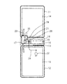
図1(A)に示す第1例は、一般的な両開き構造の筐体を有するものである。この第1例では、第一筐体51と第二筐体52との間に、ヒンジ部を内蔵した第三筐体53を備え、第一筐体51には第一回路基板54が設けられ、第二筐体52には第二回路基板55が設けられている。第三筐体53には、図示した状態のように筐体を長手方向に開閉させるための、筐体の短手方向に沿った第一回動軸を持つ第一ヒンジ部56と、筐体を短手方向に開閉させるための、筐体の長手方向に沿った第二回動軸を持つ第二ヒンジ部57とが設けられている。第一ヒンジ部56は、第二筐体52と第三筐体53とを連結しており、第二筐体52に対して前記第一回動軸を中心に第一筐体51及び第三筐体53を回動可能にするものである。第二ヒンジ部57は、第一筐体51と第三筐体53とを連結しており、前記第二回動軸を中心に第二筐体52及び第三筐体53に対して第一筐体51を回動可能にするものである。ここで、図1(A)の側面図において、第一ヒンジ部56と第二ヒンジ部57は第一筐体51の長手方向延長線上に沿って配置している。
The first example shown in FIG. 1A has a general double-open casing. In the first example, a
この場合、第二筐体52内のヒンジ部近傍に、アンテナ素子58を実装したアンテナ基板59が設けられる。図1(A)の平面図では第一ヒンジ部56が図示されていないが、平面図においてアンテナ基板59と重なる位置で第二筐体52内に配置されている。このアンテナ素子58は、給電部60を介して第二回路基板55と接続され、第二回路基板55に搭載された整合回路61、無線回路62と接続されている。また、信号の入出力等のための接続ケーブル63が第二ヒンジ部57の内部を挿通して設けられ、この接続ケーブル63は、複数の細線同軸等により構成され、第一回路基板54と第二回路基板55とが電気的に接続されている。接続ケーブル63は、第一回路基板54と第二回路基板55との間において、回路を機能させる信号線とグランドとをそれぞれ接続している。給電部60と接続ケーブル63は筐体の短手方向の両端において、互いに近接しないよう所定の距離をもって配置されている。この構成において、アンテナ素子58と第一ヒンジ部56がまず容量結合し、さらに第一ヒンジ部56と第一筐体51内の第一回路基板54とが容量結合し、筐体を開いた状態において第一ヒンジ部56と第一回路基板54がアンテナ素子として機能し、ダイポール動作する。
In this case, an
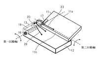
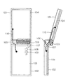
図1(B)に示す第2例は、上記第1例を変形し、両開き構造において第二筐体52に対して第一筐体51及び第三筐体53が回動するいわゆる逆ヒンジ構造としたものである。この第2例では、第一筐体11と第二筐体12との間に、ヒンジ部を内蔵した第三筐体13を備え、第一筐体11には第一回路基板14が設けられ、第二筐体12には第二回路基板15が設けられている。そして、第二筐体12の第三筐体13側の基端部に、図示した状態のように筐体を長手方向に開閉させるための、筐体の短手方向に沿った第一回動軸を持つ第一ヒンジ部16が設けられ、第三筐体13には、筐体を短手方向に開閉させるための、筐体の長手方向に沿った第二回動軸を持つ第二ヒンジ部17が設けられている。第一ヒンジ部16は、第二筐体12と第三筐体13とを連結しており、第二筐体12に対して前記第一回動軸を中心に第一筐体11及び第三筐体13を回動可能にするものである。第二ヒンジ部17は、導電性部材で構成され、第一筐体11と第三筐体13とを連結しており、前記第二回動軸を中心に第二筐体12及び第三筐体13に対して第一筐体11を回動可能にするものである。ここで、図1(B)の側面図において、第一ヒンジ部16は第二筐体12の長手方向延長線上に沿って配置し、第二ヒンジ部17は第一筐体11の長手方向延長線上に沿って配置している。
The second example shown in FIG. 1 (B) is a so-called reverse hinge structure in which the
この場合、第三筐体13内にアンテナ素子18を実装したアンテナ基板19が設けられ、このアンテナ基板19に整合回路21が設けられる。そして、アンテナ素子18は給電部20に接続され、整合回路21とRFケーブル29を介して、第二回路基板15に搭載された無線回路22と接続されている。整合回路21のグランドは、接続部材24を介して導電性部材で構成された第二ヒンジ部17に接続され、この第二ヒンジ部17は第一筐体11内の第一回路基板14と接続されており、第二ヒンジ部17がアンテナ素子18のグランドとして機能している。また、信号の入出力等のための接続ケーブル23が第二ヒンジ部17の内部を挿通して設けられ、この接続ケーブル23によって第一回路基板14と第二回路基板15とが電気的に接続されている。接続ケーブル23は、複数の細線同軸等により構成され、第一回路基板14と第二回路基板15との間において、回路を機能させる信号線とグランドとをそれぞれ接続している。
In this case, an
図2は、図1(B)の構成において、第二ヒンジ部を軸芯として第一筐体を筐体の短手方向に開いたときの状態を示したものである。筐体短手方向において第二ヒンジ部側の端部である第一筐体11bは第二筐体12に近接しているが、筐体短手方向において第二ヒンジ部と反対側の端部である第一筐体11aは第二筐体12から離隔される。この構造制約のため、接続ケーブル23は第一筐体11b近傍で、第一筐体11と第三筐体13を連結する第二ヒンジ部17内部を挿通する必要がある。また、第一ヒンジ部16と第二ヒンジ部17は筐体小型化のため、筐体短手方向の両端に配置される。この構造制約のため、RFケーブル29と接続ケーブル23は第一ヒンジ部16と第二ヒンジ部17の間の限定された空間に配置する必要がある。また、アンテナ素子の体積を大きくし、かつ、RFケーブルの長さを短くするほどアンテナ性能向上を見込めることと、さらに、RFケーブルの引き回しが困難であることなどの理由から、給電部20は第二ヒンジ部17及び接続ケーブル23の近傍に配置する制約が発生する。このように、給電部20は第二ヒンジ部17と接続ケーブル23のグランド近傍に配置されるため、従来の筐体ダイポールアンテナ構成とは異なる。
FIG. 2 shows a state when the first casing is opened in the lateral direction of the casing with the second hinge portion as an axis in the configuration of FIG. The
図3は図1に示した携帯無線装置の構成例における動作時の電流を模式的に示した図であり、図3(A)は第1例における電流の状態を、図3(B)は第2例における電流の状態をそれぞれ示したものである。ここで、矢印は電流の流れる方向を概ね表しており、互いに逆向きの場合、逆位相であることを示す。 3 is a diagram schematically showing the current during operation in the configuration example of the portable wireless device shown in FIG. 1. FIG. 3 (A) shows the current state in the first example, and FIG. The current states in the second example are respectively shown. Here, the arrows generally represent the direction of current flow, and when they are opposite to each other, they indicate an opposite phase.
図3(A)に示すように、第1例の構成の場合は、アンテナ素子58において電流65が流れるとともに、このアンテナ素子58が第一ヒンジ部56及び第一回路基板54と容量結合することにより、第一筐体11内の第一回路基板54において電流66が流れる。また、アンテナ素子58に接続される整合回路61のグランドから第二回路基板55のグランドへ電流67が流れる。第1例の構成では、アンテナ素子58が第二筐体52内に配置されるため、アンテナ素子58の給電部60の位置を比較的自由に設定でき、給電部60を接続ケーブル63から離して配置することが可能である。このため、アンテナ素子58は接続ケーブル63において流れる電流68の影響を受けにくく、高い放射効率を得ることができる。また、第二ヒンジ部57はアンテナ素子58と電気的、物理的に接続されていないため、第二ヒンジ部57による影響も少ない。
As shown in FIG. 3A, in the case of the configuration of the first example, a current 65 flows in the
一方、図3(B)に示すように、第2例の構成の場合は、アンテナ素子18においてエレメント電流25が流れ、このアンテナ素子18の給電部20に接続される整合回路21のグランドから接続部材24、第二ヒンジ部17を通り、第一筐体11内の第一回路基板14のグランドへ電流27が流れる。また、接続ケーブル23において第一回路基板14から第二回路基板15へ電流18が流れる。この第2例の構成では、アンテナ素子18が第三筐体13内に配置されており、図2で前述した、第一ヒンジ部16、第二ヒンジ部17、アンテナ素子18、及び給電部20の位置が限定されるという構造上の制約がある。アンテナ素子18が配置される第三筐体13が第二筐体12に対して回動するため、アンテナ素子18の給電部20は、第二ヒンジ部17から離れた位置に設定することができず、接続ケーブル23や第二ヒンジ部17の近傍に配置せざるを得ない。このため、接続ケーブル23及び第二ヒンジ部17の影響を受けやすい。また、接続ケーブル23において第一回路基板14から第二回路基板15へ流れる電流28と、第二ヒンジ部17から第一回路基板14へ流れる電流27とが逆位相となり、電流がキャンセルされるため、放射効率が低下する。また、整合回路21のグランドである第二ヒンジ部17の内部を異なるインピーダンスをもつ接続ケーブル23が挿通するので、互いの電流が影響しやすい。
On the other hand, as shown in FIG. 3B, in the case of the configuration of the second example, an element current 25 flows in the
そこで、本実施形態では、上記第2例のような筐体構成において特性を改善するために、以下のような構成要素を備えるものとする。図4は本発明の実施形態に係る携帯無線装置の構成を示す図である。なお、図1(B)と同様の構成要素については同一の符号を付している。 Therefore, in this embodiment, in order to improve the characteristics in the case configuration as in the second example, the following components are provided. FIG. 4 is a diagram showing the configuration of the portable radio apparatus according to the embodiment of the present invention. In addition, the same code | symbol is attached | subjected about the component similar to FIG. 1 (B).
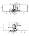
本実施形態では、第一筐体11と第三筐体13を回動可能に連結する第二ヒンジ部17内部の中空部分に、第一筐体11の第一回路基板14と第二筐体12の第二回路基板15との間を接続する接続ケーブル23が挿通する構成となっている。ここで、第二ヒンジ部17は第一筐体11内の第一回路基板14のグランドと接続されており、接続ケーブル23には第一回路基板14と第二回路基板15との間で伝送される信号が流れる。このように複数の筐体を連結するヒンジ部の内部に接続ケーブルが挿通している構成において、中空構造のヒンジ部の内径を接続ケーブルの径に対して十分大きくとるように構成し、ヒンジ部と接続ケーブルとの距離を所定量確保する。具体的には、ヒンジ部と接続ケーブルの導体部との間の容量値が所定値以下となるように、ヒンジ部と接続ケーブルの導体部とを互いに所定の距離以上離して配置される構成とする。これにより、第二ヒンジ部17と接続ケーブル23との電気的な結合が弱くなる。したがって、アンテナ素子18の給電部20から見た接続ケーブル23の影響を軽減でき、高いアンテナ性能を得ることが可能になる。
In the present embodiment, the
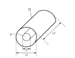
図5は本実施形態のヒンジ部の要部断面を示す図であり、ヒンジ部と接続ケーブルとの寸法関係を示している。接続ケーブル23を構成する導体A31の外径をL1、第二ヒンジ部17を構成する中空部分を有する導体B32の内径をL2とした場合、L1に対してL2が十分大きくなるように構成する。具体的には、相対的に導体B32の内径L2を大きくするか、導体A31の外径L1を小さくする。これにより、導体A31と導体B32との間の容量値を小さくし、第二ヒンジ部17と接続ケーブル23との間の電気的な結合を弱めるようにする。
FIG. 5 is a diagram showing a cross-section of the main part of the hinge part of the present embodiment, showing the dimensional relationship between the hinge part and the connection cable. When the outer diameter of the conductor A31 constituting the
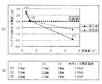
図6はヒンジ部と接続ケーブルとの間の容量値の実施例を示す図であり、図5の導体A31と導体B32との間の容量値設計の具体例を示している。図6(A)は各例の容量値とアンテナ性能(対目標値)の関係を示すグラフであり、図6(B)は各例の寸法及び容量値を示したものである。ここで、L1は図5における導体A31の外径、L2は図5における導体B32の内径、L3は図5における導体B32の長さである。容量値Cは以下の式(1)で求められる。 FIG. 6 is a diagram showing an example of the capacitance value between the hinge portion and the connection cable, and shows a specific example of the capacitance value design between the conductor A31 and the conductor B32 in FIG. FIG. 6A is a graph showing the relationship between the capacitance value of each example and antenna performance (vs. target value), and FIG. 6B shows the size and capacitance value of each example. Here, L1 is the outer diameter of the conductor A31 in FIG. 5, L2 is the inner diameter of the conductor B32 in FIG. 5, and L3 is the length of the conductor B32 in FIG. The capacitance value C is obtained by the following formula (1).
C=εo*εr*(2πL2*L3)/(L2−L1)[F] …(1)
ここで、εo:真空の誘電率[F/m]
εr:比誘電率
L1,L2,L3:長さ[m]
なお、図6(B)に示した導体A〜B間の容量値はεr=1として算出している。
C = εo * εr * (2πL2 * L3) / (L2−L1) [F] (1)
Where εo: dielectric constant of vacuum [F / m]
εr: relative dielectric constant
L1, L2, L3: Length [m]
Note that the capacitance value between the conductors A and B shown in FIG. 6B is calculated as εr = 1.
図6(A)では、アンテナ性能としてL1とL2を変化させたときの800MHz帯における目標値に対するアンテナ性能を示している。導体A〜B間の容量値を小さくするほど、筐体を開いた状態でのアンテナ性能は高くなる。例<1>は、L1=1.8mm、L2=2.0mm、L3=14mmとしたもので、このときの容量値はC=7.01pFであり、送信帯において目標値に対し約6dB低い状態である。 FIG. 6A shows the antenna performance with respect to the target value in the 800 MHz band when L1 and L2 are changed as the antenna performance. The smaller the capacitance value between the conductors A and B, the higher the antenna performance with the housing open. In example <1>, L1 = 1.8 mm, L2 = 2.0 mm, and L3 = 14 mm. At this time, the capacitance value is C = 7.01 pF, which is about 6 dB lower than the target value in the transmission band. State.
そこで、導体A〜導体B間の容量値をできるだけ小さくするために、例<2>はL2を2.0mm→3.1mmとして導体B32の内径L2を大きくしたもので、このときの容量値はC=1.08pFである。また、例<3>はL1を1.8mm→0.8mmとして導体A31の外径L1を小さくしたもので、このときの容量値はC=0.55pFである。図6(A)に示すように、例<2>、<3>共にアンテナ性能を改善でき、目標値を達成できている。この場合、例<3>の方が容量値がより小さくなり、より高い効果が得られた。ここで、少なくとも例<2>の容量値より小さければ、本実施例で設定している目標値を満足でき、例<2>、<3>いずれの方法でもアンテナ性能改善の効果が得られる。 Therefore, in order to make the capacitance value between the conductor A and the conductor B as small as possible, the example <2> increases L2 from 2.0 mm to 3.1 mm and increases the inner diameter L2 of the conductor B32. C = 1.08 pF. In example <3>, the outer diameter L1 of the conductor A31 is reduced by changing L1 from 1.8 mm to 0.8 mm, and the capacitance value at this time is C = 0.55 pF. As shown in FIG. 6A, the antenna performance can be improved and the target value can be achieved in both examples <2> and <3>. In this case, the capacity value of Example <3> was smaller, and a higher effect was obtained. Here, if it is at least smaller than the capacity value of the example <2>, the target value set in the present embodiment can be satisfied, and the effect of improving the antenna performance can be obtained by any of the methods <2> and <3>.
図7は本発明の第2の実施形態に係る携帯無線装置の構成を示す図である。なお、図4と同様の構成要素については同一の符号を付している。第2の実施形態は、同軸ケーブルからなる接続ケーブルの外導体部とグランドとの間に、集中定数Lを形成するインダクタを含む所定インピーダンスを有するインピーダンス素子を設けたものである。図7の構成では、接続ケーブル23の第一筐体11側の第二ヒンジ部17出口近傍において、ケーブルの外導体部と第二ヒンジ部17のグランドとの間にインピーダンス素子35が配置されている。このように、接続ケーブルとグランドとの間に集中定数Lを挿入することによって、接続ケーブルとヒンジ部との間の容量Cと集中定数LとによってLC共振回路が構成される。なお、インピーダンス素子35は、接続ケーブル23の外導体部と第二ヒンジ部17のグランドとの間に設ける構成に限らず、接続ケーブル23の外導体部と第一回路基板14のグランドとの間に設けるような構成としても良い。
FIG. 7 is a diagram showing a configuration of a portable radio apparatus according to the second embodiment of the present invention. In addition, the same code | symbol is attached | subjected about the component similar to FIG. In the second embodiment, an impedance element having a predetermined impedance including an inductor that forms a lumped constant L is provided between an outer conductor portion of a connection cable made of a coaxial cable and a ground. In the configuration of FIG. 7, the
このように接続ケーブルとグランドとの間にインピーダンス素子を設けることで、接続ケーブルとヒンジ部との間の容量が十分小さくできない場合であっても、LC共振によって所望のアンテナ性能改善効果を得ることができる。 By providing an impedance element between the connection cable and the ground in this way, even if the capacity between the connection cable and the hinge portion cannot be sufficiently reduced, a desired antenna performance improvement effect can be obtained by LC resonance. Can do.
上述したように、本実施形態によれば、第二ヒンジ部17と接続ケーブル23とが所定の距離を保つように配置し、両者間の容量が所定値以下となるようにして電気的な結合を弱めることにより、アンテナ性能を向上させることができる。特に、構造上の制約によって第二ヒンジ部17のグランドとアンテナ素子18の給電部20とが近接して配置された場合に、筐体を開いた状態でダイポール動作させた際の、ヒンジ部のグランドやアンテナ素子の給電部に対する接続ケーブルの影響を軽減でき、高いアンテナ性能を得ることができる。
As described above, according to the present embodiment, the
なお、本発明は上記の実施形態において示されたものに限定されるものではなく、明細書の記載、並びに周知の技術に基づいて、当業者が変更、応用することも本発明の予定するところであり、保護を求める範囲に含まれる。 It should be noted that the present invention is not limited to those shown in the above-described embodiments, and those skilled in the art can also make changes and applications based on the description in the specification and well-known techniques. Yes, included in the scope of protection.
上述した実施形態では、第一ヒンジ部と第二ヒンジ部の2つのヒンジ部を有し、第一筐体と第二筐体との間に第三筐体を備える構成について説明したが、これに限定されるものではなく、少なくとも1つのヒンジ部を備えた構成において同様に適用可能である。例えば、2つの筐体を有し、これら2つの筐体を接続するヒンジ部内に接続ケーブルが挿通している構造においても、本実施形態の構成を適用することで同様な効果が得られる。また、2つのヒンジ部を有する両開き構造において、図1(A)に示した一般的なヒンジ構造と図1(B)に示した逆ヒンジ構造のいずれにも適用可能である。 In the above-described embodiment, the configuration in which the first hinge portion and the second hinge portion are provided and the third housing is provided between the first housing and the second housing has been described. However, the present invention is not limited to this, and can be similarly applied to a configuration including at least one hinge portion. For example, a similar effect can be obtained by applying the configuration of this embodiment even in a structure in which two housings are provided and a connection cable is inserted through a hinge portion that connects these two housings. In addition, the double-open structure having two hinge portions can be applied to both the general hinge structure shown in FIG. 1 (A) and the reverse hinge structure shown in FIG. 1 (B).
本発明は、導電性のヒンジ部内部に筐体間を接続する接続ケーブルが挿通する構成とした場合に、アンテナ性能を改善することが可能となる効果を有し、折り畳み可能な筐体内にアンテナを搭載した携帯無線装置等として有用である。 The present invention has an effect that the antenna performance can be improved when the connection cable for connecting between the casings is inserted into the inside of the conductive hinge portion, and the antenna is installed in the foldable casing. It is useful as a portable wireless device equipped with
11 第一筐体
12 第二筐体
13 第三筐体
14 第一回路基板
15 第二回路基板
16 第一ヒンジ部
17 第二ヒンジ部
18 アンテナ素子
19 アンテナ基板
20 給電部
21 整合回路
22 無線回路
23 接続ケーブル
24 接続部材
29 RFケーブル
31 導体A
32 導体B
35 インピーダンス素子
DESCRIPTION OF
32 Conductor B
35 Impedance element
Claims (5)
前記第一筐体内に設けられる第一回路基板と、
第二筐体と、
前記第二筐体内に設けられる第二回路基板と、
前記第一回路基板または前記第二回路基板のいずれか一方に設けられた無線回路と、
前記無線回路に接続されるアンテナ素子と、
前記第一筐体と前記第二筐体を回動可能に連結し、導電性部材で構成され、内部が中空のヒンジ部と、
前記ヒンジ部内を挿通され、前記第一回路基板と前記第二回路基板を電気的に接続する接続ケーブルと、を備え、
前記ヒンジ部がグランドと接続されて前記アンテナ素子のグランドとして機能し、
前記ヒンジ部と前記接続ケーブルの導体部とが所定の距離を保って配置される携帯無線装置。 A first housing;
A first circuit board provided in the first housing;
A second housing;
A second circuit board provided in the second housing;
A radio circuit provided on either the first circuit board or the second circuit board;
An antenna element connected to the radio circuit;
The first housing and the second housing are rotatably connected, and are composed of a conductive member.
A connection cable inserted through the hinge portion and electrically connecting the first circuit board and the second circuit board;
The hinge part is connected to the ground and functions as the ground of the antenna element,
A portable radio apparatus in which the hinge part and the conductor part of the connection cable are arranged at a predetermined distance.
前記第一筐体内に設けられる第一回路基板と、
第二筐体と、
前記第二筐体内に設けられる第二回路基板と、
前記第一回路基板または前記第二回路基板のいずれか一方に設けられた無線回路と、
前記無線回路に接続されるアンテナ素子と、
前記第一筐体と前記第二筐体との間に設けられた第三の筐体と、
前記第一筐体と第三筐体を第一回動軸を中心に回動可能に連結する第一ヒンジ部と、
前記第二筐体と第三筐体を前記第一回動軸と垂直な第二回動軸を中心に回動可能に連結し、導電性部材で構成され、内部が中空の第二ヒンジ部と、
前記第二ヒンジ部内に挿通され、前記第一回路基板と前記第二回路基板を電気的に接続する接続ケーブルと、を備え、
前記第二ヒンジ部がグランドと接続されて前記アンテナ素子のグランドとして機能し、
前記第二ヒンジ部と前記接続ケーブルの導体部とが所定の距離を保って配置される携帯無線装置。 A first housing;
A first circuit board provided in the first housing;
A second housing;
A second circuit board provided in the second housing;
A radio circuit provided on either the first circuit board or the second circuit board;
An antenna element connected to the radio circuit;
A third housing provided between the first housing and the second housing;
A first hinge portion for connecting the first housing and the third housing so as to be rotatable about a first rotation axis;
The second casing and the third casing are connected to each other so as to be rotatable about a second rotation axis perpendicular to the first rotation axis, and are constituted by a conductive member, and the second hinge part having a hollow inside When,
A connection cable that is inserted into the second hinge portion and electrically connects the first circuit board and the second circuit board;
The second hinge part is connected to the ground and functions as the ground of the antenna element,
A portable radio apparatus in which the second hinge part and the conductor part of the connection cable are arranged at a predetermined distance.
前記アンテナ素子は前記第三筐体内に配置され、前記第三筐体内において前記アンテナ素子と前記第二ヒンジ部とが整合回路を介して接続されている携帯無線装置。 The portable wireless device according to claim 2,
The portable wireless device, wherein the antenna element is disposed in the third housing, and the antenna element and the second hinge portion are connected via a matching circuit in the third housing.
前記第二ヒンジ部と前記接続ケーブルの導体部との間の容量値が所定値以下となるように、前記第二ヒンジ部と前記接続ケーブルの導体部とは互いに所定の距離以上離して配置される携帯無線装置。 The portable wireless device according to claim 2,
The second hinge part and the conductor part of the connection cable are spaced apart from each other by a predetermined distance or more so that the capacitance value between the second hinge part and the conductor part of the connection cable is a predetermined value or less. Portable wireless device.
前記接続ケーブルは同軸ケーブルを有して構成され、この同軸ケーブルの外導体部とグランドとの間にインダクタを含む所定インピーダンスを有するインピーダンス素子を備える携帯無線装置。 The portable wireless device according to any one of claims 2 to 4,
The portable wireless device includes an impedance element having a predetermined impedance including an inductor between an outer conductor portion of the coaxial cable and a ground.
Priority Applications (2)
| Application Number | Priority Date | Filing Date | Title |
|---|---|---|---|
| JP2008317204A JP2010141712A (en) | 2008-12-12 | 2008-12-12 | Mobile wireless unit |
| PCT/JP2009/003001 WO2010067480A1 (en) | 2008-12-12 | 2009-06-29 | Mobile wireless unit |
Applications Claiming Priority (1)
| Application Number | Priority Date | Filing Date | Title |
|---|---|---|---|
| JP2008317204A JP2010141712A (en) | 2008-12-12 | 2008-12-12 | Mobile wireless unit |
Publications (1)
| Publication Number | Publication Date |
|---|---|
| JP2010141712A true JP2010141712A (en) | 2010-06-24 |
Family
ID=42242480
Family Applications (1)
| Application Number | Title | Priority Date | Filing Date |
|---|---|---|---|
| JP2008317204A Withdrawn JP2010141712A (en) | 2008-12-12 | 2008-12-12 | Mobile wireless unit |
Country Status (2)
| Country | Link |
|---|---|
| JP (1) | JP2010141712A (en) |
| WO (1) | WO2010067480A1 (en) |
Families Citing this family (1)
| Publication number | Priority date | Publication date | Assignee | Title |
|---|---|---|---|---|
| WO2018116599A1 (en) * | 2016-12-22 | 2018-06-28 | ソニー株式会社 | Electronic device |
Family Cites Families (11)
| Publication number | Priority date | Publication date | Assignee | Title |
|---|---|---|---|---|
| JPS641315A (en) * | 1987-06-24 | 1989-01-05 | Yagi Antenna Co Ltd | Cage antenna with guy |
| JP2002027066A (en) * | 2000-07-06 | 2002-01-25 | Nec Saitama Ltd | Folding portable radio equipment |
| JP2003110673A (en) * | 2001-09-28 | 2003-04-11 | Sanyo Electric Co Ltd | Foldable mobile phone |
| JP2004134976A (en) * | 2002-10-09 | 2004-04-30 | Matsushita Electric Ind Co Ltd | Communication terminal |
| JP2004134975A (en) * | 2002-10-09 | 2004-04-30 | Matsushita Electric Ind Co Ltd | Communication terminal |
| JP4469200B2 (en) * | 2004-03-22 | 2010-05-26 | 富士通株式会社 | Electronic device and portable terminal device |
| JP4358084B2 (en) * | 2004-07-12 | 2009-11-04 | パナソニック株式会社 | Foldable portable radio |
| EP1806907A4 (en) * | 2004-10-28 | 2007-11-07 | Matsushita Electric Ind Co Ltd | Portable telephone with broadcast receiver |
| JP4176756B2 (en) * | 2005-10-26 | 2008-11-05 | モレックス インコーポレーテッド | Electric wire support device |
| JP4447547B2 (en) * | 2005-11-18 | 2010-04-07 | 京セラ株式会社 | Portable electronic devices |
| JP4828937B2 (en) * | 2005-12-27 | 2011-11-30 | 京セラ株式会社 | Wireless terminal device |
-
2008
- 2008-12-12 JP JP2008317204A patent/JP2010141712A/en not_active Withdrawn
-
2009
- 2009-06-29 WO PCT/JP2009/003001 patent/WO2010067480A1/en active Application Filing
Also Published As
| Publication number | Publication date |
|---|---|
| WO2010067480A1 (en) | 2010-06-17 |
Similar Documents
| Publication | Publication Date | Title |
|---|---|---|
| JP4354952B2 (en) | Antenna for portable communication device having hinge | |
| JP4948177B2 (en) | Foldable portable radio | |
| JP3789424B2 (en) | Mobile device | |
| JP4636456B2 (en) | Wireless device | |
| CN1965561A (en) | Folding portable wireless apparatus | |
| JP4661180B2 (en) | Portable wireless terminal and antenna current grounding method | |
| WO2009150768A1 (en) | Portable wireless machine | |
| JP3654430B2 (en) | Antenna device for portable terminal | |
| WO2010050164A1 (en) | Portable wireless device | |
| WO2002069442A1 (en) | Portable transceiver antenna | |
| WO2009130881A1 (en) | Mobile radio device | |
| WO2009095977A1 (en) | Slidable portable terminal | |
| CN102204010A (en) | Mobile wireless equipment | |
| WO2009139100A1 (en) | Portable wireless device | |
| JP4894740B2 (en) | Portable wireless device and wireless communication method | |
| WO2010067480A1 (en) | Mobile wireless unit | |
| JP2006279530A (en) | Antenna assembly and mobile electronic equipment with same antenna assembly | |
| WO2012004984A1 (en) | Mobile wireless device | |
| JP4853368B2 (en) | Wireless communication device | |
| WO2010146739A1 (en) | Antenna apparatus and mobile radio terminal equipped therewith | |
| JP2006033310A (en) | Wireless apparatus | |
| JP2010109703A (en) | Mobile device | |
| JP2006166260A (en) | Folding type portable wireless device | |
| JP4243645B1 (en) | Portable radio | |
| JP2004186970A (en) | Portable wireless device |
Legal Events
| Date | Code | Title | Description |
|---|---|---|---|
| A300 | Withdrawal of application because of no request for examination |
Free format text: JAPANESE INTERMEDIATE CODE: A300 Effective date: 20120306 |