JP4355656B2 - System and method for forming metal oxides using metal organic amines and metal organic oxides - Google Patents
System and method for forming metal oxides using metal organic amines and metal organic oxides Download PDFInfo
- Publication number
- JP4355656B2 JP4355656B2 JP2004531530A JP2004531530A JP4355656B2 JP 4355656 B2 JP4355656 B2 JP 4355656B2 JP 2004531530 A JP2004531530 A JP 2004531530A JP 2004531530 A JP2004531530 A JP 2004531530A JP 4355656 B2 JP4355656 B2 JP 4355656B2
- Authority
- JP
- Japan
- Prior art keywords
- substrate
- formula
- layer
- deposition
- precursor
- Prior art date
- Legal status (The legal status is an assumption and is not a legal conclusion. Google has not performed a legal analysis and makes no representation as to the accuracy of the status listed.)
- Expired - Lifetime
Links
- 238000000034 method Methods 0.000 title claims description 93
- 229910052751 metal Inorganic materials 0.000 title claims description 47
- 239000002184 metal Substances 0.000 title claims description 47
- 229910044991 metal oxide Inorganic materials 0.000 title claims description 42
- 150000004706 metal oxides Chemical class 0.000 title claims description 42
- 150000001412 amines Chemical class 0.000 title description 5
- 239000002243 precursor Substances 0.000 claims description 120
- 239000000758 substrate Substances 0.000 claims description 118
- 150000001875 compounds Chemical class 0.000 claims description 116
- 238000000151 deposition Methods 0.000 claims description 57
- 230000008021 deposition Effects 0.000 claims description 50
- 238000000231 atomic layer deposition Methods 0.000 claims description 49
- 239000004065 semiconductor Substances 0.000 claims description 37
- 238000007740 vapor deposition Methods 0.000 claims description 26
- 125000000962 organic group Chemical group 0.000 claims description 23
- 229910052710 silicon Inorganic materials 0.000 claims description 22
- 239000012159 carrier gas Substances 0.000 claims description 21
- XUIMIQQOPSSXEZ-UHFFFAOYSA-N Silicon Chemical compound [Si] XUIMIQQOPSSXEZ-UHFFFAOYSA-N 0.000 claims description 18
- 239000010703 silicon Substances 0.000 claims description 18
- 230000008569 process Effects 0.000 claims description 15
- 230000003647 oxidation Effects 0.000 claims description 14
- 238000007254 oxidation reaction Methods 0.000 claims description 14
- 229910052739 hydrogen Inorganic materials 0.000 claims description 11
- 150000002739 metals Chemical class 0.000 claims description 11
- 239000001257 hydrogen Substances 0.000 claims description 10
- 230000008016 vaporization Effects 0.000 claims description 10
- UFHFLCQGNIYNRP-UHFFFAOYSA-N Hydrogen Chemical compound [H][H] UFHFLCQGNIYNRP-UHFFFAOYSA-N 0.000 claims description 8
- 229910052735 hafnium Inorganic materials 0.000 claims description 6
- 229910052747 lanthanoid Inorganic materials 0.000 claims description 6
- 150000002602 lanthanoids Chemical class 0.000 claims description 6
- 238000009834 vaporization Methods 0.000 claims description 6
- 238000004519 manufacturing process Methods 0.000 claims description 5
- 229910052719 titanium Inorganic materials 0.000 claims description 5
- 229910052782 aluminium Inorganic materials 0.000 claims description 4
- 229910052726 zirconium Inorganic materials 0.000 claims description 4
- 229910052777 Praseodymium Inorganic materials 0.000 claims description 3
- 229910052746 lanthanum Inorganic materials 0.000 claims description 3
- 229910052758 niobium Inorganic materials 0.000 claims description 3
- 229910052715 tantalum Inorganic materials 0.000 claims description 3
- 229910052727 yttrium Inorganic materials 0.000 claims description 3
- 229910052688 Gadolinium Inorganic materials 0.000 claims description 2
- 229910052779 Neodymium Inorganic materials 0.000 claims description 2
- 239000010410 layer Substances 0.000 description 130
- 238000005229 chemical vapour deposition Methods 0.000 description 44
- 239000003990 capacitor Substances 0.000 description 36
- 239000013626 chemical specie Substances 0.000 description 25
- 239000007789 gas Substances 0.000 description 22
- 230000004888 barrier function Effects 0.000 description 20
- 239000000463 material Substances 0.000 description 20
- 239000002356 single layer Substances 0.000 description 14
- 229910052760 oxygen Inorganic materials 0.000 description 13
- QVGXLLKOCUKJST-UHFFFAOYSA-N atomic oxygen Chemical compound [O] QVGXLLKOCUKJST-UHFFFAOYSA-N 0.000 description 12
- 238000006243 chemical reaction Methods 0.000 description 12
- 239000001301 oxygen Substances 0.000 description 12
- 235000012431 wafers Nutrition 0.000 description 12
- 239000000126 substance Substances 0.000 description 10
- VYPSYNLAJGMNEJ-UHFFFAOYSA-N Silicium dioxide Chemical compound O=[Si]=O VYPSYNLAJGMNEJ-UHFFFAOYSA-N 0.000 description 9
- 125000000217 alkyl group Chemical group 0.000 description 9
- 239000010408 film Substances 0.000 description 9
- 229910021420 polycrystalline silicon Inorganic materials 0.000 description 9
- 229920005591 polysilicon Polymers 0.000 description 9
- 239000007787 solid Substances 0.000 description 9
- 238000000137 annealing Methods 0.000 description 8
- 239000012495 reaction gas Substances 0.000 description 8
- 238000010926 purge Methods 0.000 description 7
- 239000010936 titanium Substances 0.000 description 7
- IJGRMHOSHXDMSA-UHFFFAOYSA-N Atomic nitrogen Chemical compound N#N IJGRMHOSHXDMSA-UHFFFAOYSA-N 0.000 description 6
- 238000009792 diffusion process Methods 0.000 description 6
- -1 electrodes Substances 0.000 description 6
- 239000007788 liquid Substances 0.000 description 6
- 230000001590 oxidative effect Effects 0.000 description 6
- 229920006395 saturated elastomer Polymers 0.000 description 6
- 229910004298 SiO 2 Inorganic materials 0.000 description 5
- 125000001931 aliphatic group Chemical group 0.000 description 5
- 230000015572 biosynthetic process Effects 0.000 description 5
- 239000004020 conductor Substances 0.000 description 5
- 239000003989 dielectric material Substances 0.000 description 5
- 125000001183 hydrocarbyl group Chemical group 0.000 description 5
- 235000012239 silicon dioxide Nutrition 0.000 description 5
- 239000010409 thin film Substances 0.000 description 5
- XKRFYHLGVUSROY-UHFFFAOYSA-N Argon Chemical compound [Ar] XKRFYHLGVUSROY-UHFFFAOYSA-N 0.000 description 4
- 150000004703 alkoxides Chemical class 0.000 description 4
- 125000003118 aryl group Chemical group 0.000 description 4
- 210000004027 cell Anatomy 0.000 description 4
- 125000004122 cyclic group Chemical group 0.000 description 4
- 238000001704 evaporation Methods 0.000 description 4
- 229930195733 hydrocarbon Natural products 0.000 description 4
- 150000002430 hydrocarbons Chemical class 0.000 description 4
- 239000000203 mixture Substances 0.000 description 4
- 229910052757 nitrogen Inorganic materials 0.000 description 4
- 239000000376 reactant Substances 0.000 description 4
- 239000012713 reactive precursor Substances 0.000 description 4
- 239000000377 silicon dioxide Substances 0.000 description 4
- 239000002904 solvent Substances 0.000 description 4
- 125000001424 substituent group Chemical group 0.000 description 4
- OKTJSMMVPCPJKN-UHFFFAOYSA-N Carbon Chemical compound [C] OKTJSMMVPCPJKN-UHFFFAOYSA-N 0.000 description 3
- 229910052786 argon Inorganic materials 0.000 description 3
- 125000004429 atom Chemical group 0.000 description 3
- 229910052799 carbon Inorganic materials 0.000 description 3
- 238000000354 decomposition reaction Methods 0.000 description 3
- 238000005516 engineering process Methods 0.000 description 3
- 125000001495 ethyl group Chemical group [H]C([H])([H])C([H])([H])* 0.000 description 3
- 229910052734 helium Inorganic materials 0.000 description 3
- 239000012705 liquid precursor Substances 0.000 description 3
- 125000002496 methyl group Chemical group [H]C([H])([H])* 0.000 description 3
- 229910003455 mixed metal oxide Inorganic materials 0.000 description 3
- 239000003960 organic solvent Substances 0.000 description 3
- BASFCYQUMIYNBI-UHFFFAOYSA-N platinum Chemical compound [Pt] BASFCYQUMIYNBI-UHFFFAOYSA-N 0.000 description 3
- 238000012545 processing Methods 0.000 description 3
- 238000001179 sorption measurement Methods 0.000 description 3
- 125000000999 tert-butyl group Chemical group [H]C([H])([H])C(*)(C([H])([H])[H])C([H])([H])[H] 0.000 description 3
- XLYOFNOQVPJJNP-UHFFFAOYSA-N water Substances O XLYOFNOQVPJJNP-UHFFFAOYSA-N 0.000 description 3
- 229910018072 Al 2 O 3 Inorganic materials 0.000 description 2
- QGZKDVFQNNGYKY-UHFFFAOYSA-N Ammonia Chemical compound N QGZKDVFQNNGYKY-UHFFFAOYSA-N 0.000 description 2
- 239000004215 Carbon black (E152) Substances 0.000 description 2
- RTZKZFJDLAIYFH-UHFFFAOYSA-N Diethyl ether Chemical compound CCOCC RTZKZFJDLAIYFH-UHFFFAOYSA-N 0.000 description 2
- 238000004833 X-ray photoelectron spectroscopy Methods 0.000 description 2
- 125000002723 alicyclic group Chemical group 0.000 description 2
- 125000003342 alkenyl group Chemical group 0.000 description 2
- 150000003973 alkyl amines Chemical class 0.000 description 2
- 125000000304 alkynyl group Chemical group 0.000 description 2
- 238000013459 approach Methods 0.000 description 2
- 230000000712 assembly Effects 0.000 description 2
- 238000000429 assembly Methods 0.000 description 2
- 238000003877 atomic layer epitaxy Methods 0.000 description 2
- 239000005380 borophosphosilicate glass Substances 0.000 description 2
- 239000006227 byproduct Substances 0.000 description 2
- 239000011203 carbon fibre reinforced carbon Substances 0.000 description 2
- 238000000576 coating method Methods 0.000 description 2
- 238000007796 conventional method Methods 0.000 description 2
- 238000005137 deposition process Methods 0.000 description 2
- 229910052731 fluorine Inorganic materials 0.000 description 2
- 238000010574 gas phase reaction Methods 0.000 description 2
- 239000011521 glass Substances 0.000 description 2
- 239000001307 helium Substances 0.000 description 2
- SWQJXJOGLNCZEY-UHFFFAOYSA-N helium atom Chemical compound [He] SWQJXJOGLNCZEY-UHFFFAOYSA-N 0.000 description 2
- 125000000623 heterocyclic group Chemical group 0.000 description 2
- 125000004435 hydrogen atom Chemical group [H]* 0.000 description 2
- 238000011065 in-situ storage Methods 0.000 description 2
- 229910052741 iridium Inorganic materials 0.000 description 2
- 238000004518 low pressure chemical vapour deposition Methods 0.000 description 2
- 229910001510 metal chloride Inorganic materials 0.000 description 2
- 229910052752 metalloid Inorganic materials 0.000 description 2
- 150000002738 metalloids Chemical class 0.000 description 2
- 238000004377 microelectronic Methods 0.000 description 2
- 238000002156 mixing Methods 0.000 description 2
- 230000004048 modification Effects 0.000 description 2
- 238000012986 modification Methods 0.000 description 2
- 238000001451 molecular beam epitaxy Methods 0.000 description 2
- 230000000737 periodic effect Effects 0.000 description 2
- 238000000623 plasma-assisted chemical vapour deposition Methods 0.000 description 2
- 229910052697 platinum Inorganic materials 0.000 description 2
- 125000001436 propyl group Chemical group [H]C([*])([H])C([H])([H])C([H])([H])[H] 0.000 description 2
- 229910052703 rhodium Inorganic materials 0.000 description 2
- 239000010948 rhodium Substances 0.000 description 2
- 229910052707 ruthenium Inorganic materials 0.000 description 2
- 229930195734 saturated hydrocarbon Natural products 0.000 description 2
- 229910021332 silicide Inorganic materials 0.000 description 2
- 239000000243 solution Substances 0.000 description 2
- 230000003068 static effect Effects 0.000 description 2
- 229910052718 tin Inorganic materials 0.000 description 2
- 229910052723 transition metal Inorganic materials 0.000 description 2
- 150000003624 transition metals Chemical class 0.000 description 2
- 229910052721 tungsten Inorganic materials 0.000 description 2
- 230000005641 tunneling Effects 0.000 description 2
- JBRZTFJDHDCESZ-UHFFFAOYSA-N AsGa Chemical compound [As]#[Ga] JBRZTFJDHDCESZ-UHFFFAOYSA-N 0.000 description 1
- 229910052684 Cerium Inorganic materials 0.000 description 1
- ZAMOUSCENKQFHK-UHFFFAOYSA-N Chlorine atom Chemical compound [Cl] ZAMOUSCENKQFHK-UHFFFAOYSA-N 0.000 description 1
- PXGOKWXKJXAPGV-UHFFFAOYSA-N Fluorine Chemical group FF PXGOKWXKJXAPGV-UHFFFAOYSA-N 0.000 description 1
- 229910001218 Gallium arsenide Inorganic materials 0.000 description 1
- 229910021193 La 2 O 3 Inorganic materials 0.000 description 1
- WHXSMMKQMYFTQS-UHFFFAOYSA-N Lithium Chemical compound [Li] WHXSMMKQMYFTQS-UHFFFAOYSA-N 0.000 description 1
- 229910019899 RuO Inorganic materials 0.000 description 1
- KJTLSVCANCCWHF-UHFFFAOYSA-N Ruthenium Chemical compound [Ru] KJTLSVCANCCWHF-UHFFFAOYSA-N 0.000 description 1
- 229910052581 Si3N4 Inorganic materials 0.000 description 1
- 229910002367 SrTiO Inorganic materials 0.000 description 1
- NINIDFKCEFEMDL-UHFFFAOYSA-N Sulfur Chemical compound [S] NINIDFKCEFEMDL-UHFFFAOYSA-N 0.000 description 1
- 229910004166 TaN Inorganic materials 0.000 description 1
- 229910010413 TiO 2 Inorganic materials 0.000 description 1
- ATJFFYVFTNAWJD-UHFFFAOYSA-N Tin Chemical compound [Sn] ATJFFYVFTNAWJD-UHFFFAOYSA-N 0.000 description 1
- NRTOMJZYCJJWKI-UHFFFAOYSA-N Titanium nitride Chemical compound [Ti]#N NRTOMJZYCJJWKI-UHFFFAOYSA-N 0.000 description 1
- QCWXUUIWCKQGHC-UHFFFAOYSA-N Zirconium Chemical compound [Zr] QCWXUUIWCKQGHC-UHFFFAOYSA-N 0.000 description 1
- 229910052768 actinide Inorganic materials 0.000 description 1
- 150000001255 actinides Chemical class 0.000 description 1
- 230000009471 action Effects 0.000 description 1
- 150000001298 alcohols Chemical class 0.000 description 1
- 238000006136 alcoholysis reaction Methods 0.000 description 1
- 125000003545 alkoxy group Chemical group 0.000 description 1
- 125000002877 alkyl aryl group Chemical group 0.000 description 1
- 150000001343 alkyl silanes Chemical class 0.000 description 1
- 125000004390 alkyl sulfonyl group Chemical group 0.000 description 1
- 229910045601 alloy Inorganic materials 0.000 description 1
- 239000000956 alloy Substances 0.000 description 1
- 230000004075 alteration Effects 0.000 description 1
- XAGFODPZIPBFFR-UHFFFAOYSA-N aluminium Chemical compound [Al] XAGFODPZIPBFFR-UHFFFAOYSA-N 0.000 description 1
- 150000001408 amides Chemical class 0.000 description 1
- 229910021529 ammonia Inorganic materials 0.000 description 1
- 238000004458 analytical method Methods 0.000 description 1
- 150000004945 aromatic hydrocarbons Chemical class 0.000 description 1
- 125000003710 aryl alkyl group Chemical group 0.000 description 1
- 239000012298 atmosphere Substances 0.000 description 1
- 238000001505 atmospheric-pressure chemical vapour deposition Methods 0.000 description 1
- 230000005587 bubbling Effects 0.000 description 1
- 125000004432 carbon atom Chemical group C* 0.000 description 1
- 125000002915 carbonyl group Chemical group [*:2]C([*:1])=O 0.000 description 1
- 125000004181 carboxyalkyl group Chemical group 0.000 description 1
- 230000008859 change Effects 0.000 description 1
- 238000004871 chemical beam epitaxy Methods 0.000 description 1
- 239000012707 chemical precursor Substances 0.000 description 1
- 239000000460 chlorine Substances 0.000 description 1
- 229910052801 chlorine Inorganic materials 0.000 description 1
- 229910052804 chromium Inorganic materials 0.000 description 1
- 239000011248 coating agent Substances 0.000 description 1
- 238000009833 condensation Methods 0.000 description 1
- 230000005494 condensation Effects 0.000 description 1
- 238000011109 contamination Methods 0.000 description 1
- 230000001186 cumulative effect Effects 0.000 description 1
- 150000001913 cyanates Chemical class 0.000 description 1
- 125000004093 cyano group Chemical group *C#N 0.000 description 1
- 125000000753 cycloalkyl group Chemical group 0.000 description 1
- 230000006866 deterioration Effects 0.000 description 1
- ZYLGGWPMIDHSEZ-UHFFFAOYSA-N dimethylazanide;hafnium(4+) Chemical compound [Hf+4].C[N-]C.C[N-]C.C[N-]C.C[N-]C ZYLGGWPMIDHSEZ-UHFFFAOYSA-N 0.000 description 1
- 150000002148 esters Chemical class 0.000 description 1
- 125000001033 ether group Chemical group 0.000 description 1
- 150000002170 ethers Chemical class 0.000 description 1
- NPEOKFBCHNGLJD-UHFFFAOYSA-N ethyl(methyl)azanide;hafnium(4+) Chemical compound [Hf+4].CC[N-]C.CC[N-]C.CC[N-]C.CC[N-]C NPEOKFBCHNGLJD-UHFFFAOYSA-N 0.000 description 1
- 230000008020 evaporation Effects 0.000 description 1
- 239000000835 fiber Substances 0.000 description 1
- 230000005669 field effect Effects 0.000 description 1
- 239000011737 fluorine Chemical group 0.000 description 1
- 125000001153 fluoro group Chemical group F* 0.000 description 1
- 230000006870 function Effects 0.000 description 1
- 229910052733 gallium Inorganic materials 0.000 description 1
- 238000000171 gas-source molecular beam epitaxy Methods 0.000 description 1
- 229910052732 germanium Inorganic materials 0.000 description 1
- WZVIPWQGBBCHJP-UHFFFAOYSA-N hafnium(4+);2-methylpropan-2-olate Chemical compound [Hf+4].CC(C)(C)[O-].CC(C)(C)[O-].CC(C)(C)[O-].CC(C)(C)[O-] WZVIPWQGBBCHJP-UHFFFAOYSA-N 0.000 description 1
- 125000001188 haloalkyl group Chemical group 0.000 description 1
- 125000005843 halogen group Chemical group 0.000 description 1
- 238000010438 heat treatment Methods 0.000 description 1
- 125000003187 heptyl group Chemical group [H]C([*])([H])C([H])([H])C([H])([H])C([H])([H])C([H])([H])C([H])([H])C([H])([H])[H] 0.000 description 1
- 125000004356 hydroxy functional group Chemical group O* 0.000 description 1
- 125000002768 hydroxyalkyl group Chemical group 0.000 description 1
- 238000007654 immersion Methods 0.000 description 1
- 229910052738 indium Inorganic materials 0.000 description 1
- 230000010354 integration Effects 0.000 description 1
- GKOZUEZYRPOHIO-UHFFFAOYSA-N iridium atom Chemical compound [Ir] GKOZUEZYRPOHIO-UHFFFAOYSA-N 0.000 description 1
- 239000012948 isocyanate Substances 0.000 description 1
- 150000002513 isocyanates Chemical class 0.000 description 1
- 125000001449 isopropyl group Chemical group [H]C([H])([H])C([H])(*)C([H])([H])[H] 0.000 description 1
- 150000002596 lactones Chemical class 0.000 description 1
- 229910052745 lead Inorganic materials 0.000 description 1
- 229910052744 lithium Inorganic materials 0.000 description 1
- 229910052748 manganese Inorganic materials 0.000 description 1
- 239000000155 melt Substances 0.000 description 1
- 230000008018 melting Effects 0.000 description 1
- 238000002844 melting Methods 0.000 description 1
- 150000002736 metal compounds Chemical class 0.000 description 1
- 229910052750 molybdenum Inorganic materials 0.000 description 1
- 229910021421 monocrystalline silicon Inorganic materials 0.000 description 1
- 125000002950 monocyclic group Chemical group 0.000 description 1
- 125000000740 n-pentyl group Chemical group [H]C([H])([H])C([H])([H])C([H])([H])C([H])([H])C([H])([H])* 0.000 description 1
- 125000004123 n-propyl group Chemical group [H]C([H])([H])C([H])([H])C([H])([H])* 0.000 description 1
- 150000004767 nitrides Chemical class 0.000 description 1
- 150000002825 nitriles Chemical class 0.000 description 1
- 125000000449 nitro group Chemical group [O-][N+](*)=O 0.000 description 1
- 125000004971 nitroalkyl group Chemical group 0.000 description 1
- 239000012299 nitrogen atmosphere Substances 0.000 description 1
- 125000004433 nitrogen atom Chemical group N* 0.000 description 1
- QJGQUHMNIGDVPM-UHFFFAOYSA-N nitrogen group Chemical group [N] QJGQUHMNIGDVPM-UHFFFAOYSA-N 0.000 description 1
- 125000002524 organometallic group Chemical group 0.000 description 1
- 239000007800 oxidant agent Substances 0.000 description 1
- 150000002978 peroxides Chemical class 0.000 description 1
- 230000000704 physical effect Effects 0.000 description 1
- 229920000768 polyamine Polymers 0.000 description 1
- 125000005575 polycyclic aromatic hydrocarbon group Chemical group 0.000 description 1
- 229920000570 polyether Polymers 0.000 description 1
- 230000002028 premature Effects 0.000 description 1
- 238000002360 preparation method Methods 0.000 description 1
- 239000000047 product Substances 0.000 description 1
- 238000005086 pumping Methods 0.000 description 1
- 238000004151 rapid thermal annealing Methods 0.000 description 1
- 230000009257 reactivity Effects 0.000 description 1
- 230000009467 reduction Effects 0.000 description 1
- 239000003870 refractory metal Substances 0.000 description 1
- 229910052702 rhenium Inorganic materials 0.000 description 1
- MHOVAHRLVXNVSD-UHFFFAOYSA-N rhodium atom Chemical compound [Rh] MHOVAHRLVXNVSD-UHFFFAOYSA-N 0.000 description 1
- 125000006413 ring segment Chemical group 0.000 description 1
- 229910001925 ruthenium oxide Inorganic materials 0.000 description 1
- WOCIAKWEIIZHES-UHFFFAOYSA-N ruthenium(iv) oxide Chemical compound O=[Ru]=O WOCIAKWEIIZHES-UHFFFAOYSA-N 0.000 description 1
- 229910052594 sapphire Inorganic materials 0.000 description 1
- 239000010980 sapphire Substances 0.000 description 1
- 229910052706 scandium Inorganic materials 0.000 description 1
- 238000000926 separation method Methods 0.000 description 1
- FVBUAEGBCNSCDD-UHFFFAOYSA-N silicide(4-) Chemical compound [Si-4] FVBUAEGBCNSCDD-UHFFFAOYSA-N 0.000 description 1
- 229910052814 silicon oxide Inorganic materials 0.000 description 1
- HWEYZGSCHQNNEH-UHFFFAOYSA-N silicon tantalum Chemical compound [Si].[Ta] HWEYZGSCHQNNEH-UHFFFAOYSA-N 0.000 description 1
- 239000002210 silicon-based material Substances 0.000 description 1
- 229920002545 silicone oil Polymers 0.000 description 1
- 125000005374 siloxide group Chemical group 0.000 description 1
- 239000006104 solid solution Substances 0.000 description 1
- 210000002325 somatostatin-secreting cell Anatomy 0.000 description 1
- 238000004544 sputter deposition Methods 0.000 description 1
- 238000006467 substitution reaction Methods 0.000 description 1
- 125000004964 sulfoalkyl group Chemical group 0.000 description 1
- 239000011593 sulfur Substances 0.000 description 1
- 229910052717 sulfur Inorganic materials 0.000 description 1
- 125000004434 sulfur atom Chemical group 0.000 description 1
- 238000006557 surface reaction Methods 0.000 description 1
- MZLGASXMSKOWSE-UHFFFAOYSA-N tantalum nitride Chemical compound [Ta]#N MZLGASXMSKOWSE-UHFFFAOYSA-N 0.000 description 1
- HSXKFDGTKKAEHL-UHFFFAOYSA-N tantalum(v) ethoxide Chemical compound [Ta+5].CC[O-].CC[O-].CC[O-].CC[O-].CC[O-] HSXKFDGTKKAEHL-UHFFFAOYSA-N 0.000 description 1
- 229910052713 technetium Inorganic materials 0.000 description 1
- LMBFAGIMSUYTBN-MPZNNTNKSA-N teixobactin Chemical compound C([C@H](C(=O)N[C@@H]([C@@H](C)CC)C(=O)N[C@@H](CO)C(=O)N[C@H](CCC(N)=O)C(=O)N[C@H]([C@@H](C)CC)C(=O)N[C@@H]([C@@H](C)CC)C(=O)N[C@@H](CO)C(=O)N[C@H]1C(N[C@@H](C)C(=O)N[C@@H](C[C@@H]2NC(=N)NC2)C(=O)N[C@H](C(=O)O[C@H]1C)[C@@H](C)CC)=O)NC)C1=CC=CC=C1 LMBFAGIMSUYTBN-MPZNNTNKSA-N 0.000 description 1
- MNWRORMXBIWXCI-UHFFFAOYSA-N tetrakis(dimethylamido)titanium Chemical compound CN(C)[Ti](N(C)C)(N(C)C)N(C)C MNWRORMXBIWXCI-UHFFFAOYSA-N 0.000 description 1
- 229910052716 thallium Inorganic materials 0.000 description 1
- 150000003567 thiocyanates Chemical class 0.000 description 1
- 150000003568 thioethers Chemical class 0.000 description 1
- VXUYXOFXAQZZMF-UHFFFAOYSA-N titanium(IV) isopropoxide Chemical compound CC(C)O[Ti](OC(C)C)(OC(C)C)OC(C)C VXUYXOFXAQZZMF-UHFFFAOYSA-N 0.000 description 1
- WFKWXMTUELFFGS-UHFFFAOYSA-N tungsten Chemical compound [W] WFKWXMTUELFFGS-UHFFFAOYSA-N 0.000 description 1
- 239000010937 tungsten Substances 0.000 description 1
- 229930195735 unsaturated hydrocarbon Natural products 0.000 description 1
- 229910052720 vanadium Inorganic materials 0.000 description 1
- 125000000391 vinyl group Chemical group [H]C([*])=C([H])[H] 0.000 description 1
Images

Classifications
-
- C—CHEMISTRY; METALLURGY
- C23—COATING METALLIC MATERIAL; COATING MATERIAL WITH METALLIC MATERIAL; CHEMICAL SURFACE TREATMENT; DIFFUSION TREATMENT OF METALLIC MATERIAL; COATING BY VACUUM EVAPORATION, BY SPUTTERING, BY ION IMPLANTATION OR BY CHEMICAL VAPOUR DEPOSITION, IN GENERAL; INHIBITING CORROSION OF METALLIC MATERIAL OR INCRUSTATION IN GENERAL
- C23C—COATING METALLIC MATERIAL; COATING MATERIAL WITH METALLIC MATERIAL; SURFACE TREATMENT OF METALLIC MATERIAL BY DIFFUSION INTO THE SURFACE, BY CHEMICAL CONVERSION OR SUBSTITUTION; COATING BY VACUUM EVAPORATION, BY SPUTTERING, BY ION IMPLANTATION OR BY CHEMICAL VAPOUR DEPOSITION, IN GENERAL
- C23C16/00—Chemical coating by decomposition of gaseous compounds, without leaving reaction products of surface material in the coating, i.e. chemical vapour deposition [CVD] processes
- C23C16/22—Chemical coating by decomposition of gaseous compounds, without leaving reaction products of surface material in the coating, i.e. chemical vapour deposition [CVD] processes characterised by the deposition of inorganic material, other than metallic material
- C23C16/30—Deposition of compounds, mixtures or solid solutions, e.g. borides, carbides, nitrides
- C23C16/40—Oxides
- C23C16/405—Oxides of refractory metals or yttrium
-
- C—CHEMISTRY; METALLURGY
- C23—COATING METALLIC MATERIAL; COATING MATERIAL WITH METALLIC MATERIAL; CHEMICAL SURFACE TREATMENT; DIFFUSION TREATMENT OF METALLIC MATERIAL; COATING BY VACUUM EVAPORATION, BY SPUTTERING, BY ION IMPLANTATION OR BY CHEMICAL VAPOUR DEPOSITION, IN GENERAL; INHIBITING CORROSION OF METALLIC MATERIAL OR INCRUSTATION IN GENERAL
- C23C—COATING METALLIC MATERIAL; COATING MATERIAL WITH METALLIC MATERIAL; SURFACE TREATMENT OF METALLIC MATERIAL BY DIFFUSION INTO THE SURFACE, BY CHEMICAL CONVERSION OR SUBSTITUTION; COATING BY VACUUM EVAPORATION, BY SPUTTERING, BY ION IMPLANTATION OR BY CHEMICAL VAPOUR DEPOSITION, IN GENERAL
- C23C16/00—Chemical coating by decomposition of gaseous compounds, without leaving reaction products of surface material in the coating, i.e. chemical vapour deposition [CVD] processes
- C23C16/22—Chemical coating by decomposition of gaseous compounds, without leaving reaction products of surface material in the coating, i.e. chemical vapour deposition [CVD] processes characterised by the deposition of inorganic material, other than metallic material
- C23C16/30—Deposition of compounds, mixtures or solid solutions, e.g. borides, carbides, nitrides
- C23C16/40—Oxides
-
- C—CHEMISTRY; METALLURGY
- C23—COATING METALLIC MATERIAL; COATING MATERIAL WITH METALLIC MATERIAL; CHEMICAL SURFACE TREATMENT; DIFFUSION TREATMENT OF METALLIC MATERIAL; COATING BY VACUUM EVAPORATION, BY SPUTTERING, BY ION IMPLANTATION OR BY CHEMICAL VAPOUR DEPOSITION, IN GENERAL; INHIBITING CORROSION OF METALLIC MATERIAL OR INCRUSTATION IN GENERAL
- C23C—COATING METALLIC MATERIAL; COATING MATERIAL WITH METALLIC MATERIAL; SURFACE TREATMENT OF METALLIC MATERIAL BY DIFFUSION INTO THE SURFACE, BY CHEMICAL CONVERSION OR SUBSTITUTION; COATING BY VACUUM EVAPORATION, BY SPUTTERING, BY ION IMPLANTATION OR BY CHEMICAL VAPOUR DEPOSITION, IN GENERAL
- C23C16/00—Chemical coating by decomposition of gaseous compounds, without leaving reaction products of surface material in the coating, i.e. chemical vapour deposition [CVD] processes
- C23C16/44—Chemical coating by decomposition of gaseous compounds, without leaving reaction products of surface material in the coating, i.e. chemical vapour deposition [CVD] processes characterised by the method of coating
- C23C16/455—Chemical coating by decomposition of gaseous compounds, without leaving reaction products of surface material in the coating, i.e. chemical vapour deposition [CVD] processes characterised by the method of coating characterised by the method used for introducing gases into reaction chamber or for modifying gas flows in reaction chamber
- C23C16/45523—Pulsed gas flow or change of composition over time
- C23C16/45525—Atomic layer deposition [ALD]
- C23C16/45527—Atomic layer deposition [ALD] characterized by the ALD cycle, e.g. different flows or temperatures during half-reactions, unusual pulsing sequence, use of precursor mixtures or auxiliary reactants or activations
- C23C16/45531—Atomic layer deposition [ALD] characterized by the ALD cycle, e.g. different flows or temperatures during half-reactions, unusual pulsing sequence, use of precursor mixtures or auxiliary reactants or activations specially adapted for making ternary or higher compositions
-
- C—CHEMISTRY; METALLURGY
- C23—COATING METALLIC MATERIAL; COATING MATERIAL WITH METALLIC MATERIAL; CHEMICAL SURFACE TREATMENT; DIFFUSION TREATMENT OF METALLIC MATERIAL; COATING BY VACUUM EVAPORATION, BY SPUTTERING, BY ION IMPLANTATION OR BY CHEMICAL VAPOUR DEPOSITION, IN GENERAL; INHIBITING CORROSION OF METALLIC MATERIAL OR INCRUSTATION IN GENERAL
- C23C—COATING METALLIC MATERIAL; COATING MATERIAL WITH METALLIC MATERIAL; SURFACE TREATMENT OF METALLIC MATERIAL BY DIFFUSION INTO THE SURFACE, BY CHEMICAL CONVERSION OR SUBSTITUTION; COATING BY VACUUM EVAPORATION, BY SPUTTERING, BY ION IMPLANTATION OR BY CHEMICAL VAPOUR DEPOSITION, IN GENERAL
- C23C16/00—Chemical coating by decomposition of gaseous compounds, without leaving reaction products of surface material in the coating, i.e. chemical vapour deposition [CVD] processes
- C23C16/44—Chemical coating by decomposition of gaseous compounds, without leaving reaction products of surface material in the coating, i.e. chemical vapour deposition [CVD] processes characterised by the method of coating
- C23C16/455—Chemical coating by decomposition of gaseous compounds, without leaving reaction products of surface material in the coating, i.e. chemical vapour deposition [CVD] processes characterised by the method of coating characterised by the method used for introducing gases into reaction chamber or for modifying gas flows in reaction chamber
- C23C16/45523—Pulsed gas flow or change of composition over time
- C23C16/45525—Atomic layer deposition [ALD]
- C23C16/45553—Atomic layer deposition [ALD] characterized by the use of precursors specially adapted for ALD
-
- H—ELECTRICITY
- H01—ELECTRIC ELEMENTS
- H01L—SEMICONDUCTOR DEVICES NOT COVERED BY CLASS H10
- H01L21/00—Processes or apparatus adapted for the manufacture or treatment of semiconductor or solid state devices or of parts thereof
- H01L21/02—Manufacture or treatment of semiconductor devices or of parts thereof
- H01L21/02104—Forming layers
- H01L21/02107—Forming insulating materials on a substrate
- H01L21/02109—Forming insulating materials on a substrate characterised by the type of layer, e.g. type of material, porous/non-porous, pre-cursors, mixtures or laminates
- H01L21/02112—Forming insulating materials on a substrate characterised by the type of layer, e.g. type of material, porous/non-porous, pre-cursors, mixtures or laminates characterised by the material of the layer
- H01L21/02172—Forming insulating materials on a substrate characterised by the type of layer, e.g. type of material, porous/non-porous, pre-cursors, mixtures or laminates characterised by the material of the layer the material containing at least one metal element, e.g. metal oxides, metal nitrides, metal oxynitrides or metal carbides
- H01L21/02175—Forming insulating materials on a substrate characterised by the type of layer, e.g. type of material, porous/non-porous, pre-cursors, mixtures or laminates characterised by the material of the layer the material containing at least one metal element, e.g. metal oxides, metal nitrides, metal oxynitrides or metal carbides characterised by the metal
-
- H—ELECTRICITY
- H01—ELECTRIC ELEMENTS
- H01L—SEMICONDUCTOR DEVICES NOT COVERED BY CLASS H10
- H01L21/00—Processes or apparatus adapted for the manufacture or treatment of semiconductor or solid state devices or of parts thereof
- H01L21/02—Manufacture or treatment of semiconductor devices or of parts thereof
- H01L21/02104—Forming layers
- H01L21/02107—Forming insulating materials on a substrate
- H01L21/02109—Forming insulating materials on a substrate characterised by the type of layer, e.g. type of material, porous/non-porous, pre-cursors, mixtures or laminates
- H01L21/02205—Forming insulating materials on a substrate characterised by the type of layer, e.g. type of material, porous/non-porous, pre-cursors, mixtures or laminates the layer being characterised by the precursor material for deposition
-
- H—ELECTRICITY
- H01—ELECTRIC ELEMENTS
- H01L—SEMICONDUCTOR DEVICES NOT COVERED BY CLASS H10
- H01L21/00—Processes or apparatus adapted for the manufacture or treatment of semiconductor or solid state devices or of parts thereof
- H01L21/02—Manufacture or treatment of semiconductor devices or of parts thereof
- H01L21/02104—Forming layers
- H01L21/02107—Forming insulating materials on a substrate
- H01L21/02225—Forming insulating materials on a substrate characterised by the process for the formation of the insulating layer
- H01L21/0226—Forming insulating materials on a substrate characterised by the process for the formation of the insulating layer formation by a deposition process
- H01L21/02263—Forming insulating materials on a substrate characterised by the process for the formation of the insulating layer formation by a deposition process deposition from the gas or vapour phase
- H01L21/02271—Forming insulating materials on a substrate characterised by the process for the formation of the insulating layer formation by a deposition process deposition from the gas or vapour phase deposition by decomposition or reaction of gaseous or vapour phase compounds, i.e. chemical vapour deposition
- H01L21/0228—Forming insulating materials on a substrate characterised by the process for the formation of the insulating layer formation by a deposition process deposition from the gas or vapour phase deposition by decomposition or reaction of gaseous or vapour phase compounds, i.e. chemical vapour deposition deposition by cyclic CVD, e.g. ALD, ALE, pulsed CVD
-
- H—ELECTRICITY
- H01—ELECTRIC ELEMENTS
- H01L—SEMICONDUCTOR DEVICES NOT COVERED BY CLASS H10
- H01L21/00—Processes or apparatus adapted for the manufacture or treatment of semiconductor or solid state devices or of parts thereof
- H01L21/02—Manufacture or treatment of semiconductor devices or of parts thereof
- H01L21/04—Manufacture or treatment of semiconductor devices or of parts thereof the devices having at least one potential-jump barrier or surface barrier, e.g. PN junction, depletion layer or carrier concentration layer
- H01L21/18—Manufacture or treatment of semiconductor devices or of parts thereof the devices having at least one potential-jump barrier or surface barrier, e.g. PN junction, depletion layer or carrier concentration layer the devices having semiconductor bodies comprising elements of Group IV of the Periodic System or AIIIBV compounds with or without impurities, e.g. doping materials
- H01L21/30—Treatment of semiconductor bodies using processes or apparatus not provided for in groups H01L21/20 - H01L21/26
- H01L21/31—Treatment of semiconductor bodies using processes or apparatus not provided for in groups H01L21/20 - H01L21/26 to form insulating layers thereon, e.g. for masking or by using photolithographic techniques; After treatment of these layers; Selection of materials for these layers
- H01L21/314—Inorganic layers
- H01L21/316—Inorganic layers composed of oxides or glassy oxides or oxide based glass
- H01L21/31604—Deposition from a gas or vapour
-
- H—ELECTRICITY
- H01—ELECTRIC ELEMENTS
- H01L—SEMICONDUCTOR DEVICES NOT COVERED BY CLASS H10
- H01L21/00—Processes or apparatus adapted for the manufacture or treatment of semiconductor or solid state devices or of parts thereof
- H01L21/02—Manufacture or treatment of semiconductor devices or of parts thereof
- H01L21/02104—Forming layers
- H01L21/02107—Forming insulating materials on a substrate
- H01L21/02109—Forming insulating materials on a substrate characterised by the type of layer, e.g. type of material, porous/non-porous, pre-cursors, mixtures or laminates
- H01L21/02112—Forming insulating materials on a substrate characterised by the type of layer, e.g. type of material, porous/non-porous, pre-cursors, mixtures or laminates characterised by the material of the layer
- H01L21/02172—Forming insulating materials on a substrate characterised by the type of layer, e.g. type of material, porous/non-porous, pre-cursors, mixtures or laminates characterised by the material of the layer the material containing at least one metal element, e.g. metal oxides, metal nitrides, metal oxynitrides or metal carbides
- H01L21/02175—Forming insulating materials on a substrate characterised by the type of layer, e.g. type of material, porous/non-porous, pre-cursors, mixtures or laminates characterised by the material of the layer the material containing at least one metal element, e.g. metal oxides, metal nitrides, metal oxynitrides or metal carbides characterised by the metal
- H01L21/02194—Forming insulating materials on a substrate characterised by the type of layer, e.g. type of material, porous/non-porous, pre-cursors, mixtures or laminates characterised by the material of the layer the material containing at least one metal element, e.g. metal oxides, metal nitrides, metal oxynitrides or metal carbides characterised by the metal the material containing more than one metal element
Description
[発明の分野]
本発明は、蒸着工程中に1または2以上の有機酸化物の前駆体化合物(例えば、アルコキシドまたはオキソアルコキシドの)前駆体化合物とともに1または2以上の有機アミン前駆体化合物(例えば、アルキルアミンまたはアルキルイミノアルキルアミンの前駆体化合物)を含む1または2以上の前駆体化合物を用いて基板上に金属酸化物層を形成する方法に関する。このような前駆体化合物および方法は、半導体基板または基板アセンブリ上への金属酸化物層の形成に特に好適である。
[Field of the Invention]
The invention relates to one or more organic amine precursor compounds (e.g. alkylamines or alkyls) together with one or more organic oxide precursor compounds (e.g. alkoxides or oxoalkoxides) precursor compounds during the deposition process. The present invention relates to a method of forming a metal oxide layer on a substrate using one or more precursor compounds including an iminoalkylamine precursor compound). Such precursor compounds and methods are particularly suitable for forming metal oxide layers on a semiconductor substrate or substrate assembly.
[発明の背景]
キャパシタやゲート等のマイクロ電子デバイスが何年にもわたって絶えず小型化してきたために、集積回路技術において従来より用いられてきた材料がその性能限界に近づいている状況に至っている。一般に、シリコン(すなわち、ドープしたポリシリコン)は好まれる基板であり、二酸化ケイ素(SiO2)はしばしばシリコンとともに誘電材料として用いられてマイクロ電子デバイスを構成してきた。しかし、最新のマイクロデバイスにおいて所望されるように、SiO2層が1nm(すなわち、わずか4または5分子の厚さ)まで薄くなると、層を通り抜けて流れるトンネル電流のために、もはや、層が絶縁体として有効に機能することはない。
[Background of the invention]
As microelectronic devices such as capacitors and gates have been continually miniaturized over the years, materials that have been used in integrated circuit technology have reached their performance limits. In general, silicon (ie doped polysilicon) is the preferred substrate, and silicon dioxide (SiO 2 ) has often been used as a dielectric material with silicon to constitute microelectronic devices. However, as desired in modern microdevices, when the SiO 2 layer is thinned to 1 nm (ie, only 4 or 5 molecules thick), the layer is no longer insulated due to the tunneling current that flows through the layer. It does not function effectively as a body.
したがって、デバイス性能を高める新規な高誘電率材料が必要とされている。そのような材料は、高誘電率、トンネル現象を防ぐ障壁の高さ、シリコンとの直接接触における安定性、ならびに良好なインターフェース特性および膜構造を示すことが必要である。さらにそのような材料は、ゲート材料、電極、半導体処理温度、および動作条件に適合しなければならない。 Accordingly, there is a need for new high dielectric constant materials that enhance device performance. Such materials need to exhibit high dielectric constant, barrier height to prevent tunneling, stability in direct contact with silicon, and good interface properties and film structure. In addition, such materials must be compatible with the gate material, electrodes, semiconductor processing temperature, and operating conditions.
最近、半導体ウエハー上に堆積した、ZrO2、HfO2、Al2O3、およびYSZ等の金属の高品質酸化物薄膜を、メモリ(例えば、ダイナミックランダムアクセスメモリ(DRAM)デバイス、スタティックランダムアクセスメモリ(SRAM)デバイス、および強誘電体メモリ(FERAM)デバイス)において用いることに関心が高まっている。このような材料は誘電率が高く、したがって、非常に薄い層が必要な、メモリにおけるSiO2の代用品として魅力的である。このような金属酸化物層は、シリコンの存在下で熱力学的に安定であり、熱アニール中のシリコンの酸化を最少にし、金属ゲート電極に適合するように思われる。特にゲート誘電体には、誘電率およびバンドギャップで比較的高い値を有するため、La2O3、HfO2、およびZrO2もまた有望である。 High quality oxide thin films of metals such as ZrO 2 , HfO 2 , Al 2 O 3 , and YSZ that have recently been deposited on semiconductor wafers can be stored in memory (eg, dynamic random access memory (DRAM) devices, static random access memory). (SRAM) devices and ferroelectric memory (FERAM) devices) are of increasing interest. Such materials have a high dielectric constant and are therefore attractive as a substitute for SiO 2 in memory where a very thin layer is required. Such metal oxide layers appear to be thermodynamically stable in the presence of silicon, minimizing silicon oxidation during thermal annealing, and compatible with metal gate electrodes. Especially for gate dielectrics, La 2 O 3 , HfO 2 , and ZrO 2 are also promising because they have relatively high values of dielectric constant and band gap.
この発見が、金属酸化物を基材にして層、特に誘電体層を形成する、さまざまな堆積法の研究への努力につながった。そのような堆積法には、蒸着、金属熱酸化、および高真空スパッタリングが含まれている。化学蒸着(CVD)および原子層堆積(ALD)を含む蒸着法は、基板上での誘電体の均一性および厚さの制御に優れているため非常に魅力がある。しかし蒸着法では通常、反応性金属前駆体化合物の、酸素または水等の酸素源との共反応が伴う。そのどちらであっても、望ましくないSiO2の界面層の形成を引き起こす可能性がある。したがって、水および酸素がない蒸着法を開発する努力が行われている。 This discovery has led to efforts to study a variety of deposition methods for forming metal oxide-based layers, particularly dielectric layers. Such deposition methods include vapor deposition, metal thermal oxidation, and high vacuum sputtering. Vapor deposition methods including chemical vapor deposition (CVD) and atomic layer deposition (ALD) are very attractive because of their excellent control of dielectric uniformity and thickness on the substrate. However, vapor deposition usually involves a co-reaction of a reactive metal precursor compound with an oxygen source such as oxygen or water. Either of these can cause the formation of an undesired SiO 2 interface layer. Therefore, efforts are being made to develop vapor deposition methods that are free of water and oxygen.
Ritala et al.,"Atomic Layer Deposition of Oxide Thin Films with Metal Alkoxides as Oxygen Sources," SCIENCE, 288:319-321(2000)は、酸化物薄膜のALDへの化学
的アプローチを説明している。このアプローチでは、金属源と酸素源の両方の役割を果たす金属アルコキシドが、金属塩化物または金属アルキル等の別の金属化合物と反応して、シリコン酸化物の界面層を作成することなくシリコン上に金属酸化物を堆積する。しかし、望ましくない残留塩素もまた、形成されてしまう可能性がある。さらに、ジルコニウムおよびハフニウムのアルキルは一般的に不安定であり、市販されていない。これらは、また、結果として生じる膜に炭素を残す可能性がある。
Ritala et al., “Atomic Layer Deposition of Oxide Thin Films with Metal Alkoxides as Oxygen Sources,” SCIENCE, 288: 319-321 (2000) describes a chemical approach to ALD of oxide thin films. In this approach, a metal alkoxide that acts as both a metal source and an oxygen source reacts with another metal compound, such as a metal chloride or metal alkyl, on the silicon without creating a silicon oxide interface layer. Deposit metal oxide. However, undesirable residual chlorine may also be formed. Furthermore, zirconium and hafnium alkyls are generally unstable and are not commercially available. They can also leave carbon in the resulting film.
このように半導体の誘電体層は絶えず改良されているのにもかかわらず、特に蒸着法を用いて半導体基板上に高品質の酸化物層を薄く形成することができる、十分に揮発性の金属前駆体化合物を利用した蒸着法が、依然として必要とされている。 Although the semiconductor dielectric layer is constantly improved in this way, it is a sufficiently volatile metal that can thinly form a high-quality oxide layer on a semiconductor substrate, particularly using vapor deposition. There remains a need for vapor deposition methods utilizing precursor compounds.
[発明の概要]
本発明は、基板上に金属酸化物層を蒸着する方法を提供する。このような蒸着方法は、1または2以上の金属有機酸化物前駆体化合物(例えば、アルコキシドまたはオキソアルコキシド)を1または2以上の金属有機アミン前駆体化合物(例えば、アルキルアミンまたはアルキルイミン−アルキルアミン)と化合させることによってその層を形成することを含む。重要なことには、本発明の方法は水または強力な酸化剤を用いることが必要ではなく、したがって、所望の金属酸化物層と基板との間に望ましくない酸化物の界面層が生じたり一番上の層よりも下にある他の層を酸化したりするという諸問題を緩和(通常は回避)する。通常、そして好ましくは、この層は誘電体層である。
[Summary of Invention]
The present invention provides a method of depositing a metal oxide layer on a substrate. Such a vapor deposition method comprises one or more metal organic oxide precursor compounds (eg alkoxide or oxoalkoxide) and one or more metal organic amine precursor compounds (eg alkylamine or alkylimine-alkylamine). And forming the layer by combining. Importantly, the method of the present invention does not require the use of water or a strong oxidant, thus creating an undesirable oxide interface layer between the desired metal oxide layer and the substrate. Alleviates (usually avoids) the problem of oxidizing other layers below the top layer. Usually and preferably this layer is a dielectric layer.
本発明の方法は、基板(好ましくは、半導体構造の製造において用いる半導体基板または基板アセンブリ)上に金属酸化物層を形成することを含む。そのような方法は、基板を設けること、式M1 q(O)x(OR1)y(式I)で表される少なくとも1の前駆体化合物と式M2(NR2)w(NR3R4)z(式II)で表される少なくとも1の前駆体化合物を供給すること、および蒸着法を用いて、前駆体化合物を、基板の1または2以上の表面上に接触させることにより、金属酸化物層を形成することを含む。式IおよびIIにおいて、M1およびM2はそれぞれ互いに独立して金属であり、R1、R2、R3、およびR4はそれぞれ互いに独立して水素または有機基であり、xは0から4であり、yは1から8であり、wは0から4であり、zは1から8であり、qは1または2であり、x、y、z、およびwは、M1およびM2の酸化状態に依存する。 The method of the present invention includes forming a metal oxide layer on a substrate, preferably a semiconductor substrate or substrate assembly used in the manufacture of a semiconductor structure. Such methods include providing a substrate, at least one precursor compound represented by the formula M 1 q (O) x (OR 1 ) y (formula I) and the formula M 2 (NR 2 ) w (NR 3 Supplying at least one precursor compound represented by R 4 ) z (formula II) and contacting the precursor compound onto one or more surfaces of the substrate using vapor deposition methods; Forming a metal oxide layer. In Formulas I and II, M 1 and M 2 are each independently a metal, R 1 , R 2 , R 3 , and R 4 are each independently hydrogen or an organic group, and x is from 0 to 4, y is 1 to 8, w is 0 to 4, z is 1 to 8, q is 1 or 2, and x, y, z, and w are M 1 and M Depends on the oxidation state of 2 .
本発明の別の実施形態において、方法は、堆積チャンバ内に基板(好ましくは、半導体基板または基板アセンブリ)を設けること、式M1 q(O)x(OR1)y(式I)で表される少なくとも1の前駆体化合物と式M2(NR2)w(NR3R4)z(式II)で表される少なくとも1の前駆体化合物を供給すること、前駆体化合物を気化することにより、気化した前駆体化合物を形成すること、および、気化した前駆体化合物を基板に供給することにより基板の1または2以上の表面上に金属酸化物の誘電体層を形成することを含む。式IおよびIIにおいて、M1およびM2はそれぞれ互いに独立して金属であり、R1、R2、R3、およびR4はそれぞれ互いに独立して水素または有機基であり、xは0から4であり、yは1から8であり、wは0から4であり、zは1から8であり、qは1または2であり、x、y、z、およびwは、M1およびM2の酸化状態に依存する。 In another embodiment of the present invention, the method comprises providing a substrate (preferably a semiconductor substrate or substrate assembly) in a deposition chamber, represented by the formula M 1 q (O) x (OR 1 ) y (Formula I). Supplying at least one precursor compound and at least one precursor compound represented by the formula M 2 (NR 2 ) w (NR 3 R 4 ) z (formula II), vaporizing the precursor compound Forming a vaporized precursor compound and forming a metal oxide dielectric layer on one or more surfaces of the substrate by supplying the vaporized precursor compound to the substrate. In Formulas I and II, M 1 and M 2 are each independently a metal, R 1 , R 2 , R 3 , and R 4 are each independently hydrogen or an organic group, and x is from 0 to 4, y is 1 to 8, w is 0 to 4, z is 1 to 8, q is 1 or 2, and x, y, z, and w are M 1 and M Depends on the oxidation state of 2 .
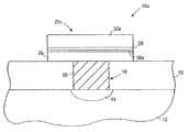
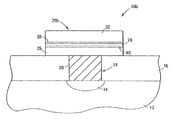
本発明はまた、メモリデバイス構造を製造する方法も提供する。本方法は、その上に第1の電極を有する基板を設けること、式M1 q(O)x(OR1)y(式I)で表される少なくとも1の前駆体化合物と式M2(NR2)w(NR3R4)z(式II)で表される少なくとも1の前駆体化合物を供給すること、前駆体化合物を気化することにより、気化した前駆体化合物を形成すること、気化した前駆体化合物を基板に供給することにより、基板の第1の電極上に金属酸化物の誘電体層を形成すること、および、誘電体層上に第2の電極を形成することを含む。式IおよびIIにおいて、M1およびM2はそれぞれ互いに独立して
金属であり、R1、R2、R3、およびR4はそれぞれ互いに独立して水素または有機基であり、xは0から4であり、yは1から8であり、wは0から4であり、zは1から8であり、qは1または2であり、x、y、z、およびwは、M1およびM2の酸化状態に依存する。
The present invention also provides a method of manufacturing a memory device structure. The method comprises providing a substrate having a first electrode thereon, at least one precursor compound represented by the formula M 1 q (O) x (OR 1 ) y (formula I) and the formula M 2 ( NR 2 ) w (NR 3 R 4 ) z (Formula II) supplying at least one precursor compound, vaporizing the precursor compound to form a vaporized precursor compound, vaporization Providing a precursor compound to the substrate to form a metal oxide dielectric layer on the first electrode of the substrate and forming a second electrode on the dielectric layer. In Formulas I and II, M 1 and M 2 are each independently a metal, R 1 , R 2 , R 3 , and R 4 are each independently hydrogen or an organic group, and x is from 0 to 4, y is 1 to 8, w is 0 to 4, z is 1 to 8, q is 1 or 2, and x, y, z, and w are M 1 and M Depends on the oxidation state of 2 .
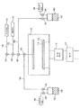
また、内部に基板を配置した蒸着チャンバと、式M1 q(O)x(OR1)y(式I)で表される1または2以上の前駆体化合物を含む1または2以上の容器と、式M2(NR2)w(NR3R4)z(式II)で表される1または2以上の前駆体化合物を含む1または2以上の容器とを備える蒸着装置も提供される。式IおよびIIにおいて、M1およびM2はそれぞれ互いに独立して金属であり、R1、R2、R3、およびR4はそれぞれ互いに独立して水素または有機基であり、xは0から4であり、yは1から8であり、wは0から4であり、zは1から8であり、qは1または2であり、x、y、z、およびwは、M1およびM2の酸化状態に依存する。 A deposition chamber having a substrate disposed therein; and one or more containers containing one or more precursor compounds represented by the formula M 1 q (O) x (OR 1 ) y (formula I); There is also provided a vapor deposition apparatus comprising one or more containers containing one or more precursor compounds represented by the formula M 2 (NR 2 ) w (NR 3 R 4 ) z (formula II). In Formulas I and II, M 1 and M 2 are each independently a metal, R 1 , R 2 , R 3 , and R 4 are each independently hydrogen or an organic group, and x is from 0 to 4, y is 1 to 8, w is 0 to 4, z is 1 to 8, q is 1 or 2, and x, y, z, and w are M 1 and M Depends on the oxidation state of 2 .
本発明の方法は、パルスCVDであってもよい化学蒸着(CVD)法を利用してもよく、原子層堆積(ALD)法(複数の堆積サイクルを含み、通常サイクル同士の間にパージを行う、自己制御方式の蒸着法)を利用してもよい。好ましくは、本発明の方法はALDを用いる。特定のALD法については、前駆体化合物は、それぞれの堆積サイクル中に交互に堆積チャンバ内に導入されてもよい。 The method of the present invention may utilize a chemical vapor deposition (CVD) method, which may be pulsed CVD, or an atomic layer deposition (ALD) method (including multiple deposition cycles, with a purge between normal cycles) Self-controlled vapor deposition method) may be used. Preferably, the method of the present invention uses ALD. For certain ALD methods, precursor compounds may be introduced alternately into the deposition chamber during each deposition cycle.
本発明はさらに、上記式Iで表される1または2以上の前駆体化合物と上記式IIで表される1または2以上の前駆体化合物を含む前駆体組成を提供する。 The present invention further provides a precursor composition comprising one or more precursor compounds represented by Formula I above and one or more precursor compounds represented by Formula II above.
「半導体基板」または「基板アセンブリ」とは、本明細書で使用する場合には、下地半導体層等の半導体基板、またはその上に1または2以上の層、構造または領域を形成した半導体基板のことを指す。下地半導体層は、通常ウエハー上のシリコン材料の一番下の層、または、サファイア上のシリコン層等、別の材料上に堆積させたシリコン層である。基板アセンブリという場合は、それよりも前にさまざまな工程段階を用いて、キャパシタの極板やキャパシタの障壁等の領域、接合、さまざまな構造もしくは特徴部、および開口部が形成または画定され得る。 As used herein, “semiconductor substrate” or “substrate assembly” refers to a semiconductor substrate such as a base semiconductor layer, or a semiconductor substrate having one or more layers, structures, or regions formed thereon. Refers to that. The underlying semiconductor layer is typically a silicon layer deposited on another material, such as the bottom layer of silicon material on the wafer or the silicon layer on sapphire. In the context of a substrate assembly, various process steps may be used prior to that to form or define regions, junctions, various structures or features, and openings, such as capacitor plates and capacitor barriers.
「層」とは、本明細書で使用する場合には、蒸着法を用いて本発明の前駆体化合物から基板上に形成することができる何らかの金属酸化物層のことを指す。「層」という用語は、「障壁層」、「誘電体層」、および「導電層」等、半導体産業に特有の層を含む層を意味する。(「層」という用語は、半導体産業においてしばしば用いられる「膜」という用語と同義である。)「層」という用語はまた、ガラス上のコーティング等、半導体技術以外の技術に見られる層を含む層をも意味する。 A “layer” as used herein refers to any metal oxide layer that can be formed on a substrate from the precursor compound of the present invention using a vapor deposition method. The term “layer” means a layer including layers specific to the semiconductor industry, such as “barrier layer”, “dielectric layer”, and “conductive layer”. (The term “layer” is synonymous with the term “film” often used in the semiconductor industry.) The term “layer” also includes layers found in technologies other than semiconductor technology, such as coatings on glass. Also means layer.
「前駆体化合物」とは、本明細書で使用する場合には、単独でまたは他の前駆体化合物とともに、蒸着法で基板上に金属酸化物層を形成することができる、金属含有化合物のことを指す。 “Precursor compound”, as used herein, is a metal-containing compound that can form a metal oxide layer on a substrate by vapor deposition, alone or in combination with other precursor compounds. Point to.
「堆積法」および「蒸着法」とは、本明細書で使用する場合には、基板(例えば、ドープしたポリシリコンウエハー)の1または2以上の表面上に気化した前駆体化合物(複数可)から金属酸化物層が形成される方法のことを指す。すなわち、1または2以上の金属含有前駆体化合物は気化し、堆積チャンバ内に配置した加熱した基板(例えば、半導体基板または基板アセンブリ)の1または2以上の表面に供給される。このような前駆体化合物は、基板の表面(複数可)上に不揮発性の薄く均一な金属酸化物層を形成する(例えば、反応または分解によって)。本発明の目的のために、「蒸着法」という用語は化学蒸着法(パルス化学蒸着法を含む)と原子層堆積法の両方を含むよう意図される。 “Deposition method” and “evaporation method” as used herein are precursor compound (s) vaporized on one or more surfaces of a substrate (eg, a doped polysilicon wafer). Refers to a method in which a metal oxide layer is formed. That is, one or more metal-containing precursor compounds are vaporized and supplied to one or more surfaces of a heated substrate (eg, a semiconductor substrate or substrate assembly) disposed in a deposition chamber. Such precursor compounds form a non-volatile thin and uniform metal oxide layer (eg, by reaction or decomposition) on the surface (s) of the substrate. For the purposes of the present invention, the term “vapor deposition” is intended to include both chemical vapor deposition (including pulsed chemical vapor deposition) and atomic layer deposition.
「化学蒸着」(CVD)とは、本明細書で使用する場合には、反応成分を分離する努力をすることなく、堆積チャンバ内で気化した金属前駆体(すなわち、金属含有前駆体)化合物(および用いる何らかの反応ガス)から基板上に所望の層を堆積させる蒸着法のことを指す。前駆体化合物と何らかの反応ガスとをほぼ同時に用いることを伴う「単純な」CVD法とは異なり、「パルス」CVDはこのような材料を堆積チャンバ内へと交互にパルス供給するが、原子層堆積すなわちALD(以下でより詳細に説明する)において通常なされる前駆体と反応ガス流との混合の厳密な回避は行わない。 “Chemical vapor deposition” (CVD), as used herein, refers to a metal precursor (ie, a metal-containing precursor) compound that has been vaporized in a deposition chamber without any effort to separate the reaction components. And any deposition gas used) refers to an evaporation method in which a desired layer is deposited on a substrate. Unlike “simple” CVD methods that involve the use of precursor compounds and some reactant gas at about the same time, “pulsed” CVD alternately pulses such materials into the deposition chamber, while atomic layer deposition That is, no strict avoidance of the mixing of the precursor and the reactant gas stream, which is usually done in ALD (described in more detail below).
「原子層堆積」(ALD)とは、本明細書で使用する場合には、堆積チャンバ内で多数の連続した堆積サイクルが行われる蒸着法のことを指す。通常、それぞれのサイクル中に金属前駆体が基板表面に化学吸着され、過剰な前駆体がパージされ、次の前駆体および/または反応ガスが導入されて化学吸着された層と反応し、過剰な反応ガス(用いる場合)および副生成物が除去される。単一サイクルの化学蒸着(CVD)法と比較して、継続時間がより長いマルチサイクルのALD法では、自己制御方式の層成長と、反応成分を分離することで好ましくない気相反応をできるだけ少なくすることとによって、層厚の制御を改善することができる。「原子層堆積」という用語はまた、本明細書で使用する場合には、前駆体化合物(複数可)、反応ガス(複数可)、およびパージ(すなわち、不活性のキャリア)ガスを交互にパルス供給する状態で行う場合の、関連用語である「原子層エピタキシー」(ALE)、分子線エピタキシー(MBE)、ガスソースMBE、有機金属MBE、およびケミカルビームエピタキシーを含むよう意図される。 “Atomic layer deposition” (ALD), as used herein, refers to an evaporation method in which a number of successive deposition cycles are performed in a deposition chamber. Typically, during each cycle, the metal precursor is chemisorbed onto the substrate surface, excess precursor is purged, the next precursor and / or reaction gas is introduced to react with the chemisorbed layer, and excess The reaction gas (if used) and by-products are removed. Compared to single cycle chemical vapor deposition (CVD), multi-cycle ALD with longer duration reduces self-controlled layer growth and separation of reaction components to minimize undesirable gas phase reactions. By doing so, the control of the layer thickness can be improved. The term “atomic layer deposition” as used herein also alternately pulses precursor compound (s), reaction gas (es), and purge (ie, inert carrier) gas. It is intended to include the related terms “atomic layer epitaxy” (ALE), molecular beam epitaxy (MBE), gas source MBE, organometallic MBE, and chemical beam epitaxy when performed in the as-provided state.
「化学吸着」とは、本明細書で使用する場合には、気化した反応性前駆体化合物の基板表面上への化学的な吸着のことを指す。吸着された化学種は、通常の化学結合に匹敵する強さである大きな吸着エネルギー(例えば、>30kcal/mol)を特徴とする比較的強い結合力の結果として、不可逆的に基板表面に結合する。化学吸着された化学種は、通常基板表面上に単分子層を形成する。("The Condensed Chemical Dictionary", 10th edition, revised by G. G. Hawley, published by Van Nostrand Reinhold Co., New York, 225 (1981) を参照されたい。)ALDの技法は、化学吸着によって反応性前駆体分子の飽和単分子層を形成するという原理に基づく。ALDでは、1または2以上の適切な前駆体化合物または反応ガスが交互に堆積チャンバ内に導入され(例えばパルス供給され)、基板表面上に化学吸着される。反応性化合物(例えば、1または2以上の前駆体化合物および1または2以上の反応ガス)の連続導入はそれぞれ、通常不活性のキャリアガスのパージによって互いから分離されている。それぞれの前駆体化合物の共反応によって、前に堆積させた層に新しい原子層が加わり、累積した固体層を形成する。このサイクルは通常数百回繰り返され、所望の層厚を徐々に形成する。ALDは、化学吸着される1の前駆体化合物と、その化学吸着された化学種と反応する1の反応ガスとを交互に利用してもよい、ということが理解されるべきである。 “Chemical adsorption”, as used herein, refers to chemical adsorption of a vaporized reactive precursor compound onto a substrate surface. The adsorbed species binds irreversibly to the substrate surface as a result of a relatively strong binding force characterized by a large adsorption energy (eg> 30 kcal / mol), a strength comparable to normal chemical bonds. . The chemisorbed chemical species usually form a monolayer on the substrate surface. (See "The Condensed Chemical Dictionary", 10th edition, revised by GG Hawley, published by Van Nostrand Reinhold Co., New York, 225 (1981).) The ALD technique uses reactive precursor molecules by chemisorption. Based on the principle of forming a saturated monomolecular layer. In ALD, one or more suitable precursor compounds or reactive gases are alternately introduced into the deposition chamber (eg, pulsed) and chemisorbed onto the substrate surface. Each successive introduction of reactive compounds (eg, one or more precursor compounds and one or more reactive gases) is separated from each other by a purge of normally inert carrier gases. The co-reaction of each precursor compound adds a new atomic layer to the previously deposited layer to form a cumulative solid layer. This cycle is usually repeated hundreds of times to gradually form the desired layer thickness. It should be understood that ALD may alternately utilize one precursor compound that is chemisorbed and one reaction gas that reacts with the chemisorbed species.
[発明の好ましい実施形態の詳細な説明]
本発明は、式M1 q(O)x(OR1)y(式I)で表される1または2以上の前駆体化合物を式M2(NR2)w(NR3R4)z(式II)で表される1または2以上の金属前駆体化合物とともに用いて、基板(好ましくは半導体基板または基板アセンブリ)上に金属酸化物層(好ましくは混合金属酸化物層)を形成する方法を提供する。式IおよびIIにおいて、M1およびM2はそれぞれ互いに独立して任意の金属(主族、遷移金属、ランタノイド)であり、それぞれのRは互いに独立して水素または有機基であり、xは0から4(好ましくは0から2)であり、yは1から8(好ましくは2から6)であり、wは0から4(好ましくは0から2)であり、zは1から8(好ましくは2から6)であり、qは1または2(好ましくは1)であり、x、y、およびzは、M1およびM2の酸化状態に依存する
。
Detailed Description of the Preferred Embodiments of the Invention
In the present invention, one or more precursor compounds represented by the formula M 1 q (O) x (OR 1 ) y (formula I) are represented by the formula M 2 (NR 2 ) w (NR 3 R 4 ) z ( A method for forming a metal oxide layer (preferably a mixed metal oxide layer) on a substrate (preferably a semiconductor substrate or substrate assembly) using one or more metal precursor compounds of formula II) provide. In formulas I and II, M 1 and M 2 are each independently any metal (main group, transition metal, lanthanoid), each R is independently hydrogen or an organic group, and x is 0 To 4 (preferably 0 to 2), y is 1 to 8 (preferably 2 to 6), w is 0 to 4 (preferably 0 to 2), and z is 1 to 8 (preferably 2 to 6), q is 1 or 2 (preferably 1), and x, y, and z depend on the oxidation states of M 1 and M 2 .
金属酸化物層は、1または2以上の異なる金属を含んでもよく、通常式MnOm(式III)で表される。ただしMは上で規定したM1およびM2のうちの1または2以上でありうる(すなわち、酸化物は単一の金属酸化物または混合金属酸化物でありうる)。好ましくは、金属酸化物層は混合金属酸化物である(すなわち、2以上の異なる金属を含む)。より好ましくは、金属酸化物層は2の異なる金属を含む。 The metal oxide layer may contain one or more different metals and is usually represented by the formula M n O m (formula III). Where M can be one or more of M 1 and M 2 defined above (ie, the oxide can be a single metal oxide or a mixed metal oxide). Preferably, the metal oxide layer is a mixed metal oxide (ie, includes two or more different metals). More preferably, the metal oxide layer comprises two different metals.
いくつかの実施形態については、式Iで表される化合物の金属と式IIで表される化合物の金属とは同じである(すなわち、M1=M2)。そのような化合物をALD法において用いる場合には、サイクル当たりの成長速度は、単一の金属前駆体と酸化ガスとを要する通常のALD法の2倍近くになる可能性がある。 For some embodiments, the metal of the compound of formula I and the metal of the compound of formula II are the same (ie, M 1 = M 2 ). When such a compound is used in an ALD process, the growth rate per cycle can be nearly twice that of a normal ALD process that requires a single metal precursor and an oxidizing gas.
金属酸化物層が2以上の異なる金属を含む場合には、金属酸化物層は、合金、固溶体、またはナノラミネートの形態であり得る。好ましくは、これらは誘電特性を有する。金属酸化物層は(特に誘電体層である場合には)、好ましくはZrO2、HfO2、Ta2O3、Al2O3、TiO2、およびランタノイド酸化物のうちの1または2以上を含む。 When the metal oxide layer includes two or more different metals, the metal oxide layer can be in the form of an alloy, a solid solution, or a nanolaminate. Preferably they have dielectric properties. The metal oxide layer (especially when it is a dielectric layer) preferably comprises one or more of ZrO 2 , HfO 2 , Ta 2 O 3 , Al 2 O 3 , TiO 2 , and lanthanoid oxides. Including.
金属酸化物層がその上に形成される基板は、好ましくは半導体基板または基板アセンブリである。例えば、導電性を有するようドープしたポリシリコン(本発明においては単に「シリコン」と呼ぶ)等、あらゆる好適な半導体材料が意図される。基板アセンブリはまた、プラチナ、イリジウム、ロジウム、ルテニウム、酸化ルテニウム、窒化チタン、窒化タンタル、タンタルシリコンナイトライド、二酸化ケイ素、アルミニウム、ガリウムヒ素、ガラス等、および例えばダイナミックランダムアクセスメモリ(DRAM)デバイスおよびスタティックランダムアクセスメモリ(SRAM)デバイス等の半導体構成において用いられるその他の現存するまたは今後開発される材料を含む層も含んでもよい。 The substrate on which the metal oxide layer is formed is preferably a semiconductor substrate or substrate assembly. Any suitable semiconductor material is contemplated, such as, for example, polysilicon doped to have electrical conductivity (referred to herein as simply “silicon”). Substrate assemblies also include platinum, iridium, rhodium, ruthenium, ruthenium oxide, titanium nitride, tantalum nitride, tantalum silicon nitride, silicon dioxide, aluminum, gallium arsenide, glass, and the like, and dynamic random access memory (DRAM) devices and static It may also include layers that include other existing or future developed materials used in semiconductor configurations such as random access memory (SRAM) devices.
本発明の方法において、半導体基板または基板アセンブリ以外の基板を用いてもよい。このようなものには、例えば繊維、ワイヤー等が含まれる。基板が半導体基板または基板アセンブリである場合には、層は基板の一番下の半導体表面上に直接形成してもよく、あるいは、例えばパターニングしたウエハーにおけるようなさまざまな層(すなわち、表面)のうちのいずれの上に形成してもよい。 In the method of the present invention, a substrate other than a semiconductor substrate or a substrate assembly may be used. Such things include, for example, fibers, wires and the like. If the substrate is a semiconductor substrate or substrate assembly, the layers may be formed directly on the bottom semiconductor surface of the substrate, or various layers (ie, surfaces) such as in a patterned wafer. You may form on any of them.
本明細書において説明する前駆体化合物は、多種多様な金属を含んでもよい。本明細書で使用する場合には、「金属」は周期表のすべての金属(主族金属、遷移金属、ランタノイド、アクチノイドを含む)ならびにメタロイドすなわち半金属を含む。本発明のいくつかの方法については、好ましくは、それぞれの金属Mは、周期表の3−7、13、14族、ランタノイドとも呼ばれるIIIB族(Sc、Y)、IVB族(Ti、Zr、Hf)、VB族(V、Nb、Ta)、VIB族(Cr、Mo、W)、VIIB族(Mn、Tc、Re)、IIIA族(Al、Ga、In、Tl)、IVA族(Si、Ge、Sn、Pb)、およびランタノイド(La、Ce、Pr、等)の金属の群から選択される。より好ましくは、Mは、Y、La、Pr、Nd、Gd、Ti、Zr、Hf、Nb、Ta、Si、およびAlの群から選択される。 The precursor compounds described herein may include a wide variety of metals. As used herein, “metal” includes all metals of the periodic table (including main group metals, transition metals, lanthanoids, actinides) as well as metalloids or metalloids. For some methods of the present invention, preferably each metal M is a group 3-7, 13, 14 of the periodic table, group IIIB (Sc, Y), also referred to as a lanthanoid, group IVB (Ti, Zr, Hf). ), VB group (V, Nb, Ta), VIB group (Cr, Mo, W), VIIB group (Mn, Tc, Re), IIIA group (Al, Ga, In, Tl), IVA group (Si, Ge) , Sn, Pb), and lanthanoid (La, Ce, Pr, etc.) metals. More preferably, M is selected from the group of Y, La, Pr, Nd, Gd, Ti, Zr, Hf, Nb, Ta, Si, and Al.
本発明において有用な前駆体化合物は、式M1(O)x(OR1)y(式I)およびM2(NR2)w(NR3R4)z(式II)で表される。ただしそれぞれのRは互いに独立して水素または有機基である。本明細書で使用する場合には、「有機基」という用語は、本発明の目的のために、脂肪基、環式基、または脂肪基と環式基との組合せ(例えば、アルカリル基およびアラルキル基)として分類される炭化水素基を意味するよう用いられる。本発明の状況において、本発明の前駆体化合物に好適な有機基は、蒸着法を用いる金属酸化物
層の形成を妨げないものである。本発明の状況において、「脂肪基」という用語は、飽和または不飽和の直鎖状または分岐状の炭化水素基を意味する。この用語は、例えばアルキル基、アルケニル基、およびアルキニル基を包含するよう用いられる。「アルキル基」という用語は、例えばメチル、エチル、n−プロピル、イソプロピル、t−ブチル、アミル、ヘプチル、等を含む、飽和の直鎖状または分岐状の一価の炭化水素基を意味する。「アルケニル基」という用語は、ビニル基等の1または2以上のオレフィン系の不飽和基(すなわち、炭素−炭素二重結合)を有する不飽和の直鎖状または分岐状の一価の炭化水素基を意味する。「アルキニル基」という用語は、1または2以上の炭素−炭素三重結合を有する不飽和の直鎖状または分岐状の一価の炭化水素基を意味する。「環式基」という用語は、脂環式基、芳香族、またはヘテロ環式基として分類される閉環状の炭化水素基を意味する。「脂環式基」という用語は、脂肪基と類似した特性を有する環式炭化水素基を意味する。「芳香族」または「アリール基」という用語は、単環式または多環式の芳香族炭化水素基を意味する。「ヘテロ環式基」という用語は、環の原子のうちの1または2以上が炭素以外の元素(例えば、窒素、酸素、硫黄、等)である、閉環状の炭化水素を意味する。
Precursor compounds useful in the present invention are represented by the formulas M 1 (O) x (OR 1 ) y (formula I) and M 2 (NR 2 ) w (NR 3 R 4 ) z (formula II). However, each R is independently hydrogen or an organic group. As used herein, the term “organic group” means, for the purposes of the present invention, an aliphatic group, a cyclic group, or a combination of an aliphatic group and a cyclic group (eg, an alkaryl group and an aralkyl group). Is used to mean a hydrocarbon group classified as a group. In the context of the present invention, suitable organic groups for the precursor compounds of the present invention are those that do not interfere with the formation of the metal oxide layer using a vapor deposition method. In the context of the present invention, the term “fatty group” means a saturated or unsaturated linear or branched hydrocarbon group. This term is used to encompass alkyl, alkenyl, and alkynyl groups, for example. The term “alkyl group” means a saturated linear or branched monovalent hydrocarbon group including, for example, methyl, ethyl, n-propyl, isopropyl, t-butyl, amyl, heptyl, and the like. The term “alkenyl group” refers to an unsaturated linear or branched monovalent hydrocarbon having one or more olefinic unsaturated groups (ie, carbon-carbon double bonds) such as vinyl groups. Means group. The term “alkynyl group” means an unsaturated linear or branched monovalent hydrocarbon group having one or more carbon-carbon triple bonds. The term “cyclic group” means a closed ring hydrocarbon group that is classified as an alicyclic group, aromatic, or heterocyclic group. The term “alicyclic group” means a cyclic hydrocarbon group having properties similar to those of an aliphatic group. The term “aromatic” or “aryl group” means a monocyclic or polycyclic aromatic hydrocarbon group. The term “heterocyclic group” means a closed ring hydrocarbon in which one or more of the ring atoms is an element other than carbon (eg, nitrogen, oxygen, sulfur, etc.).
本出願全体を通して用いるいくつかの専門用語の説明および再引用を簡素化する手段として、「基(group)」および「部分(moiety)」という用語を用いて、置換を許容するすなわち置換することができる化学種と、そのように置換を許容しないすなわちそのように置換することができない化学種とを区別する。したがって、「基」という用語を用いて化学的な置換基を説明する場合には、説明する化学材料は、置換されていない基(unsubstituted group)と、その基が、例えば過酸化物でないO、N、Si、F、またはSの原子を、カルボニル基またはその他の従来の置換基と同様に鎖に有するものとを含む。「部分」という用語を用いて化学化合物または置換基を説明する場合には、無置換の化学材料のみを含むことが意図される。例えば「アルキル基」という表現は、メチル、エチル、プロピル、t−ブチル、等の純粋な開鎖状の飽和炭化水素アルキル置換基だけでなく、ヒドロキシ、アルコキシ、アルキルスルホニル、ハロゲン原子、シアノ、ニトロ、アミノ、カルボキシ、等の当該技術分野において既知のさらなる置換基を有するアルキル置換基もまた含むよう意図される。したがって「アルキル基」は、エーテル基、ハロアルキル、ニトロアルキル、カルボキシアルキル、ヒドロキシアルキル、スルホアルキル、等を含む。他方「アルキル部分」という表現は、メチル、エチル、プロピル、t−ブチル、等、純粋な開鎖状の飽和炭化水素アルキル置換基のみを含むものに限定される。 As a means of simplifying the explanation and recitation of some terminology used throughout this application, the terms “group” and “moiety” are used to permit or substitute. A distinction is made between chemical species that are capable and those chemical species that do not allow such substitution, ie cannot be so substituted. Thus, when the term “group” is used to describe a chemical substituent, the described chemical material includes an unsubstituted group and, for example, a non-peroxide O, Including those having N, Si, F, or S atoms in the chain, as well as carbonyl groups or other conventional substituents. Where the term “moiety” is used to describe a chemical compound or substituent, it is intended to include only unsubstituted chemical materials. For example, the expression “alkyl group” includes not only pure open-chain saturated hydrocarbon alkyl substituents such as methyl, ethyl, propyl, t-butyl, but also hydroxy, alkoxy, alkylsulfonyl, halogen atoms, cyano, nitro, It is also intended to include alkyl substituents having additional substituents known in the art such as amino, carboxy, and the like. Thus “alkyl groups” include ether groups, haloalkyl, nitroalkyl, carboxyalkyl, hydroxyalkyl, sulfoalkyl, and the like. On the other hand, the expression “alkyl moiety” is limited to those containing only pure open-chain saturated hydrocarbon alkyl substituents such as methyl, ethyl, propyl, t-butyl, and the like.
本発明のすべての前駆体化合物について、それぞれのRは互いに独立しておよび好ましくは水素または有機基であり、より好ましくは(C1〜C10)有機基であり、さらにより好ましくは(C1〜C8)有機基であり、さらにより好ましくは(C1〜C6)有機基であり、さらにより好ましくは「より小さい」(すなわち、C1〜C4)有機基である。さらにより好ましくは、このような有機基のそれぞれはアルキル基である。最も好ましくは、それぞれの有機基は有機部分であり、好ましくはアルキル部分である。 For all precursor compounds of the invention, each R is independently of one another and preferably hydrogen or an organic group, more preferably a (C1-C10) organic group, even more preferably (C1-C8). An organic group, even more preferably a (C1-C6) organic group, and even more preferably a "smaller" (ie, C1-C4) organic group. Even more preferably, each such organic group is an alkyl group. Most preferably, each organic group is an organic moiety, preferably an alkyl moiety.
いくつかの実施形態において、R基の炭素原子は任意でケイ素、フッ素、酸素、および/もしくは窒素の原子またはそのような原子を含む基と交換すなわち置換される。したがって、シロキシド(siloxides)は式Iの範囲内であり、シリル化アミン(silylated amines)およびシリル化イミンアミン(silylated imine-amines)は式IIの範囲内である。 In some embodiments, the carbon atoms of the R group are optionally exchanged or substituted with silicon, fluorine, oxygen, and / or nitrogen atoms or groups containing such atoms. Thus, siloxides are within the scope of Formula I, and silylated amines and silylated imine-amines are within the scope of Formula II.
式I、M1 q(O)x(OR1)yで表される化合物について、それぞれのR1は好ましくは(C1〜C6)有機基である。好適な前駆体化合物の例は、テトラキス(t−ブトキシド)ハフニウム、テトラキス(イソプロポキシ)チタン、およびペンタ(エトキシ)タンタルを含む。そのような化合物は、シグマ・アルドリッチ等の製造業者から市販されている
か、通常の技法を用いて(例えば金属アルキルアミドの加アルコール分解によって)調製することができるかのどちらかである。
For compounds of the formula I, M 1 q (O) x (OR 1 ) y , each R 1 is preferably a (C1-C6) organic group. Examples of suitable precursor compounds include tetrakis (t-butoxide) hafnium, tetrakis (isopropoxy) titanium, and penta (ethoxy) tantalum. Such compounds are either commercially available from manufacturers such as Sigma-Aldrich or can be prepared using conventional techniques (eg, by alcoholysis of metal alkylamides).
式II、M2(NR2)w(NR3R4)zで表される化合物について、R2、R3、およびR4はそれぞれ、好ましくは(C1〜C6)有機基である。好適な前駆体化合物の例は、テトラキス(ジメチルアミノ)チタン、テトラキス(ジメチルアミノ)ハフニウム、テトラキス(エチルメチルアミノ)ハフニウム、およびAl(NMe2)2(N(Me)CH2CH2NMe2)を含む。そのような化合物は、ストレム・ケミカル社等の製造業者から市販されているか、通常の技法を用いて(例えば、金属塩化物を対応するリチウムジアルキルアミドと反応させることによって)調製することができるかのどちらかである。 For compounds of formula II, M 2 (NR 2 ) w (NR 3 R 4 ) z , R 2 , R 3 and R 4 are each preferably (C1-C6) organic groups. Examples of suitable precursor compounds are tetrakis (dimethylamino) titanium, tetrakis (dimethylamino) hafnium, tetrakis (ethylmethylamino) hafnium, and Al (NMe 2 ) 2 (N (Me) CH 2 CH 2 NMe 2 ). including. Such compounds are commercially available from manufacturers such as Strem Chemical Co. or can they be prepared using conventional techniques (eg, by reacting a metal chloride with the corresponding lithium dialkylamide) Either.
さまざまな前駆体化合物を、任意で1または2以上の有機溶剤とともに(特にCVD法の場合に)さまざまな組合せで用いて、前駆体組成を形成することができる。前駆体化合物は、室温で液体であっても固体であってもよい(好ましくは、気化温度において液体である)。通常これらは、既知の蒸着法を用いて使用するのに十分揮発性の液体である。しかしまた、固体である場合には、十分揮発性であって既知の蒸着法を用いて固体状態から気化、すなわち昇華することができればよい。揮発性の度合いが低い固体である場合には、好ましくは、有機溶剤に十分可溶であるか、または、融点が分解温度よりも下であってフラッシュ蒸発、バブリング、微小液滴形成技法等に用いることができる。本明細書において、気化した前駆体化合物は単独で用いても、任意で他の前駆体化合物の気化した分子とともに用いても、溶剤を用いる場合には任意で気化した溶剤分子とともに用いても、いずれであってもよい。本明細書で使用する場合には、「液体」とは、溶液または純粋な(neat)液体(室温で液体であるか、または、室温で固体であり温度が上昇すると溶融する)のことを指す。本明細書で使用する場合には、「溶液」は、有機溶剤によって十分な量の固体が化学蒸着法のために気相にされるならば、固体が完全に溶ける必要はなく、いくらか溶けていない固体が許容され得る。また、堆積において溶剤を希釈したものを用いる場合には、発生する溶剤蒸気の全体的なモル濃度を不活性のキャリアガスとして考えてもよい。 Various precursor compounds can be used in various combinations (especially in the case of CVD methods) optionally with one or more organic solvents to form the precursor composition. The precursor compound may be liquid or solid at room temperature (preferably liquid at the vaporization temperature). Typically these are volatile liquids that are sufficiently volatile to be used with known vapor deposition techniques. However, in the case of a solid, it is sufficient that it is sufficiently volatile and can be vaporized, that is, sublimated from a solid state using a known vapor deposition method. If it is a solid with a low degree of volatility, it is preferably sufficiently soluble in organic solvents, or has a melting point below the decomposition temperature and is suitable for flash evaporation, bubbling, microdroplet formation techniques, etc. Can be used. In the present specification, the vaporized precursor compound may be used alone, optionally together with vaporized molecules of other precursor compounds, or when used with solvent molecules optionally vaporized, Either may be sufficient. As used herein, “liquid” refers to a solution or neat liquid (which is liquid at room temperature or solid at room temperature and melts at elevated temperatures). . As used herein, a “solution” is a solid that does not have to be completely dissolved, if a sufficient amount of solid is brought into the gas phase for chemical vapor deposition by an organic solvent. No solid is acceptable. Moreover, when using what diluted the solvent in deposition, you may consider the whole molar concentration of the generated solvent vapor | steam as an inert carrier gas.
本出願に(特にCVD法に)好適な溶剤は、以下のもののうちの1または2以上であってもよい。脂肪族炭化水素または不飽和炭化水素(C3〜C20、好ましくはC5〜C10、環式、分岐状、または直鎖状)、芳香族炭化水素(C5〜C20、好ましくはC5〜C10)、ハロゲン化炭化水素、アルキルシラン等のシリル化炭化水素、アルキルケイ酸、エーテル、ポリエーテル、チオエーテル、エステル、ラクトン、アンモニア、アミド、アミン(脂肪族または芳香族、第1級、第2級、または第3級)、ポリアミン、ニトリル、シアナート、イソシアナート、チオシアナート、シリコーンオイル、アルコール、または上記のいずれかの組合せを含む化合物もしくは上記のうちの1または2以上の混合物である。化合物はまた、通常互いに両立し、さまざまな量の前駆体化合物の混合物同士が相互に作用して物理特性が著しく変わることがないようになっている。 Suitable solvents for this application (especially for CVD methods) may be one or more of the following: Aliphatic or unsaturated hydrocarbons (C3-C20, preferably C5-C10, cyclic, branched or linear), aromatic hydrocarbons (C5-C20, preferably C5-C10), halogenated Silylated hydrocarbons such as hydrocarbons, alkyl silanes, alkyl silicic acids, ethers, polyethers, thioethers, esters, lactones, ammonia, amides, amines (aliphatic or aromatic, primary, secondary, or tertiary) Grade), polyamines, nitriles, cyanates, isocyanates, thiocyanates, silicone oils, alcohols, or any combination of the above or a mixture of one or more of the above. The compounds are also usually compatible with each other so that mixtures of various amounts of precursor compounds interact with each other so that the physical properties do not change significantly.
本発明には、好ましくは、基板(通常シリコン)が酸化して酸化物(通常二酸化ケイ素)になるのをできるだけ少なくするために反応ガスは用いられない。その酸化工程はまた、金属電極または窒化物の障壁等の他の基板に好ましくない酸化をもたらしてしまう可能性がある。また、当該技術分野において既知のように、いくつかの層は酸化ガスを通して、一番上の基板層よりも下にある層に好ましくない酸化をもたらしてしまう可能性がある。 In the present invention, preferably no reaction gas is used to minimize the oxidation of the substrate (usually silicon) to the oxide (usually silicon dioxide). The oxidation process can also lead to undesirable oxidation of other substrates such as metal electrodes or nitride barriers. Also, as is known in the art, some layers may cause undesirable oxidation through layers of oxidizing gas to layers below the top substrate layer.
所望であれば、前駆体化合物は不活性のキャリアガスの存在下で気化してもよい。さらに、ALD法においては、パージ段階において不活性のキャリアガスを用いてもよい。不活性のキャリアガスは、通常、窒素、ヘリウム、アルゴン、およびそれらの組合せからな
る群から選択される。本発明の状況において、不活性のキャリアガスは金属酸化物層形成を妨げないものである。不活性のキャリアガスの存在下で行われるかどうかに関わらず、気化は好ましくは酸素非存在下で行われ、酸素による層の汚染(例えば、シリコンが酸化して二酸化ケイ素を形成)を回避する。
If desired, the precursor compound may be vaporized in the presence of an inert carrier gas. Further, in the ALD method, an inert carrier gas may be used in the purge stage. The inert carrier gas is usually selected from the group consisting of nitrogen, helium, argon, and combinations thereof. In the context of the present invention, the inert carrier gas does not interfere with the formation of the metal oxide layer. Whether or not in the presence of an inert carrier gas, vaporization is preferably performed in the absence of oxygen to avoid contamination of the layer by oxygen (eg, silicon oxidizes to form silicon dioxide). .
本発明の堆積法は蒸着法である。蒸着法は、深い接点およびその他の開口部内であっても等角性の度合いが高い(highly conformal)層を迅速に提供する工程能力のために、半導体産業において一般に好まれる。化学蒸着(CVD)と原子層堆積(ALD)とは、薄く連続的で均一な金属酸化物(好ましくは誘電体)層を半導体基板上に形成するのに用いられることが多い2つの蒸着法である。どちらの蒸着法を用いても、通常1または2以上の前駆体化合物が堆積チャンバ内で気化し任意で1または2以上の反応ガスと化合して、基板上に金属酸化物層を形成する。当業者には、プラズマ支援、光支援(photo assistance)、レーザ支援等のさまざまな関連技法ならびにその他の技法を用いることによって蒸着法を強化してもよい、ということが容易に明白となろう。 The deposition method of the present invention is a vapor deposition method. Vapor deposition is generally preferred in the semiconductor industry because of its ability to rapidly provide a highly conformal layer even within deep contacts and other openings. Chemical vapor deposition (CVD) and atomic layer deposition (ALD) are two vapor deposition methods that are often used to form a thin, continuous and uniform metal oxide (preferably dielectric) layer on a semiconductor substrate. is there. Whichever deposition method is used, typically one or more precursor compounds are vaporized in the deposition chamber and optionally combined with one or more reactive gases to form a metal oxide layer on the substrate. It will be readily apparent to those skilled in the art that deposition techniques may be enhanced by using various related techniques such as plasma assistance, photo assistance, laser assistance, and other techniques.
形成される最後の層(好ましくは誘電体層)は、好ましくは厚さが約10Åから約500Åの範囲である。より好ましくは、金属酸化物層の厚さは約30Åから約80Åの範囲である。 The last layer formed (preferably a dielectric layer) preferably has a thickness in the range of about 10 to about 500 inches. More preferably, the thickness of the metal oxide layer ranges from about 30 to about 80 inches.
大部分の蒸着法において、前駆体化合物(複数可)は通常、高温で酸化または還元を行う反応ガスと反応して金属酸化物層を形成する。しかし本発明の実施においては、式Iで表される前駆体が、形成される膜に酸素を供給するので、そのような反応ガスは不要である。しかし所望であれば、O2、O3、H2O、H2O2、およびN2O等の酸化ガスを用いてもよい。 In most vapor deposition methods, the precursor compound (s) typically react with a reaction gas that undergoes oxidation or reduction at elevated temperatures to form a metal oxide layer. However, in the practice of the present invention, such a reactive gas is not required because the precursor represented by Formula I supplies oxygen to the formed film. However, if desired, an oxidizing gas such as O 2 , O 3 , H 2 O, H 2 O 2 , and N 2 O may be used.
化学蒸着(CVD)は、半導体加工において誘電体層等の金属酸化物層の作成に幅広く用いられている。等角性の度合いが高く高品質の誘電体層を比較的速い処理時間で提供することができるからである。所望の前駆体化合物が気化され、次に、任意で反応ガスおよび/または不活性のキャリアガスがある状態で、加熱した基板を収容している堆積チャンバ内に導入される。通常のCVD法において、気化した前駆体は基板表面で反応ガス(複数可)に接触して層(例えば誘電体層)を形成する。所望の厚さの層が得られるまで単一の堆積サイクルを継続させる。 Chemical vapor deposition (CVD) is widely used in the fabrication of metal oxide layers such as dielectric layers in semiconductor processing. This is because a high quality dielectric layer having a high degree of conformality can be provided in a relatively fast processing time. The desired precursor compound is vaporized and then introduced into the deposition chamber containing the heated substrate, optionally in the presence of a reaction gas and / or an inert carrier gas. In a typical CVD method, the vaporized precursor contacts the reactive gas (es) on the substrate surface to form a layer (eg, a dielectric layer). A single deposition cycle is continued until a layer of the desired thickness is obtained.
通常のCVD法は一般に、堆積表面またはウエハーが配置されたプロセスチャンバと隔てられた、気化チャンバ内にある前駆体化合物を用いる。例えば、液体の前駆体化合物が通常バブラー内に配置されて気化温度まで加熱され、気化した液体の前駆体化合物は次に、バブラーをまたは液体の前駆体化合物を通過する不活性のキャリアガスによって搬送される。次に蒸気をガスラインを通じて堆積チャンバへと通過させ、堆積チャンバ内の基板表面(複数可)上に層を堆積させる。この工程を精密に制御する多くの技法が開発されている。例えば、前駆体化合物を収容している槽の温度および気泡になるかまたはその槽を通過する不活性のキャリアガスの流れによって、堆積チャンバに搬送される前駆体材料の量を精密に制御することができる。 Conventional CVD methods generally use a precursor compound that is in a vaporization chamber separated from the process chamber in which the deposition surface or wafer is located. For example, a liquid precursor compound is usually placed in a bubbler and heated to the vaporization temperature, and the vaporized liquid precursor compound is then transported through the bubbler or by an inert carrier gas that passes through the liquid precursor compound. Is done. Vapor is then passed through the gas line to the deposition chamber to deposit a layer on the substrate surface (s) in the deposition chamber. Many techniques have been developed to precisely control this process. For example, precise control of the amount of precursor material delivered to the deposition chamber by the temperature of the vessel containing the precursor compound and the flow of inert carrier gas that becomes or bubbles through the vessel. Can do.
本明細書において説明する前駆体化合物の好ましい実施形態は、特に化学蒸着(CVD)に好適である。基板表面における堆積温度は、好ましくは約100℃から約600℃の範囲、より好ましくは約200℃から約500℃の範囲の温度に保たれる。堆積チャンバの圧力は、好ましくは約0.1トールから約10トールの堆積圧力に維持される。不活性のキャリアガスにおける前駆体化合物の分圧は、好ましくは約0.001トールから約10トールである。 Preferred embodiments of the precursor compounds described herein are particularly suitable for chemical vapor deposition (CVD). The deposition temperature on the substrate surface is preferably maintained at a temperature in the range of about 100 ° C. to about 600 ° C., more preferably in the range of about 200 ° C. to about 500 ° C. The pressure in the deposition chamber is preferably maintained at a deposition pressure of about 0.1 Torr to about 10 Torr. The partial pressure of the precursor compound in the inert carrier gas is preferably from about 0.001 Torr to about 10 Torr.
例えば、常圧化学蒸着、減圧化学蒸着(LPCVD)、プラズマ化学蒸着(PECVD)、ホットウォール型またはコールドウォール型反応炉、または何らかのその他の化学蒸着技法を用いた、CVD法およびチャンバのいくつかの変更が可能である。さらに、ALD(以下でより詳細に説明する)と同様であるが前駆体と反応ガス流との混合の厳密な回避は行わないパルスCVDを用いてもよい。また、自己制御方式であるALDに対して、パルスCVDにおいては、堆積厚さは暴露時間に依存する(以下でより詳細に説明する)。 Some of the CVD methods and chambers using, for example, atmospheric pressure chemical vapor deposition, low pressure chemical vapor deposition (LPCVD), plasma enhanced chemical vapor deposition (PECVD), hot wall or cold wall reactors, or some other chemical vapor deposition technique It can be changed. Further, pulsed CVD may be used that is similar to ALD (described in more detail below), but does not strictly avoid mixing of the precursor and the reactant gas stream. Also, in contrast to ALD, which is a self-control method, in pulsed CVD, the deposition thickness depends on the exposure time (described in more detail below).
通常のCVD法は、ジーナス社(Genus, Inc.)(カリフォルニア州サニーベール市)から7000という商品名で入手可能な堆積チャンバ、アプライドマテリアルズ社(カリフォルニア州サンタクララ市)から5000という商品名で入手可能な堆積チャンバ、またはノヴェラス社(Novelus, Inc.)(カリフォルニア州サンノゼ市)からプリズム(Prism)という商品名で入手可能な堆積チャンバ等の化学蒸着反応炉内で行ってもよい。しかし、CVDを行うのに好適ないかなる堆積チャンバを用いてもよい。 A typical CVD process is a deposition chamber available under the trade name 7000 from Genus, Inc. (Sunnyvale, Calif.) And 5000 from Applied Materials (Santa Clara, Calif.). It may be carried out in a chemical vapor deposition reactor such as a deposition chamber available or a deposition chamber available under the trade name Prism from Novellus, Inc. (San Jose, Calif.). However, any deposition chamber suitable for performing CVD may be used.
または、そして好ましくは、本発明の方法に用いる蒸着法はマルチサイクルのALD法である。そのような方法は、堆積層(例えば、誘電体層)に対して原子レベルの厚さおよび均一性の最適な制御を行い、金属前駆体化合物を暴露する揮発温度および反応温度をより低くして劣化をできるだけ少なくする、という点で有利である(特にCVD法よりも)。通常ALD法においては、それぞれの反応物は通常約25℃から約400℃(好ましくは約150℃から約300℃)の堆積温度で好適な基板上に連続してパルス供給される。これは一般に、CVD法において現在用いられている温度よりも低い。そのような条件下では、膜成長は通常自己制御方式であり(すなわち、ALD法においては表面上の反応位置を使い切ると、通常堆積は停止する)、優れた等角性だけでなく良好な広範囲にわたる均一性、その上簡単かつ正確な厚さ制御も保証する。前駆体および/または反応ガスの連続共反応によって行われるCVD法とは異なり、前駆体化合物および/または反応ガスを交互にドーズするために、好ましくない気相反応は本質的になくなる(Vehkamaki et al,
"Growth of SrTiO3 and BaTiO3 Thin Films by Atomic Layer Deposition," Electrochemical and Solid-State Letters, 2(10):504-506 (1999)を参照されたい)。
Alternatively and preferably, the vapor deposition method used in the method of the present invention is a multi-cycle ALD method. Such methods provide optimal control of atomic thickness and uniformity for deposited layers (eg, dielectric layers), lower volatilization and reaction temperatures for exposing metal precursor compounds. This is advantageous in terms of minimizing deterioration as much as possible (especially over CVD). Typically, in ALD processes, each reactant is pulsed continuously onto a suitable substrate, usually at a deposition temperature of about 25 ° C. to about 400 ° C. (preferably about 150 ° C. to about 300 ° C.). This is generally lower than the temperature currently used in CVD methods. Under such conditions, film growth is usually self-regulating (ie, in ALD, when the reaction position on the surface is used up, deposition usually stops), not only good conformality but also a good wide range. Assures uniform uniformity, as well as simple and accurate thickness control. Unlike CVD methods, which are carried out by continuous co-reaction of precursors and / or reaction gases, undesirable gas phase reactions are essentially eliminated due to alternating doses of precursor compounds and / or reaction gases (Vehkamaki et al ,
See "Growth of SrTiO 3 and BaTiO 3 Thin Films by Atomic Layer Deposition," Electrochemical and Solid-State Letters, 2 (10): 504-506 (1999)).
通常のALD法は、基板を最初に第1の化学種(例えば、式Iで表される前駆体化合物)に暴露して、基板上への化学種の化学吸着を行うことを含む。理論的には、この化学吸着によって、暴露が行われた最初の基板全体上に、厚さが均一に1原子または分子である単分子層が形成される。言い換えれば飽和単分子層である。実際には、化学吸着は基板上のすべての部分では行われないかもしれない。しかしそのような不完全な単分子層も、本発明の状況においてはそれでもなお単分子層である。多くの用途においては、実質的に飽和した単分子層だけで好適であり得る。実質的に飽和した単分子層とは、それでもなお、そのような層に所望される品質および/または特性を呈する堆積層をもたらすものである。 A typical ALD method involves first exposing a substrate to a first chemical species (eg, a precursor compound represented by Formula I) to perform chemisorption of the chemical species onto the substrate. Theoretically, this chemisorption forms a monolayer with a uniform thickness of one atom or molecule on the entire exposed substrate. In other words, it is a saturated monolayer. In practice, chemisorption may not take place on all parts of the substrate. However, such incomplete monolayers are still monolayers in the context of the present invention. For many applications, only a substantially saturated monolayer may be suitable. A substantially saturated monolayer is still one that results in a deposited layer that exhibits the desired quality and / or properties of such a layer.
基板の上から第1の化学種がパージされ、第2の化学種(例えば、式Iで表されるものとは異なる前駆体化合物すなわち式IIで表される前駆体化合物)が供給されて、第1の化学種の第1の単分子層と反応する。次に第2の化学種がパージされ、第2の化学種の単分子層を第1の化学種に暴露して各工程が繰り返される。場合によっては、この2つの単分子層は同じ化学種であってもよい。状況により、第2の化学種は第1の化学種と反応し得るが、さらなる材料を化学吸着することはない。すなわち、第2の化学種は、化学吸着された第1の化学種の或る部分を切断して、その単分子層を、その上に別の単分子層を形成することなく改変し得る。また、第1および第2の化学種について説明したのと同様に、第3の化学種またはそれよりも多くが連続して化学吸着され(すなわち反応し)パージされてもよい。任意で、所望であれば、第2の化学種(または第3もしくはその次の)は
、少なくとも1の反応ガスを含んでもよい。
A first chemical species is purged from above the substrate and a second chemical species (eg, a precursor compound different from that represented by Formula I or a precursor compound represented by Formula II) is provided, Reacts with the first monolayer of the first chemical species. The second chemical species is then purged and the steps are repeated with the second chemical species monolayer exposed to the first chemical species. In some cases, the two monolayers may be the same chemical species. Depending on the circumstances, the second species may react with the first species, but does not chemisorb additional material. That is, the second chemical species can cut a portion of the chemisorbed first chemical species and modify its monolayer without forming another monolayer thereon. Also, as described for the first and second chemical species, the third chemical species or more may be continuously chemisorbed (ie, reacted) and purged. Optionally, if desired, the second chemical species (or third or subsequent) may include at least one reactive gas.
パージは、基板および/または単分子層をキャリアガスに接触させること、および/または圧力を堆積圧力未満まで下げて基板に接触している化学種および/または化学吸着された化学種の濃度を下げることを含むがこれに限定されないさまざまな技法を含んでもよい。キャリアガスの例は、N2、Ar、He、等を含む。パージはその代わりに、別の化学種の導入に先立って、基板および/または単分子層を、化学吸着の副生成物の脱着をし、接触している化学種の濃度を下げ得る何らかの物質に接触させることを含んでもよい。接触している化学種は、個々の堆積法の製品についての仕様書に基づいて当業者に既知の或る好適な濃度または分圧まで下げてもよい。 Purging brings the substrate and / or monolayer into contact with a carrier gas and / or lowers the pressure below the deposition pressure to reduce the concentration of species that are in contact with the substrate and / or chemisorbed species. Various techniques may be included, including but not limited to. Examples of the carrier gas include N 2 , Ar, He, and the like. Instead, purging, instead of introducing another species, the substrate and / or monolayer is desorbed by any chemisorption by-product and reduced to some material that can reduce the concentration of the contacting species. It may include contacting. The contacting chemical species may be reduced to some suitable concentration or partial pressure known to those skilled in the art based on the specifications for the individual deposition process product.
ALDは、基板上に存在する、第1の化学種の化学結合形成可能な位置の数が有限であるという点において、自己制御方式の方法として説明されることが多い。第2の化学種は、第1の化学種のみに結合する可能性があり、したがってこれもまた自己制御方式であり得る。基板上の有限数の位置のすべてがいったん第1の化学種に結合されると、第1の化学種は、既に基板に結合した他の第1の化学種には結合しないことが多い。しかしALDにおいて、そのような結合を促進しALDを非自己制御方式にするよう、工程条件を変更してもよい。したがって、ALDはまた、化学種を積み重ねて1原子または分子よりも厚い層を形成することによって、一度に1の単分子層とは別のものを形成する化学種も包含してもよい。 ALD is often described as a self-control method in that the number of positions on the substrate where a chemical bond of the first chemical species can be formed is finite. The second species may only bind to the first species, so this can also be self-regulating. Once all of the finite number of locations on the substrate are bound to the first chemical species, the first chemical species often does not bind to other first chemical species that are already bound to the substrate. However, in ALD, process conditions may be changed to promote such binding and to make ALD non-self-controlling. Thus, ALD may also include chemical species that form one monolayer at a time by stacking chemical species to form a layer thicker than one atom or molecule.
説明する方法は、第1の前駆体の化学吸着中に第2の前駆体(すなわち、第2の化学種)が「実質的にない」ことを示す。存在する第2の前駆体がわずかである可能性があるからである。当業者の知識および好みに従って、第2の前駆体が実質的にないことを達成するために選択された第2の前駆体の許容量および工程条件に関して決定することができる。 The described method indicates that the second precursor (ie, the second species) is “substantially free” during chemisorption of the first precursor. This is because there may be a small amount of the second precursor present. In accordance with the knowledge and preference of those skilled in the art, a determination can be made regarding the tolerance and process conditions of the second precursor selected to achieve substantially no second precursor.
したがって、ALD法の間、堆積チャンバ内で多数の連続した堆積サイクルが行われ、それぞれのサイクルでは非常に薄い金属酸化物層(通常1の単分子層よりも薄く、成長速度が平均してサイクル当たり約0.2から約3.0オングストロームになるようになっている)が堆積し、ついには対象基板上に所望の厚さの層が形成される。層の堆積は、半導体基板を収容している堆積チャンバ内に前駆体化合物を交互に導入し(すなわち、パルス供給によって)、前駆体化合物(複数可)を単分子層として基板表面上に化学吸着し、次に化学吸着された前駆体化合物(複数可)を他の共反応性の前駆体化合物(複数可)と反応させることによって行われる。前駆体化合物(複数可)および不活性のキャリアガス(複数可)のパルス幅は、基板表面を飽和させるのに十分である。通常パルス幅は約0.1から約5秒であり、好ましくは約0.2から約1秒である。 Thus, during ALD, a number of successive deposition cycles are performed in the deposition chamber, each cycle being a very thin metal oxide layer (usually thinner than one monolayer, with an average growth rate of cycles). From about 0.2 to about 3.0 angstroms), and finally a layer of the desired thickness is formed on the target substrate. Layer deposition involves introducing precursor compounds alternately into a deposition chamber containing a semiconductor substrate (ie, by pulsing) and chemisorbing the precursor compound (s) as a monolayer onto the substrate surface. And then reacting the chemisorbed precursor compound (s) with other co-reactive precursor compound (s). The pulse width of the precursor compound (s) and inert carrier gas (es) is sufficient to saturate the substrate surface. Usually the pulse width is about 0.1 to about 5 seconds, preferably about 0.2 to about 1 second.
主として熱によって駆動されるCVDと比較して、ALDは主として化学作用によって駆動される。したがって、ALDはCVDよりもはるかに低温で行われることが多い。ALD法の間、基板温度は、化学吸着された前駆体化合物(複数可)とその下にある基板表面との間の完全な結合を維持し前駆体化合物(複数可)の分解を防止するのに十分低い温度に維持される。この温度はまた、前駆体化合物(複数可)の凝縮を回避するのに十分高い。通常基板温度は、約25℃から約400℃(好ましくは約150℃から約300℃)の範囲内に保たれ、これは一般に、CVD法において現在用いられている温度よりも低い。したがって、この温度で第1の化学種すなわち前駆体化合物が化学吸着される。第2の化学種すなわち前駆体化合物の表面反応は、第1の前駆体の化学吸着と実質的に同じ温度で起こり得るが、より好ましくはないが実質的に異なる温度でも起こりうる。明らかに、当業者が判断していくらかの小さな温度変化は生じる可能性があるが、それでもこれは、第1の前駆体の化学吸着温度で生じるのと統計学的に同じ反応速度を供給することによっ
て、実質的に同じ温度であり得る。そうではなく、化学吸着と次の反応とは厳密に同じ温度で行われてもよい。
Compared to CVD, which is driven mainly by heat, ALD is driven mainly by chemical action. Therefore, ALD is often performed at a much lower temperature than CVD. During the ALD process, the substrate temperature maintains a perfect bond between the chemisorbed precursor compound (s) and the underlying substrate surface and prevents decomposition of the precursor compound (s). At a sufficiently low temperature. This temperature is also high enough to avoid condensation of the precursor compound (s). Usually the substrate temperature is kept in the range of about 25 ° C. to about 400 ° C. (preferably about 150 ° C. to about 300 ° C.), which is generally lower than the temperature currently used in CVD processes. Thus, at this temperature, the first chemical species or precursor compound is chemisorbed. The surface reaction of the second species or precursor compound can occur at substantially the same temperature as the chemisorption of the first precursor, but more preferably, it can also occur at a substantially different temperature. Obviously, some small temperature changes may occur, as judged by one skilled in the art, but this still provides the same rate of reaction as occurs at the chemisorption temperature of the first precursor. Can be at substantially the same temperature. Instead, the chemisorption and the next reaction may be performed at exactly the same temperature.
通常のALD法については、堆積チャンバ内の圧力は約10-4トールから約1トール、好ましくは約10-4トールから約0.1トールに保たれる。通常堆積チャンバは、それぞれのサイクルで気化した前駆体化合物(複数可)がチャンバに導入された後および/または反応した後に、不活性のキャリアガスでパージされる。不活性のキャリアガス(複数可)はまた、それぞれのサイクル中に気化した前駆体化合物(複数可)とともに導入されてもよい。 For a typical ALD process, the pressure in the deposition chamber is maintained from about 10-4 torr to about 1 torr, preferably from about 10-4 torr to about 0.1 torr. Typically, the deposition chamber is purged with an inert carrier gas after the precursor compound (s) vaporized in each cycle have been introduced into the chamber and / or reacted. Inert carrier gas (es) may also be introduced with the precursor compound (s) vaporized during each cycle.
前駆体化合物の反応性は、ALDにおいて工程パラメータに著しく影響を及ぼし得る。通常のCVD法の条件の下では、高反応性化合物は気相で反応して、微粒子を発生し、不所望の表面上に早過ぎる堆積が行われ、劣悪な膜を生成し、および/または劣悪な段差被覆性をもたらすか、もしくは他の方法で不均一な堆積をもたらす場合がある。少なくともそのような理由から、高反応性化合物はCVDには好適でないと考えられるかもしれない。しかし、CVDには好適でない化合物には、ALDの優れた前駆体であるものもある。例えば、第1の前駆体が気相で第2の前駆体と反応する場合には、そのような化合物の組合せはCVDには好適でないかもしれないが、ALDにおいては用いることができる。当業者には既知のように、CVDの状況においては、気相での高反応性前駆体を用いる場合に固着係数および表面移動度に関しても問題があるかもしれない。しかしALDの状況においては、そのような問題はほとんどまたは全くない。 The reactivity of the precursor compound can significantly affect process parameters in ALD. Under normal CVD conditions, highly reactive compounds react in the gas phase, generating particulates, premature deposition on undesired surfaces, producing poor films, and / or It may result in poor step coverage or otherwise non-uniform deposition. For at least such reasons, highly reactive compounds may be considered unsuitable for CVD. However, some compounds not suitable for CVD are excellent precursors for ALD. For example, if the first precursor reacts with the second precursor in the gas phase, such a combination of compounds may not be suitable for CVD, but can be used in ALD. As known to those skilled in the art, in the context of CVD, there may also be problems with sticking coefficient and surface mobility when using highly reactive precursors in the gas phase. However, in ALD situations there is little or no such problem.
基板上に層を形成した後に任意で、堆積チャンバにおいて窒素雰囲気中でまたは酸化雰囲気中で、アニール工程を原位置で行ってもよい。好ましくは、アニール温度は約400℃から約1000℃の範囲内である。特にALD後、アニール温度はより好ましくは約400℃から約750℃、最も好ましくは約600℃から約700℃である。アニール操作は、好ましくは約0.5分から約60分の期間、より好ましくは約1分から約10分の期間行われる。当業者であれば、そのような温度および期間はさまざまであってもよいということを理解しよう。例えば、炉アニールおよび高速熱アニールを用いてもよく、さらに、そのようなアニールは1または2以上のアニール工程で行ってもよい。 Optionally, after forming the layer on the substrate, the annealing step may be performed in situ in a deposition chamber in a nitrogen atmosphere or in an oxidizing atmosphere. Preferably, the annealing temperature is in the range of about 400 ° C to about 1000 ° C. Particularly after ALD, the annealing temperature is more preferably from about 400 ° C. to about 750 ° C., most preferably from about 600 ° C. to about 700 ° C. The annealing operation is preferably performed for a period of about 0.5 minutes to about 60 minutes, more preferably for a period of about 1 minute to about 10 minutes. One skilled in the art will appreciate that such temperatures and durations may vary. For example, furnace annealing and rapid thermal annealing may be used, and such annealing may be performed in one or more annealing steps.
上述のように、本発明の膜を形成する配位化合物(錯体、complexes)および方法を用いることは、半導体構造における広くさまざまな薄膜の用途、特に高誘電材料を用いるものに有利である。例えば、そのような用途は、平板セル、トレンチセル(例えば二重側壁トレンチキャパシタ(double sidewall trench capacitors))、スタックセル(例えば、クラウン、Vセル、デルタセル、マルチフィンガ、または円筒状の容器のスタックキャパシタ)、ならびに電界効果トランジスタデバイス等のキャパシタを含む。 As mentioned above, the use of coordination compounds and methods for forming the films of the present invention is advantageous for a wide variety of thin film applications in semiconductor structures, particularly those using high dielectric materials. For example, such applications include planar cells, trench cells (eg, double sidewall trench capacitors), stack cells (eg, crown, V cell, delta cell, multi-finger, or cylindrical container stacks) Capacitors), as well as capacitors such as field effect transistor devices.
キャパシタ構成は、本発明に従って誘電体層が形成される一具体例である。例示的キャパシタ構成を図1ないし図3を参照して説明する。図1を参照して、半導体ウエハー個片10は、本発明の方法によって形成されたキャパシタ構成25を含む。ウエハー個片10は、内部に導電性の拡散領域14を形成した基板12を含む。基板12は例えば単結晶シリコンを含んでもよい。基板12の上に、通常ボロフォスフォシリケート(ホウ素リンケイ酸、borophosphosilicate)ガラス(BPSG)である絶縁層16が、拡散領域14へのコンタクト開口18を内部に設けた状態で設けられる。導電性材料20および酸化物層18を図示のように平坦化した状態で、コンタクト開口18を導電性材料20で充填する。材料20は、例えばタングステンまたは導電性を有するようドープしたポリシリコン等、いかなる好適な導電性材料であってもよい。キャパシタ構成25が層16およびプラグ20の上に設けられ、プラグ20を介してノード14に電気接続される。
The capacitor configuration is one specific example in which a dielectric layer is formed according to the present invention. An exemplary capacitor configuration will be described with reference to FIGS. Referring to FIG. 1, a
キャパシタ構成25は、ノード20の上に設けられパターニングされている第1のキャパシタ電極26を含む。例示的材料は、導電性を有するようドープしたポリシリコン、Pt、Ir、Rh、Ru、RuO2、IrO2、RhO2を含む。第1のキャパシタ電極26の上にキャパシタ誘電体層28が設けられる。本発明の材料を用いてキャパシタ誘電体層28を形成してもよい。好ましくは、第1のキャパシタ電極26がポリシリコンを含む場合には、誘電材料の堆積前にポリシリコン表面が原位置HF浸漬によってクリーニングされる。256Mbの集積による層28の例示的厚さは、100オングストロームである。
誘電体層28の上に拡散障壁層30が設けられる。拡散障壁層30は、TiN、TaN、金属シリサイド、または金属シリサイドニトリド等の導電性材料を含み、例えば当業者に既知の条件を用いて、CVDによって設けられてもよい。障壁層30の形成後、障壁層30の上に第2のキャパシタ電極32が形成されて、キャパシタ25の構成を完成する。第2のキャパシタ電極32は、第1のキャパシタ電極26に関して上述したものと同様の構成を含んでもよく、したがって例えば導電性を有するようドープしたポリシリコンを含んでもよい。拡散障壁層30は、好ましくは、成分(例えば酸素)が誘電材料28から電極32内へと拡散しないようにする。例えば酸素は、シリコン含有電極32内へと拡散すると、SiO2を不所望に形成してしまう可能性があり、それによってキャパシタ25の静電容量が著しく減ってしまう。拡散障壁層30はまた、シリコンが金属電極32から誘電体層28へと拡散しないようにすることができる。
A
図2は、キャパシタ構成の他の実施形態を示す。適当な場所には図1と同様の数字が利用されており、後ろにつける「a」によって相違を示す。ウエハー個片10aは、障壁層30aを誘電体層28と第2のキャパシタ電極32との間ではなく第1の電極26と誘電体層28との間に設けているという点で図2の構成25とは異なる、キャパシタ構成25aを含む。障壁層30aは、図1に関して上述したものと同一の構成を含んでもよい。
FIG. 2 illustrates another embodiment of a capacitor configuration. The numbers similar to those in FIG. 1 are used at appropriate places, and the difference is indicated by “a” attached behind. The
図3は、キャパシタ構成のさらに別の他の実施形態を示す。適当な場所には図1と同様の数字が利用されており、後ろにつける「b」によってまたは異なる数字によって相違を示す。ウエハー個片10bは、第1の説明した実施形態の第1のキャパシタ極板26および第2のキャパシタ極板32をそれぞれ有するキャパシタ構成25bを含む。しかしウエハー個片10bは、障壁層30に加えて第2の障壁層40を含むという点で図2のウエハー個片10とは異なる。障壁層40は第1のキャパシタ電極26と誘電体層28との間に設けられるのに対し、障壁層30は第2のキャパシタ電極32と誘電体層28との間である。障壁層40は、障壁層30の形成について図1を参照して上述したものと同一の方法によって形成してもよい。
FIG. 3 shows yet another embodiment of a capacitor configuration. The same numbers as in FIG. 1 are used in appropriate places, and the difference is indicated by “b” attached behind or by a different number.
図1ないし図3の実施形態において、障壁層は、キャパシタ電極とは分離された別個の層として示し説明している。しかし、障壁層は導電性材料を含んでもよく、したがってそのような実施形態においてはキャパシタ電極の少なくとも一部を含むと理解することができる。個々の実施形態において、キャパシタ電極全体が導電性障壁層材料を含んでもよい。 In the embodiment of FIGS. 1-3, the barrier layer is shown and described as a separate layer separate from the capacitor electrode. However, it can be understood that the barrier layer may comprise a conductive material, and thus includes at least a portion of the capacitor electrode in such embodiments. In individual embodiments, the entire capacitor electrode may include a conductive barrier layer material.
本発明の蒸着法(化学蒸着または原子層堆積)を行うのに用いることができるシステムを図4に示す。システムは密閉した蒸着チャンバ110を含み、この中でターボポンプ112およびバッキングポンプ114を用いて真空を作り出すことができる。チャンバ110内に1または2以上の基板116(例えば半導体基板または基板アセンブリ)が配置される。基板116について一定の公称温度が確立され、この温度は、用いる工程次第でさまざまであり得る。基板116は、例えばその上に基板116が搭載される電気抵抗ヒータ118によって加熱してもよい。基板を加熱する他の既知の方法もまた利用することができる。
A system that can be used to perform the vapor deposition method (chemical vapor deposition or atomic layer deposition) of the present invention is shown in FIG. The system includes a sealed
この工程において、前駆体化合物160(例えば耐火性の金属前駆体化合物およびエーテル)が容器162内に保管されている。前駆体化合物は気化し、例えば不活性のキャリアガス168を用いて、ライン164、166に沿って別個に堆積チャンバ110へと供給される。必要に応じて、ライン172に沿って反応ガス170を供給してもよい。また、必要に応じて、不活性のキャリアガス168と同じであることが多いパージガス174をライン176に沿って供給してもよい。図示のように、一連の弁180〜185が必要に応じて開閉される。
In this step, a precursor compound 160 (for example, a refractory metal precursor compound and ether) is stored in the
さまざまな具体的かつ好ましい実施形態および技法をさらに説明するために、以下に実施例を示す。しかし、本発明の範囲内で多くの変形および変更を行ってもよく、したがって本発明の範囲は実施例によって限定されることを意図するものではない、ということが理解されるべきである。特に明記のない限り、実施例において示す割合はすべて重量パーセントである。 The following examples are provided to further illustrate various specific and preferred embodiments and techniques. However, it should be understood that many variations and modifications may be made within the scope of the present invention, and thus the scope of the present invention is not intended to be limited by the examples. Unless otherwise specified, all percentages shown in the examples are percent by weight.
[実施例1.(Hf,Ti)O2の原子層堆積]
連続的な方法でパルス状に弁を開くコンピュータ制御下の空圧弁を有する図4に示す構成のチャンバを、作動した。チャンバには、Ti(NMe2)4とHf(OC(CH3)3)4(マサチューセッツ州ニューベリーポート市のストレム・ケミカル社)を収容している2つの槽がつながっていた。基板は一番上の層としてドープしたポリシリコンを有するシリコンウエハーであり、堆積に備えて150℃に維持された。
[Example 1. (Hf, Ti) Atomic layer deposition of O 2 ]
A chamber configured as shown in FIG. 4 with a pneumatic valve under computer control that opens the valve in a continuous manner was operated. Connected to the chamber were two tanks containing Ti (NMe 2 ) 4 and Hf (OC (CH 3 ) 3 ) 4 (Strem Chemical Co., Newburyport, Mass.). The substrate was a silicon wafer with doped polysilicon as the top layer and maintained at 150 ° C. in preparation for deposition.
それぞれのサイクルは、5秒間のHf(OC(CH3)3)4のパルス供給および5秒間のTi(NMe2)4のパルス供給を含み、それぞれは10秒間のアルゴンでのパージと20秒間の動的真空下でのポンプダウンとによって分離された。前駆体は、5sccmに設定したマスフローコントローラを用いて、ヘリウムキャリアガスとともに導入された。400サイクル後、厚さ180Åの(Hf,Ti)O2膜が得られた。膜はX線光電子分光法(XPS)による分析に基づいてHF/Tiがほぼ50/50であり、検出可能な窒素または炭素は有しなかった。 Each cycle included a 5 second pulse of Hf (OC (CH 3 ) 3 ) 4 and a 5 second pulse of Ti (NMe 2 ) 4 , each of which was purged with 10 seconds of argon and 20 seconds. Separated by pumping down under dynamic vacuum. The precursor was introduced with a helium carrier gas using a mass flow controller set at 5 sccm. After 400 cycles, a (Hf, Ti) O 2 film having a thickness of 180 mm was obtained. The film was approximately 50/50 HF / Ti based on analysis by X-ray photoelectron spectroscopy (XPS) and had no detectable nitrogen or carbon.
本明細書において引用される特許、特許文献、および刊行物の完全な開示は、参照により、あたかもそれぞれが個々に援用されるかのようにその全体が援用される。当業者には、本発明の範囲および精神から逸脱することのない、本発明へのさまざまな修正および変更が明らかであろう。本発明は本明細書において示す説明的な実施形態および実施例によって過度に限定されるよう意図するものではなく、そのような実施例および実施形態は例としてのみ提示されるものであって、本発明の範囲は本明細書において以下に示す特許請求の範囲によってのみ限定されるよう意図するものである、ということが理解されるべきである。 The complete disclosures of the patents, patent documents, and publications cited herein are incorporated by reference in their entirety as if each were individually incorporated. Various modifications and alterations to this invention will be apparent to those skilled in the art without departing from the scope and spirit of this invention. The present invention is not intended to be unduly limited by the illustrative embodiments and examples set forth herein, which examples and embodiments are presented by way of example only, and It is to be understood that the scope of the invention is intended to be limited only by the claims set forth herein below.
Claims (20)
式M1 q(O)x(OR1)y(式I)で表される少なくとも1の前駆体化合物と式M2(NR2)w(NR3R4)z(式II)で表される少なくとも1の前駆体化合物を供給すること、
および蒸着法を用いて、前記両前駆体化合物を前記基板上に接触させることにより、金属酸化物層を形成することを含む、基板上に金属酸化物層を形成する方法であって、
前記蒸着法は、複数の堆積サイクルを含む原子層堆積法である方法;
前記式において、
M1およびM2は同じ金属であり、
それぞれのR1は互いに独立して有機基であり、
R2、R3、およびR4はそれぞれ互いに独立して水素または有機基であり、
xは0から4であり、
yは1から8であり、
wは0から4であり、
zは1から8であり、
qは1または2であり、
x、y、z、およびwは、M1およびM2の酸化状態に依存する。 Preparing the substrate,
At least one precursor compound represented by the formula M 1 q (O) x (OR 1 ) y (formula I) and the formula M 2 (NR 2 ) w (NR 3 R 4 ) z (formula II) Providing at least one precursor compound
And forming a metal oxide layer on the substrate , comprising contacting the two precursor compounds with the substrate using a vapor deposition method, and forming a metal oxide layer ,
The vapor deposition method is an atomic layer deposition method including a plurality of deposition cycles;
In the above formula,
M 1 and M 2 are the same metal,
Each R 1 is independently an organic group,
R 2 , R 3 , and R 4 are each independently hydrogen or an organic group;
x is from 0 to 4,
y is 1 to 8,
w is from 0 to 4,
z is 1 to 8,
q is 1 or 2,
x, y, z, and w depend on the oxidation state of M 1 and M 2 .
前記方法は、前記両前駆体化合物を気化することにより、気化した両前駆体化合物を形成すること、 The method includes forming both vaporized precursor compounds by vaporizing the two precursor compounds;
および前記気化した両前駆体化合物を、前記半導体基板または基板アセンブリに供給することにより、該半導体基板または基板アセンブリの1または2以上の表面上に金属酸化物の誘電体層を形成することを含む、請求項14又は15に記載の方法。 And supplying both vaporized precursor compounds to the semiconductor substrate or substrate assembly to form a metal oxide dielectric layer on one or more surfaces of the semiconductor substrate or substrate assembly. The method according to claim 14 or 15.
前記方法は、前記両前駆体化合物を気化することにより、気化した両前駆体化合物を形成すること、The method includes forming both vaporized precursor compounds by vaporizing the two precursor compounds;
該気化した両前駆体化合物を、前記基板に供給することにより、該基板の前記第1の電極上に金属酸化物の誘電体層を形成すること、 Supplying the vaporized both precursor compounds to the substrate to form a metal oxide dielectric layer on the first electrode of the substrate;
および該誘電体層上に第2の電極を形成することを含む方法。 And forming a second electrode on the dielectric layer.
式M1 q(O)x(OR1)y(式I)で表される1または2以上の前駆体化合物を含む1または2以上の容器と、
式M2(NR2)w(NR3R4)z(式II)で表される1または2以上の前駆体化合物を含む1または2以上の容器を備える蒸着装置であって、
前記前駆体化合物の気化および供給は、複数の堆積サイクルを含む原子層堆積法を用いて達成される装置;
前記式において、
M1およびM2は同じ金属であり、
それぞれのR1は互いに独立して有機基であり、
R2、R3、およびR4はそれぞれ互いに独立して水素または有機基であり、
xは0から4であり、
yは1から8であり、
wは0から4であり、
zは1から8であり、
qは1または2であり、
x、y、z、およびwは、M1およびM2の酸化状態に依存する。A deposition chamber having a substrate disposed therein;
One or more containers comprising one or more precursor compounds of the formula M 1 q (O) x (OR 1 ) y (formula I);
A vapor deposition apparatus comprising one or more containers containing one or more precursor compounds represented by the formula M 2 (NR 2 ) w (NR 3 R 4 ) z (formula II),
An apparatus wherein vaporization and delivery of the precursor compound is accomplished using an atomic layer deposition method comprising a plurality of deposition cycles;
In the above formula,
M 1 and M 2 are the same metal,
Each R 1 is independently an organic group,
R 2 , R 3 , and R 4 are each independently hydrogen or an organic group;
x is from 0 to 4,
y is 1 to 8,
w is from 0 to 4,
z is 1 to 8,
q is 1 or 2,
x, y, z, and w depend on the oxidation state of M 1 and M 2 .
Applications Claiming Priority (2)
| Application Number | Priority Date | Filing Date | Title |
|---|---|---|---|
| US10/229,627 US6958300B2 (en) | 2002-08-28 | 2002-08-28 | Systems and methods for forming metal oxides using metal organo-amines and metal organo-oxides |
| PCT/US2003/026789 WO2004020689A2 (en) | 2002-08-28 | 2003-08-27 | Systems and methods for forming metal oxides using metal organo-amines and metal organo-oxides |
Publications (3)
| Publication Number | Publication Date |
|---|---|
| JP2005537638A JP2005537638A (en) | 2005-12-08 |
| JP2005537638A5 JP2005537638A5 (en) | 2006-10-05 |
| JP4355656B2 true JP4355656B2 (en) | 2009-11-04 |
Family
ID=31976278
Family Applications (1)
| Application Number | Title | Priority Date | Filing Date |
|---|---|---|---|
| JP2004531530A Expired - Lifetime JP4355656B2 (en) | 2002-08-28 | 2003-08-27 | System and method for forming metal oxides using metal organic amines and metal organic oxides |
Country Status (8)
| Country | Link |
|---|---|
| US (2) | US6958300B2 (en) |
| EP (1) | EP1532291B1 (en) |
| JP (1) | JP4355656B2 (en) |
| KR (1) | KR20050043926A (en) |
| CN (1) | CN1688743A (en) |
| AU (1) | AU2003262900A1 (en) |
| TW (1) | TWI270579B (en) |
| WO (1) | WO2004020689A2 (en) |
Families Citing this family (92)
| Publication number | Priority date | Publication date | Assignee | Title |
|---|---|---|---|---|
| US6974766B1 (en) * | 1998-10-01 | 2005-12-13 | Applied Materials, Inc. | In situ deposition of a low κ dielectric layer, barrier layer, etch stop, and anti-reflective coating for damascene application |
| US6620723B1 (en) * | 2000-06-27 | 2003-09-16 | Applied Materials, Inc. | Formation of boride barrier layers using chemisorption techniques |
| US6551929B1 (en) | 2000-06-28 | 2003-04-22 | Applied Materials, Inc. | Bifurcated deposition process for depositing refractory metal layers employing atomic layer deposition and chemical vapor deposition techniques |
| US7101795B1 (en) | 2000-06-28 | 2006-09-05 | Applied Materials, Inc. | Method and apparatus for depositing refractory metal layers employing sequential deposition techniques to form a nucleation layer |
| US7405158B2 (en) | 2000-06-28 | 2008-07-29 | Applied Materials, Inc. | Methods for depositing tungsten layers employing atomic layer deposition techniques |
| US6596643B2 (en) * | 2001-05-07 | 2003-07-22 | Applied Materials, Inc. | CVD TiSiN barrier for copper integration |
| US20090004850A1 (en) | 2001-07-25 | 2009-01-01 | Seshadri Ganguli | Process for forming cobalt and cobalt silicide materials in tungsten contact applications |
| US9051641B2 (en) | 2001-07-25 | 2015-06-09 | Applied Materials, Inc. | Cobalt deposition on barrier surfaces |
| US8110489B2 (en) | 2001-07-25 | 2012-02-07 | Applied Materials, Inc. | Process for forming cobalt-containing materials |
| US20030059538A1 (en) * | 2001-09-26 | 2003-03-27 | Applied Materials, Inc. | Integration of barrier layer and seed layer |
| US7049226B2 (en) * | 2001-09-26 | 2006-05-23 | Applied Materials, Inc. | Integration of ALD tantalum nitride for copper metallization |
| US6916398B2 (en) | 2001-10-26 | 2005-07-12 | Applied Materials, Inc. | Gas delivery apparatus and method for atomic layer deposition |
| US7081271B2 (en) | 2001-12-07 | 2006-07-25 | Applied Materials, Inc. | Cyclical deposition of refractory metal silicon nitride |
| WO2003065424A2 (en) | 2002-01-25 | 2003-08-07 | Applied Materials, Inc. | Apparatus for cyclical deposition of thin films |
| US6911391B2 (en) | 2002-01-26 | 2005-06-28 | Applied Materials, Inc. | Integration of titanium and titanium nitride layers |
| US6833161B2 (en) | 2002-02-26 | 2004-12-21 | Applied Materials, Inc. | Cyclical deposition of tungsten nitride for metal oxide gate electrode |
| US6846516B2 (en) * | 2002-04-08 | 2005-01-25 | Applied Materials, Inc. | Multiple precursor cyclical deposition system |
| US7279432B2 (en) | 2002-04-16 | 2007-10-09 | Applied Materials, Inc. | System and method for forming an integrated barrier layer |
| US20030235961A1 (en) * | 2002-04-17 | 2003-12-25 | Applied Materials, Inc. | Cyclical sequential deposition of multicomponent films |
| AU2003224977A1 (en) * | 2002-04-19 | 2003-11-03 | Mattson Technology, Inc. | System for depositing a film onto a substrate using a low vapor pressure gas precursor |
| US7160577B2 (en) | 2002-05-02 | 2007-01-09 | Micron Technology, Inc. | Methods for atomic-layer deposition of aluminum oxides in integrated circuits |
| US6858547B2 (en) * | 2002-06-14 | 2005-02-22 | Applied Materials, Inc. | System and method for forming a gate dielectric |
| US20030232501A1 (en) * | 2002-06-14 | 2003-12-18 | Kher Shreyas S. | Surface pre-treatment for enhancement of nucleation of high dielectric constant materials |
| US7067439B2 (en) * | 2002-06-14 | 2006-06-27 | Applied Materials, Inc. | ALD metal oxide deposition process using direct oxidation |
| US7112485B2 (en) | 2002-08-28 | 2006-09-26 | Micron Technology, Inc. | Systems and methods for forming zirconium and/or hafnium-containing layers |
| US6984592B2 (en) * | 2002-08-28 | 2006-01-10 | Micron Technology, Inc. | Systems and methods for forming metal-doped alumina |
| US7253122B2 (en) * | 2002-08-28 | 2007-08-07 | Micron Technology, Inc. | Systems and methods for forming metal oxides using metal diketonates and/or ketoimines |
| US7087481B2 (en) * | 2002-08-28 | 2006-08-08 | Micron Technology, Inc. | Systems and methods for forming metal oxides using metal compounds containing aminosilane ligands |
| US7041609B2 (en) | 2002-08-28 | 2006-05-09 | Micron Technology, Inc. | Systems and methods for forming metal oxides using alcohols |
| US6958300B2 (en) * | 2002-08-28 | 2005-10-25 | Micron Technology, Inc. | Systems and methods for forming metal oxides using metal organo-amines and metal organo-oxides |
| US6958302B2 (en) * | 2002-12-04 | 2005-10-25 | Micron Technology, Inc. | Atomic layer deposited Zr-Sn-Ti-O films using TiI4 |
| US7101813B2 (en) | 2002-12-04 | 2006-09-05 | Micron Technology Inc. | Atomic layer deposited Zr-Sn-Ti-O films |
| US7244683B2 (en) * | 2003-01-07 | 2007-07-17 | Applied Materials, Inc. | Integration of ALD/CVD barriers with porous low k materials |
| FR2850282B1 (en) | 2003-01-27 | 2007-04-06 | Jerome Asius | INJECTABLE IMPLANT BASED ON CERAMIC FOR THE FILLING OF WRINKLES, CUTANEOUS DEPRESSIONS AND SCARS, AND ITS PREPARATION |
| US20040198069A1 (en) * | 2003-04-04 | 2004-10-07 | Applied Materials, Inc. | Method for hafnium nitride deposition |
| WO2004113585A2 (en) * | 2003-06-18 | 2004-12-29 | Applied Materials, Inc. | Atomic layer deposition of barrier materials |
| US7390535B2 (en) | 2003-07-03 | 2008-06-24 | Aeromet Technologies, Inc. | Simple chemical vapor deposition system and methods for depositing multiple-metal aluminide coatings |
| FR2869325B1 (en) * | 2004-04-27 | 2006-06-16 | Commissariat Energie Atomique | METHOD FOR DEPOSITING A THIN LAYER ON AN OXIDE LAYER OF A SUBSTRATE |
| US20050252449A1 (en) | 2004-05-12 | 2005-11-17 | Nguyen Son T | Control of gas flow and delivery to suppress the formation of particles in an MOCVD/ALD system |
| US20060062917A1 (en) * | 2004-05-21 | 2006-03-23 | Shankar Muthukrishnan | Vapor deposition of hafnium silicate materials with tris(dimethylamino)silane |
| US8323754B2 (en) * | 2004-05-21 | 2012-12-04 | Applied Materials, Inc. | Stabilization of high-k dielectric materials |
| US20060019033A1 (en) * | 2004-05-21 | 2006-01-26 | Applied Materials, Inc. | Plasma treatment of hafnium-containing materials |
| US8119210B2 (en) | 2004-05-21 | 2012-02-21 | Applied Materials, Inc. | Formation of a silicon oxynitride layer on a high-k dielectric material |
| US7601649B2 (en) | 2004-08-02 | 2009-10-13 | Micron Technology, Inc. | Zirconium-doped tantalum oxide films |
| US7482037B2 (en) * | 2004-08-20 | 2009-01-27 | Micron Technology, Inc. | Methods for forming niobium and/or vanadium containing layers using atomic layer deposition |
| US7494939B2 (en) | 2004-08-31 | 2009-02-24 | Micron Technology, Inc. | Methods for forming a lanthanum-metal oxide dielectric layer |
| US7588988B2 (en) | 2004-08-31 | 2009-09-15 | Micron Technology, Inc. | Method of forming apparatus having oxide films formed using atomic layer deposition |
| US7429402B2 (en) * | 2004-12-10 | 2008-09-30 | Applied Materials, Inc. | Ruthenium as an underlayer for tungsten film deposition |
| US7235501B2 (en) | 2004-12-13 | 2007-06-26 | Micron Technology, Inc. | Lanthanum hafnium oxide dielectrics |
| US7560395B2 (en) | 2005-01-05 | 2009-07-14 | Micron Technology, Inc. | Atomic layer deposited hafnium tantalum oxide dielectrics |
| US7687409B2 (en) | 2005-03-29 | 2010-03-30 | Micron Technology, Inc. | Atomic layer deposited titanium silicon oxide films |
| US7662729B2 (en) | 2005-04-28 | 2010-02-16 | Micron Technology, Inc. | Atomic layer deposition of a ruthenium layer to a lanthanide oxide dielectric layer |
| US7390756B2 (en) * | 2005-04-28 | 2008-06-24 | Micron Technology, Inc. | Atomic layer deposited zirconium silicon oxide films |
| US7572695B2 (en) | 2005-05-27 | 2009-08-11 | Micron Technology, Inc. | Hafnium titanium oxide films |
| US7510983B2 (en) | 2005-06-14 | 2009-03-31 | Micron Technology, Inc. | Iridium/zirconium oxide structure |
| US20070049043A1 (en) * | 2005-08-23 | 2007-03-01 | Applied Materials, Inc. | Nitrogen profile engineering in HI-K nitridation for device performance enhancement and reliability improvement |
| US7402534B2 (en) * | 2005-08-26 | 2008-07-22 | Applied Materials, Inc. | Pretreatment processes within a batch ALD reactor |
| US20070049023A1 (en) * | 2005-08-29 | 2007-03-01 | Micron Technology, Inc. | Zirconium-doped gadolinium oxide films |
| US7393736B2 (en) | 2005-08-29 | 2008-07-01 | Micron Technology, Inc. | Atomic layer deposition of Zrx Hfy Sn1-x-y O2 films as high k gate dielectrics |
| US20070119371A1 (en) * | 2005-11-04 | 2007-05-31 | Paul Ma | Apparatus and process for plasma-enhanced atomic layer deposition |
| US7592251B2 (en) * | 2005-12-08 | 2009-09-22 | Micron Technology, Inc. | Hafnium tantalum titanium oxide films |
| US7615438B2 (en) | 2005-12-08 | 2009-11-10 | Micron Technology, Inc. | Lanthanide yttrium aluminum oxide dielectric films |
| US7972974B2 (en) | 2006-01-10 | 2011-07-05 | Micron Technology, Inc. | Gallium lanthanide oxide films |
| US7709402B2 (en) | 2006-02-16 | 2010-05-04 | Micron Technology, Inc. | Conductive layers for hafnium silicon oxynitride films |
| US7964514B2 (en) * | 2006-03-02 | 2011-06-21 | Applied Materials, Inc. | Multiple nitrogen plasma treatments for thin SiON dielectrics |
| US7582161B2 (en) | 2006-04-07 | 2009-09-01 | Micron Technology, Inc. | Atomic layer deposited titanium-doped indium oxide films |
| US7798096B2 (en) | 2006-05-05 | 2010-09-21 | Applied Materials, Inc. | Plasma, UV and ion/neutral assisted ALD or CVD in a batch tool |
| US7727908B2 (en) | 2006-08-03 | 2010-06-01 | Micron Technology, Inc. | Deposition of ZrA1ON films |
| US7582549B2 (en) | 2006-08-25 | 2009-09-01 | Micron Technology, Inc. | Atomic layer deposited barium strontium titanium oxide films |
| US7544604B2 (en) | 2006-08-31 | 2009-06-09 | Micron Technology, Inc. | Tantalum lanthanide oxynitride films |
| US7563730B2 (en) | 2006-08-31 | 2009-07-21 | Micron Technology, Inc. | Hafnium lanthanide oxynitride films |
| US7776765B2 (en) | 2006-08-31 | 2010-08-17 | Micron Technology, Inc. | Tantalum silicon oxynitride high-k dielectrics and metal gates |
| US7605030B2 (en) | 2006-08-31 | 2009-10-20 | Micron Technology, Inc. | Hafnium tantalum oxynitride high-k dielectric and metal gates |
| US20080057659A1 (en) * | 2006-08-31 | 2008-03-06 | Micron Technology, Inc. | Hafnium aluminium oxynitride high-K dielectric and metal gates |
| US7759747B2 (en) | 2006-08-31 | 2010-07-20 | Micron Technology, Inc. | Tantalum aluminum oxynitride high-κ dielectric |
| US7521379B2 (en) * | 2006-10-09 | 2009-04-21 | Applied Materials, Inc. | Deposition and densification process for titanium nitride barrier layers |
| KR100829539B1 (en) * | 2007-04-13 | 2008-05-16 | 삼성전자주식회사 | Method of manufacturing a thin layer, methods of manufacturing gate structure and capacitor using the same |
| KR100888617B1 (en) * | 2007-06-15 | 2009-03-17 | 삼성전자주식회사 | Phase Change Memory Device and Method of Forming the Same |
| US7659158B2 (en) | 2008-03-31 | 2010-02-09 | Applied Materials, Inc. | Atomic layer deposition processes for non-volatile memory devices |
| US8491967B2 (en) | 2008-09-08 | 2013-07-23 | Applied Materials, Inc. | In-situ chamber treatment and deposition process |
| US20100062149A1 (en) * | 2008-09-08 | 2010-03-11 | Applied Materials, Inc. | Method for tuning a deposition rate during an atomic layer deposition process |
| US8907059B2 (en) * | 2008-11-14 | 2014-12-09 | Bio-Rad Laboratories, Inc. | Phosphopeptide enrichment of compositions by fractionation on ceramic hydroxyapatite |
| DE102009028801B3 (en) | 2009-08-21 | 2011-04-14 | Evonik Degussa Gmbh | Process for the preparation of indium oxide-containing layers, indium oxide-containing layer which can be produced by the process and their use |
| DE102009028802B3 (en) * | 2009-08-21 | 2011-03-24 | Evonik Degussa Gmbh | Process for producing metal-oxide-containing layers, metal oxide-containing layer which can be produced by the process and their use |
| DE102010031895A1 (en) | 2010-07-21 | 2012-01-26 | Evonik Degussa Gmbh | Indium oxoalkoxides for the production of indium oxide-containing layers |
| DE102010031592A1 (en) | 2010-07-21 | 2012-01-26 | Evonik Degussa Gmbh | Indium oxoalkoxides for the production of indium oxide-containing layers |
| DE102012209918A1 (en) | 2012-06-13 | 2013-12-19 | Evonik Industries Ag | Process for the preparation of indium oxide-containing layers |
| KR101953893B1 (en) * | 2012-11-08 | 2019-03-06 | 주식회사 원익아이피에스 | Method for fabricating oxide semiconductor thin film and apparatus for fabricating the same |
| EP3410208A1 (en) | 2017-06-01 | 2018-12-05 | Evonik Degussa GmbH | Device containing metal oxide-containing layers |
| EP3409813A1 (en) | 2017-06-01 | 2018-12-05 | Evonik Degussa GmbH | Device containing metal oxide-containing layers |
| US10319588B2 (en) * | 2017-10-10 | 2019-06-11 | Asm Ip Holding B.V. | Method for depositing a metal chalcogenide on a substrate by cyclical deposition |
| US10943780B2 (en) | 2017-11-19 | 2021-03-09 | Applied Materials, Inc. | Methods for ALD of metal oxides on metal surfaces |
Family Cites Families (47)
| Publication number | Priority date | Publication date | Assignee | Title |
|---|---|---|---|---|
| US54213A (en) * | 1866-04-24 | Improvement in hay and straw stackers | ||
| US40501A (en) * | 1863-11-03 | Improved machine for grinding ores and amalgamating precious metals | ||
| US43149A (en) * | 1864-06-14 | Improvement in calisthenic pulleys and spring-cords | ||
| US175393A (en) * | 1876-03-28 | Improvement in molds for casting stereotype-plates | ||
| US43632A (en) * | 1864-07-26 | Improvement in churns | ||
| US46197A (en) * | 1865-01-31 | Improvement in the manufacture of molded candles | ||
| US213987A (en) * | 1879-04-08 | Improvement in bevels | ||
| US70126A (en) * | 1867-10-22 | Benjamin franklin shbeman | ||
| KR930012120B1 (en) | 1991-07-03 | 1993-12-24 | 삼성전자 주식회사 | Semicondcutor device and fabricating method thereof |
| JPH05239650A (en) | 1992-02-27 | 1993-09-17 | Kojundo Chem Lab Co Ltd | Production of silicon oxide film |
| JP3407409B2 (en) | 1994-07-27 | 2003-05-19 | 富士通株式会社 | Manufacturing method of high dielectric constant thin film |
| US6313035B1 (en) | 1996-05-31 | 2001-11-06 | Micron Technology, Inc. | Chemical vapor deposition using organometallic precursors |
| TW438860B (en) | 1996-11-20 | 2001-06-07 | Japan Synthetic Rubber Co Ltd | Curable resin composition and cured products |
| US6303391B1 (en) | 1997-06-26 | 2001-10-16 | Advanced Technology Materials, Inc. | Low temperature chemical vapor deposition process for forming bismuth-containing ceramic films useful in ferroelectric memory devices |
| US6020243A (en) | 1997-07-24 | 2000-02-01 | Texas Instruments Incorporated | Zirconium and/or hafnium silicon-oxynitride gate dielectric |
| US7157385B2 (en) * | 2003-09-05 | 2007-01-02 | Micron Technology, Inc. | Method of depositing a silicon dioxide-comprising layer in the fabrication of integrated circuitry |
| US6093944A (en) * | 1998-06-04 | 2000-07-25 | Lucent Technologies Inc. | Dielectric materials of amorphous compositions of TI-O2 doped with rare earth elements and devices employing same |
| JP4152028B2 (en) | 1999-01-25 | 2008-09-17 | 株式会社Adeka | Method for producing ruthenium-based thin film |
| US6312831B1 (en) | 1999-04-30 | 2001-11-06 | Visteon Global Technologies, Inc. | Highly reflective, durable titanium/tin oxide films |
| US6273951B1 (en) | 1999-06-16 | 2001-08-14 | Micron Technology, Inc. | Precursor mixtures for use in preparing layers on substrates |
| US6060755A (en) | 1999-07-19 | 2000-05-09 | Sharp Laboratories Of America, Inc. | Aluminum-doped zirconium dielectric film transistor structure and deposition method for same |
| US6221712B1 (en) * | 1999-08-30 | 2001-04-24 | United Microelectronics Corp. | Method for fabricating gate oxide layer |
| JP2001108199A (en) | 1999-10-12 | 2001-04-20 | Tori Chemical Kenkyusho:Kk | Fluid transferring piping device and fluid supply device which facilitate purging of residual material, purging method for residual material in piping device, and fluid supply method |
| US6203613B1 (en) | 1999-10-19 | 2001-03-20 | International Business Machines Corporation | Atomic layer deposition with nitrate containing precursors |
| US6780704B1 (en) | 1999-12-03 | 2004-08-24 | Asm International Nv | Conformal thin films over textured capacitor electrodes |
| US6335049B1 (en) | 2000-01-03 | 2002-01-01 | Micron Technology, Inc. | Chemical vapor deposition methods of forming a high K dielectric layer and methods of forming a capacitor |
| DE60125338T2 (en) * | 2000-03-07 | 2007-07-05 | Asm International N.V. | GRADED THIN LAYERS |
| JP2001257344A (en) | 2000-03-10 | 2001-09-21 | Toshiba Corp | Semiconductor device and manufacturing method of semiconductor device |
| GB0007361D0 (en) | 2000-03-28 | 2000-05-17 | Ncr Int Inc | Self-service terminal |
| US6984591B1 (en) | 2000-04-20 | 2006-01-10 | International Business Machines Corporation | Precursor source mixtures |
| KR20010114050A (en) * | 2000-06-20 | 2001-12-29 | 박종섭 | Method of forming a Al2O3 layer in a semiconductor device |
| US6837251B1 (en) | 2000-06-21 | 2005-01-04 | Air Products And Chemicals, Inc. | Multiple contents container assembly for ultrapure solvent purging |
| KR100814980B1 (en) | 2000-09-28 | 2008-03-18 | 프레지던트 앤드 펠로우즈 오브 하바드 칼리지 | Vapor deposition of oxides, silicates, and phosphates |
| TW486392B (en) * | 2000-09-29 | 2002-05-11 | Air Prod & Chem | Solvent blend for use in high purity precursor removal |
| US6300203B1 (en) | 2000-10-05 | 2001-10-09 | Advanced Micro Devices, Inc. | Electrolytic deposition of dielectric precursor materials for use in in-laid gate MOS transistors |
| KR100385952B1 (en) * | 2001-01-19 | 2003-06-02 | 삼성전자주식회사 | A semiconductor capacitor having tantalum oxide as dielctric film and formation method thereof |
| US6586792B2 (en) | 2001-03-15 | 2003-07-01 | Micron Technology, Inc. | Structures, methods, and systems for ferroelectric memory transistors |
| US6541280B2 (en) | 2001-03-20 | 2003-04-01 | Motorola, Inc. | High K dielectric film |
| KR100853903B1 (en) * | 2001-03-20 | 2008-08-25 | 맷슨 테크놀로지, 인크. | Method for depositing a coating having a relatively high dielectric constant onto a substrate |
| US7005392B2 (en) | 2001-03-30 | 2006-02-28 | Advanced Technology Materials, Inc. | Source reagent compositions for CVD formation of gate dielectric thin films using amide precursors and method of using same |
| KR100418569B1 (en) * | 2001-12-10 | 2004-02-14 | 주식회사 하이닉스반도체 | Method for forming high dielectric thin film using atomic layer deposition |
| US7164165B2 (en) | 2002-05-16 | 2007-01-16 | Micron Technology, Inc. | MIS capacitor |
| JP3627106B2 (en) | 2002-05-27 | 2005-03-09 | 株式会社高純度化学研究所 | Method for producing hafnium silicate thin film by atomic layer adsorption deposition |
| US6958300B2 (en) | 2002-08-28 | 2005-10-25 | Micron Technology, Inc. | Systems and methods for forming metal oxides using metal organo-amines and metal organo-oxides |
| US7041609B2 (en) * | 2002-08-28 | 2006-05-09 | Micron Technology, Inc. | Systems and methods for forming metal oxides using alcohols |
| US7112485B2 (en) * | 2002-08-28 | 2006-09-26 | Micron Technology, Inc. | Systems and methods for forming zirconium and/or hafnium-containing layers |
| US20050070126A1 (en) * | 2003-04-21 | 2005-03-31 | Yoshihide Senzaki | System and method for forming multi-component dielectric films |
-
2002
- 2002-08-28 US US10/229,627 patent/US6958300B2/en not_active Expired - Lifetime
-
2003
- 2003-08-27 TW TW092123623A patent/TWI270579B/en not_active IP Right Cessation
- 2003-08-27 CN CNA038245825A patent/CN1688743A/en active Pending
- 2003-08-27 EP EP03791827.3A patent/EP1532291B1/en not_active Expired - Lifetime
- 2003-08-27 WO PCT/US2003/026789 patent/WO2004020689A2/en active Application Filing
- 2003-08-27 AU AU2003262900A patent/AU2003262900A1/en not_active Abandoned
- 2003-08-27 KR KR1020057003579A patent/KR20050043926A/en not_active Application Discontinuation
- 2003-08-27 JP JP2004531530A patent/JP4355656B2/en not_active Expired - Lifetime
-
2005
- 2005-08-31 US US11/216,629 patent/US20050287819A1/en not_active Abandoned
Also Published As
| Publication number | Publication date |
|---|---|
| US20040043630A1 (en) | 2004-03-04 |
| US20050287819A1 (en) | 2005-12-29 |
| TW200406502A (en) | 2004-05-01 |
| AU2003262900A8 (en) | 2004-03-19 |
| CN1688743A (en) | 2005-10-26 |
| EP1532291A2 (en) | 2005-05-25 |
| TWI270579B (en) | 2007-01-11 |
| EP1532291B1 (en) | 2014-09-24 |
| WO2004020689A2 (en) | 2004-03-11 |
| US6958300B2 (en) | 2005-10-25 |
| AU2003262900A1 (en) | 2004-03-19 |
| WO2004020689A3 (en) | 2004-06-17 |
| KR20050043926A (en) | 2005-05-11 |
| JP2005537638A (en) | 2005-12-08 |
| WO2004020689A8 (en) | 2004-11-25 |
Similar Documents
| Publication | Publication Date | Title |
|---|---|---|
| JP4355656B2 (en) | System and method for forming metal oxides using metal organic amines and metal organic oxides | |
| US7410918B2 (en) | Systems and methods for forming metal oxides using alcohols | |
| US7576378B2 (en) | Systems and methods for forming metal oxides using metal diketonates and/or ketoimines | |
| US7902099B2 (en) | Dielectric layers and memory cells including metal-doped alumina | |
| US7482284B2 (en) | Deposition methods for forming silicon oxide layers | |
| US7300873B2 (en) | Systems and methods for forming metal-containing layers using vapor deposition processes | |
| US6784049B2 (en) | Method for forming refractory metal oxide layers with tetramethyldisiloxane | |
| US20050160981A9 (en) | Systems and methods for forming zirconium and/or hafnium-containing layers |
Legal Events
| Date | Code | Title | Description |
|---|---|---|---|
| A521 | Request for written amendment filed |
Free format text: JAPANESE INTERMEDIATE CODE: A523 Effective date: 20060821 |
|
| A621 | Written request for application examination |
Free format text: JAPANESE INTERMEDIATE CODE: A621 Effective date: 20060821 |
|
| A977 | Report on retrieval |
Free format text: JAPANESE INTERMEDIATE CODE: A971007 Effective date: 20090626 |
|
| TRDD | Decision of grant or rejection written | ||
| A01 | Written decision to grant a patent or to grant a registration (utility model) |
Free format text: JAPANESE INTERMEDIATE CODE: A01 Effective date: 20090707 |
|
| A01 | Written decision to grant a patent or to grant a registration (utility model) |
Free format text: JAPANESE INTERMEDIATE CODE: A01 |
|
| A61 | First payment of annual fees (during grant procedure) |
Free format text: JAPANESE INTERMEDIATE CODE: A61 Effective date: 20090803 |
|
| R150 | Certificate of patent or registration of utility model |
Ref document number: 4355656 Country of ref document: JP Free format text: JAPANESE INTERMEDIATE CODE: R150 Free format text: JAPANESE INTERMEDIATE CODE: R150 |
|
| FPAY | Renewal fee payment (event date is renewal date of database) |
Free format text: PAYMENT UNTIL: 20120807 Year of fee payment: 3 |
|
| FPAY | Renewal fee payment (event date is renewal date of database) |
Free format text: PAYMENT UNTIL: 20130807 Year of fee payment: 4 |
|
| R250 | Receipt of annual fees |
Free format text: JAPANESE INTERMEDIATE CODE: R250 |
|
| R250 | Receipt of annual fees |
Free format text: JAPANESE INTERMEDIATE CODE: R250 |
|
| R250 | Receipt of annual fees |
Free format text: JAPANESE INTERMEDIATE CODE: R250 |
|
| R250 | Receipt of annual fees |
Free format text: JAPANESE INTERMEDIATE CODE: R250 |
|
| R250 | Receipt of annual fees |
Free format text: JAPANESE INTERMEDIATE CODE: R250 |
|
| R250 | Receipt of annual fees |
Free format text: JAPANESE INTERMEDIATE CODE: R250 |
|
| R250 | Receipt of annual fees |
Free format text: JAPANESE INTERMEDIATE CODE: R250 |
|
| R250 | Receipt of annual fees |
Free format text: JAPANESE INTERMEDIATE CODE: R250 |
|
| R250 | Receipt of annual fees |
Free format text: JAPANESE INTERMEDIATE CODE: R250 |
|
| R250 | Receipt of annual fees |
Free format text: JAPANESE INTERMEDIATE CODE: R250 |
|
| R250 | Receipt of annual fees |
Free format text: JAPANESE INTERMEDIATE CODE: R250 |
|
| R250 | Receipt of annual fees |
Free format text: JAPANESE INTERMEDIATE CODE: R250 |
|
| EXPY | Cancellation because of completion of term |