JP4355567B2 - Safety needle with foldable sheath - Google Patents
Safety needle with foldable sheath Download PDFInfo
- Publication number
- JP4355567B2 JP4355567B2 JP2003416415A JP2003416415A JP4355567B2 JP 4355567 B2 JP4355567 B2 JP 4355567B2 JP 2003416415 A JP2003416415 A JP 2003416415A JP 2003416415 A JP2003416415 A JP 2003416415A JP 4355567 B2 JP4355567 B2 JP 4355567B2
- Authority
- JP
- Japan
- Prior art keywords
- needle
- cap
- housing
- sheath
- hole
- Prior art date
- Legal status (The legal status is an assumption and is not a legal conclusion. Google has not performed a legal analysis and makes no representation as to the accuracy of the status listed.)
- Expired - Fee Related
Links
Images


Classifications
-
- A—HUMAN NECESSITIES
- A61—MEDICAL OR VETERINARY SCIENCE; HYGIENE
- A61M—DEVICES FOR INTRODUCING MEDIA INTO, OR ONTO, THE BODY; DEVICES FOR TRANSDUCING BODY MEDIA OR FOR TAKING MEDIA FROM THE BODY; DEVICES FOR PRODUCING OR ENDING SLEEP OR STUPOR
- A61M5/00—Devices for bringing media into the body in a subcutaneous, intra-vascular or intramuscular way; Accessories therefor, e.g. filling or cleaning devices, arm-rests
- A61M5/178—Syringes
- A61M5/31—Details
- A61M5/32—Needles; Details of needles pertaining to their connection with syringe or hub; Accessories for bringing the needle into, or holding the needle on, the body; Devices for protection of needles
- A61M5/3205—Apparatus for removing or disposing of used needles or syringes, e.g. containers; Means for protection against accidental injuries from used needles
- A61M5/321—Means for protection against accidental injuries by used needles
- A61M5/3213—Caps placed axially onto the needle, e.g. equipped with finger protection guards
-
- A—HUMAN NECESSITIES
- A61—MEDICAL OR VETERINARY SCIENCE; HYGIENE
- A61M—DEVICES FOR INTRODUCING MEDIA INTO, OR ONTO, THE BODY; DEVICES FOR TRANSDUCING BODY MEDIA OR FOR TAKING MEDIA FROM THE BODY; DEVICES FOR PRODUCING OR ENDING SLEEP OR STUPOR
- A61M5/00—Devices for bringing media into the body in a subcutaneous, intra-vascular or intramuscular way; Accessories therefor, e.g. filling or cleaning devices, arm-rests
- A61M5/178—Syringes
- A61M5/31—Details
- A61M5/32—Needles; Details of needles pertaining to their connection with syringe or hub; Accessories for bringing the needle into, or holding the needle on, the body; Devices for protection of needles
- A61M5/3205—Apparatus for removing or disposing of used needles or syringes, e.g. containers; Means for protection against accidental injuries from used needles
- A61M5/321—Means for protection against accidental injuries by used needles
- A61M5/3243—Means for protection against accidental injuries by used needles being axially-extensible, e.g. protective sleeves coaxially slidable on the syringe barrel
-
- B—PERFORMING OPERATIONS; TRANSPORTING
- B29—WORKING OF PLASTICS; WORKING OF SUBSTANCES IN A PLASTIC STATE IN GENERAL
- B29C—SHAPING OR JOINING OF PLASTICS; SHAPING OF MATERIAL IN A PLASTIC STATE, NOT OTHERWISE PROVIDED FOR; AFTER-TREATMENT OF THE SHAPED PRODUCTS, e.g. REPAIRING
- B29C48/00—Extrusion moulding, i.e. expressing the moulding material through a die or nozzle which imparts the desired form; Apparatus therefor
- B29C48/16—Articles comprising two or more components, e.g. co-extruded layers
-
- A—HUMAN NECESSITIES
- A61—MEDICAL OR VETERINARY SCIENCE; HYGIENE
- A61M—DEVICES FOR INTRODUCING MEDIA INTO, OR ONTO, THE BODY; DEVICES FOR TRANSDUCING BODY MEDIA OR FOR TAKING MEDIA FROM THE BODY; DEVICES FOR PRODUCING OR ENDING SLEEP OR STUPOR
- A61M5/00—Devices for bringing media into the body in a subcutaneous, intra-vascular or intramuscular way; Accessories therefor, e.g. filling or cleaning devices, arm-rests
- A61M5/14—Infusion devices, e.g. infusing by gravity; Blood infusion; Accessories therefor
- A61M5/158—Needles for infusions; Accessories therefor, e.g. for inserting infusion needles, or for holding them on the body
- A61M2005/1581—Right-angle needle-type devices
-
- A—HUMAN NECESSITIES
- A61—MEDICAL OR VETERINARY SCIENCE; HYGIENE
- A61M—DEVICES FOR INTRODUCING MEDIA INTO, OR ONTO, THE BODY; DEVICES FOR TRANSDUCING BODY MEDIA OR FOR TAKING MEDIA FROM THE BODY; DEVICES FOR PRODUCING OR ENDING SLEEP OR STUPOR
- A61M5/00—Devices for bringing media into the body in a subcutaneous, intra-vascular or intramuscular way; Accessories therefor, e.g. filling or cleaning devices, arm-rests
- A61M5/178—Syringes
- A61M5/31—Details
- A61M5/32—Needles; Details of needles pertaining to their connection with syringe or hub; Accessories for bringing the needle into, or holding the needle on, the body; Devices for protection of needles
- A61M5/3205—Apparatus for removing or disposing of used needles or syringes, e.g. containers; Means for protection against accidental injuries from used needles
- A61M5/321—Means for protection against accidental injuries by used needles
- A61M5/3243—Means for protection against accidental injuries by used needles being axially-extensible, e.g. protective sleeves coaxially slidable on the syringe barrel
- A61M5/3245—Constructional features thereof, e.g. to improve manipulation or functioning
- A61M2005/3247—Means to impede repositioning of protection sleeve from needle covering to needle uncovering position
- A61M2005/325—Means obstructing the needle passage at distal end of a needle protection sleeve
-
- A—HUMAN NECESSITIES
- A61—MEDICAL OR VETERINARY SCIENCE; HYGIENE
- A61M—DEVICES FOR INTRODUCING MEDIA INTO, OR ONTO, THE BODY; DEVICES FOR TRANSDUCING BODY MEDIA OR FOR TAKING MEDIA FROM THE BODY; DEVICES FOR PRODUCING OR ENDING SLEEP OR STUPOR
- A61M5/00—Devices for bringing media into the body in a subcutaneous, intra-vascular or intramuscular way; Accessories therefor, e.g. filling or cleaning devices, arm-rests
- A61M5/178—Syringes
- A61M5/31—Details
- A61M5/32—Needles; Details of needles pertaining to their connection with syringe or hub; Accessories for bringing the needle into, or holding the needle on, the body; Devices for protection of needles
- A61M5/3205—Apparatus for removing or disposing of used needles or syringes, e.g. containers; Means for protection against accidental injuries from used needles
- A61M5/321—Means for protection against accidental injuries by used needles
- A61M5/3243—Means for protection against accidental injuries by used needles being axially-extensible, e.g. protective sleeves coaxially slidable on the syringe barrel
- A61M5/3245—Constructional features thereof, e.g. to improve manipulation or functioning
- A61M2005/3256—Constructional features thereof, e.g. to improve manipulation or functioning having folding ring sections
-
- B—PERFORMING OPERATIONS; TRANSPORTING
- B29—WORKING OF PLASTICS; WORKING OF SUBSTANCES IN A PLASTIC STATE IN GENERAL
- B29K—INDEXING SCHEME ASSOCIATED WITH SUBCLASSES B29B, B29C OR B29D, RELATING TO MOULDING MATERIALS OR TO MATERIALS FOR MOULDS, REINFORCEMENTS, FILLERS OR PREFORMED PARTS, e.g. INSERTS
- B29K2067/00—Use of polyesters or derivatives thereof, as moulding material
-
- B—PERFORMING OPERATIONS; TRANSPORTING
- B29—WORKING OF PLASTICS; WORKING OF SUBSTANCES IN A PLASTIC STATE IN GENERAL
- B29K—INDEXING SCHEME ASSOCIATED WITH SUBCLASSES B29B, B29C OR B29D, RELATING TO MOULDING MATERIALS OR TO MATERIALS FOR MOULDS, REINFORCEMENTS, FILLERS OR PREFORMED PARTS, e.g. INSERTS
- B29K2995/00—Properties of moulding materials, reinforcements, fillers, preformed parts or moulds
- B29K2995/0037—Other properties
- B29K2995/0077—Yield strength; Tensile strength
Abstract
Description
本発明は、折りたたみ式シースを備えた安全針に関する。さらに詳細には、本発明は、穿刺しないよう無害にすることができる鋭利な縁部の針を備えた安全針に関する。 The present invention relates to a safety needle with a foldable sheath. More particularly, the present invention relates to a safety needle with a sharp edge needle that can be made harmless to prevent puncture.
針のプロテクタは周知のものであり、長年、皮下注射器で使用される針と共に使用されてきた。従来、針は、注射器の先細りの端部に取り付けるように適合されたハブおよびソケットで作成されている。成形プラスチック製キャップは、従来、針のハブに取り外し可能に固定されている。針を注射器に取り付けた後、キャップを取り外して、針を使用のために露出する。 Needle protectors are well known and have been used with needles used in hypodermic syringes for many years. Traditionally, needles are made with a hub and socket adapted to attach to the tapered end of a syringe. Molded plastic caps are conventionally removably secured to a needle hub. After attaching the needle to the syringe, the cap is removed to expose the needle for use.
残念ながら、不慮の針刺しで傷害を負うことは、看護婦、医師、研究所の作業員、および清掃員など医療従事者の間では、なお日常的に見られることもある。針棒の露出は、B型肝炎、ならびに後天性免疫不全症候群AIDS、または他の伝染性疾患の媒介する可能性がある。針刺しによる傷害に関連する健康被害は、医療従事者にとって、従来にも増して大きい危険性がある。 Unfortunately, injuries from accidental needle sticks are still routinely seen among healthcare professionals such as nurses, doctors, laboratory workers, and cleaners. Needle bar exposure may mediate hepatitis B, as well as acquired immune deficiency syndrome AIDS, or other infectious diseases. The health hazards associated with needlestick injuries have a greater risk for health care workers than ever before.
不慮の針刺しは、しばしば、採血者が、使用後に針に再度キャップを被せようとし、または汚染針を作業面上で露出したままにし、採血者または他の作業者が不慮にその針で自分自身を刺してしまう場合に起こる。 Inadvertent needle sticks often result in the blood sampler trying to recap the needle after use, or leaving the contaminated needle exposed on the work surface, and the blood sampler or other worker inadvertently with the needle himself. Occurs when stabbed.
使用済み皮下注射針は、極度に病気を伝染させやすいことは周知である。肝炎および他の接触感染性の高い疾患は、同じ針を連続して異なる個人が使用することによって伝染することがある。しかし、病院環境では、迅速な処分によって汚染針の使用を回避する予防策がとられている。しかし、処分のための針の保管に問題がある。通常、針に関連する保護キャップは、廃棄用の使用済み針を受ける。しかし、明らかなように、針キャップの孔は、針、および注射器に取り外し可能に取り付けられた針のベースの直径よりもあまり大きくない。針をキャップの中に再挿入しようと試みる場合、針をキャップに対して誤って位置合わせすることにより、キャップを保持する手を刺す可能性があり、したがって接触感染症の伝染の可能性が高くなる。 It is well known that used hypodermic needles are extremely susceptible to disease transmission. Hepatitis and other highly contagious diseases can be transmitted using the same needle in succession by different individuals. However, in hospital settings, precautions are taken to avoid the use of contaminated needles by rapid disposal. However, there are problems with storing needles for disposal. Usually, the protective cap associated with the needle receives a used needle for disposal. However, as will be apparent, the hole in the needle cap is not much larger than the diameter of the needle and the base of the needle removably attached to the syringe. When attempting to reinsert the needle into the cap, misalignment of the needle with respect to the cap can pierce the hand holding the cap, thus increasing the possibility of transmission of contact infections Become.
米国特許第2,847,995号、および第3,134,380号は、シールドまたはプロテクタが、使用のためにひだ状に折りたたまれ、次いで拡張されて針の先端を覆うように適合された、皮下注射針と共に使用されるシールドを記載している。このタイプの針先端部プロテクタは、注射器、または少なくとも針のハブに取り付けられ、使用中は取り付けたままの状態であることが企図されている。AIDS感染者、および保菌者の急激な増加と共に、針の保護の提供への関心が高まっている。米国特許第4,592,744号は、特別構成のハブおよび自動シース式アセンブリを記載している。これに類似したデバイスは、当技術分野では周知であり、針を覆うために再取付けされる管状キャップに固定された、または管状キャップの一部としての保護用拡張フランジを提供して使用されている。フランジの拡張を予定したシールド付プロテクタは多数あり、作業者のプロテクタとして販売促進または提供されている。 U.S. Pat. Nos. 2,847,995 and 3,134,380 were adapted so that the shield or protector was folded for use and then expanded to cover the needle tip. A shield for use with a hypodermic needle is described. This type of needle tip protector is intended to be attached to a syringe, or at least the hub of the needle, and remain attached during use. With the rapid increase in AIDS-infected persons and carriers, there is a growing interest in providing needle protection. U.S. Pat. No. 4,592,744 describes a specially configured hub and self-sheathed assembly. Devices similar to this are well known in the art and are used to provide a protective expansion flange secured to or as part of a tubular cap that is reattached to cover the needle. Yes. There are many shielded protectors that are planned to expand the flange, and they are promoted or provided as worker protectors.
作業者の操作を予測した針先端部プロテクタも知られている。こうした操作デバイスの代表例は、米国特許第2,876,770号、第2,925,083号、第3,306,290号に記載されたものである。米国特許第4,725,267号は、鋭利な針を包囲するための端キャップを有する波形を付けた構成を記載している。 A needle tip protector that predicts the operator's operation is also known. Typical examples of such operation devices are those described in US Pat. Nos. 2,876,770, 2,925,083, and 3,306,290. U.S. Pat. No. 4,725,267 describes a corrugated configuration having an end cap for enclosing a sharp needle.
したがって、本発明の一目的は、保護シースを備えた針アセンブリを提供することである。 Accordingly, one object of the present invention is to provide a needle assembly with a protective sheath.
本発明の他の目的は、使用済み針からの不慮の「穿刺」の危険性を低減することである。 Another object of the present invention is to reduce the risk of accidental “puncture” from a used needle.
本発明の他の目的は、使用済み針を処分用に密封された状態で維持することである。 Another object of the present invention is to maintain the used needle sealed for disposal.
本発明の他の目的は、折りたたむと波形になり、延ばすと管の構成になって使用済み針を保護する、折りたたみ式シースを提供することである。 It is another object of the present invention to provide a collapsible sheath that, when folded, becomes corrugated and, when extended, forms a tube to protect the used needle.
本発明の他の目的は、独特のポジティブロックを提供して、針の鋭利な端部が保護シースから出るのを阻止することである。 Another object of the present invention is to provide a unique positive lock to prevent the sharp end of the needle from exiting the protective sheath.
本発明の他の目的は、キャップが、作動前に針の鋭利な端部を覆って配置されたポジティブロックの特徴を提供することである。 Another object of the present invention is to provide a positive lock feature in which a cap is placed over the sharp end of the needle prior to actuation.
簡単に述べると、本発明は、ハウジング、ハウジングから延びる針、針を覆って同心状に配置され、針がキャップを介して延びている状態の第1の位置から、針の端部がキャップの中に密封された関係で配置された状態の第2の位置まで、針に対して可動であるキャップ、および折りたたまれた状態で針上およびその周りに同心状に配置され、ハウジングとキャップにその間で固定されたプラスチック製の非弾性管状シースの組合せを対象とする。シースは、第1の位置から第2の位置までのキャップの移動に対応して、折りたたんだ状態から拡張した状態まで長手方向に拡張可能である。 Briefly, the present invention includes a housing, a needle extending from the housing, a concentrically disposed over the needle, and a needle end extending from the first position with the needle extending through the cap. A cap movable relative to the needle to a second position in a sealed relationship therein, and concentrically disposed on and around the needle in a folded state between the housing and the cap It is intended to be a combination of plastic non-elastic tubular sheaths fixed in the above. The sheath is expandable in the longitudinal direction from the folded state to the expanded state in response to movement of the cap from the first position to the second position.
本発明によれば、このシースは、シースが破断されずに、折りたたんだ状態から拡張した状態まで引き出されることができる、大きい引っ張り強さを有するフィルムであることを特徴とする。 According to the present invention, this sheath is a film having a high tensile strength that can be drawn from a folded state to an expanded state without being broken.
このシースは、フィルム材料、好ましくはポリエステルでできた2枚の細片であり、各細片は、細片上で他方の細片の支持体と対向するポリエチレンなど密封可能な支持体を有している。細片は、密封可能な支持体が接触した状態で、2つの長手方向の縁部に沿って互いに接着されて、2つの外側に向いたフランジを備えた管を形成する。 The sheath is two strips of film material, preferably polyester, each strip having a sealable support, such as polyethylene, on the strip and facing the support of the other strip. Yes. The strips are bonded together along two longitudinal edges with the sealable support in contact to form a tube with two outwardly facing flanges.
本発明の他の実施例では、キャップは、剛性の構造であり、針が通過する穴を有している。さらに、針が通過する孔を選択的に密封する手段が、キャップ内に配置されている。通常、この手段は、キャップの孔を覆って配置されたスプリング・クリップである。一実施例では、このクリップは、針がキャップの第1の位置にある状態では、針に対してスプリングで偏倚され、針がキャップの第2の位置にある状態では、孔を覆って閉じる1対のリーフを有するタイプのものである。別の実施例では、クリップは、針がキャップの第1の位置にある状態では、針に対してスプリングで偏倚され、針がキャップの第2の位置にある状態では、孔を覆って閉じる単一のリーフを有する。 In another embodiment of the invention, the cap is a rigid structure and has a hole through which the needle passes. Further, means for selectively sealing the hole through which the needle passes is disposed within the cap. This means is usually a spring clip placed over the hole in the cap. In one embodiment, the clip is spring biased relative to the needle when the needle is in the first position of the cap, and closes over the hole when the needle is in the second position of the cap. It is of the type having a pair of leaves. In another embodiment, the clip is spring biased with respect to the needle when the needle is in the first position of the cap and is simply closed over the hole when the needle is in the second position of the cap. Has one leaf.
後者の実施例では、シースは、破断伸び率が低いことを特徴とする。この特性により、シースが折りたたまれた状態から引き出され、わずかに拡張されて、キャップが針の端部を越えて延び、スプリング・クリップの1つのリーフ、または複数のリーフが針を孔の係止位置に滑り込ませることができる。クリップが孔を覆った後、キャップは伸ばしたシートの力で引き込められることができる。 In the latter embodiment, the sheath is characterized by a low elongation at break. This property allows the sheath to be pulled out of the folded state and slightly expanded so that the cap extends beyond the end of the needle and the leaf or leaves of the spring clip lock the needle into the hole. Can be slid into position. After the clip covers the hole, the cap can be retracted with the force of the stretched sheet.
他の実施例では、シースは、具体的には、使用後のHuber針を保護するように適合されている。この実施例では、Huber針は、知られているように、ハウジングから延びる第1のレッグ、および第1のレッグに垂直に延びる第2のレッグを有する。キャップは、針の第2のレッグを覆って配置され、たとえば、皮下薬物送達デバイスに挿入するため、それを介して第2のレッグが延びる穴を有する。このキャップは、第2のレッグがキャップを介して延びた状態の第1の位置から、第2のレッグの端部が密封された関係でキャップの中に配置された状態の第2の位置まで、第2のレッグに対して可動である。 In other embodiments, the sheath is specifically adapted to protect the Huber needle after use. In this example, the Huber needle has a first leg extending from the housing and a second leg extending perpendicular to the first leg, as is known. The cap is disposed over the second leg of the needle and has a hole through which the second leg extends, for example, for insertion into a subcutaneous drug delivery device. The cap is from a first position with the second leg extending through the cap to a second position with the end of the second leg disposed in the cap in a sealed relationship. , Movable relative to the second leg.
この実施例では、管状シースは、折りたたまれた状態で針の上およびその周りに同心状に配置され、ハウジングとキャップにその間で固定されている。上記のように、シースは、第1の位置から第2の位置までのキャップの移動に対応して、折りたたんだ状態から、拡張した状態まで拡張可能である。 In this embodiment, the tubular sheath is concentrically disposed on and around the needle in a folded state and secured to the housing and cap therebetween. As described above, the sheath can be expanded from the folded state to the expanded state in response to the movement of the cap from the first position to the second position.
さらに、本発明によれば、キャップは、キャップの第1の位置でハウジング上に取り付けられており、キャップをハウジングに解放可能に係止する手段が設けられている。一実施例では、この手段は、ハウジングとキャップの1方に凹部、およびこの凹部内にスナップ嵌めするための突起をハウジングとキャップのもう一方に備えている。したがって、ハウジングおよびキャップは、1つのユニットとして簡単に操作して、Huber針の露出したレッグを患者の身体内の皮下送達デバイス内に挿入することができる。さらに、キャップは、針を患者から外す場合は、ハウジングから簡単に係合を解くことができる。 Further in accordance with the present invention, the cap is mounted on the housing at a first position of the cap, and means are provided for releasably locking the cap to the housing. In one embodiment, the means comprises a recess on one side of the housing and cap and a projection on the other of the housing and cap for snapping into the recess. Thus, the housing and cap can be easily manipulated as a unit to insert the exposed leg of the Huber needle into a subcutaneous delivery device in the patient's body. In addition, the cap can be easily disengaged from the housing when the needle is removed from the patient.
上記のように、このキャップは、針を使用した後、針の第2のレッグの通過に対して孔を選択的に密封するための、スプリング・クリップなどの手段を収容することができる。また上記のように、スプリング・クリップは、キャップがキャップの第1の位置にある状態で針の第2のレッグに対して偏倚され、キャップがキャップの第2の位置にある状態で孔を覆って閉塞する、1つのリーフを有する。このリーフは、針を引っかき、または針の移動を妨げずに、針をレッグ上でスライドさせるための丸みを付けた端部も有する。 As described above, the cap can contain means, such as a spring clip, for selectively sealing the hole against passage of the second leg of the needle after use of the needle. Also, as noted above, the spring clip is biased against the second leg of the needle with the cap in the first position of the cap and covers the hole with the cap in the second position of the cap. One leaf that closes. The leaf also has a rounded end for sliding the needle over the leg without scratching the needle or preventing movement of the needle.
この実施例では、キャップは、成形などによってプラスチック材料で構築され、キャップの第2の位置にある針の第2のレッグの端部を密封して受けるための内部チャンバを確定する複数の壁を備えている。たとえば、スプリング・クリップを定位置に取り付けるため、成形後にチャンバへのアクセスを得るために、壁の1つを、チャンバへのアクセスを可能にするための、他の壁から離れた第1の成形された位置から、チャンバを閉塞するための、この壁に対して密封した関係の第2の位置まで可動であるように成形する。スプリング・クリップを、この可動の壁上に取り付けて、成形された第1の位置から第2の位置まで、壁と共に移動させる。こうすると、チャンバを閉塞したときに、スプリングが定位置に置かれる。 In this embodiment, the cap is constructed of a plastic material, such as by molding, and includes a plurality of walls defining an internal chamber for sealingly receiving the end of the second leg of the needle in the second position of the cap. I have. For example, to attach a spring clip in place, to gain access to the chamber after molding, one of the walls is first molded away from the other wall to allow access to the chamber. The movable position is shaped to be movable from a closed position to a second position in a sealed relationship to the wall to close the chamber. A spring clip is mounted on the movable wall and moved with the wall from the molded first position to the second position. This places the spring in place when the chamber is closed.
キャップは、キャップの両側から外側に延びて、患者の身体と係合する1対の可撓性の翼も有するように構成されている。軟らかいパッドも各翼の下側に固定される。 The cap is also configured to have a pair of flexible wings that extend outward from both sides of the cap and engage the patient's body. A soft pad is also secured to the underside of each wing.
上記の実施例ではいずれも、針を、患者または患者の身体内の皮下デバイスから取り外す場合、キャップをハウジングから分離させ、針に沿ってスライドさせる。次いで、針を患者から引き抜き、その針を直接キャップ内に入れる。この間、シースは、折りたたまれた保存位置から拡張された位置まで延びる。リーフ・スプリングをキャップ内で用いて、針を引き込めた孔を閉じ、キャップを針を越えて引っ張り、それによってシースを破断せずに、スプリングが孔を覆う閉塞位置にスナップ嵌まりするまで、シースを引き延ばす。次いで、キャップを解放すると、シースが引張されていない状態にわずかに引き込められる。 In any of the above embodiments, when the needle is removed from the patient or a subcutaneous device in the patient's body, the cap is separated from the housing and slid along the needle. The needle is then withdrawn from the patient and the needle is placed directly into the cap. During this time, the sheath extends from the folded storage position to the expanded position. A leaf spring is used in the cap to close the hole that retracted the needle and pull the cap beyond the needle, thereby breaking the sheath until the spring snaps into the closed position covering the hole, until Stretch the sheath. Then, when the cap is released, the sheath is slightly retracted into an untensioned state.
キャップは、針の自由端を覆って、不慮の「穿刺」が起こるのを回避させる。さらに、シースおよびキャップは、完全に針を包囲するため、針は閉塞された無菌状態で維持される。また、針で抜き取られる可能性のある流体は全て、シースおよびキャップ内に含まれる。これは、ハウジングも閉塞して、針からの逆流を阻止することを前提としている。 The cap covers the free end of the needle to prevent accidental “puncture” from occurring. Furthermore, since the sheath and cap completely surround the needle, the needle is maintained in a closed and sterile condition. Also, any fluid that can be withdrawn with the needle is contained within the sheath and cap. This presupposes that the housing is also closed to prevent backflow from the needle.
シースがHuber針を覆って使用される場合、シースの非弾性性質により、シースが折りたたまれた位置から、Huber針を覆って拡張されたL形構成に拡張されることが可能になる。 When the sheath is used over a Huber needle, the non-elastic nature of the sheath allows it to be expanded from the folded position to an L-shaped configuration that is extended over the Huber needle.
キャップは、ハウジングに解放可能に連結されているため、キャップおよびハウジングを1つのユニットとして操作して、患者の身体内にある注入口など皮下デバイス内にHuber針の露出端部を埋め込むことができる。針を引き抜く場合、ハウジングがキャップから引っ張られている間、患者に対してキャップを保持する。キャップ上に翼を用いているため、針をキャップを介して引き抜き、針の自由端がキャップの閉塞したチャンバ内に位置する間、作業者がキャップをしっかり把持し続けることができる。 Since the cap is releasably connected to the housing, the cap and housing can be manipulated as a unit to embed the exposed end of the Huber needle in a subcutaneous device, such as an inlet in the patient's body. . When the needle is withdrawn, the cap is held against the patient while the housing is pulled from the cap. The use of wings on the cap allows the operator to continue to hold the cap firmly while the needle is withdrawn through the cap and the free end of the needle is located in the closed chamber of the cap.
上記その他の利点は、添付の図面と共に、以下の記載から、より明らかになるであろう。 These and other advantages will become more apparent from the following description taken in conjunction with the accompanying drawings.
図1を参照すると、注射器アセンブリ10は、従来の方法でハウジング13内に取り付けられた、鋭利な端部21を有するステンレス鋼の針11を備えている。さらに、アセンブリ10は、キャップ12を備えており、キャップ12は、針11を覆って同心状に配置されて、針がキャップを介して延びている図1で示した第1の位置から、針11の端部がキャップ内に位置し、密封された関係にある図3で示した第2の位置まで、針に対して可動である。さらに、図2および3で示したように、非弾性の管状シース22は、針11上で針の周りに同心状に配置され、ハウジング13とキャップ12にその間で固定されている。シース22は、第1の位置から第2の位置までのキャップ12の移動に対応して、折りたたまれた状態(図1で図示せず)から、図3で示した拡張された状態まで長手方向に拡張可能である。
Referring to FIG. 1, the syringe assembly 10 includes a
キャップ12およびハウジング13はどちらも、プラスチックなど適した材料で作成され、それぞれ剛性構造になっている。さらに、キャップ12をハウジング13上に選択的に係止する手段が設けられている。図1および2で示したように、この手段はバヨネットタイプの係止部として形成されている。すなわち、ハウジング13には、ハウジング13の端部内に1対の対向して配置されたL形スロット19(その1つだけが示してある)が設けられており、1対のピン18がキャップ12と一体的に成形されて、それぞれスロット19内でスライドする。組み立てた場合、図で分かるように、ピン18は、短いレッグを介してスロット19内に滑り込み、図で示したように、長いレッグ内に回転されてポジティブロックがなされる。
Both the
ハウジング14の近位部分は、注射器、拡張セットなど(図示せず)への連結のための密封ねじ15を有する雌ルアー・ハブ14を備えている。
The proximal portion of the
使用の際は、何らかの理由で針11を患者の身体に挿入した後に引き抜く場合、キャップ12をハウジング13に対して回転させて、ピン18をそれぞれスロット19の短いレッグと位置合せさせる。その後、キャップ12を針11の長さに沿って、針が患者の身体から出る位置まで手で移動させる。図2で示したように、キャップ12をハウジング13から離して移動させるとき、シース22がハウジング13から繰り出され始める。針11が患者の身体から出たとき、針11は直接キャップ12内に移動する。このとき、図3で示したように、シース22は完全に拡張されている。
In use, if the
シース22は、シース22が図1の折りたたまれた状態から、図3の拡張された状態まで、破断されずに引き出される高抗張力を有することを特徴とする。
The
図4を参照すると、このシースは、フィルム材料の2枚の細片23からなる。各細片23は、好ましくはMylarなどポリエステルでできており、他方の細片23と直面する、Surlynなどポリエチレンの共押出し成形された密封可能な支持体23’を備えている。細片23は、接触している密封可能な支持体23’備えた2つの長手方向の縁部に沿って共に接着され、2つの外側に向けたフランジを備えた管を形成している。この細片は、ASTM D882による試験では、最大抗張力が少なくとも27psiであり、ASTM D882による極限伸びが多くとも80%である、92ga.Mylar LBで作られていることを特徴とする。
Referring to FIG. 4, this sheath consists of two
ポリエステル・フィルムは、厚さ0.013〜0.025mm(0.5〜1.0ミル)でもよく、支持体23’は厚さ0.013〜0.051mm(0.5〜2.0ミル)のポリエチレン・フィルムでもよい。あるいは、市販の接着剤を支持体として使用することもできる。 The polyester film may be 0.013-0.025 mm (0.5-1.0 mil) thick, and the support 23 'is 0.013-0.051 mm (0.5-2.0 mil) thick. ) Polyethylene film. Alternatively, a commercially available adhesive can be used as the support.
図5および7を参照すると、シース22を図1の注射器アセンブリ内に取り付けるため、シース22の一端がキャップ・アダプタ24に固定され、他方の端部がハウジング・アダプタ25に取り付けられている。
Referring to FIGS. 5 and 7, one end of the
フィルム23の細片は、単体構造であり、適切な超音波シール技法を使用して共に密封される。たとえば、2枚のシート23を、密封する表面を互いに対向させて、所望の構成の押型内に位置させることができる。アダプタ24、25を押型の対向する端部に配置し、細片23の2つの密封可能な部分23の間に位置させる。次いで、適した切断/密封押型を使用して、アダプタ24、25をフィルム23に密封しながら、2枚のフィルムを共に密封する。通常、プロセスと一体の部分である抜き型は、フィルムの縁部を図3で示したようにスカロップ形にし、または図18で示したように、フィルムの管の形状に切断することができる。どちらの場合も、シース22の内部壁は、遠位端で比較的小さい相当直径35、および近位端で比較的大きい相当直径36を有する。
The strips of
この2つの直径35、36が所与の厚さに対して作る角度に応じた、「圧縮比」と呼ばれる結果は、成形シース22を所与の最初の圧縮された長さに対して延ばすことができる長さを決定する。たとえば、0.013mm(0.5ミル)のポリエステル・フィルムは、0.038mm(1.5ミル)のポリエチレンの支持体を有し、最初の相当直径0.114cm(0.045インチ)および0.152cm(0.060インチ)、圧縮シース22の長さ2.54cm(1.0インチ)は、自由長さで17.8cm(7インチ)まで延びる。この特性は、最低限の保存の長さだけを有する実質的な自由長さを提供する。遠位端と近位端の相当直径間の比較的小さい変化での圧縮比は、10対15の「圧縮比」となる。重要な特徴は、シース22が圧縮比10以上の小さい外径を有することである。その結果、かなりの長さに拡張することができ、高抗張力を示す薄型の小型のシースが得られる。たとえば、視直径0.127cm(0.050インチ)で0.0025cm(1.0ミル)のポリエステル・フィルム23で作成されたシース22は、7718グラム(17ポンド)の破壊強さを有する。
Depending on the angle that these two
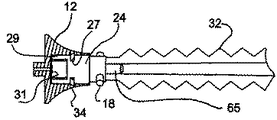
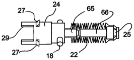
図5および7を参照すると、キャップ・アダプタ24は、シース22に対して密封するための中空の管状突起65を有する。さらに、キャップ・アダプタ24は、1対の外側に向けた移動止め27、および以下に記載する目的のための1対の長手方向の延長部29を有する。
With reference to FIGS. 5 and 7, the
図6および7を参照すると、以下に説明する目的のため、ハウジング・アダプタ25は、シース22に固定するための中空の管状突起66、ならびに外側に向けたスプリング式移動止め28を有する。
6 and 7, for purposes described below, the
図11を参照すると、キャップ12は、成形プラスチックでできており、図12で示したように、キャップ・アダプタ24の移動止め27を受けるための1対の側部開口34を対向する側部に有している。キャップ12は、中心孔33を備えた中心ハブも有して、針11の通過を可能にしている(図1を参照)。
Referring to FIG. 11, the
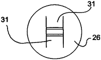
図12を参照すると、スプリング・クリップ26の形状の手段が、キャップ12内に配置され、図9および10で示したように、垂直の壁47に対して、キャップ12の中心孔46内に嵌められている。クリップ26は、「H形」クリップの形状であり、中心開口の外側に向けた1対のスプリングで偏倚されたリーフ31を有している。
Referring to FIG. 12, a means in the form of a
図12を参照すると、キャップ・アダプタ24は、キャップ12内に嵌められて、アダプタ24の移動止め27が、キャップの開口34内にスナップ嵌めされている。同時に、アダプタ24の端部上の延長部29は、スプリング・クリップ26と衝合して、クリップ26を定位置に保持している。移動止め27の位置は、ピン18の位置に関連して、移動止め27が定位置にスナップ嵌めされている場合は、ピン18は、ハウジング13内のスロット19に対して方向付けされている(図1を参照)。
Referring to FIG. 12, the
スプリング・クリップ26は、好ましくは、厚さ0.13mm(5ミル)のステンレス鋼で作成され、H形状をクリップから打ち抜いて、2枚のリーフ31がリーフの間に小さい開口を有するようにする。この開口は、リーフの間に位置する針11に対する摩擦抵抗を低減するのに十分な大きさにし、キャップ12が針11を覆って自由に移動できるようにする。針11をキャップ12内に引込めると、リーフ31は、図10で示した位置まで閉じる。この閉塞は、針11の鋭利な点21がクリップ26を貫通するのを阻止し、それによって針11がキャップ12から出るのを阻止するのに十分である。
The
シース22は、低い破断伸び率、たとえば80%未満を有することを特徴とする。この特性により、シース22が図1の折りたたまれた状態から引き出され、わずかに拡張されて、キャップ12が針11の端部21を越えて延び、スプリング・クリップ26のリーフ31が針11を孔の係止位置に滑り込ませることができる。クリップのリーフ31が、孔33を覆った後、キャップ12は伸ばしたシート22の力で引き込められることができる。針の端部21がキャップ12内に、かつクリップ26を越えたところにある状態では、キャップ12の近位または遠位への更なる移動が阻止される。したがって、針11の鋭利な先端21は、キャップ12内に閉じ込められる。このとき、安全針を安全に廃棄することができる。
The
図13を参照すると、針11は、ハウジング13の孔61内に嵌められ、適した接着剤62によって定位置に固定されている。針11は、雌ルアー・ロック・ハブ14の先細りの孔16に心合わせされる。雌ルアー・ロック・ハブ14は、ハウジング13を雄ルアー・アダプタ(図示せず)に取り付けて、たとえば注射器への連結を確保する手段を提供する。
Referring to FIG. 13, the
ハウジング13は、図14で示したように、キャップ12のハウジング・アダプタ25を受けるための中心開口63も有する。この目的で、1対の開口64をハウジング13内に設けて、図14で示したように、ハウジング・アダプタ25の移動止め28を受けるようにする。
The
図14を参照すると、キャップ12(図示せず)をハウジング13上に取り付けた場合、ハウジング・アダプタ25は、中心開口63を介した移動中にわずかに圧縮される移動止め28が、開口64と位置合せされるまで、圧力を受けて、ハウジング13の中心開口63内に押し込まれる。この時点で、移動止め28は膨張して開口64を塞ぐ。したがって、ハウジング13とハウジング・アダプタ25の間の係止が行われ、それによって、取り付けたシース22をアダプタ25を介してハウジング13に固定する。図で示したように、シース22は、中心開口63内で圧縮され、または波形にたたまれて配置される。図を見やすくするために、針11を図14から省いてある。
Referring to FIG. 14, when the cap 12 (not shown) is mounted on the
図15を参照すると、キャップ12を定位置に取り付けた場合、針11は、スプリング・クリップ26を通過し、リーフは、外側に向けて曲がり、キャップ12を拡張すべきときに、針11に沿ってスライドする。
Referring to FIG. 15, when the
図16を参照すると、キャップ12が針の鋭利な端部を越えて延びる場合、スプリング・クリップ26のリーフは、内向きに曲がり、それによって孔33を閉塞して、針が孔33を介して再び出るのを阻止する。
Referring to FIG. 16, when the
図17を参照すると、アダプタ24、25、およびシース22は、1つのユニットとして扱うことができるアセンブリを形成している。図で示した状態では、アダプタ24、25の管状の延長部65、66が、互いに衝合し、シース22がアダプタ24と25の間の空間内で折りたたまれている。このアセンブリは、針11を覆って配置され、図14で示したように、ハウジング13内にスライドして入り、定位置に確保される。この時点で、キャップ12は、針11と心合わせされる。次いで、鈍端のカニューレ(図示せず)を遠位部分からキャップ12を介して位置させ、クリップ26を鈍端のカニューレ上を移動させてリーフ26を開ける。次いで、針11を、鈍端のカニューレ内に位置させ、次いで、鈍端のカニューレを移動して、針11がクリップ26内にあり、キャップ12を針11に沿ってハウジング13に向けて移動することができるようにする。キャップ12を針11に沿って、アダプタの延長部29と接触するまで移動させる。延長部29は、針11の軸に垂直のクリップ26と位置合せされる傾向がある。次いで、キャップ12をハウジング13内に押し込んで、シース22の成形中に予め方向付けした移動止め27、28が圧縮されるようにする。各移動止め27、28が、それぞれ開口34、64内にスナップ嵌めされた場合、アダプタ24、25は、それぞれキャップ12およびハウジング13内に係止される。同時に、キャップ12のピン18は、ハウジング13のへこみ19内に入る。キャップ12を、たとえば反時計回りに約45°回転すると、キャップ12がハウジング13内に固定される。
Referring to FIG. 17,
使用の際は、通常、針11の鋭利な端部21が保存中に損傷されないように保護するキャップ(図示せず)を取り除き、それによって図1で示したように、アセンブリを露出する。このアセンブリは、注射器、案内ワイヤ、または同様の部品に結合して使用することができるが、そうしなくてもよい。このとき、針11は、患者の皮膚を貫通し、正常に血管に入る。注入後、案内ワイヤの配置などの後、針を患者から引き抜くことができる。使用の一指示では、このときキャップ12を反時計回りに回転して、キャップ12をハウジング17から解放する。次いで、キャップ12を拡張位置に移動し、針を患者から外したときに、キャップ12が針の鋭利な端部21を閉じ込める。この位置で、アセンブリを、針に刺される心配なく廃棄することができる。
In use, the cap (not shown) that normally protects the
同様の参照番号が上記と同様の部分を示す、図18を参照すると、シース41は、先細りまたは円すい形の外側壁42および内側壁43を備えた、先細りまたは円すい形の形状に成形することができる。
Referring to FIG. 18, where like reference numbers indicate like parts, the
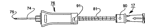
図19を参照すると、注射器アセンブリ70は、一端に、フラッシュ・チャンバ73を画定する雌ルアー・ハブ72を有するハウジング71を備えている。上記のように、鋭利な端部75を備えた針74は、ハウジング71内に固定して取り付けられ、フラッシュ・チャンバ73と流体連通する。
Referring to FIG. 19, the syringe assembly 70 includes a
注射器アセンブリ70は、ハウジング71上に摺動可能に取り付けられたキャップ76も有する。この実施例では、キャップ76は、針74を覆って同心状に配置されたヘッド77、およびヘッド77からハウジング71を越えて延びる細長いスリーブ78を有する。ヘッド77およびスリーブ78は、接着または超音波溶接など、任意の適した方法で互いに固定されている。
The syringe assembly 70 also has a
図で示したように、スリーブ78は、ハウジング71上の管状フランジ79に対して衝合して、引込めた位置に配置される。
As shown, the
ハウジング71は管状の延長部80を有しており、延長部80の上に上記に記載した材料でできたシース81の一端が、同心状に取り付けられている。図で示したように、適した接着剤82を提供して、シース81の端部をハウジング71に、管状の延長部80の周りで密封して固定する。
The
シース81の反対側の端部は、ヘッド77の管状の延長部83上に、適した接着剤または他の適した密封技法で取り付けられている。ヘッド77は、スリーブ78内に摺動可能に受けられるサイズである。さらに、ヘッド77は、半径方向に外側に向けられたポスト85を有し、ポスト85上にスプリング・クリップ86が取り付けられている。
The opposite end of the
図22で示したように、スプリング・クリップ86は、ポスト85を通過させるための孔86’を有しており、図19で示したように、針74に対して押し付けるための丸みを付けた端部87を有するリーフを備えたL形をしている。
As shown in FIG. 22, the
ヘッド77は、中心孔88を有しており、その孔を介して針74が通過する。さらに、スプリング・クリップ86のリーフは、孔88を覆って配置され、以下に記載するように、その孔を介して針が出ないように阻止するサイズである。
The
図23を参照すると、スプリング・クリップ86aは、示したような丸みを付けず、孔86a’を備えて成形することができる。
Referring to FIG. 23, the
注射器アセンブリ70を組み立てるには、シース81をヘッド77の管状延長部83上に取り付ける。次いで、スプリング・クリップ86を、ヘッド77上に配置されたポスト85に取り付ける。次いで、ヘッド77をスリーブ78内に挿入し、定位置に接着する。
To assemble the syringe assembly 70, the
次いで、針74を中心孔88を介してヘッド77内に、シース81を介してハウジング71内に挿入する。次いで、針74をハウジング71に接着または他の方法で固定する。
Next, the
その後、シース81をハウジング71の延長部80に接着する。
Thereafter, the
次いで、スリーブ78をハウジング71上で、環状フランジ79と衝合するまでスライドさせる。図30で示したように、ハウジング71に、ポスト90を設けて、キャップ76内のL形スロット91内に嵌めて、バヨネット式連結を形成し、キャップ76をハウジング71に固定する。
The
使用の際は、針74を患者から引き抜いた場合、キャップ76をハウジング71からスライドして外し、針74上を移動させる。針の鋭利な端部75を患者から引き抜いたとき、図20で示したように、キャップ76を針の端部75を越えて移動させる。図20では、同様の参照番号は、上記と同様の部分を示す。この時点で、スプリング・クリップ86のリーフは、前方にスナップ嵌まりして、ヘッド77の孔88を覆う。
In use, when the
図21を参照すると、針74を前方に移動させても、スプリング・クリップ86がキャップ76のヘッド77の中心孔88を介して再び出るのを阻止するようになっている。
Referring to FIG. 21, even if the
同様の参照番号が上記と同様の部分を示す、図24を参照すると、ヘッド77を変更し、細長い管状の突起83’を有して、針74がシース81と接触せずに、前方に移動し、また引込められることができるようにし、それによって、針74とシース81の摩擦接触を全て回避できるようになされている。
Referring to FIG. 24, like reference numerals indicate like parts as described above, the
同様の参照番号が上記と同様の部分を示す、図25、26、および27を参照すると、針74’は、案内ワイヤ89(図26を参照)と協働する誘導針でもよい。この実施例では、誘導針74を先ず患者から、図25で示した位置から、図26で示した位置に引き込める。その後、案内ワイヤ89を患者から引込め、図27で示したように、リーフ・スプリング85が、孔88を覆って戻りスナップ嵌まりするまで、十分な範囲でキャップ76内に移動させ、それによって、誘導針74’または案内ワイヤ89が再び出るのを阻止する。
Referring to FIGS. 25, 26, and 27, where like reference numbers indicate like parts, the needle 74 'may be a guide needle that cooperates with a guide wire 89 (see FIG. 26). In this embodiment, the
同様の参照番号が上記と同様の部分を示す、図28、29、および30を参照すると、上記に記載したのと同様のバヨネット式係止連結部を使用して、キャップ76をハウジング71上に取り付けることができる。この実施例では、ハウジング71に1対のポスト90(その1つだけが示されている)が設けられ、キャップのスリーブ78は、1対のL形溝91を有し、各溝91はハウジング71のポスト90を受けるように配置されている。キャップ76を解放するには、キャップ76を図28で示した位置から、図29で示した位置まで回転し、ハウジング71から軸方向に引っ張る。次いで、キャップ76をシース81の完全に拡張した位置まで拡張して(図30)、針74の端部75を覆って閉塞させる。
Referring to FIGS. 28, 29, and 30, where like reference numbers indicate like parts, the
同様の参照番号が上記と同様の部分を示す、図31を参照すると、針アセンブリは、生検針として構成することができる。この場合、ハウジング71’は従来の方法で構成されるため、さらに詳細に記載する必要はない。 Referring to FIG. 31, where like reference numbers indicate like parts, the needle assembly can be configured as a biopsy needle. In this case, the housing 71 'is constructed in a conventional manner and need not be described in further detail.
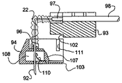
同様の参照番号が上記と同様の部分を示す、図32、33、および34を参照すると、このシース22は、Huber針92に特に有用である。この実施例では、シース22は、ハウジング93とキャップ94の間で延びている。
With reference to FIGS. 32, 33, and 34, where like reference numbers indicate like parts, the
図35を参照すると、Huber針92は、L形の構成で、ハウジング93内に固定された近位のレッグを有している。針92の第2のレッグは、キャップ94を介して延びている。
Referring to FIG. 35, the
キャップ94は、通常の閉塞構造のものであり、針92のレッグに沿って、図32で示した位置から図34で示した位置まで、摺動可能である。キャップ94は、針92を通過させるための孔95を備えており、図35で示した位置から図37で示した位置まで可動である。キャップ94は、管状延長部96を備え、延長部96上にシース22が上記に記載した方法で固定されている。同様に、図35および38で示したように、シース22の反対側の端部は、ハウジング93内に取り付けられた(たとえば塩化ビニル樹脂の)管路98から延びる(たとえば塩化ビニル樹脂の)管状ブッシング97に固定されている。図で示したように、管状ブッシング97は、針92を取り付け、針92を管路98と連通させる。図32で示したように、クリップ99を管路98上に配置して、管路98を介した流体の流れを制御することができる。
The
図35および39を参照すると、キャップ94およびハウジング93は、キャップ94がハウジング93内にスナップ嵌め式に嵌められて、1つのユニットとして扱われるように構成されている。この目的で、ハウジング93は、凹部100を有し、キャップ94はこの凹部100内に嵌まる延長部101を有する。さらに、図39で示したように、小さい肩102が、ハウジング93の凹部100の入口に設けられ、キャップの延長部101は、その突起102を受けるための小さい凹部103を有する。これに関して、キャップ94の延長部101がハウジング93の凹部100内に嵌められた場合、延長部101は、突起102を越えてスナップ嵌まりし、したがってスナップ嵌め式に定位置に保持される。キャップ94をハウジング93から分離させるには、ハウジング93およびキャップ94をそれぞれ手で把持して分離させる。
Referring to FIGS. 35 and 39, the
図40を参照すると、キャップ94は、プラスチック材料で作成され、チャンバ108を画定する複数の壁104、105、106、107を予め備えて成形される。図で示したように、壁の1つの107は、底壁104から間隔を置いた第1の成形位置から、チャンバ108を閉塞するための底壁104に対して密封関係の第2の垂直の位置まで可動である。これに関して、可動の壁107は、固定された底壁104内のスロット109内にスナップ嵌めできる薄くした端部107’を有する。
Referring to FIG. 40, the
図40で示したように、可動壁107は、スプリング・クリップ110を担持する。スプリング・クリップ110は、可動壁107が閉じた位置(図37)に移動した場合に、底壁104内の孔95を覆って延びるサイズである。
As shown in FIG. 40, the
壁107を移動可能にすると、そうでなければ閉塞されているチャンバ108内の定位置に、スプリング・クリップ110を取り付けることができるようになる。
Making the
図37を参照すると、キャップ94は、対向する側に1対のトラック(溝)111が設けられて、ハウジング93の対応するレール(図示せず)または突出する耳(図示せず)を受けるようになっている。
Referring to FIG. 37, the
同様の参照番号が上記と同様の部分を示す、図41および42を参照すると、キャップ94を細長い本体として成形して、ハウジング93の2つの耳112の間でスライドさせることができる。さらに、位置合わせトラック111’を耳112内に位置させ、協働するレール113をキャップ94上に配置することができる。また、キャップ94の下側に、1対の外側に向けた可撓性材料でできた翼114が設けられ、ハウジング93の下側に1対の外側に向けた翼115が設けられている。
Referring to FIGS. 41 and 42, where like reference numbers indicate like parts, the
このHuber針アセンブリを使用するには、ハウジング93およびキャップ94を図43で示したように操作して、針92の露出された端部が、患者の皮下組織116を通って、組織116の下にある注入口117など、薬物送達デバイス内に貫通できるようにする。キャップ94は、指の圧力を与えて、針92を入口117内に押出すことができるようにするのに特に有用である。
To use this Huber needle assembly, the
図44を参照すると、Huber針92を取り外すことが望まれる場合に、組織116に接触して置かれているキャップ94上の翼114を患者に対して押し付けて、キャップ94を定位置に保持する。その後、ハウジング93をキャップ94から垂直方向に持ち上げ、それによって、針92を注入口117の外に、かつ患者から外に引っ張る。この間、シース22は、折りたたまれた状態から拡張した状態に拡張される。
Referring to FIG. 44, when it is desired to remove the
シース22の可撓性の性質のため、図36で示したように、シース22はハウジング93から容易に引き出され、引き裂き、またはハウジング93をキャップ94から離そうとする動きなしで、図37および44で示したように、完全に拡張した状態に拡張される。針92が図37で示した位置に移動した後、スプリング・クリップ110は、孔95を覆って、キャップ94内にスナップ嵌まりして、針92が再び出るのを阻止する。さらに、キャップ94内のチャンバ108は閉塞されているため、針92の端部は密封され閉塞された無菌状態で保持される。この時点で、Huber針アセンブリを、針92が保護されたままで廃棄することができる。
Because of the flexible nature of the
したがって、本発明は、使用後に針を閉じ込めて、不慮の「穿刺」から保護する、簡単な構造を提供するものである。シースに取り付けたキャップと共に針を取り囲む可撓性管状シースの使用は、様々なタイプの針の鋭利な端部を、密封したチャンバ内に閉じ込めることができるようにする。シースを透明な材料で作成した場合は、容器内の針を容易に見ることができ、針が折れているかどうかを判断することができる。 Thus, the present invention provides a simple structure that traps the needle after use and protects it from accidental “puncture”. The use of a flexible tubular sheath that surrounds the needle with a cap attached to the sheath allows the sharp ends of various types of needles to be confined within a sealed chamber. When the sheath is made of a transparent material, the needle in the container can be easily seen and it can be determined whether the needle is broken.
さらに、本発明は、使用後にHuber針の鋭利な端部を閉じ込めるために使用することができる比較的簡単な構造を提供するものである。 Furthermore, the present invention provides a relatively simple structure that can be used to confine the sharp end of a Huber needle after use.
本発明は、活動化の前に、キャップを針の鋭利な端部を覆って配置する、ポジティブロックの特徴、ならびに針の鋭利な先端が保護シースから出るのを阻止する独特のポジティブロックも提供する。 The present invention also provides a positive lock feature that places the cap over the sharp end of the needle prior to activation, as well as a unique positive lock that prevents the sharp tip of the needle from exiting the protective sheath To do.
10 注射器アセンブリ
11 針
12 キャップ
13 ハウジング
14 雌ルアー・ハブ
15 ねじ
16 先細りの孔
18 ピン
19 スロット
21 鋭利な端部
22 シース
23 細片
23’ 支持体
24 キャップ・アダプタ
25 ハウジング・アダプタ
26 スプリング・クリップ
27、28 移動止め
29 延長部
31 リーフ
33 中心孔
34 側部の開口
35、36 相当直径
41 シース
42 外側壁
43 内側壁
46 中心孔
47 壁
61 孔
62 接着剤
63 中心開口
64 開口
65 突起
66 突起
70 注射器アセンブリ
71、71’ ハウジング
72 雌ルアー・ハブ
73 フラッシュ・チャンバ
74 針
74’ 誘導針
75 鋭利な端部
76 キャップ
77 ヘッド
78 スリーブ
79 フランジ
80 延長部
81 シース
82 接着剤
83 延長部
83’ 突起
85 ポスト
86 スプリング・クリップ
86’、86a’ 孔
86a スプリング・クリップ
87 丸みを付けた端部
88 中心孔
89 案内ワイヤ
90 ポスト
91 L形スロット
92 針
93 ハウジング
94 キャップ
95 孔
96 管状延長部
97 管状ブッシング
98 管路
99 クリップ
100 凹部
101 延長部
102 突起
103 凹部
104、105、106、107 壁
107’ 端部
108 チャンバ
109 スロット
110 スプリング・クリップ
111、111’ トラック
112 耳
113 レール
114、115 翼
116 皮下組織
117 注入口
DESCRIPTION OF SYMBOLS 10
Claims (9)
Applications Claiming Priority (1)
| Application Number | Priority Date | Filing Date | Title |
|---|---|---|---|
| US10/320,168 US8066678B2 (en) | 2001-12-17 | 2002-12-16 | Safety needle with collapsible sheath |
Publications (2)
| Publication Number | Publication Date |
|---|---|
| JP2004195227A JP2004195227A (en) | 2004-07-15 |
| JP4355567B2 true JP4355567B2 (en) | 2009-11-04 |
Family
ID=32392974
Family Applications (1)
| Application Number | Title | Priority Date | Filing Date |
|---|---|---|---|
| JP2003416415A Expired - Fee Related JP4355567B2 (en) | 2002-12-16 | 2003-12-15 | Safety needle with foldable sheath |
Country Status (5)
| Country | Link |
|---|---|
| US (3) | US8066678B2 (en) |
| EP (1) | EP1430921B1 (en) |
| JP (1) | JP4355567B2 (en) |
| AT (1) | ATE471175T1 (en) |
| DE (1) | DE60332989D1 (en) |
Cited By (7)
| Publication number | Priority date | Publication date | Assignee | Title |
|---|---|---|---|---|
| US8066678B2 (en) | 2001-12-17 | 2011-11-29 | Bard Access Systems, Inc. | Safety needle with collapsible sheath |
| US8231582B2 (en) | 2008-12-11 | 2012-07-31 | Bard Access Systems, Inc. | Device for removing a Huber needle from a patient |
| US8574197B2 (en) | 2004-02-26 | 2013-11-05 | C. R. Bard, Inc. | Huber needle safety enclosure |
| US8597253B2 (en) | 2007-04-20 | 2013-12-03 | Bard Access Systems | Huber needle with safety sheath |
| US9248234B2 (en) | 2010-09-10 | 2016-02-02 | C. R. Bard, Inc. | Systems for isolation of a needle-based infusion set |
| US10525234B2 (en) | 2010-09-10 | 2020-01-07 | C. R. Bard, Inc. | Antimicrobial/haemostatic interface pad for placement between percutaneously placed medical device and patient skin |
| US10729846B2 (en) | 2010-09-10 | 2020-08-04 | C. R. Bard, Inc. | Self-sealing pad for a needle-based infusion set |
Families Citing this family (133)
| Publication number | Priority date | Publication date | Assignee | Title |
|---|---|---|---|---|
| US6984213B2 (en) * | 2001-03-15 | 2006-01-10 | Specialized Health Products, Inc. | Biopsy needle device |
| US7413562B2 (en) | 2001-03-15 | 2008-08-19 | Specialized Health Products, Inc. | Safety shield for medical needles |
| US6902546B2 (en) * | 2001-03-15 | 2005-06-07 | Specialized Health Products, Inc. | Safety shield for medical needles |
| US7004927B2 (en) * | 2001-03-15 | 2006-02-28 | Specialized Health Products, Inc. | Safety shield for medical needles |
| US7179244B2 (en) * | 2001-03-15 | 2007-02-20 | Specialized Health Products, Inc. | Resettable safety shield for medical needles |
| US6595955B2 (en) * | 2001-03-15 | 2003-07-22 | Specialized Health Products, Inc. | Safety shield for medical needles |
| US6796962B2 (en) * | 2001-03-15 | 2004-09-28 | Specialized Health Products, Inc. | Safety shield for medical needles |
| US6623458B2 (en) * | 2001-09-26 | 2003-09-23 | B. Braun Melsungen, Ag | Spring launched needle safety clip |
| US7458954B2 (en) * | 2002-11-07 | 2008-12-02 | Specialized Health Products, Inc. | Safety shield for medical needles |
| EP1475113A1 (en) * | 2003-05-08 | 2004-11-10 | Novo Nordisk A/S | External needle inserter |
| JP4509100B2 (en) * | 2003-05-08 | 2010-07-21 | ノボ・ノルデイスク・エー/エス | Infusion device attachable to skin with removable needle insertion actuation |
| EP1624914B1 (en) * | 2003-05-08 | 2008-04-16 | Novo Nordisk A/S | Internal needle inserter |
| EP1502613A1 (en) * | 2003-08-01 | 2005-02-02 | Novo Nordisk A/S | Needle device with retraction means |
| KR20060099520A (en) * | 2003-10-21 | 2006-09-19 | 노보 노르디스크 에이/에스 | Medical skin mountable device |
| BRPI0416359B8 (en) * | 2003-11-13 | 2021-06-22 | Specialized Health Products Inc | medical needle safety device |
| US6997902B2 (en) | 2003-11-13 | 2006-02-14 | David L. Thorne | Safety shield for medical needles |
| US8096973B2 (en) * | 2003-11-25 | 2012-01-17 | Specialized Health Products, Inc. | Resettable safety shield for medical needles |
| US20050119627A1 (en) * | 2003-12-01 | 2005-06-02 | Becton, Dickinson And Company | Selectively passive forward shielding medical needle device |
| BRPI0506836B8 (en) * | 2004-01-28 | 2021-06-22 | Specialized Health Products Inc | medical needle protection device |
| EP1732626A1 (en) * | 2004-03-30 | 2006-12-20 | Novo Nordisk A/S | Actuator system comprising lever mechanism |
| FR2869806B1 (en) * | 2004-05-07 | 2007-04-27 | Perouse Soc Par Actions Simpli | INJECTION DEVICE WITH EXTRACTION MECHANISM |
| JP4544943B2 (en) * | 2004-08-26 | 2010-09-15 | 川澄化学工業株式会社 | Curved needle with wings |
| US20080215006A1 (en) * | 2004-09-22 | 2008-09-04 | Novo Nordisk A/S | Medical Device with Transcutaneous Cannula Device |
| US20090012472A1 (en) * | 2004-09-22 | 2009-01-08 | Novo Nordisk A/S | Medical Device with Cannula Inserter |
| US7905857B2 (en) | 2005-07-11 | 2011-03-15 | Covidien Ag | Needle assembly including obturator with safety reset |
| US7850650B2 (en) | 2005-07-11 | 2010-12-14 | Covidien Ag | Needle safety shield with reset |
| US7828773B2 (en) | 2005-07-11 | 2010-11-09 | Covidien Ag | Safety reset key and needle assembly |
| US20090048563A1 (en) * | 2004-12-06 | 2009-02-19 | Novo Nordisk A/S | Ventilated Skin Mountable Device |
| US20060149131A1 (en) * | 2005-01-05 | 2006-07-06 | Sightline Technologies Ltd. | Surgical tool for endoscope |
| JP2008528087A (en) * | 2005-01-24 | 2008-07-31 | ノボ・ノルデイスク・エー/エス | Skin puncture device assembly |
| US20080319387A1 (en) * | 2005-02-14 | 2008-12-25 | Shai Amisar | Method and Apparatus for Inserting a Catheter Device |
| US20080188810A1 (en) * | 2005-02-25 | 2008-08-07 | Novo Nordisk A/S | Pump Assembly With Safety Valve |
| DE102005015801A1 (en) * | 2005-04-06 | 2006-10-19 | Schreiner Group Gmbh & Co. Kg | Foil-based protection mechanism |
| WO2006120253A2 (en) * | 2005-05-13 | 2006-11-16 | Novo Nordisk A/S | Medical device adapted to detect disengagement of a transcutaneous device |
| US20060276772A1 (en) * | 2005-06-06 | 2006-12-07 | Sherwood Services Ag | Bayonet release of safety shield for needle tip |
| US20060276747A1 (en) * | 2005-06-06 | 2006-12-07 | Sherwood Services Ag | Needle assembly with removable depth stop |
| US7731692B2 (en) | 2005-07-11 | 2010-06-08 | Covidien Ag | Device for shielding a sharp tip of a cannula and method of using the same |
| US7654735B2 (en) | 2005-11-03 | 2010-02-02 | Covidien Ag | Electronic thermometer |
| US8688198B2 (en) * | 2005-11-22 | 2014-04-01 | Suros Surgical Sytems, Inc. | Surgical site marker delivery system |
| US9173992B2 (en) * | 2006-03-13 | 2015-11-03 | Novo Nordisk A/S | Secure pairing of electronic devices using dual means of communication |
| JP2009529930A (en) * | 2006-03-13 | 2009-08-27 | ノボ・ノルデイスク・エー/エス | Medical system with bi-purpose communication means |
| CN101426542A (en) * | 2006-04-26 | 2009-05-06 | 诺沃-诺迪斯克有限公司 | Skin-mountable device in packaging comprising coated seal member |
| US7722569B2 (en) * | 2006-05-22 | 2010-05-25 | Becton, Dickinson And Company | Catheter assembly with tip shield closure |
| CN101460207B (en) * | 2006-06-06 | 2012-03-21 | 诺沃-诺迪斯克有限公司 | Assembly comprising skin-mountable device and packaging therefore |
| JP4994775B2 (en) | 2006-10-12 | 2012-08-08 | 日本コヴィディエン株式会社 | Needle point protector |
| US9220871B2 (en) * | 2006-11-22 | 2015-12-29 | Becton, Dickinson And Company | Needle shielding pawl structures |
| US9056188B2 (en) * | 2006-11-22 | 2015-06-16 | Becton, Dickinson And Company | Needle shielding flag structures |
| US7625207B2 (en) * | 2006-12-15 | 2009-12-01 | Kimberly-Clark Worldwide, Inc. | Yankauer suction device with sleeve and wiper |
| WO2008107467A1 (en) * | 2007-03-06 | 2008-09-12 | Novo Nordisk A/S | Pump assembly comprising actuator system |
| WO2008109845A2 (en) * | 2007-03-07 | 2008-09-12 | Becton, Dickinson And Company | Safety blood collection assembly with indicator |
| US8888713B2 (en) | 2007-03-07 | 2014-11-18 | Becton, Dickinson And Company | Safety blood collection assembly with indicator |
| EP2188004A4 (en) * | 2007-08-21 | 2015-06-17 | Yukon Medical Llc | Vial access and injection system |
| EP2209500B1 (en) * | 2007-10-31 | 2015-07-22 | Novo Nordisk A/S | Non-porous material as sterilization barrier |
| US8357104B2 (en) | 2007-11-01 | 2013-01-22 | Coviden Lp | Active stylet safety shield |
| JP5432172B2 (en) | 2007-11-21 | 2014-03-05 | ベクトン・ディキンソン・アンド・カンパニー | Safety needle guard |
| ES2788079T3 (en) | 2007-11-21 | 2020-10-20 | Becton Dickinson Co | Needle safety device |
| US8603009B2 (en) | 2008-03-07 | 2013-12-10 | Becton, Dickinson And Company | Flashback blood collection needle |
| US8795198B2 (en) * | 2008-03-07 | 2014-08-05 | Becton, Dickinson And Company | Flashback blood collection needle |
| CN101980745A (en) * | 2008-03-31 | 2011-02-23 | 泰尔茂株式会社 | Indwelling needle assembly |
| US20110152782A1 (en) * | 2008-04-23 | 2011-06-23 | Gary Christopher Jones | Cover for the tip of a sharp medical device |
| US20110066107A1 (en) * | 2008-05-14 | 2011-03-17 | John Stephens | Needle protective device |
| US7811261B2 (en) | 2008-06-02 | 2010-10-12 | Sta-Med, Llc | Needle cover assembly for a syringe |
| US20100010450A1 (en) * | 2008-06-13 | 2010-01-14 | Vincent Runfola | Retractable syringe with improved stem ring and needle interchangeability |
| GB0821492D0 (en) * | 2008-11-25 | 2008-12-31 | Team Holdings Uk Ltd | Integrated auto-injector cartridge system |
| CN101601882B (en) * | 2009-07-15 | 2012-02-01 | 无锡市宇寿医疗器械股份有限公司 | Disposable safety syringe with replaceable and automatically retracted needle |
| EP2459255B1 (en) * | 2009-07-31 | 2019-04-03 | Medical Components, Inc. | Huber needle with safety tube |
| US8323249B2 (en) | 2009-08-14 | 2012-12-04 | The Regents Of The University Of Michigan | Integrated vascular delivery system |
| EP2501288B1 (en) * | 2009-11-19 | 2016-12-21 | Modulated Imaging Inc. | Method and apparatus for analysis of turbid media via single-element detection using structured illumination |
| EP2550046B1 (en) * | 2010-03-23 | 2019-04-24 | Hyperbranch Medical Technology, Inc. | Disposable syringe applicators for multi-component formulations |
| US20120004619A1 (en) * | 2010-03-31 | 2012-01-05 | Stephens John D | Needle protective device |
| WO2011146769A2 (en) | 2010-05-19 | 2011-11-24 | Tangent Medical Technologies Llc | Integrated vascular delivery system |
| WO2011146772A1 (en) | 2010-05-19 | 2011-11-24 | Tangent Medical Technologies Llc | Safety needle system operable with a medical device |
| US8162882B2 (en) | 2010-06-23 | 2012-04-24 | Sta-Med, Llc | Automatic-locking safety needle covers and methods of use and manufacture |
| WO2012013662A1 (en) * | 2010-07-26 | 2012-02-02 | Steerable Instruments Bvba | Capillary tube assembly |
| EP2608825B1 (en) | 2010-08-27 | 2014-08-13 | Novo Nordisk A/S | Medical injection device |
| FR2964571B1 (en) * | 2010-09-10 | 2013-06-21 | Mc2T | NEEDLE SECURING DEVICE FOR MEDICAL USE |
| EP2510964A1 (en) * | 2011-04-11 | 2012-10-17 | Becton Dickinson France | Needle assembly and injection device with foldable needle protecting means |
| EP2517751B8 (en) | 2011-04-27 | 2018-02-28 | Kpr U.S., Llc | Safety IV catheter assemblies |
| WO2012152705A1 (en) * | 2011-05-06 | 2012-11-15 | Sanofi-Aventis Deutschland Gmbh | Ring center needle |
| WO2012166746A1 (en) | 2011-05-31 | 2012-12-06 | Sta-Med, Llc | Blood collection safety devices and methods of use and manufacture |
| GB201109620D0 (en) * | 2011-06-09 | 2011-07-20 | Ardehali Massoud H | Injection apparatus |
| JP6130377B2 (en) | 2011-09-02 | 2017-05-17 | ユニトラクト シリンジ プロプライエタリイ リミテッドUnitract Syringe Pty Ltd | Insertion mechanism for drug delivery pump |
| US9707335B2 (en) | 2011-09-02 | 2017-07-18 | Unitract Syringe Pty Ltd | Drive mechanism for drug delivery pumps with integrated status indication |
| AU2012301784B2 (en) | 2011-09-02 | 2017-02-16 | Unitract Syringe Pty Ltd | Drive mechanism for drug delivery pumps with integrated status indication |
| US11173244B2 (en) | 2011-09-02 | 2021-11-16 | Unl Holdings Llc | Drive mechanism for drug delivery pumps with integrated status indication |
| US9814832B2 (en) | 2011-09-02 | 2017-11-14 | Unl Holdings Llc | Drive mechanism for drug delivery pumps with integrated status indication |
| US8905944B2 (en) * | 2011-09-07 | 2014-12-09 | Vlv Associates, Inc. | Protective cover assembly for a needle assembly |
| MX352613B (en) | 2011-09-13 | 2017-12-01 | Unitract Syringe Pty Ltd | Sterile fluid pathway connection to drug containers for drug delivery pumps. |
| WO2013048768A1 (en) | 2011-09-26 | 2013-04-04 | Covidien Lp | Safety iv catheter and needle assembly |
| WO2013048975A1 (en) | 2011-09-26 | 2013-04-04 | Covidien Lp | Safety catheter |
| EP2766074B1 (en) | 2011-10-14 | 2020-04-08 | Kpr U.S., Llc | Safety iv catheter assembly |
| EP2776098B1 (en) | 2011-11-07 | 2020-03-04 | Safety Syringes, Inc. | Contact trigger release needle guard |
| DE102012102519A1 (en) | 2012-03-23 | 2013-09-26 | Pfm Medical Ag | Safety pin device, in particular for puncturing a subcutaneously implanted port in a human or animal body |
| US10278676B2 (en) * | 2012-06-27 | 2019-05-07 | Michael J. Vaillancourt | Safety shield for a needle assembly |
| CN104582755B (en) | 2012-08-29 | 2017-12-01 | 尤尼特拉克特注射器控股有限公司 | Controlled transport driving for medicine transportation pump |
| JP5748716B2 (en) * | 2012-09-06 | 2015-07-15 | ブイエルブイ アソシエイツ、インコーポレイテッド | Protective cover assembly for needle assembly |
| ES2728428T3 (en) | 2012-10-05 | 2019-10-24 | Medikit Co Ltd | Medical safety needle that prevents re-exposure of the needle tip |
| MX361943B (en) | 2012-11-07 | 2018-12-19 | Modulated Imaging Inc | Efficient modulated imaging. |
| IL281709B (en) | 2013-01-25 | 2022-07-01 | Unitract Syringe Pty Ltd | Integrated sliding seal fluid pathway connection and drug containers for drug delivery pumps |
| USD723157S1 (en) | 2013-03-12 | 2015-02-24 | Unitract Syringe Pty Ltd | Drug delivery pump |
| US20150360005A1 (en) * | 2013-01-30 | 2015-12-17 | Equipos Médicos Vizcarra, S.A. | Peripheral intravenous catheter with bellows-type passive safety system ivcbts |
| MX2013001219A (en) * | 2013-01-30 | 2014-07-30 | Equipos Médicos Vizcarra S A | Closed peripheral intravenous catheter with safety system cpivcss. |
| US10350366B2 (en) | 2013-02-01 | 2019-07-16 | Nxstage Medical, Inc. | Safe cannulation devices, methods, and systems |
| IL275793B (en) * | 2013-03-15 | 2022-08-01 | Univ California | Multifrequency signal processing classifiers for determining a tissue condition |
| US9125985B2 (en) | 2013-04-01 | 2015-09-08 | iMed Technology, Inc. | Needle with protective cover member |
| JP6210718B2 (en) * | 2013-05-01 | 2017-10-11 | メディキット株式会社 | How to assemble a medical safety needle |
| CN103405833B (en) * | 2013-08-15 | 2015-06-17 | 王幸明 | Puncture-preventing entry needle |
| WO2015027174A1 (en) | 2013-08-23 | 2015-02-26 | Unitract Syringe Pty Ltd | Integrated pierceable seal fluid pathway connection and drug containers for drug delivery pumps |
| EP3046597B1 (en) * | 2013-09-18 | 2019-03-13 | Alliance Vascular Devices LLC | Medical infusion device and methods of use |
| US10549028B2 (en) * | 2013-09-18 | 2020-02-04 | Alliance Vascular Devices, Llc | Medical infusion device and methods of use |
| MX370463B (en) | 2013-10-10 | 2019-12-13 | Medical Components Inc | Huber needle assembly with safety capture device. |
| KR101503886B1 (en) * | 2013-12-31 | 2015-03-19 | 주식회사 세이퍼위드 | Needle assembly, safety syringe and safety syringe apparatus using the same |
| WO2015115316A1 (en) * | 2014-01-29 | 2015-08-06 | テルモ株式会社 | Catheter assembly |
| AU2015214400B2 (en) | 2014-02-04 | 2019-10-03 | Icu Medical, Inc. | Self-priming systems and methods |
| US10952709B2 (en) | 2014-04-04 | 2021-03-23 | Hyperbranch Medical Technology, Inc. | Extended tip spray applicator for two-component surgical sealant, and methods of use thereof |
| CN106535958A (en) | 2014-07-01 | 2017-03-22 | C·R·巴德股份有限公司 | Antimicrobial/haemostatic interface pad for placement between percutaneously placed medical device and patient skin |
| IL277320B2 (en) | 2014-08-29 | 2023-03-01 | Medical Components Inc | Huber safety needle |
| CN107278158A (en) | 2014-09-29 | 2017-10-20 | 尤尼特拉克特注射器控股有限公司 | Rigid needle interposer for medicine transportation pump |
| GB2529270B (en) * | 2015-01-02 | 2016-07-27 | Becton Dickinson Co | Safety intravenous catheter with friction-based retention and disabling feature |
| USD804022S1 (en) | 2015-02-27 | 2017-11-28 | Medical Components, Inc. | Huber safety needle |
| USD804021S1 (en) | 2015-02-27 | 2017-11-28 | Medical Components, Inc. | Huber safety needle |
| US9919100B2 (en) * | 2015-03-12 | 2018-03-20 | Lexel S.R.L. | Safety needle device |
| WO2017161223A1 (en) | 2016-03-18 | 2017-09-21 | Medical Components, Inc. | Huber safety needle |
| KR101665299B1 (en) * | 2016-07-13 | 2016-10-12 | 최병일 | Medicine thread embedding device |
| MX2019001580A (en) | 2016-08-08 | 2019-06-20 | Unl Holdings Llc | Drug delivery device and method for connecting a fluid flowpath. |
| TW201811385A (en) | 2016-08-30 | 2018-04-01 | 澳洲商優尼揣克注射器有限公司 | Controlled delivery drive mechanisms for drug delivery pumps |
| US10322265B2 (en) * | 2016-10-12 | 2019-06-18 | Mark Leeroy Clarke | Apparatus and method for accessing an epidural space |
| US10973499B2 (en) * | 2017-02-28 | 2021-04-13 | Boston Scientific Scimed, Inc. | Articulating needles and related methods of use |
| KR102034927B1 (en) * | 2017-09-22 | 2019-10-21 | 고경희 | safety syringe with cap |
| IT201800005604A1 (en) * | 2018-05-22 | 2018-08-22 | SAFETY AND FILLING SYSTEM FOR RETRACTABLE NEEDLE SYRINGES | |
| USD884160S1 (en) | 2019-02-25 | 2020-05-12 | iMed Technology, Inc. | Huber safety needle |
| US11724072B2 (en) * | 2019-11-25 | 2023-08-15 | Becton, Dickinson And Company | Devices, systems, and methods to reduce premature needle safety activation |
| CN113384358B (en) * | 2021-05-19 | 2022-05-03 | 四川大学华西医院 | Portable integrative sense of pain physical examination instrument of retrieving |
Family Cites Families (156)
| Publication number | Priority date | Publication date | Assignee | Title |
|---|---|---|---|---|
| US2847995A (en) | 1954-08-23 | 1958-08-19 | Becton Dickinson Co | Transfusion needle sheath |
| US2876770A (en) | 1955-10-10 | 1959-03-10 | Raymond A White | Shielded hypodermic syringe |
| US2925083A (en) | 1957-12-27 | 1960-02-16 | Clarence D Craig | Hypodermic syringe with hood for guarding and concealing the needle |
| US3134380A (en) | 1962-02-08 | 1964-05-26 | Thomas A Armao | Shielded hypodermic needle |
| US3306290A (en) | 1964-02-14 | 1967-02-28 | Harold S Weltman | Automatically retractable needle syringe |
| US4160450A (en) | 1977-07-15 | 1979-07-10 | Doherty George O | Outside-the-needle catheter device with needle housing |
| US4235234A (en) | 1978-11-30 | 1980-11-25 | Martin John K Iii | Subcutaneous injection system |
| US4380234A (en) | 1979-08-16 | 1983-04-19 | Baxter Travenol Laboratories, Inc. | Infusion needle attachment |
| US4352254A (en) | 1980-05-27 | 1982-10-05 | Kurt Peter | Cartridge package for rapid loading of a magazine or clip for automatic and semiautomatic weapons |
| JPS646832Y2 (en) | 1980-10-30 | 1989-02-22 | ||
| US4435175A (en) | 1981-09-11 | 1984-03-06 | Friden G Burton | Infusion needle carrier |
| AU575814B2 (en) * | 1983-03-03 | 1988-08-11 | Bengt Gustavsson | A device for transferring a substance |
| US4611382A (en) | 1984-04-23 | 1986-09-16 | Joule' Inc. | Method for manufacturing a fistula |
| US4655765A (en) | 1984-06-01 | 1987-04-07 | Parker Hannifin Corporation | Fitting with prestressed septum |
| US4627842A (en) | 1984-11-19 | 1986-12-09 | William Katz | Intravenous needle assembly |
| US4615468A (en) | 1985-02-22 | 1986-10-07 | The United States Of America As Represented By The United States Department Of Energy | Gas ampoule-syringe |
| US4632671A (en) | 1985-04-12 | 1986-12-30 | Dalton Michael J | Conduit anchor adapted to receive stylet |
| US4631058A (en) | 1985-06-24 | 1986-12-23 | Burron Medical, Inc. | Guard for right angle winged infusion needle |
| US4627843A (en) | 1985-06-24 | 1986-12-09 | Burron Medical Inc. | Guard for right angle infusion needle |
| US4645495A (en) | 1985-06-26 | 1987-02-24 | Vaillancourt Vincent L | Vascular access implant needle patch |
| US4592744A (en) | 1985-08-14 | 1986-06-03 | The University Of Virginia Alumni Patents Foundation | Self-resheathing needle assembly |
| US4676783A (en) | 1985-09-03 | 1987-06-30 | The University Of Virginia Alumni Patents Foundation | Retractable safety needle |
| US4781692A (en) | 1985-09-03 | 1988-11-01 | The University Of Virginia Alumni Patents Foundation | Retractable safety needles |
| US4710176A (en) | 1985-09-16 | 1987-12-01 | Gish Biomedical, Inc. | Needle device for use with subcutaneous catheter assemblies |
| US4645494A (en) | 1985-10-22 | 1987-02-24 | Renal Systems, Inc. | Peritoneal device system |
| USD301742S (en) | 1986-03-18 | 1989-06-20 | Baxter International Inc. | Winged angular infusion needle |
| US4760847A (en) | 1986-08-18 | 1988-08-02 | Vincent Vaillancourt | Depth measuring device |
| US4820282A (en) | 1986-10-20 | 1989-04-11 | City Of Hope National Medical Center | Sheath for butterfly needles |
| DE3808688A1 (en) | 1987-03-17 | 1989-01-19 | Robert Hagen | Cannula protecting device |
| US4725267A (en) | 1987-05-06 | 1988-02-16 | Vaillancourt Vincent L | Post-injection needle sheath |
| US4935011A (en) | 1987-09-29 | 1990-06-19 | City Of Hope | Sheath for intravenous needle |
| US4813939A (en) | 1987-12-04 | 1989-03-21 | Joel Marcus | Winged infusion apparatus for patient implantable access ports |
| DE3802353A1 (en) | 1988-01-27 | 1989-08-10 | Uwe W Dr Ballies | Safety cannula |
| US4867172A (en) | 1988-02-23 | 1989-09-19 | Habley Medical Technology Corporation | Collapsible blood collector |
| US4935013A (en) | 1988-02-23 | 1990-06-19 | Habley Medical Technology Corporation | Collapsible needle cover |
| US4950250A (en) | 1988-02-23 | 1990-08-21 | Habley Medical Technology Corporation | Collapsible needle cover |
| US4846809A (en) | 1988-02-29 | 1989-07-11 | Winifred Sims | Needle tip protective device |
| US5088982A (en) | 1988-03-01 | 1992-02-18 | Ryan Medical, Inc. | Safety winged needle medical devices |
| US5085639A (en) | 1988-03-01 | 1992-02-04 | Ryan Medical, Inc. | Safety winged needle medical devices |
| GB2217991A (en) | 1988-05-03 | 1989-11-08 | John Cole | Needle protection |
| US5013305A (en) | 1988-06-29 | 1991-05-07 | Opie Eric A | Needle safety system and method |
| JPH03505293A (en) | 1988-09-30 | 1991-11-21 | ウッターバーグ、デビッド,エス | Guarded winged needle assembly |
| US4941881A (en) | 1989-08-23 | 1990-07-17 | Masters Edwin J | IV infusion set with sheath |
| US4969876A (en) | 1989-09-07 | 1990-11-13 | Frank LaVallo | Needle protector |
| FR2658082B1 (en) | 1990-02-15 | 1995-06-09 | Metais Joel | IMPROVEMENTS IN IMPLANTABLE VASCULAR ACCESS DEVICES. |
| US5053017A (en) | 1990-02-28 | 1991-10-01 | Chamuel Steven R | Hypodermic needle safety clip |
| IE911031A1 (en) | 1990-04-03 | 1991-10-23 | Knutson Richard A | Closed system intravenous catheter |
| US5176662A (en) | 1990-08-23 | 1993-01-05 | Minimed Technologies, Ltd. | Subcutaneous injection set with improved cannula mounting arrangement |
| US5061250A (en) | 1990-08-28 | 1991-10-29 | Shields Jack W | Intravenous needle sheathing device |
| US5176655A (en) | 1990-11-08 | 1993-01-05 | Mbo Laboratories, Inc. | Disposable medical needle and catheter placement assembly having full safety enclosure means |
| US5292310A (en) | 1990-12-27 | 1994-03-08 | Inbae Yoon | Safety needle |
| US5120320A (en) | 1991-02-13 | 1992-06-09 | Becton, Dickinson And Company | I.V. infusion or blood collection assembly with automatic safety feature |
| US5092852A (en) | 1991-02-15 | 1992-03-03 | Edward Poling | Safety syringe for single use |
| US5192275A (en) | 1991-09-18 | 1993-03-09 | Becton, Dickinson And Company | IV infusion or blood collection guard assembly |
| IT1251532B (en) | 1991-10-31 | 1995-05-16 | Pasquale Mastronardi | NEEDLE CANNULA PROVIDED WITH SAFETY DEVICE |
| FR2684006B1 (en) | 1991-11-27 | 1998-01-09 | Sarl Gestra | PUNCTURE NEEDLE FOR PERIPHERAL CATHETER. |
| WO1994000172A1 (en) | 1992-06-22 | 1994-01-06 | Wong Henry C C | Automatic disposable needle guard |
| US5295972A (en) | 1992-08-04 | 1994-03-22 | Metatech Corporation | Hypodermic syringe with protective cap |
| US5460878A (en) | 1992-10-26 | 1995-10-24 | Applied Extrusion Technologies, Inc. | Heat sealable shrink laminate |
| SE502537C2 (en) | 1992-11-26 | 1995-11-06 | Boc Ohmeda Ab | Device for infusion cannula |
| US5350368A (en) | 1992-12-17 | 1994-09-27 | Shields Jack W | Tethered butterfly needle trap |
| US5693022A (en) | 1993-05-21 | 1997-12-02 | Haynes-Miller | Protective shield for hypodermic syringe |
| KR960015616B1 (en) | 1993-05-27 | 1996-11-18 | 송경진 | Vein neddle set |
| US5336187A (en) * | 1993-06-24 | 1994-08-09 | Mark Terry | Automatic cover disposable syringe |
| US5312371A (en) | 1993-07-27 | 1994-05-17 | Dombrowski Mitchell P | Method of making a needle sleeve assembly |
| ATE258449T1 (en) | 1993-09-27 | 2004-02-15 | Eastland Tech Australia | ONE INFUSION KIT |
| US5419766A (en) | 1993-09-28 | 1995-05-30 | Critikon, Inc. | Catheter with stick protection |
| US5330438A (en) | 1993-10-08 | 1994-07-19 | Gollobin Peter J | Protective sheath for butterfly needles and IV infusion set and sheath assembly |
| US5334158A (en) | 1993-12-20 | 1994-08-02 | Mclees Donald J | Automatic needle tip guard for standard hypodermic needles |
| JP3245843B2 (en) | 1994-01-21 | 2002-01-15 | ニプロ株式会社 | Indwelling needle with wing |
| US5354281A (en) | 1994-03-25 | 1994-10-11 | Chen Shih Shuan | Safety disposable infusion set |
| ITRE940021A1 (en) | 1994-03-29 | 1995-09-29 | Cgm Spa | IMPROVED NEEDLE HOLDER DEVICE FOR BODY PENETRATION, AS A NEEDLE FOR INFUSIONS, WITHDRAWALS AND SIMILAR USES. |
| US5487728A (en) | 1994-05-19 | 1996-01-30 | Vaillancourt; Vincent L. | Connector assembly |
| US5490841A (en) | 1994-07-29 | 1996-02-13 | Landis; Robert M. | Safety sheath device |
| US5584818A (en) | 1994-08-22 | 1996-12-17 | Morrison; David | Safety hypodermic needle and shielding cap assembly |
| US5487733A (en) | 1994-09-20 | 1996-01-30 | Becton, Dickinson And Company | Assembly with collapsible sheath and tip guard |
| US5885255A (en) | 1994-12-20 | 1999-03-23 | Jaeger, Jr.; Cletus Wilfred | Protective needle cover |
| US5531704A (en) | 1995-03-03 | 1996-07-02 | Emk Enterprises, Llc | Needle puncture prevention device |
| US5674201A (en) | 1995-03-16 | 1997-10-07 | Becton Dickinson And Company | Rotatable catheter housed within a flexible wing assembly |
| US5584813A (en) | 1995-06-07 | 1996-12-17 | Minimed Inc. | Subcutaneous injection set |
| US5853393A (en) | 1995-06-07 | 1998-12-29 | Johnson & Johnson Medical, Inc. | Catheter needle locking and catheter hub unlocking mechanism |
| US5685860A (en) | 1995-06-07 | 1997-11-11 | Johnson & Johnson Medical, Inc. | Self-capping needle assembly |
| US5706520A (en) | 1995-08-15 | 1998-01-13 | The United States Of America As Represented By The Department Of Health And Human Services | Hand puncture protector |
| EP0763369B1 (en) | 1995-09-18 | 2002-01-09 | Becton, Dickinson and Company | Needle shield with collapsible cover |
| FR2740043B1 (en) | 1995-10-20 | 1997-12-12 | M2Ct | DEVICE FOR PROTECTING A HYPODERMIC NEEDLE ON AN INSTRUMENT COMPRISING SUCH A NEEDLE |
| US6238375B1 (en) | 1996-01-02 | 2001-05-29 | Richard R. Powell | Retractable cover extraction for intravenous and other therapy needles |
| US6629959B2 (en) | 1996-02-27 | 2003-10-07 | Injectimed, Inc. | Needle tip guard for percutaneous entry needles |
| US5858004A (en) | 1996-08-19 | 1999-01-12 | Shields; Jack W. | Head projections on shielded butterfly needle assemblies |
| US5779679A (en) | 1997-04-18 | 1998-07-14 | Shaw; Thomas J. | Winged IV set with retractable needle |
| US5817070A (en) | 1997-07-21 | 1998-10-06 | Tamaro; Frank A. | Safety cap assembly for needles |
| US5879330A (en) | 1997-08-08 | 1999-03-09 | Medcare Medical Group, Inc. | Needle removal and containment device and method of using same |
| US8211070B2 (en) | 1997-08-20 | 2012-07-03 | B. Braun Melsungen Ag | Spring clip safety IV catheter |
| US5951525A (en) | 1998-02-10 | 1999-09-14 | Specialized Health Products, Inc. | Manual safety medical needle apparatus and methods |
| US6749588B1 (en) | 1998-04-09 | 2004-06-15 | Becton Dickinson And Company | Catheter and introducer needle assembly with needle shield |
| DE69912269T2 (en) | 1998-05-15 | 2004-08-26 | Device Research & Development (Drd) | DEVICE FOR PROTECTING AND NEUTRALIZING A NEEDLE FOR MEDICAL USE |
| US6355021B1 (en) | 1998-07-14 | 2002-03-12 | Maersk Medical A/S | Medical puncturing device |
| US6689102B2 (en) | 1998-07-31 | 2004-02-10 | Albany Medical College | Safety intravenous catheter assembly |
| US5951522A (en) | 1998-11-05 | 1999-09-14 | Millennium Medical Distribution | Hypodermic needle safety enclosure |
| US6042570A (en) | 1999-02-11 | 2000-03-28 | Dsu Medical Corporation | Needle point protection sheath |
| US6808509B1 (en) | 1999-04-22 | 2004-10-26 | Scimed Life Systems, Inc. | Valved introducer sheath and related methods |
| US6699217B2 (en) | 1999-08-23 | 2004-03-02 | Becton, Dickinson And Company | Safety needle assembly |
| US7198618B2 (en) | 1999-11-04 | 2007-04-03 | Tyco Healthcare Group Lp | Safety shield for medical needles |
| FR2803529B1 (en) | 2000-01-12 | 2002-12-13 | Vygon | ANTI-SPICK DEVICE FOR SAFE HANDLING AN INJECTION NEEDLE |
| US6972002B2 (en) | 2000-04-28 | 2005-12-06 | Specialized Health Products, Inc. | Passively activated safety shield for a catheter insertion needle |
| US7530964B2 (en) | 2000-06-30 | 2009-05-12 | Elan Pharma International Limited | Needle device and method thereof |
| US6537255B1 (en) | 2000-10-09 | 2003-03-25 | B Braun Medical, Inc. | Huber needle with folding safety wings |
| US6659984B2 (en) | 2001-01-05 | 2003-12-09 | Becton Dickinson And Company | Needle assembly |
| US6500155B2 (en) | 2001-02-13 | 2002-12-31 | Churchill Medical Systems, Inc. | Safety angled indwelling needle and a protective shield for a safety angled indwelling needle |
| US7361159B2 (en) | 2001-03-02 | 2008-04-22 | Covidien Ag | Passive safety shield |
| US6761706B2 (en) | 2001-04-04 | 2004-07-13 | Patricia B. Vaillancourt | Needle guard |
| DE20106697U1 (en) | 2001-04-18 | 2001-10-31 | Braun Melsungen Ag | Catheter introducer |
| US6719727B2 (en) | 2001-05-25 | 2004-04-13 | Becton Dickinson And Company | Catheter having a wing with a stiffening member therein |
| US6623462B2 (en) | 2001-05-11 | 2003-09-23 | Harmac Medical Products, Inc. | Needle safety guard |
| US6824530B2 (en) | 2001-05-11 | 2004-11-30 | Harmac Medical Products, Inc. | Combination needle assembly and needle safety guard |
| JP2002345955A (en) | 2001-05-23 | 2002-12-03 | Kazuaki Yamaoka | Injection needle with safety cap |
| US6497669B1 (en) | 2001-06-04 | 2002-12-24 | Rheologics, Inc. | Non-biohazard blood letting system |
| US6623458B2 (en) * | 2001-09-26 | 2003-09-23 | B. Braun Melsungen, Ag | Spring launched needle safety clip |
| US6613015B2 (en) | 2001-10-04 | 2003-09-02 | Deltec, Inc. | Right angle safety needle |
| AU2002335138A1 (en) | 2001-10-24 | 2003-05-06 | Horizon Medical Products, Inc. | Intravascular administration set needle safety device |
| US6783516B2 (en) | 2001-11-13 | 2004-08-31 | Neosurg Technologies, Inc. | Trocar |
| US20030105430A1 (en) | 2001-11-30 | 2003-06-05 | Elan Pharma International Limited Wil House | Automatic injector |
| US8066678B2 (en) | 2001-12-17 | 2011-11-29 | Bard Access Systems, Inc. | Safety needle with collapsible sheath |
| ITTO20011228A1 (en) | 2001-12-28 | 2003-06-28 | Cane Srl | DISPOSABLE NEEDLE CONTAINER. |
| US6926693B2 (en) | 2002-02-04 | 2005-08-09 | Benlan, Inc | Drug delivery needle device |
| DE60304681T2 (en) | 2002-02-12 | 2007-01-25 | Unomedical A/S | INFUSION DEVICE WITH NADELSCHUTZHÜLSE |
| US6918894B2 (en) | 2002-02-28 | 2005-07-19 | Medical Product Specialists | Huber needle with anti-rebound safety mechanism |
| AU2003201340A1 (en) | 2002-03-19 | 2003-10-16 | Becton, Dickinson And Company | Needle device |
| CA2422307A1 (en) | 2002-03-20 | 2003-09-20 | Stefanie Livanos | Blood collection device |
| EP1886710B1 (en) | 2002-06-20 | 2016-12-14 | Becton, Dickinson and Company | Catheter and introducer needle assembly with needle shield |
| DE20210394U1 (en) | 2002-07-04 | 2002-09-12 | Braun Melsungen Ag | catheter introducer |
| US6755805B1 (en) | 2002-09-13 | 2004-06-29 | Alan Reid | Needle device having enhanced safety |
| US6783002B1 (en) | 2002-10-29 | 2004-08-31 | John A. Pavlo | Anti-needlestick system |
| US6921388B2 (en) | 2002-11-04 | 2005-07-26 | Becton Dickinson Co | Needle assembly |
| US6969372B1 (en) | 2003-01-07 | 2005-11-29 | Halseth Thor R | Automatic retraction Huber needle safety enclosure |
| ITMI20032128A1 (en) | 2003-11-05 | 2005-05-06 | High Tech Initiatives Italia S R L | IMPROVEMENTS TO A NEEDLE OF HUBER |
| US6997902B2 (en) | 2003-11-13 | 2006-02-14 | David L. Thorne | Safety shield for medical needles |
| CN2655924Y (en) | 2003-11-17 | 2004-11-17 | 杨章民 | Disposable safety needle protective lid |
| US7309326B2 (en) | 2003-11-18 | 2007-12-18 | Icu Medical, Inc. | Infusion set |
| US7150725B2 (en) | 2003-12-17 | 2006-12-19 | Becton Dickinson And Company | Passive activated safety blood collection set |
| US7776016B1 (en) | 2004-02-26 | 2010-08-17 | C. R. Bard, Inc. | Huber needle safety enclosure |
| EP1740253B1 (en) | 2004-04-30 | 2008-08-13 | C.R.Bard, Inc. | Valved sheath introducer for venous cannulation |
| US7758544B2 (en) | 2004-08-17 | 2010-07-20 | Specialized Health Products, Inc. | Safety shield for medical needles |
| US20090254050A1 (en) | 2004-12-21 | 2009-10-08 | Michael Reinhard Bottcher | Valve |
| US20060161116A1 (en) | 2005-01-19 | 2006-07-20 | Willis Allan F | Protective cover for arterial needle |
| WO2006116613A1 (en) | 2005-04-27 | 2006-11-02 | C.R. Bard, Inc. | Infusion apparatuses |
| ATE406859T1 (en) | 2005-06-13 | 2008-09-15 | Alcon Inc | CANNULA INFUSION SYSTEM |
| US20070038182A1 (en) | 2005-08-08 | 2007-02-15 | Bialecki Dennis M | Needle guard mechanism with needle support |
| US8403886B2 (en) | 2005-08-08 | 2013-03-26 | Smiths Medical Asd, Inc. | Needle guard clip with lip |
| US8251950B2 (en) | 2005-08-08 | 2012-08-28 | Smiths Medical Asd, Inc. | Needle guard clip with heel |
| US8162881B2 (en) | 2005-08-08 | 2012-04-24 | Smiths Medical Asd, Inc. | Needle guard mechanism with angled strut wall |
| US20070078432A1 (en) | 2005-09-06 | 2007-04-05 | Halseth Thor R | Adjustable medication infusion injection apparatus |
| US9186455B2 (en) | 2006-02-14 | 2015-11-17 | B. Braun Medical Inc. | Port access device |
| US20090143737A1 (en) | 2006-05-17 | 2009-06-04 | Terumo Kabushiki Kaisha, | Indwelling needle assembly |
| US8597253B2 (en) | 2007-04-20 | 2013-12-03 | Bard Access Systems | Huber needle with safety sheath |
| US7828774B2 (en) | 2008-05-12 | 2010-11-09 | Harding Weston F | Sleeved clip safety |
| WO2012034085A1 (en) | 2010-09-10 | 2012-03-15 | C.R. Bard, Inc. | Systems for isolation of a needle-based infusion set |
-
2002
- 2002-12-16 US US10/320,168 patent/US8066678B2/en active Active
-
2003
- 2003-11-27 DE DE60332989T patent/DE60332989D1/en not_active Expired - Lifetime
- 2003-11-27 EP EP03257490A patent/EP1430921B1/en not_active Expired - Lifetime
- 2003-11-27 AT AT03257490T patent/ATE471175T1/en not_active IP Right Cessation
- 2003-12-15 JP JP2003416415A patent/JP4355567B2/en not_active Expired - Fee Related
-
2008
- 2008-07-30 US US12/221,034 patent/US7717888B2/en not_active Expired - Lifetime
-
2011
- 2011-10-31 US US13/285,774 patent/US8728029B2/en not_active Expired - Lifetime
Cited By (14)
| Publication number | Priority date | Publication date | Assignee | Title |
|---|---|---|---|---|
| US8728029B2 (en) | 2001-12-17 | 2014-05-20 | Bard Access Systems, Inc. | Safety needle with collapsible sheath |
| US8066678B2 (en) | 2001-12-17 | 2011-11-29 | Bard Access Systems, Inc. | Safety needle with collapsible sheath |
| US8852154B2 (en) | 2004-02-26 | 2014-10-07 | C. R. Bard, Inc. | Huber needle safety enclosure |
| US8574197B2 (en) | 2004-02-26 | 2013-11-05 | C. R. Bard, Inc. | Huber needle safety enclosure |
| US8597253B2 (en) | 2007-04-20 | 2013-12-03 | Bard Access Systems | Huber needle with safety sheath |
| US9713673B2 (en) | 2007-04-20 | 2017-07-25 | Bard Access Systems, Inc. | Huber needle with safety sheath |
| US8535273B2 (en) | 2008-12-11 | 2013-09-17 | Bard Access Systems, Inc. | Device for removing a huber needle from a patient |
| US8231582B2 (en) | 2008-12-11 | 2012-07-31 | Bard Access Systems, Inc. | Device for removing a Huber needle from a patient |
| US9662441B2 (en) | 2008-12-11 | 2017-05-30 | Bard Access Systems, Inc. | Device for removing a huber needle from a patient |
| US9248234B2 (en) | 2010-09-10 | 2016-02-02 | C. R. Bard, Inc. | Systems for isolation of a needle-based infusion set |
| US10143799B2 (en) | 2010-09-10 | 2018-12-04 | C. R. Bard, Inc. | Systems for isolation of a needle-based infusion set |
| US10525234B2 (en) | 2010-09-10 | 2020-01-07 | C. R. Bard, Inc. | Antimicrobial/haemostatic interface pad for placement between percutaneously placed medical device and patient skin |
| US10729846B2 (en) | 2010-09-10 | 2020-08-04 | C. R. Bard, Inc. | Self-sealing pad for a needle-based infusion set |
| US10806900B2 (en) | 2010-09-10 | 2020-10-20 | C. R. Bard. Inc. | Insertion device with interface pad and methods of making |
Also Published As
| Publication number | Publication date |
|---|---|
| US20090005743A1 (en) | 2009-01-01 |
| EP1430921B1 (en) | 2010-06-16 |
| JP2004195227A (en) | 2004-07-15 |
| US20030114797A1 (en) | 2003-06-19 |
| US8066678B2 (en) | 2011-11-29 |
| EP1430921A2 (en) | 2004-06-23 |
| US20120046621A1 (en) | 2012-02-23 |
| DE60332989D1 (en) | 2010-07-29 |
| EP1430921A3 (en) | 2004-09-08 |
| US7717888B2 (en) | 2010-05-18 |
| ATE471175T1 (en) | 2010-07-15 |
| US8728029B2 (en) | 2014-05-20 |
Similar Documents
| Publication | Publication Date | Title |
|---|---|---|
| JP4355567B2 (en) | Safety needle with foldable sheath | |
| US10905858B2 (en) | Safety needle system operable with a medical device | |
| JP4771601B2 (en) | Passive safety device | |
| JP4333363B2 (en) | Blood collection assembly | |
| JP4451065B2 (en) | Safety shield for medical needle | |
| AU2010257251B2 (en) | Passive safety device for needle of blood collection set | |
| US7824378B2 (en) | Non-axial return spring for safety needle | |
| US6932803B2 (en) | Needle device | |
| JPH03505293A (en) | Guarded winged needle assembly | |
| JP5922661B2 (en) | Needle tip guard for venous catheter assembly | |
| BRPI0518833B1 (en) | disposal and method for making a needle safe | |
| JP2002325753A (en) | Blood collection set | |
| JP2001502191A (en) | Hypodermic needle tip guard | |
| CZ296796B6 (en) | Medical needle encapsulating safety apparatus | |
| JP2002325752A (en) | Needle assembly | |
| US20080167627A1 (en) | Winged medical needle device | |
| JP2006522646A (en) | Safe assembly of needle and catheter | |
| JP2015109998A (en) | Passively shielding needle assembly with skin sensor | |
| JP2001061961A (en) | Detention needle |
Legal Events
| Date | Code | Title | Description |
|---|---|---|---|
| A977 | Report on retrieval |
Free format text: JAPANESE INTERMEDIATE CODE: A971007 Effective date: 20060324 |
|
| A131 | Notification of reasons for refusal |
Free format text: JAPANESE INTERMEDIATE CODE: A131 Effective date: 20060602 |
|
| A601 | Written request for extension of time |
Free format text: JAPANESE INTERMEDIATE CODE: A601 Effective date: 20060904 |
|
| A602 | Written permission of extension of time |
Free format text: JAPANESE INTERMEDIATE CODE: A602 Effective date: 20060907 |
|
| A521 | Request for written amendment filed |
Free format text: JAPANESE INTERMEDIATE CODE: A523 Effective date: 20061120 |
|
| A02 | Decision of refusal |
Free format text: JAPANESE INTERMEDIATE CODE: A02 Effective date: 20070223 |
|
| A521 | Request for written amendment filed |
Free format text: JAPANESE INTERMEDIATE CODE: A523 Effective date: 20070524 |
|
| A521 | Request for written amendment filed |
Free format text: JAPANESE INTERMEDIATE CODE: A523 Effective date: 20070618 |
|
| A911 | Transfer to examiner for re-examination before appeal (zenchi) |
Free format text: JAPANESE INTERMEDIATE CODE: A911 Effective date: 20070925 |
|
| A912 | Re-examination (zenchi) completed and case transferred to appeal board |
Free format text: JAPANESE INTERMEDIATE CODE: A912 Effective date: 20071026 |
|
| A01 | Written decision to grant a patent or to grant a registration (utility model) |
Free format text: JAPANESE INTERMEDIATE CODE: A01 |
|
| A61 | First payment of annual fees (during grant procedure) |
Free format text: JAPANESE INTERMEDIATE CODE: A61 Effective date: 20090803 |
|
| R150 | Certificate of patent or registration of utility model |
Free format text: JAPANESE INTERMEDIATE CODE: R150 |
|
| FPAY | Renewal fee payment (event date is renewal date of database) |
Free format text: PAYMENT UNTIL: 20120807 Year of fee payment: 3 |
|
| FPAY | Renewal fee payment (event date is renewal date of database) |
Free format text: PAYMENT UNTIL: 20120807 Year of fee payment: 3 |
|
| S111 | Request for change of ownership or part of ownership |
Free format text: JAPANESE INTERMEDIATE CODE: R313113 |
|
| FPAY | Renewal fee payment (event date is renewal date of database) |
Free format text: PAYMENT UNTIL: 20120807 Year of fee payment: 3 |
|
| R360 | Written notification for declining of transfer of rights |
Free format text: JAPANESE INTERMEDIATE CODE: R360 |
|
| FPAY | Renewal fee payment (event date is renewal date of database) |
Free format text: PAYMENT UNTIL: 20120807 Year of fee payment: 3 |
|
| R360 | Written notification for declining of transfer of rights |
Free format text: JAPANESE INTERMEDIATE CODE: R360 |
|
| R371 | Transfer withdrawn |
Free format text: JAPANESE INTERMEDIATE CODE: R371 |
|
| FPAY | Renewal fee payment (event date is renewal date of database) |
Free format text: PAYMENT UNTIL: 20120807 Year of fee payment: 3 |
|
| S111 | Request for change of ownership or part of ownership |
Free format text: JAPANESE INTERMEDIATE CODE: R313117 |
|
| FPAY | Renewal fee payment (event date is renewal date of database) |
Free format text: PAYMENT UNTIL: 20120807 Year of fee payment: 3 |
|
| R350 | Written notification of registration of transfer |
Free format text: JAPANESE INTERMEDIATE CODE: R350 |
|
| FPAY | Renewal fee payment (event date is renewal date of database) |
Free format text: PAYMENT UNTIL: 20130807 Year of fee payment: 4 |
|
| R250 | Receipt of annual fees |
Free format text: JAPANESE INTERMEDIATE CODE: R250 |
|
| R250 | Receipt of annual fees |
Free format text: JAPANESE INTERMEDIATE CODE: R250 |
|
| LAPS | Cancellation because of no payment of annual fees |