JP4354659B2 - Fuel injection control device - Google Patents
Fuel injection control device Download PDFInfo
- Publication number
- JP4354659B2 JP4354659B2 JP2001124480A JP2001124480A JP4354659B2 JP 4354659 B2 JP4354659 B2 JP 4354659B2 JP 2001124480 A JP2001124480 A JP 2001124480A JP 2001124480 A JP2001124480 A JP 2001124480A JP 4354659 B2 JP4354659 B2 JP 4354659B2
- Authority
- JP
- Japan
- Prior art keywords
- throttle opening
- calculation means
- θth
- set value
- map
- Prior art date
- Legal status (The legal status is an assumption and is not a legal conclusion. Google has not performed a legal analysis and makes no representation as to the accuracy of the status listed.)
- Expired - Fee Related
Links
Images


Classifications
-
- F—MECHANICAL ENGINEERING; LIGHTING; HEATING; WEAPONS; BLASTING
- F02—COMBUSTION ENGINES; HOT-GAS OR COMBUSTION-PRODUCT ENGINE PLANTS
- F02D—CONTROLLING COMBUSTION ENGINES
- F02D41/00—Electrical control of supply of combustible mixture or its constituents
- F02D41/02—Circuit arrangements for generating control signals
- F02D41/04—Introducing corrections for particular operating conditions
- F02D41/045—Detection of accelerating or decelerating state
-
- F—MECHANICAL ENGINEERING; LIGHTING; HEATING; WEAPONS; BLASTING
- F02—COMBUSTION ENGINES; HOT-GAS OR COMBUSTION-PRODUCT ENGINE PLANTS
- F02D—CONTROLLING COMBUSTION ENGINES
- F02D41/00—Electrical control of supply of combustible mixture or its constituents
- F02D41/24—Electrical control of supply of combustible mixture or its constituents characterised by the use of digital means
- F02D41/2406—Electrical control of supply of combustible mixture or its constituents characterised by the use of digital means using essentially read only memories
- F02D41/2409—Addressing techniques specially adapted therefor
- F02D41/2422—Selective use of one or more tables
-
- F—MECHANICAL ENGINEERING; LIGHTING; HEATING; WEAPONS; BLASTING
- F02—COMBUSTION ENGINES; HOT-GAS OR COMBUSTION-PRODUCT ENGINE PLANTS
- F02D—CONTROLLING COMBUSTION ENGINES
- F02D41/00—Electrical control of supply of combustible mixture or its constituents
- F02D41/30—Controlling fuel injection
- F02D41/32—Controlling fuel injection of the low pressure type
-
- F—MECHANICAL ENGINEERING; LIGHTING; HEATING; WEAPONS; BLASTING
- F02—COMBUSTION ENGINES; HOT-GAS OR COMBUSTION-PRODUCT ENGINE PLANTS
- F02D—CONTROLLING COMBUSTION ENGINES
- F02D2200/00—Input parameters for engine control
- F02D2200/02—Input parameters for engine control the parameters being related to the engine
- F02D2200/04—Engine intake system parameters
- F02D2200/0404—Throttle position
Description
【0001】
【発明の属する技術分野】
本発明は、内燃機関の燃料噴射制御装置に関し、特に、負荷の程度で異なる方法によって燃料の基本噴射量を決定する燃料噴射制御装置に関する。
【0002】
【従来の技術】
従来、燃料の基本噴射量に関わる吸入空気量の測定方式として、エアフローメータを用いて直接測定する直接方式と、スロットルセンサまたは吸気管負圧センサを用いて間接的に測定する間接方式とが知られる。例えば、特開平4−365943号公報には、過渡運転時にはスロットル開度とエンジン回転数とから吸入空気量を算出し、定常運転時にはエアフローメータを用いて吸入空気量を検出する燃料噴射量制御装置が開示されている。また、特公平6−10437号公報には、直接方式と間接方式とを使い分けて吸入空気量を測定する装置において、両方式間の切換えがあった場合に、算出された基本燃料噴射量を補正するものが開示されている。
【0003】
一方、自動二輪車用エンジンの燃料噴射制御では、これら直接方式および間接方式のうち、後者が採用されることが多く、低負荷時は吸気管負圧センサの検出値とエンジン回転数から基本噴射量を算出し、高負荷時はスロットルセンサの検出値とエンジン回転数から基本噴射量を算出する。ここで、負荷の大小はエンジン回転数毎のスロットル開度により判断される。
【0004】
【発明が解決しようとする課題】
自動二輪車においては、スロットル弁が全閉からわずかに開けられた時のドライバビリティ、すなわちスロットル弁を開く操作に対する応答性が全体の操縦性能や商品性に重要に関わってくる。しかし、吸気管負圧センサは負圧変化に対する出力応答性が良くない。このために、過渡運転時、負圧とエンジン回転数とによって算出される燃料噴射量が正確なものにならず、結果的に良好なドライバビリティが得られないという問題点が生じる。
【0005】
本発明は、上述の課題を解決し、スロットル操作に対する燃料噴射量変化の追従性を良好にしてドライバビリティを向上させることができる内燃機関の燃料噴射制御装置を提供することを目的とする。
【0006】
【課題を解決するための手段】
上記目的を達成するための本発明は、スロットルセンサと吸気通路負圧センサとを有し、これらセンサで検出されたスロットル開度または負圧値とエンジン回転数とから燃料の基本噴射量を算出する燃料噴射制御装置において、スロットル開度とエンジン回転数とを使用して基本噴射量を算出する第1算出手段と、前記負圧値とエンジン回転数とを使用して基本噴射量を算出する第2算出手段と、スロットル開度の増加率を基準値と比較する手段と、負荷検出手段と、高負荷時に前記第1算出手段を選択し、低負荷時に前記第2算出手段を選択する選択手段と、低負荷時であってスロットル開度の増加率が前記基準値より大きい場合には、前記選択にかかわらず第1算出手段が選択されるよう前記選択手段を設定する切替手段とを具備した点に第1の特徴がある。
【0007】
第1の特徴によれば、低負荷時と判断された場合であっても、スロットル開度の増加率が大きい場合には、第1算出手段が選択されて、スロットル開度とエンジン回転数とによって燃料の基本噴射量が算出されるため、吸気管負圧センサの出力応答遅れに関わらず、良好なドライバビリティが実現できる。
【0008】
また、本発明は、スロットルが略全閉であることを検出する全閉検出手段と、前記切替手段で前記選択手段が第1算出手段を選択するよう設定されている時に、前記全閉検出手段によりスロットルの略全閉が検出された場合、前記第2算出手段を選択する点に第2の特徴がある。第2の特徴によれば、スロットルがほぼ全閉になるような急激な減速に転じたときに、この急減速に応じた燃料噴射量の制御を可能にするため、吸気管負圧を使用する第2算出手段が選択されるリセット動作が行われる。
【0009】
さらに、本発明は、低負荷時であってスロットル開度の増加率が前記基準値より大きくて前記第1算出手段が選択されている場合、前記負圧値がスロットル開度に応じて設定された基準負圧値に略一致した時に、前記第2算出手段に切替える復帰手段を具備した点に第3の特徴がある。第3の特徴によれば、負圧センサで検出された吸気管負圧値が、スロットル開度に追従して、予め設定された基準負圧値に略一致した時に、前記第2算出手段が選択される。
【0010】
【発明の実施の形態】
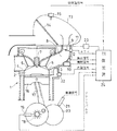
以下、図面を参照して本発明を説明する。図2は、本発明の一実施形態に係る燃料噴射制御装置を組み込んだ内燃機関(エンジン)の要部構成図である。同図において、気筒1の燃焼室2には、吸気ポート3および排気ポート4が開口し、各ポート3,4には吸気弁5および排気弁6がそれぞれ設けられるとともに、点火プラグ7が設けられる。
【0011】
吸気ポート3に通じる吸気通路8には、その開度θTHに応じて吸入空気量を調節するスロットル弁9や燃料噴射弁10、ならびに前記開度θTHを検出するスロットルセンサ11および負圧センサ12が設けられる。吸気通路8の終端にはエアクリーナ13が設けられ、エアクリーナ13内にはエアフィルタ14が設けられ、このエアフィルタ14を通じて吸気通路8へ外気が取り込まれる。さらに、エアクリーナ13内には吸気温センサ15が設けられる。
【0012】
気筒1内にはピストン16が設けられ、このピストン16にコンロッド17を介して連接されたクランク軸18には、クランクの回転角度を検出して所定クランク角毎にクランクパルスを出力する回転角センサ19が対向配置される。さらに、クランク軸18に連結されて回転するギヤ等の回転体20には車速センサ21が対向配置される。気筒1の周りに形成されたウォータジャケットにはエンジン温度を代表する冷却水の温度を検出する水温センサ22が設けられる。なお、前記点火プラグ7には点火コイル23が接続されている。
【0013】
制御装置24はCPUやメモリからなるマイクロコンピュ−タであり、入出力ポート、A/D変換器などのインタフェースを備え、図示しないバッテリから動作電力を得ている。前記各センサの出力は入力ポートを通じて制御装置24に取り込まれる。また、各センサからの入力信号に基づく処理結果に従い、燃料噴射弁10や点火プラグ7に駆動信号が出力される。燃料噴射弁10の駆動信号(噴射信号)は噴射量に応じたパルス幅を有するパルス信号であり、このパルス幅に相当する時間開弁されて吸気通路8に燃料が噴射される。
【0014】
前記噴射信号のパルス幅つまり燃料噴射時間は、負圧センサ12の検出値(吸気通路8の負圧Pb )とエンジン回転数、またはスロットルセンサ11の検出値(スロットル開度θTH)とエンジン回転数に基づいて算出される。本実施形態では、高負荷の時はスロットル開度θTHとエンジン回転数を用い、低負荷時には負圧Pb とエンジン回転数を用いることを基本にしている。そして、負荷の高低はスロットル開度θTHで判断する。しかし、低負荷と判断されるスロットル開度θTHであっても、スロットル開度θTHの変化率DθTHによっては高負荷の時のように、スロットル開度θTHとエンジン回転数を用いて燃料噴射時間を算出する。
【0015】
図3は、燃料噴射の処理を示すフローチャートである。ステップS1ではエンジン回転数Ne を読み込む。エンジン回転数Ne は回転角センサ19から出力されるクランクパルスを計数して求めることができる。ステップS2ではスロットル開度θTHを読み込む。ステップS3ではスロットル開度θTHの変化率DθTHを算出する。スロットル開度θTHの変化率DθTHは、ステップS2で検出されるスロットル開度θTHの、予定時間ΔT前処理時の値θTH1 と今回処理時の値θTH2 とに基づいて次式(f1)で算出できる。変化率DθTH=(θTH2-θTH1)/ΔT…(f1)。
【0016】
ステップS4では、負圧センサ12の検出値つまり吸気管負圧Pb を読み込む。ステップS5では、スロットル開度θTHが、低負荷であるか否かを判断するための第1設定値θref1以上か否かを判断する。この第1設定値θref1はエンジン回転数Ne の関数として記憶されている。ステップS5が否定、つまりスロットル開度θTHが微小ないし全閉ならば、ステップS6で強制移行状態を示すフラグFに「0」をセットし、ステップS7でPBマップを選択する。PBマップはエンジン回転数Ne および負圧Pb の関数としての基本噴射時間TiMを算出するためのマップである。なお、噴射量は噴射時間に対応するので、本明細書では噴射時間で噴射量を代表して説明する。
【0017】
一方、ステップS5が肯定ならば、さらにステップS8においてスロットル開度θTHが、高負荷であるか否かを判断するための第2設定値θref2 (θref2>θref1) 以上か否かを判断する。第2設定値θref2も第1設定値θref1と同様、エンジン回転数Ne の関数として記憶されている。ステップS8が肯定ならば、ステップS9でフラグFに「0」をセットし、ステップS13でTHマップを選択する。THマップはエンジン回転数Ne およびスロットル開度θTHの関数としての基本噴射時間TiMを算出するためのマップである。
【0018】
スロットル開度θTHが第1設定値θref1以上ではあるが、第2設定値θref2に達していない場合は、ステップS10に進んでフラグFが「0」か否か、つまり強制移行状態でないか、強制移行状態であるかを判断する。フラグFが「0」であれば、ステップS11に進み、スロットル開度θTHの変化率DθTHが設定値Dref 以上か否かを判断する。変化率DθTHが設定値Dref 以上であれば、ステップS11は肯定となり、ステップS12に進んで高負荷状態の制御に強制的に移行したことを示すためフラグFに「1」をセットした後、ステップS13に進む。すなわち、スロットル開度変化DθTHが大きい場合は強制的にTHマップ選択に移行する。一方、変化率DθTHが設定値Dref 未満であれば、低負荷とみなしてステップS10からステップS6に移行し、ステップS7に進んでPBマップを選択する。
【0019】
また、第1設定値θref1と第2設定値θref2との間にあって、強制移行状態である場合、すなわち、ステップS11を経てステップS13に進んだ後は、ステップS10は否定となりステップS14,S15の処理に進む。ステップS14,S15では、吸気管負圧Pb がスロットル変化に追いついて、その時のエンジン回転数Ne とスロットル開度θTHに対する定常状態において発生されると推定される値に近付いたかどうかが判断される。定常状態の吸気管負圧Pb はマップとして設定しておくのがよい。
【0020】
図4は、スロットル開度θTHに対応する吸気管負圧設定値Pbsetを、エンジン回転数領域毎に示す図である。ステップS14ではこのマップから、エンジン回転数Ne とスロットル開度θTHとに基づく吸気管負圧設定値Pbsetを検索する。ステップS15では、吸気管負圧Pb と吸気管負圧設定値Pbsetとの差の絶対値が比較値Pbref以下かを判断する。この判断が否定ならばステップS6に進み、強制移行状態を解除してPBマップを選択する。ステップS15が肯定ならば強制移行状態を維持する。
【0021】
ステップS16では、エンジン回転数Ne と負圧Pb とをパラメータとする噴射時間のマップ(PBマップ)またはエンジン回転数Ne とスロットル開度θTHとをパラメータとする噴射時間のマップ(THマップ)により基本噴射時間TiMを算出する。
【0022】
ステップS17では、基本噴射時間TiMに補正係数Aを乗算し、さらに加速補正量TACC と無効噴射時間TiVBを加算して燃料噴射時間Ti を算出する。補正係数Aはエンジン水温や吸気温度等の関数であり、水温センサ22や吸気温センサ15の出力に基づいて予定の計算式を使用して算出するか、水温や吸気温に対応させて係数を記憶させたテーブルを参照して求めることができる。
【0023】
加速補正量TACC はスロットル開度の変化率に応じて算出される。無効噴射時間TiVB は開弁時間のうち燃料の完全な噴射を伴わない時間であり、燃料噴射弁10の形式や構造により決定される。
【0024】
ステップS18では、燃料噴射弁10の駆動信号をそれぞれ燃料噴射時間Tiの間出力する。燃料噴射弁10はこの駆動信号が出力されている間開弁し、吸気通路8に燃料を噴射する。
【0025】
図5はスロットル開度θTHとエンジン回転数Ne をパラメータとするPBマップおよびTHマップの領域を示す図である。同図において、全体として、スロットル開度θTHが大きい所がTHマップの領域であり、スロットル開度θTHが小さい所がPBマップの領域である。
【0026】
THマップ領域およびPBマップ領域の間には、これらのいずれかに固定されない過渡領域があり、この過渡領域では、スロットル開度θTHの変化率DθTHの大小に応じて、変化率DθTHが設定値Dref 未満ではPBマップ領域になり、変化率DθTHが設定値Dref 以上ではTHマップ領域に強制移行される。
【0027】
例えば、過渡領域にあって、変化率DθTHが設定値Dref 未満であれば、スロットル開度θTHが第2設定値θref2を超えたときにTHマップが選択され、その後にスロットル開度θTHが第2設定値θref2を下回ったときにPBマップが選択される(例▲1▼)。また、過渡領域にあって、変化率DθTHが設定値Dref 以上であれば、スロットル開度θTHが第2設定値θref2に達していなくてもTHマップ領域に強制移行される。その後にスロットル開度θTHが第2設定値θref2を超えないまま第1設定値θref1を下回ったときにPBマップが選択される(例▲2▼)。
【0028】
さらに、過渡領域にあって、変化率DθTHが設定値Dref 以上であれば、スロットル開度θTHが第2設定値θref2に達していなくてもTHマップ領域に強制移行される。その後にスロットル開度θTHが第2設定値θref2を超えた後、再び第2設定値θref2を下回ったときは、その時点でPBマップが選択される(例▲3▼)。
【0029】
またさらに、低負荷時であってスロットル開度θTHの変化率DθTHが設定値Dref より大きくてTHマップが選択されている場合、負圧値Pb がスロットル開度θTHに応じて設定された基準負圧値に略一致した時には、PBマップに切替えられる(例▲4▼)。
【0030】
図1は、本実施形態に係る燃料噴射制御装置の要部機能を示すブロック図である。同図において、第1算出部25は、スロットル開度θTHとエンジン回転数Ne とを使用して基本噴射時間を算出する。第2算出部26は、吸気管負圧Pb とエンジン回転数Ne とを使用して基本噴射時間を算出する。負荷検出部27はスロットル開度θTHが上部設定値 (θref2) 以上、もしくは下部設定値 (θref1)以下、またはそれらの間かによって負荷を判別する。選択部28は負荷に応じて、高負荷の場合、つまりスロットル開度がθref2以上のときは第1算出部25を選択し、低負荷の場合、つまりスロットル開度がθref1以上のときは第2算出部26を選択する。
【0031】
変化率算出部29はスロットル開度変化率を算出し、比較部30は、スロットル開度変化率DθTHが基準値Dref より大きい場合に検出出力を切替部31に供給する。切替部31は検出出力に応答して選択部28を第1算出部25が選択されるよう切替える。すなわち、低負荷時であってもスロットル開度の増加率が基準値より大きい場合は、上述の選択基準にかかわらず、第1算出部25が選択されるよう切替部31によって選択部28が強制的に設定される。
【0032】
Pb テーブル33には、スロットル開度θTHに対する吸気管負圧設定値Pbsetがエンジン回転数Ne 毎に記憶されており、第1算出部25が選択されているときに参照され、スロットル開度θTHとエンジン回転数Ne とに基づいて吸気管負圧設定値Pbsetが読み出される。吸気管負圧設定値Pbsetは負圧比較部34で吸気管負圧Pb と比較され、両者が略一致した時に、第2算出部26を選択するよう選択部28が設定される。
【0033】
【発明の効果】
以上の説明から明らかなように、請求項1の発明によれば、低負荷時、つまりスロットル開度が小さい状態でも、スロットル開度の変化が伴えば高負荷時と同様にスロットル開度を使用して噴射量が算出されるので、スロットル操作に対して燃料噴射量の変化が遅れることなく追従できる。そのため、吸気管負圧センサの出力応答遅れがあっても良好なドライバビリティを実現できる。
【0034】
また、請求項2の発明によれば、減速時のドライバビリティが向上する。さらに、請求項3の発明によれば、負圧センサで検出された吸気管負圧値が、スロットル開度に追従して、予め設定された基準負圧値に略一致した時に、吸気管負圧を使用する第2算出部が選択されることによって燃料噴射制御の安定化が図られる。
【図面の簡単な説明】
【図1】 本発明の一実施形態に係る燃料噴射制御装置の要部機能ブロック図である。
【図2】 本発明の燃料噴射制御装置を含む内燃機関の要部構成図である。
【図3】 燃料噴射の処理を示すフローチャートである。
【図4】 定常時の吸気管負圧値とスロットル開度との関係を示す図である。
【図5】 PBマップ領域とTHマップ領域の切替え制御の概要を示す図である。
【符号の説明】
9…スロットル弁、 10…燃料噴射弁、 11…スロットルセンサ、 19…回転角センサ、 24…制御装置、 25…第1算出部、 26…第2算出部、27…負荷検出部、 28…選択部、 29…スロットル開度変化量算出部、33…Pb テーブル[0001]
BACKGROUND OF THE INVENTION
The present invention relates to a fuel injection control device for an internal combustion engine, and more particularly to a fuel injection control device that determines a basic fuel injection amount by a method that varies depending on the degree of load.
[0002]
[Prior art]
Conventionally, as a method for measuring the amount of intake air related to the basic fuel injection amount, a direct method that directly measures using an air flow meter and an indirect method that indirectly measures using a throttle sensor or an intake pipe negative pressure sensor are known. It is done. For example, Japanese Patent Laid-Open No. 4-365934 discloses a fuel injection amount control device that calculates the intake air amount from the throttle opening and the engine speed during transient operation and detects the intake air amount using an air flow meter during steady operation. Is disclosed. In Japanese Patent Publication No. 6-10437, in a device that measures the intake air amount by using either the direct method or the indirect method, the calculated basic fuel injection amount is corrected when switching between both methods is performed. What to do is disclosed.
[0003]
On the other hand, in the fuel injection control of a motorcycle engine, the latter of the direct method and the indirect method is often adopted, and the basic injection amount is calculated from the detected value of the intake pipe negative pressure sensor and the engine speed at low load. When the load is high, the basic injection amount is calculated from the detected value of the throttle sensor and the engine speed. Here, the magnitude of the load is determined by the throttle opening for each engine speed.
[0004]
[Problems to be solved by the invention]
In motorcycles, drivability when the throttle valve is slightly opened from the fully closed state, that is, responsiveness to the operation of opening the throttle valve is importantly related to the overall maneuverability and merchantability. However, the intake pipe negative pressure sensor has poor output response to negative pressure changes. For this reason, during transient operation, the fuel injection amount calculated by the negative pressure and the engine speed is not accurate, resulting in a problem that good drivability cannot be obtained.
[0005]
An object of the present invention is to solve the above-mentioned problems and to provide a fuel injection control device for an internal combustion engine that can improve drivability by improving the followability of a change in fuel injection amount with respect to a throttle operation.
[0006]
[Means for Solving the Problems]
In order to achieve the above object, the present invention has a throttle sensor and an intake passage negative pressure sensor, and calculates the basic fuel injection amount from the throttle opening or negative pressure value detected by these sensors and the engine speed. In the fuel injection control device, the basic injection amount is calculated using the first calculation means for calculating the basic injection amount using the throttle opening and the engine speed, and the negative pressure value and the engine speed. A second calculating means, a means for comparing the rate of increase of the throttle opening with a reference value, a load detecting means, and a selection for selecting the first calculating means at a high load and selecting the second calculating means at a low load. And a switching means for setting the selection means so that the first calculation means is selected regardless of the selection when the increase rate of the throttle opening is larger than the reference value at low load. Point There is a first feature.
[0007]
According to the first feature, even when it is determined that the load is low, if the increase rate of the throttle opening is large, the first calculation means is selected, and the throttle opening and the engine speed are selected. Since the basic fuel injection amount is calculated by this, good drivability can be realized regardless of the output response delay of the intake pipe negative pressure sensor.
[0008]
Further, the present invention provides a fully closed detecting means for detecting that the throttle is substantially fully closed, and the fully closed detecting means when the selecting means is set to select the first calculating means by the switching means. According to the second feature, the second calculating means is selected when the throttle is substantially fully closed. According to the second feature, the intake pipe negative pressure is used in order to enable control of the fuel injection amount in accordance with the sudden deceleration when the throttle turns to a sudden deceleration that is almost fully closed. A reset operation for selecting the second calculation means is performed.
[0009]
Further, according to the present invention, the negative pressure value is set according to the throttle opening when the increase rate of the throttle opening is larger than the reference value and the first calculation means is selected at the time of low load. A third feature is that a return means for switching to the second calculation means when the reference negative pressure value substantially coincides with the reference negative pressure value is provided. According to the third feature, when the intake pipe negative pressure value detected by the negative pressure sensor substantially matches a preset reference negative pressure value following the throttle opening, the second calculating means Selected.
[0010]
DETAILED DESCRIPTION OF THE INVENTION
The present invention will be described below with reference to the drawings. FIG. 2 is a configuration diagram of a main part of an internal combustion engine (engine) incorporating a fuel injection control device according to an embodiment of the present invention. In the figure, an intake port 3 and an exhaust port 4 are opened in the
[0011]
In the intake passage 8 leading to the intake port 3, there are a throttle valve 9 and a
[0012]
A
[0013]
The
[0014]
The pulse width of the injection signal, that is, the fuel injection time is determined by the detection value of the negative pressure sensor 12 (negative pressure Pb of the intake passage 8) and the engine speed, or the detection value of the throttle sensor 11 (throttle opening θTH) and the engine speed. Is calculated based on In this embodiment, the throttle opening θTH and the engine speed are used when the load is high, and the negative pressure Pb and the engine speed are used when the load is low. The load level is determined by the throttle opening θTH. However, even if the throttle opening degree θTH is determined to be low, the fuel injection time is determined by using the throttle opening degree θTH and the engine speed, as in the case of high load, depending on the change rate DθTH of the throttle opening degree θTH. calculate.
[0015]
FIG. 3 is a flowchart showing the fuel injection process. In step S1, the engine speed Ne is read. The engine speed Ne can be obtained by counting the crank pulses output from the
[0016]
In step S4, the detection value of the negative pressure sensor 12, that is, the intake pipe negative pressure Pb is read. In step S5, it is determined whether or not the throttle opening θTH is equal to or greater than a first set value θref1 for determining whether or not the load is low. The first set value θref1 is stored as a function of the engine speed Ne. If step S5 is negative, that is, if the throttle opening .theta.TH is minute or fully closed, "0" is set to the flag F indicating the forced transition state in step S6, and the PB map is selected in step S7. The PB map is a map for calculating the basic injection time TiM as a function of the engine speed Ne and the negative pressure Pb. In addition, since the injection amount corresponds to the injection time, in this specification, the injection amount will be described as a representative of the injection time.
[0017]
On the other hand, if step S5 is affirmative, it is further determined in step S8 whether or not the throttle opening θTH is equal to or greater than a second set value θref2 (θref2> θref1) for determining whether or not the load is high. Similarly to the first set value θref1, the second set value θref2 is also stored as a function of the engine speed Ne. If step S8 is positive, a flag F is set to “0” in step S9, and a TH map is selected in step S13. The TH map is a map for calculating the basic injection time TiM as a function of the engine speed Ne and the throttle opening θTH.
[0018]
If the throttle opening θTH is equal to or greater than the first set value θref1, but has not reached the second set value θref2, the process proceeds to step S10, whether or not the flag F is “0”, that is, the forced transition state is not Determine whether it is in transition state. If the flag F is “0”, the process proceeds to step S11, and it is determined whether or not the rate of change DθTH of the throttle opening θTH is greater than or equal to the set value Dref. If the rate of change DθTH is greater than or equal to the set value Dref, step S11 becomes affirmative, and after proceeding to step S12, the flag F is set to “1” to indicate that the control has been forcibly shifted to the high load state, and then step Proceed to S13. That is, when the throttle opening change DθTH is large, the process forcibly shifts to TH map selection. On the other hand, if the rate of change DθTH is less than the set value Dref, it is regarded as a low load, the process proceeds from step S10 to step S6, and the process proceeds to step S7 to select a PB map.
[0019]
In addition, when it is between the first set value θref1 and the second set value θref2 and is in the forced transition state, that is, after proceeding to step S13 via step S11, step S10 is negative and the processing of steps S14 and S15 is performed. Proceed to In steps S14 and S15, it is determined whether or not the intake pipe negative pressure Pb has caught up with the throttle change and has approached a value estimated to be generated in a steady state with respect to the engine speed Ne and the throttle opening θTH at that time. The intake pipe negative pressure Pb in the steady state is preferably set as a map.
[0020]
FIG. 4 is a diagram showing the intake pipe negative pressure set value Pbset corresponding to the throttle opening θTH for each engine speed region. In step S14, an intake pipe negative pressure set value Pbset based on the engine speed Ne and the throttle opening θTH is searched from this map. In step S15, it is determined whether the absolute value of the difference between the intake pipe negative pressure Pb and the intake pipe negative pressure set value Pbset is equal to or smaller than the comparison value Pbref. If this determination is negative, the process proceeds to step S6 to cancel the forced transition state and select the PB map. If step S15 is positive, the forced transition state is maintained.
[0021]
In step S16, the injection time map (PB map) using the engine speed Ne and the negative pressure Pb as parameters or the injection time map (TH map) using the engine speed Ne and the throttle opening θTH as parameters is used as a basis. An injection time TiM is calculated.
[0022]
In step S17, the fuel injection time Ti is calculated by multiplying the basic injection time TiM by the correction coefficient A and further adding the acceleration correction amount TACC and the invalid injection time TiVB. The correction coefficient A is a function of the engine water temperature, the intake air temperature, etc., and is calculated using a predetermined calculation formula based on the output of the
[0023]
The acceleration correction amount TACC is calculated according to the change rate of the throttle opening. The invalid injection time TiVB is the time during which the fuel is not completely injected during the valve opening time, and is determined by the type and structure of the
[0024]
In step S18, a drive signal for the
[0025]
FIG. 5 is a diagram showing regions of the PB map and TH map using the throttle opening θTH and the engine speed Ne as parameters. In the figure, as a whole, a place where the throttle opening degree θTH is large is a region of the TH map, and a place where the throttle opening degree θTH is small is a region of the PB map.
[0026]
There is a transition region that is not fixed to any of these between the TH map region and the PB map region. In this transition region, the change rate DθTH is set to the set value Dref according to the change rate DθTH of the throttle opening θTH. If the change rate DθTH is greater than or equal to the set value Dref, it is forcibly transferred to the TH map region.
[0027]
For example, if the change rate DθTH is less than the set value Dref in the transient region, the TH map is selected when the throttle opening θTH exceeds the second set value θref2, and then the throttle opening θTH is set to the second value. A PB map is selected when the value falls below the set value θref2 (example (1)). In the transition region, if the rate of change DθTH is equal to or greater than the set value Dref, the throttle map is forcibly shifted to the TH map region even if the throttle opening θTH has not reached the second set value θref2. Thereafter, the PB map is selected when the throttle opening θTH falls below the first set value θref1 without exceeding the second set value θref2 (example (2)).
[0028]
Further, if the rate of change DθTH is greater than or equal to the set value Dref in the transient region, the throttle map is forcibly shifted to the TH map region even if the throttle opening θTH has not reached the second set value θref2. After that, when the throttle opening θTH exceeds the second set value θref2 and then falls below the second set value θref2, the PB map is selected at that time (example (3)).
[0029]
Furthermore, when the load is low and the change rate DθTH of the throttle opening θTH is larger than the set value Dref and the TH map is selected, the negative pressure value Pb is set to the reference negative value set according to the throttle opening θTH. When the pressure value substantially matches, the PB map is switched (example (4)).
[0030]
FIG. 1 is a block diagram showing the main functions of the fuel injection control apparatus according to this embodiment. In the figure, the
[0031]
The change
[0032]
In the Pb table 33, the intake pipe negative pressure set value Pbset with respect to the throttle opening θTH is stored for each engine speed Ne, and is referred to when the
[0033]
【The invention's effect】
As is apparent from the above description, according to the invention of
[0034]
Further, according to the invention of
[Brief description of the drawings]
FIG. 1 is a functional block diagram of a main part of a fuel injection control device according to an embodiment of the present invention.
FIG. 2 is a configuration diagram of a main part of an internal combustion engine including a fuel injection control device of the present invention.
FIG. 3 is a flowchart showing a fuel injection process.
FIG. 4 is a graph showing a relationship between a steady-state intake pipe negative pressure value and a throttle opening.
FIG. 5 is a diagram showing an outline of switching control between a PB map area and a TH map area;
[Explanation of symbols]
DESCRIPTION OF SYMBOLS 9 ... Throttle valve, 10 ... Fuel injection valve, 11 ... Throttle sensor, 19 ... Rotation angle sensor, 24 ... Control device, 25 ... 1st calculation part, 26 ... 2nd calculation part, 27 ... Load detection part, 28 ... Selection 29: Throttle opening change amount calculation unit 33: Pb table
Claims (2)
スロットル開度(θTH)の増加率(DθTH)を基準値(Dref)と比較する比較手段(30)と、
スロットル開度(θTH)が、下部設定値(θref1)未満のPBマップ領域であるか、上部設定値(θref2)以上のTHマップ領域であるか、PBマップ領域とTHマップ領域との間にある過渡領域であるかを検出する負荷検出手段(27)と、
スロットル開度(θTH)が、前記上部設定値(θref2)以上のTHマップ領域にあるときに前記第1算出手段(25)を選択し、スロットル開度(θTH)が前記下部設定値(θref1)未満のPBマップ領域であるときに前記第2算出手段(26)を選択するとともに、前記過渡領域では、前記スロットル開度増加率(DθTH)が基準値(Dref)以上のときは前記第1算出手段(25)を選択し、前記スロットル開度増加率(θTH)が基準値(Dref)未満のときは前記第2算出手段(26)を選択する選択手段(28)とを具備し、
前記選択手段(28)が、
過渡領域で前記第2算出手段(26)が選択されている状態で、スロットル開度(θTH)が上部設定値(θref2)以上のTHマップ領域に変化した場合に、前記第2算出手段(26)に代えて前記第1算出手段(25)を選択し、その後、スロットル開度(θTH)が上部設定値(θref2)未満の過渡領域に変化した時に、前記第1算出手段(25)に代えて前記第2算出手段(26)を選択する第1パターンと、
過渡領域で前記第2算出手段(26)が選択されている状態で、スロットル開度増加率(DθTH)が基準値(Dref)以上となった場合に、前記第2算出手段(26)に代えて前記第1算出手段(25)を選択し、その後、スロットル開度(θTH)が上部設定値(θref2)以上のTHマップ領域に変化しないまま、下部設定値(θref1)未満のPBマップ領域に変化した時に、前記第1算出手段(25)に代えて前記第2算出手段(26)を選択する第2パターンと、
過渡領域で前記第2算出手段(26)が選択されている状態で、スロットル開度増加率(DθTH)が基準値(Dref)以上となった場合に、前記第2算出手段(26)に代えて前記第1算出手段(25)を選択し、その後、スロットル開度(θTH)が上部設定値(θref2)以上のTHマップ領域に変化した時は前記第1算出手段の選択を維持し、さらにその後、スロットル開度(θTH)が上部設定値(θref2)未満の過渡領域に変化した時は、前記第1算出手段(25)に代えて前記第2算出手段(26)を選択する第3パターンと、
過渡領域で前記第1算出手段(25)が選択されている場合に、吸気通路負圧値が、スロットル開度(θTH)に応じて設定される基準負圧値(Pbset)に略一致した時に前記第1算出手段(25)に代えて前記第2算出手段(26)を選択する第4パターンとからなる選択パターンを含んでいることを特徴とする燃料噴射制御装置。 A throttle sensor (11 ) for detecting the throttle opening (θTH), an intake passage negative pressure sensor (12) for detecting the intake passage negative pressure value (Pb), and an engine speed sensor for detecting the engine speed (Ne) (19), first calculation means (25) for calculating a basic injection amount by searching a TH map based on the throttle opening (θTH) and the engine speed (Ne), the intake passage negative pressure value (Pb), and the engine In a fuel injection control device having a second calculation means (26) for searching a PB map based on a rotational speed (Ne) and calculating a basic injection amount ,
A comparison means (30) for comparing an increase rate (DθTH ) of the throttle opening (θTH) with a reference value (Dref) ;
The throttle opening (θTH) is a PB map region less than the lower set value (θref1), a TH map region greater than the upper set value (θref2), or between the PB map region and the TH map region Load detection means (27) for detecting whether the region is a transient region ;
The first calculating means (25) is selected when the throttle opening (θTH) is in the TH map region equal to or higher than the upper set value (θref2) , and the throttle opening (θTH) is set to the lower set value (θref1). The second calculation means (26) is selected when the PB map area is less than the first area, and the first calculation is performed when the throttle opening increase rate (DθTH) is equal to or greater than a reference value (Dref) in the transient area. Selecting means (25), and selecting means (28) for selecting the second calculation means (26) when the throttle opening increase rate (θTH) is less than a reference value (Dref) ,
The selection means (28)
When the throttle opening (θTH) is changed to a TH map region equal to or higher than the upper set value (θref2) in a state where the second calculation unit (26) is selected in the transient region, the second calculation unit (26 ) Is selected instead of the first calculation means (25), and then the first calculation means (25) is replaced when the throttle opening (θTH) changes to a transient region less than the upper set value (θref2). A first pattern for selecting the second calculation means (26),
When the second calculation means (26) is selected in the transient region and the throttle opening increase rate (DθTH) is equal to or higher than the reference value (Dref), the second calculation means (26) is used instead. The first calculating means (25) is selected, and then the throttle opening (θTH) does not change to a TH map region greater than or equal to the upper set value (θref2), and the PB map region is less than the lower set value (θref1). A second pattern for selecting the second calculation means (26) instead of the first calculation means (25) when changed,
When the second calculation means (26) is selected in the transient region and the throttle opening increase rate (DθTH) is equal to or higher than the reference value (Dref), the second calculation means (26) is used instead. The first calculation means (25) is selected, and then the selection of the first calculation means is maintained when the throttle opening (θTH) is changed to a TH map region equal to or higher than the upper set value (θref2). Thereafter, when the throttle opening (θTH) changes to a transient region less than the upper set value (θref2), a third pattern for selecting the second calculation means (26) instead of the first calculation means (25). When,
When the first calculation means (25) is selected in the transient region, when the intake passage negative pressure value substantially matches the reference negative pressure value (Pbset) set according to the throttle opening (θTH) A fuel injection control apparatus comprising a selection pattern comprising a fourth pattern for selecting the second calculation means (26) instead of the first calculation means (25) .
前記選択手段(28)が第1算出手段(25)を選択するように設定されている時に、前記全閉検出手段によりスロットルの略全閉が検出された場合、前記第2算出手段(26)を選択することを特徴とする請求項1記載の燃料噴射制御装置。A fully-closed detecting means for detecting that the throttle is substantially fully closed ;
If the selecting means (28) when being set to select the first calculation means (25), throttle substantially fully closed is detected by the full-closing detecting means, said second calculating means (26) The fuel injection control device according to claim 1, wherein the fuel injection control device is selected.
Priority Applications (4)
| Application Number | Priority Date | Filing Date | Title |
|---|---|---|---|
| JP2001124480A JP4354659B2 (en) | 2000-06-29 | 2001-04-23 | Fuel injection control device |
| ES200101453A ES2196960B1 (en) | 2000-06-29 | 2001-06-22 | FUEL INJECTION CONTROL DEVICE. |
| IT2001TO000612A ITTO20010612A1 (en) | 2000-06-29 | 2001-06-26 | CONTROL EQUIPMENT FOR FUEL INJECTION. |
| US09/893,552 US6467459B2 (en) | 2000-04-23 | 2001-06-29 | Fuel injection control apparatus |
Applications Claiming Priority (3)
| Application Number | Priority Date | Filing Date | Title |
|---|---|---|---|
| JP2000-196359 | 2000-06-29 | ||
| JP2000196359 | 2000-06-29 | ||
| JP2001124480A JP4354659B2 (en) | 2000-06-29 | 2001-04-23 | Fuel injection control device |
Publications (2)
| Publication Number | Publication Date |
|---|---|
| JP2002081337A JP2002081337A (en) | 2002-03-22 |
| JP4354659B2 true JP4354659B2 (en) | 2009-10-28 |
Family
ID=26594983
Family Applications (1)
| Application Number | Title | Priority Date | Filing Date |
|---|---|---|---|
| JP2001124480A Expired - Fee Related JP4354659B2 (en) | 2000-04-23 | 2001-04-23 | Fuel injection control device |
Country Status (4)
| Country | Link |
|---|---|
| US (1) | US6467459B2 (en) |
| JP (1) | JP4354659B2 (en) |
| ES (1) | ES2196960B1 (en) |
| IT (1) | ITTO20010612A1 (en) |
Families Citing this family (9)
| Publication number | Priority date | Publication date | Assignee | Title |
|---|---|---|---|---|
| US6766819B2 (en) | 2001-08-21 | 2004-07-27 | Delphi Technologies, Inc. | Apparatus and method for adjusting and sealing a solenoid valve |
| JP4203983B2 (en) * | 2002-03-19 | 2009-01-07 | ヤマハ発動機株式会社 | Intake negative pressure detection device for internal combustion engine |
| JP4604818B2 (en) * | 2005-04-28 | 2011-01-05 | 国産電機株式会社 | Engine fuel injection control device |
| JP2010261385A (en) * | 2009-05-08 | 2010-11-18 | Suzuki Motor Corp | Electronic control throttle valve control apparatus |
| JP5264628B2 (en) * | 2009-06-17 | 2013-08-14 | 三菱電機株式会社 | Control device for internal combustion engine |
| JP5197548B2 (en) * | 2009-11-05 | 2013-05-15 | 本田技研工業株式会社 | Fuel injection control device for internal combustion engine |
| JP6060006B2 (en) * | 2013-02-22 | 2017-01-11 | 本田技研工業株式会社 | Fuel injection control device |
| CN105986917A (en) * | 2016-06-30 | 2016-10-05 | 深圳市元征科技股份有限公司 | Control method and device for oil injection amount of engine |
| CN112112739B (en) * | 2020-08-21 | 2021-08-24 | 中联重科股份有限公司 | Vehicle engine rotating speed calibration method, calibration system, calibration device and equipment |
Family Cites Families (8)
| Publication number | Priority date | Publication date | Assignee | Title |
|---|---|---|---|---|
| JPS5696132A (en) * | 1979-12-28 | 1981-08-04 | Honda Motor Co Ltd | Engine controller |
| JPS5751921A (en) * | 1980-09-16 | 1982-03-27 | Honda Motor Co Ltd | Fuel controller for internal combustion engine |
| JPS58158345A (en) * | 1982-03-15 | 1983-09-20 | Nippon Denso Co Ltd | Control method for engine |
| JPH01267338A (en) * | 1988-04-19 | 1989-10-25 | Mitsubishi Electric Corp | Adaptive air-fuel ratio control device for internal combustion engine |
| US5268842A (en) * | 1990-12-03 | 1993-12-07 | Cummins Engine Company, Inc. | Electronic control of engine fuel injection based on engine duty cycle |
| JPH04303146A (en) * | 1991-03-30 | 1992-10-27 | Mazda Motor Corp | Fuel controlling device for engine |
| JPH04365943A (en) | 1991-06-11 | 1992-12-17 | Toyota Motor Corp | Fuel injection amount control device for internal combustion engine |
| JP2652109B2 (en) | 1992-06-25 | 1997-09-10 | ワイケイケイアーキテクチュラルプロダクツ株式会社 | Roofs such as terraces and carports |
-
2001
- 2001-04-23 JP JP2001124480A patent/JP4354659B2/en not_active Expired - Fee Related
- 2001-06-22 ES ES200101453A patent/ES2196960B1/en not_active Expired - Fee Related
- 2001-06-26 IT IT2001TO000612A patent/ITTO20010612A1/en unknown
- 2001-06-29 US US09/893,552 patent/US6467459B2/en not_active Expired - Lifetime
Also Published As
| Publication number | Publication date |
|---|---|
| ITTO20010612A1 (en) | 2002-12-26 |
| ES2196960A1 (en) | 2003-12-16 |
| ES2196960B1 (en) | 2005-02-01 |
| US6467459B2 (en) | 2002-10-22 |
| JP2002081337A (en) | 2002-03-22 |
| US20020007822A1 (en) | 2002-01-24 |
Similar Documents
| Publication | Publication Date | Title |
|---|---|---|
| JP4354659B2 (en) | Fuel injection control device | |
| KR940001682Y1 (en) | Fuel injection device | |
| US5664544A (en) | Apparatus and method for control of an internal combustion engine | |
| JP3544197B2 (en) | Electronic control unit for internal combustion engine | |
| JP2009007940A (en) | Cylinder-charged air quantity calculating apparatus for internal combustion engine | |
| JP2591203B2 (en) | Air-fuel ratio control device for internal combustion engine | |
| JPH0465227B2 (en) | ||
| JP3938670B2 (en) | Fuel injection control device | |
| JP3591001B2 (en) | Control device for internal combustion engine | |
| JP2006233769A (en) | Acceleration controller for internal combustion engine | |
| JPH0316498B2 (en) | ||
| JPH0573907B2 (en) | ||
| JP4024631B2 (en) | Fuel injection control device for internal combustion engine | |
| JPH09317568A (en) | Abnormality detecting device for diesel engine | |
| JP4001319B2 (en) | Fuel injection control device | |
| JP4194030B2 (en) | Engine fuel injection control device | |
| JP4010778B2 (en) | Fuel injection control device | |
| JP4248129B2 (en) | Fuel injection control device for internal combustion engine | |
| JPS6245953A (en) | Fuel supply controller for internal combustion engine | |
| JP3966463B2 (en) | Fuel injection device for internal combustion engine | |
| JPH0565838A (en) | Fuel supply device for internal combustion engine | |
| JPH10122057A (en) | Egr controller for engine | |
| JP3606066B2 (en) | Ignition timing control device for internal combustion engine | |
| JPH08189368A (en) | Deceleration control device for engine | |
| JP2004100619A (en) | Fuel injection control device of internal combustion engine |
Legal Events
| Date | Code | Title | Description |
|---|---|---|---|
| A621 | Written request for application examination |
Free format text: JAPANESE INTERMEDIATE CODE: A621 Effective date: 20041203 |
|
| A977 | Report on retrieval |
Free format text: JAPANESE INTERMEDIATE CODE: A971007 Effective date: 20061130 |
|
| A131 | Notification of reasons for refusal |
Free format text: JAPANESE INTERMEDIATE CODE: A131 Effective date: 20070307 |
|
| A02 | Decision of refusal |
Free format text: JAPANESE INTERMEDIATE CODE: A02 Effective date: 20070523 |
|
| A521 | Request for written amendment filed |
Free format text: JAPANESE INTERMEDIATE CODE: A523 Effective date: 20070618 |
|
| A911 | Transfer to examiner for re-examination before appeal (zenchi) |
Free format text: JAPANESE INTERMEDIATE CODE: A911 Effective date: 20070724 |
|
| A912 | Re-examination (zenchi) completed and case transferred to appeal board |
Free format text: JAPANESE INTERMEDIATE CODE: A912 Effective date: 20070817 |
|
| A521 | Request for written amendment filed |
Free format text: JAPANESE INTERMEDIATE CODE: A523 Effective date: 20090701 |
|
| A01 | Written decision to grant a patent or to grant a registration (utility model) |
Free format text: JAPANESE INTERMEDIATE CODE: A01 |
|
| A61 | First payment of annual fees (during grant procedure) |
Free format text: JAPANESE INTERMEDIATE CODE: A61 Effective date: 20090730 |
|
| R150 | Certificate of patent or registration of utility model |
Free format text: JAPANESE INTERMEDIATE CODE: R150 |
|
| FPAY | Renewal fee payment (event date is renewal date of database) |
Free format text: PAYMENT UNTIL: 20120807 Year of fee payment: 3 |
|
| FPAY | Renewal fee payment (event date is renewal date of database) |
Free format text: PAYMENT UNTIL: 20120807 Year of fee payment: 3 |
|
| FPAY | Renewal fee payment (event date is renewal date of database) |
Free format text: PAYMENT UNTIL: 20130807 Year of fee payment: 4 |
|
| FPAY | Renewal fee payment (event date is renewal date of database) |
Free format text: PAYMENT UNTIL: 20140807 Year of fee payment: 5 |
|
| LAPS | Cancellation because of no payment of annual fees |