JP4352223B2 - Ignition system for capacitor discharge internal combustion engine - Google Patents
Ignition system for capacitor discharge internal combustion engine Download PDFInfo
- Publication number
- JP4352223B2 JP4352223B2 JP2003281130A JP2003281130A JP4352223B2 JP 4352223 B2 JP4352223 B2 JP 4352223B2 JP 2003281130 A JP2003281130 A JP 2003281130A JP 2003281130 A JP2003281130 A JP 2003281130A JP 4352223 B2 JP4352223 B2 JP 4352223B2
- Authority
- JP
- Japan
- Prior art keywords
- ignition
- capacitor
- coil
- voltage
- bias
- Prior art date
- Legal status (The legal status is an assumption and is not a legal conclusion. Google has not performed a legal analysis and makes no representation as to the accuracy of the status listed.)
- Expired - Fee Related
Links
Images

Description
本発明は、内燃機関の燃焼状態を判定するために、点火プラグの電極間を通してイオン電流を流す手段と該イオン電流を検出する手段とを備えたコンデンサ放電式内燃機関用点火装置に関するものである。 The present invention relates to an ignition device for a capacitor discharge type internal combustion engine having means for flowing an ionic current through electrodes of a spark plug and means for detecting the ionic current in order to determine the combustion state of the internal combustion engine. .
近年、内燃機関の排気ガスの浄化や、燃費の向上などを図るために、機関の点火時期の制御を高精度に行うことが必要とされるようになっており、それに伴って、機関の点火時の燃焼状態に関する情報を制御条件として用いることが行われるようになっている。 In recent years, in order to purify exhaust gas from internal combustion engines and improve fuel efficiency, it has become necessary to control the ignition timing of the engine with high precision. Information regarding the combustion state at the time is used as a control condition.
火花点火式の内燃機関においては、点火プラグで放電が生じた際にその周囲の混合気の温度が上昇して燃焼が開始されると火炎核が形成され、その周囲に火炎が伝搬していく。このとき点火プラグの電極付近にイオンが発生する。このイオンの発生量は、機関の燃焼状態により微妙に変化し、イオンの発生量により点火プラグの電極間の抵抗値が変化する。従って、点火直後の点火プラグの電極間の抵抗値を検出すると、空燃比の状態や、機関の点火タイミングの適否、あるいは機関の失火状態などを検出することができる。点火プラグの電極間の抵抗値は、点火プラグに点火用の高電圧を印加した後、外部から点火プラグに電圧を印加したときに点火プラグを通して流れるイオン電流を検出することにより求めることができる。 In a spark ignition type internal combustion engine, when a discharge is generated in a spark plug, a flame nucleus is formed when the temperature of the surrounding air-fuel mixture rises and combustion starts, and the flame propagates around it. . At this time, ions are generated near the electrode of the spark plug. The amount of ions generated varies slightly depending on the combustion state of the engine, and the resistance value between the electrodes of the spark plug varies depending on the amount of ions generated. Therefore, by detecting the resistance value between the electrodes of the spark plug immediately after ignition, it is possible to detect the air-fuel ratio state, the suitability of the engine ignition timing, the engine misfire state, and the like. The resistance value between the electrodes of the spark plug can be obtained by detecting an ionic current flowing through the spark plug when a voltage is applied to the spark plug from the outside after applying a high voltage for ignition to the spark plug.
そこで、特許文献1に示されているように、イオン電流を検出する手段を備えたコンデンサ放電式の点火装置が提案されている。特許文献1に示されたコンデンサ放電式の点火装置においては、点火コイルの二次コイルの非接地側端子と接地間にダイオードとバイアス用コンデンサとイオン電流検出用抵抗器との直列回路を接続して、機関の点火時に点火プラグと点火コイルの二次コイルとを通して流れる火花放電電流により上記バイアス用コンデンサを充電し、点火開始後、火花放電時間が経過した後に上記ダイオードを短絡してバイアス用コンデンサに蓄積された電荷を点火コイルの二次コイルと点火プラグとイオン電流検出用抵抗器とを通して放電させることにより、イオン電流を流すようにしている。イオン電流は、イオン電流検出用抵抗器の両端に生じる電圧降下(検出電圧)から求めることができる。
特許文献1に示されたように、イオン電流を流す電圧源として用いるバイアス用コンデンサを火花放電電流により充電するようにした場合には、以下に示すような問題が生じる。 As shown in Patent Document 1, when a bias capacitor used as a voltage source for passing an ionic current is charged with a spark discharge current, the following problems occur.
(a)内燃機関の点火時に点火プラグで火花放電が起こらなかったとき(点火プラグの電極間の絶縁を破壊することができなかったとき)に、バイアス用コンデンサを充電することができないため、点火プラグの電極間に電圧を印加することができない。 (A) When no spark discharge occurs in the spark plug during ignition of the internal combustion engine (when the insulation between the electrodes of the spark plug cannot be broken), the bias capacitor cannot be charged. A voltage cannot be applied between the plug electrodes.
(b)バイアス用コンデンサは、イオン電流の測定中放電を続けるため、流れたイオン電流の量に応じて該コンデンサの両端の電圧が低下する。そのため、点火プラグの電極間の抵抗値が一定であっても、イオン電流検出用抵抗器の両端に生じる検出電圧が低下していき、イオン電流の検出を正確に行うことが難しくなる。バイアス用コンデンサの静電容量を大きくして、該コンデンサを十分に充電しておけば、イオン電流測定中に生じる検出電圧の低下を少なくして、イオン電流の検出をより正確に行うことができるが、特許文献1に示された点火装置のように、火花放電電流によりバイアス用コンデンサを充電するようにした場合には、最大でも流れた火花放電電流分しかコンデンサを充電することができないため、バイアス用コンデンサの容量を大きくしても、検出電圧の低下を抑制する効果を得ることはできない。 (B) Since the bias capacitor continues to discharge during the measurement of the ionic current, the voltage across the capacitor decreases according to the amount of the ionic current that flows. Therefore, even if the resistance value between the electrodes of the spark plug is constant, the detection voltage generated at both ends of the ion current detection resistor is lowered, and it is difficult to accurately detect the ion current. If the capacitance of the bias capacitor is increased and the capacitor is sufficiently charged, the decrease in detection voltage that occurs during ion current measurement can be reduced, and ion current can be detected more accurately. However, as in the ignition device shown in Patent Document 1, when the bias capacitor is charged with the spark discharge current, the capacitor can be charged only for the spark discharge current that has flown at most. Even if the capacitance of the bias capacitor is increased, it is not possible to obtain the effect of suppressing the decrease in the detection voltage.
(c)内燃機関用点火装置において、点火コイルの二次コイルの両端を非接地として、機関の第1気筒及び第2気筒にそれぞれ取り付けられた第1及び第2の点火プラグを、該二次コイルの一端と接地間及び他端と接地間にそれぞれ接続する構成をとる場合(同時発火タイプの点火コイルを用いる場合)には、機関の点火時に火花放電電流が点火コイルの二次コイルと2つの点火プラグとにより構成される閉回路を流れるため、火花放電電流によりバイアス用コンデンサを充電する構成をとることができない。 (C) In the ignition device for an internal combustion engine, the first and second ignition plugs attached to the first cylinder and the second cylinder of the engine, respectively, with both ends of the secondary coil of the ignition coil being ungrounded, In the case of connecting the coil between one end and the ground and between the other end and the ground (when a simultaneous ignition type ignition coil is used), the spark discharge current is generated between the secondary coil of the ignition coil and the secondary coil when the engine is ignited. Since it flows through a closed circuit composed of two spark plugs, it is not possible to charge the bias capacitor with a spark discharge current.
本発明の目的は、機関の点火時に火花放電が起こらなかった場合でも点火プラグの電極間にイオン電流検出用の電圧を印加することができるようにしたコンデンサ放電式内燃機関用点火装置を提供することにある。 SUMMARY OF THE INVENTION An object of the present invention is to provide an ignition device for a capacitor discharge internal combustion engine in which an ion current detection voltage can be applied between the electrodes of a spark plug even when spark discharge does not occur during engine ignition. There is.
本発明の他の目的は、バイアス用コンデンサの容量を大きくして該コンデンサに十分なエネルギを蓄積し、イオン電流測定中におけるバイアスコンデンサの両端の電圧の低下を抑制して、イオン電流の検出精度を高めることができるようにしたコンデンサ放電式内燃機関用点火装置を提供することにある。 Another object of the present invention is to increase the capacity of the bias capacitor to accumulate sufficient energy in the capacitor, and to suppress the voltage drop across the bias capacitor during ion current measurement, thereby detecting the ion current detection accuracy. It is an object of the present invention to provide an ignition device for a capacitor discharge type internal combustion engine that can improve the engine.
本発明の更に他の目的は、同時発火タイプの点火コイルを用いる場合でも、バイアス用コンデンサを充電して、該コンデンサから点火プラグの電極間にイオン電流検出用の電圧を印加することができるようにしたコンデンサ放電式内燃機関用点火装置を提供することにある。 Still another object of the present invention is to charge a bias capacitor and apply an ion current detection voltage between the capacitor and the electrode of the spark plug even when a simultaneous ignition type ignition coil is used. An object of the present invention is to provide a capacitor discharge type internal combustion engine ignition device.
本発明は、二次コイルに少なくとも1つの点火プラグが負荷される点火コイルと、点火コンデンサ充電用の直流電圧を出力する点火電源部と、前記点火コイルの一次側に設けられて前記点火電源部から得られる電圧により一方の極性に充電される点火コンデンサと、点火信号が与えられたときに導通して点火コンデンサの電荷を点火コイルの一次コイルを通して放電させる放電用スイッチと、内燃機関の点火時期に放電用スイッチに点火信号を与える手段を有する制御部とを備えたコンデンサ放電式内燃機関用点火装置を対象とする。 The present invention provides an ignition coil in which at least one ignition plug is loaded on a secondary coil, an ignition power supply unit that outputs a DC voltage for charging an ignition capacitor, and the ignition power supply unit provided on the primary side of the ignition coil. An ignition capacitor that is charged to one polarity by a voltage obtained from, a discharge switch that conducts when the ignition signal is applied and discharges the charge of the ignition capacitor through the primary coil of the ignition coil, and ignition timing of the internal combustion engine And a control unit having a means for giving an ignition signal to the discharge switch.
本発明においては、点火電源部の出力により逆流阻止用ダイオードを通して充電されるバイアス用コンデンサと、このバイアス用コンデンサの両端に得られるバイアス電圧を点火プラグの両端に印加するバイアス電圧印加回路と、バイアス電圧により点火プラグの電極間を通して流れるイオン電流を検出するイオン電流検出回路とを設けた。 In the present invention, a bias capacitor charged through the backflow prevention diode by the output of the ignition power supply unit, a bias voltage application circuit for applying a bias voltage obtained at both ends of the bias capacitor to both ends of the spark plug, and a bias An ion current detection circuit for detecting an ion current flowing between the electrodes of the spark plug by a voltage is provided.
また上記制御部は、少なくとも内燃機関の点火時期からイオン電流の検出が完了する時期までの間点火電源部が点火コンデンサ充電用直流電圧を出力するのを禁止するように点火電源部を制御する点火電源部制御手段を備えている。Further, the control unit controls the ignition power source unit so as to prohibit the ignition power source unit from outputting the DC voltage for charging the ignition capacitor at least from the ignition timing of the internal combustion engine to the time when the detection of the ionic current is completed. Power supply unit control means is provided.
上記のように、点火電源部の出力によりバイアス用コンデンサを充電すると、機関の点火時に点火プラグで火花放電が発生しなかった場合でもバイアス用コンデンサを充電して、点火プラグの電極間にイオン電流検出用の電圧を印加することができる。 As described above, when the bias capacitor is charged by the output of the ignition power supply unit, even if no spark discharge is generated in the spark plug at the time of ignition of the engine, the bias capacitor is charged and the ionic current is generated between the electrodes of the spark plug. A voltage for detection can be applied.
また上記のように構成するとバイアス用コンデンサの静電容量を大きくしても該コンデンサを十分に充電することができるため、イオン電流の測定中に点火プラグに印加される電圧が低下するのを抑制することができ、イオン電流の検出を従来より高精度で行わせることができる。 In addition, with the above configuration, even if the capacitance of the bias capacitor is increased, the capacitor can be sufficiently charged, so that the voltage applied to the spark plug during the measurement of the ionic current is prevented from decreasing. Therefore, the detection of the ion current can be performed with higher accuracy than before.
更に、上記のように構成すると、点火コイルとして、二次コイルの一端及び他端がそれぞれ第1の点火プラグ及び第2の点火プラグの非接地側端子に接続される同時発火式の点火コイルが用いられる場合でも、バイアス用コンデンサを充電することができるため、同時発火タイプの点火コイルが用いられるコンデンサ放電式内燃機関用点火装置にもイオン電流を検出する機能を持たせることができる。 Further, when configured as described above, the ignition coil is a simultaneous ignition type ignition coil in which one end and the other end of the secondary coil are connected to the non-ground side terminals of the first ignition plug and the second ignition plug, respectively. Even when used, since the bias capacitor can be charged, the capacitor discharge type internal combustion engine ignition device using the simultaneous ignition type ignition coil can be provided with a function of detecting ion current.
イオン電流の検出中に点火コンデンサの充電が開始されると、点火コンデンサの両端の電圧が逆流阻止用ダイオードを通して点火プラグに印加されるため、点火コンデンサの両端の電圧がバイアス用コンデンサの両端の電圧よりも高くなると、イオン電流は点火コンデンサ側から流れるようになる。このイオン電流はイオン電流検出回路を通らずに流れるため、イオン電流の検出を行うことができなくなる。When charging of the ignition capacitor is started during the detection of the ionic current, the voltage across the ignition capacitor is applied to the spark plug through the backflow prevention diode, so the voltage across the ignition capacitor is the voltage across the bias capacitor. Becomes higher, the ion current flows from the ignition capacitor side. Since the ion current flows without passing through the ion current detection circuit, the ion current cannot be detected.
上記のように、制御部に点火電源部制御手段を設けて、イオン電流の検出が完了するまでの間点火電源部が点火コンデンサ充電用直流電圧を出力するのを禁止するようにしておくと、イオン電流の検出を行っている間点火コンデンサが充電されるのを防ぐことができるため、点火コンデンサ側からイオン電流が流れてイオン電流の検出を行うことができなくなる事態が生じるのを防ぐことができる。As described above, the control unit is provided with an ignition power source control unit so that the ignition power source unit is prohibited from outputting the ignition capacitor charging DC voltage until the detection of the ionic current is completed. Since it is possible to prevent the ignition capacitor from being charged while the ion current is being detected, it is possible to prevent a situation where the ion current flows from the ignition capacitor side and the ion current cannot be detected. it can.
点火制御部制御手段が点火制御部からの電圧出力の禁止を開始するタイミングは、点火コンデンサの充電が完了するタイミング(点火コンデンサの両端の電圧が予め定めた設定値に達するタイミング)まで進めることができる。The timing at which the ignition control unit control means starts prohibiting the output of the voltage from the ignition control unit can be advanced to the timing at which charging of the ignition capacitor is completed (the timing at which the voltage at both ends of the ignition capacitor reaches a predetermined set value). it can.
コンデンサ放電式の内燃機関用点火装置において、点火コイルとして同時発火タイプのものを用いる場合には、点火コイルの一次コイルの一端が点火電源部の負極性側出力端子とともに接地され、二次コイルの一端及び他端にそれぞれ第1の点火プラグの非接地側端子及び第2の点火プラグの非接地側端子が接続される。 In the capacitor discharge type internal combustion engine ignition device, when a simultaneous ignition type is used as the ignition coil, one end of the primary coil of the ignition coil is grounded together with the negative output terminal of the ignition power supply unit, and the secondary coil The non-ground side terminal of the first spark plug and the non-ground side terminal of the second spark plug are connected to one end and the other end, respectively.
この場合も前記と同様に、点火コイルの一次側に設けられて点火電源部から得られる電圧により一方の極性に充電される点火コンデンサと、点火信号が与えられたときに導通して点火コンデンサの電荷を点火コイルの一次コイルを通して放電させる放電用スイッチと、内燃機関の点火時期に放電用スイッチに点火信号を与える手段を有する制御部とが設けられる。また制御部には、少なくとも内燃機関の点火時期からイオン電流の検出が完了する時期までの間点火電源部が点火コンデンサ充電用直流電圧を出力するのを禁止するように点火電源部を制御する点火電源部制御手段が設けられる。 In this case as well, the ignition capacitor provided on the primary side of the ignition coil and charged to one polarity by the voltage obtained from the ignition power source is connected to the ignition capacitor when an ignition signal is given. A discharge switch for discharging electric charge through the primary coil of the ignition coil and a control unit having means for giving an ignition signal to the discharge switch at the ignition timing of the internal combustion engine are provided. Further, the control unit includes an ignition unit that controls the ignition power source unit so as to prohibit the ignition power source unit from outputting the DC voltage for charging the ignition capacitor at least from the ignition timing of the internal combustion engine to the time when the detection of the ionic current is completed. Power supply control means is provided.
ここで、点火コンデンサの電荷の放電により点火コイルの二次コイルに高電圧が誘起した際に流れる火花放電電流が、点火コイルの二次コイルの一端側から他端側に流れるように構成されている(そのように点火コイルの一次コイル及び二次コイルの巻方向が設定されている)ものとする。 Here, the spark discharge current that flows when a high voltage is induced in the secondary coil of the ignition coil due to the discharge of the charge of the ignition capacitor is configured to flow from one end side to the other end side of the secondary coil of the ignition coil. (The winding direction of the primary coil and the secondary coil of the ignition coil is set as such).
このような点火装置に本発明を適用する場合には、点火電源部の正極性側の出力端子にアノードを向けた逆流阻止用ダイオードを通して該点火電源部の正極性側出力端子に一端が接続され、他端がイオン電流検出用抵抗器を通して接地されたバイアス用コンデンサと、バイアス用コンデンサの一端と点火コイルの二次コイルの他端との間にカソードを二次コイル側に向けて接続されたバイアス電圧印加用ダイオードと、バイアス用コンデンサからバイアス電圧印加用ダイオードを通して第1の点火プラグ及び第2の点火プラグに印加される電圧により第1の点火プラグの電極間及び(または)第2の点火プラグの電極間を通して流れるイオン電流をイオン電流検出用抵抗器の両端の電圧から検出するイオン電流検出回路とを備えた構成とするのが好ましい。この場合も、制御部には、少なくとも内燃機関の点火時期からイオン電流の検出が完了する時期までの間点火電源部が点火コンデンサ充電用直流電圧を出力するのを禁止するように点火電源部を制御する点火電源部制御手段を設けておく。 When the present invention is applied to such an ignition device, one end is connected to the positive output terminal of the ignition power supply unit through a backflow prevention diode having an anode directed to the positive output terminal of the ignition power supply unit. The other end of the bias capacitor is grounded through the ion current detection resistor, and the cathode is connected to the secondary coil side between one end of the bias capacitor and the other end of the secondary coil of the ignition coil. A bias voltage application diode and a voltage applied to the first spark plug and the second spark plug through the bias voltage application diode from the bias capacitor and between the electrodes of the first spark plug and / or the second ignition An ionic current detection circuit for detecting ionic current flowing between the electrodes of the plug from the voltage across the ionic current detection resistor It is preferred. In this case as well, the control unit is provided with an ignition power supply unit so as to prohibit the ignition power supply unit from outputting the DC voltage for charging the ignition capacitor at least from the ignition timing of the internal combustion engine to the time when the detection of the ionic current is completed. Ignition power source control means for controlling is provided.
点火コイルの二次コイルに点火プラグが1つだけ接続される場合には、多くの場合点火コイルの一次コイルの一端及び二次コイルの一端が接地され、二次コイルの他端が点火プラグの非接地側端子に接続される。 When only one spark plug is connected to the secondary coil of the ignition coil, in many cases, one end of the primary coil and one end of the secondary coil are grounded and the other end of the secondary coil is connected to the spark plug. Connected to ungrounded terminal.
またこの場合も、負極性側の出力端子が接地された状態で設けられて点火コンデンサ充電用の直流電圧を出力する点火電源部と、点火コイルの一次側に設けられて点火電源部から得られる電圧により一方の極性に充電される点火コンデンサと、点火信号が与えられたときに導通して点火コンデンサの電荷を点火コイルの一次コイルを通して放電させる放電用スイッチと、内燃機関の点火時期に放電用スイッチに点火信号を与える手段を有する制御部とが設けられる。 In this case as well, an ignition power supply unit that is provided with the output terminal on the negative polarity side grounded and outputs a DC voltage for charging the ignition capacitor, and provided on the primary side of the ignition coil and obtained from the ignition power supply unit An ignition capacitor that is charged to one polarity by voltage, a discharge switch that conducts when the ignition signal is applied and discharges the charge of the ignition capacitor through the primary coil of the ignition coil, and for discharge at the ignition timing of the internal combustion engine And a controller having means for providing an ignition signal to the switch.
この場合も、点火コンデンサの電荷の放電により点火コイルの二次コイルに高電圧が誘起した際に流れる火花放電電流が点火コイルの二次コイルの一端側から他端側に流れるように構成されているものとする。 Also in this case, the spark discharge current that flows when a high voltage is induced in the secondary coil of the ignition coil due to the discharge of the charge of the ignition capacitor is configured to flow from one end side to the other end side of the secondary coil of the ignition coil. It shall be.
このようなコンデンサ放電式内燃機関用点火装置に本発明を適用する場合には、点火コイルの二次コイルの他端と点火プラグの非接地側端子との間にアノードを二次コイル側に向けて挿入された火花放電電流通電用ダイオードと、点火電源部の正極性側の出力端子にアノードを向けた逆流阻止用ダイオードを通して該点火電源部の正極性側出力端子に一端が接続され、他端がイオン電流検出用抵抗器を通して接地されたバイアス用コンデンサと、バイアス用コンデンサの一端と点火プラグの非接地側端子との間にアノードをバイアス用コンデンサ側に向けて接続されたバイアス電圧印加用ダイオードと、バイアス用コンデンサからバイアス電圧印加用ダイオードを通して点火プラグに印加される電圧により、該点火プラグの電極間を通して流れるイオン電流を前記イオン電流検出用抵抗器の両端の電圧から検出するイオン電流検出回路とを備えた構成とするのが好ましい。この場合も、制御部には、少なくとも内燃機関の点火時期からイオン電流の検出が完了する時期までの間点火電源部が点火コンデンサ充電用直流電圧を出力するのを禁止するように点火電源部を制御する点火電源部制御手段を設けておく。 When the present invention is applied to such an ignition device for a capacitor discharge internal combustion engine, the anode is directed to the secondary coil side between the other end of the secondary coil of the ignition coil and the non-ground side terminal of the spark plug. One end is connected to the positive polarity side output terminal of the ignition power supply section through the inserted spark discharge current conducting diode and the backflow prevention diode having the anode directed to the positive output side output terminal of the ignition power supply section. A bias capacitor grounded through an ion current detection resistor, and a bias voltage applying diode connected between one end of the bias capacitor and the non-ground side terminal of the spark plug with the anode facing the bias capacitor side And a voltage applied to the spark plug from the bias capacitor through the bias voltage applying diode, and flows between the electrodes of the spark plug. Preferably configured to include an ion current detecting circuit for detecting the that ion current from the voltage across the ion current detection resistor. In this case as well, the control unit is provided with an ignition power supply unit so as to prohibit the ignition power supply unit from outputting the DC voltage for charging the ignition capacitor at least from the ignition timing of the internal combustion engine to the time when the detection of the ionic current is completed. Ignition power source control means for controlling is provided.
以上のように、本発明によれば、点火電源部の出力によりバイアス用コンデンサを充電すると、機関の点火時に点火プラグで火花放電が発生しなかった場合でもバイアス用コンデンサを充電して、点火プラグの電極間にイオン電流検出用の電圧を印加することができる。 As described above, according to the present invention, when the bias capacitor is charged by the output of the ignition power supply unit, even if no spark discharge occurs in the spark plug during engine ignition, the bias capacitor is charged. A voltage for ion current detection can be applied between the electrodes.
また本発明によれば、バイアス用コンデンサの静電容量を大きくしても、点火電源部の出力により該コンデンサを十分に充電することができるため、イオン電流の測定中に点火プラグに印加されるバイアス電圧が低下するの抑制することができ、イオン電流の検出を高精度で行わせることができる。 Further, according to the present invention, even if the capacitance of the bias capacitor is increased, the capacitor can be sufficiently charged by the output of the ignition power supply unit, so that it is applied to the spark plug during the measurement of the ion current. A decrease in the bias voltage can be suppressed, and the ion current can be detected with high accuracy.
更に本発明によれば、点火コイルとして、二次コイルの一端及び他端がそれぞれ第1の点火プラグ及び第2の点火プラグの非接地側端子に接続される同時発火式の点火コイルが用いられる場合でもバイアス用コンデンサを充電することができるため、同時発火タイプの点火コイルが用いられるコンデンサ放電式内燃機関用点火装置にもイオン電流を検出する機能を持たせることができるという利点が得られる。 Further, according to the present invention, as the ignition coil, a simultaneous ignition type ignition coil in which one end and the other end of the secondary coil are connected to the non-ground side terminals of the first spark plug and the second spark plug, respectively. Even in this case, since the bias capacitor can be charged, the capacitor discharge type internal combustion engine ignition device using the simultaneous ignition type ignition coil can be provided with a function of detecting the ion current.
また本発明によれば、制御部に点火電源部制御手段を設けて、イオン電流の検出が完了するまでの間点火電源部が点火コンデンサ充電用直流電圧を出力するのを禁止するようにしたので、イオン電流の検出を行っている間に点火コンデンサが充電されるのを防ぐことができるため、点火コンデンサ側からイオン電流が流れてイオン電流の検出を行うことができなくなる事態が生じるのを防いで、イオン電流の検出を精度よく行うことができる。 Further, according to the present invention, the ignition power source control means is provided in the control unit so that the ignition power source unit is prohibited from outputting the DC voltage for charging the ignition capacitor until the detection of the ionic current is completed . Since it is possible to prevent the ignition capacitor from being charged while the ion current is being detected, it is possible to prevent a situation in which the ion current flows from the ignition capacitor side and the ion current cannot be detected. Thus, ion current can be detected with high accuracy.
以下図面を参照して本発明を実施するための最良の形態を説明する。 The best mode for carrying out the present invention will be described below with reference to the drawings.
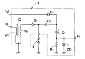
図1は、同時発火タイプの点火コイルを用いる点火装置に本発明を適用した、本発明の第1の実施形態の構成を示したもので、同図において1は点火コイルIGを含む点火コイル側ユニット、2は点火コイルIGの一次電流を制御する回路と点火電源部2Aとを含む点火ユニット、3は点火電源部2Aに電源電圧を与える電源、4A及び4Bは2気筒内燃機関の第1気筒及び第2気筒にそれぞれ取り付けられた第1の点火プラグ及び第2の点火プラグである。内燃機関は2サイクル機関でもよく、4サイクル機関でもよい。
FIG. 1 shows a configuration of a first embodiment of the present invention in which the present invention is applied to an ignition device using a simultaneous ignition type ignition coil. In FIG. 1, 1 is an ignition coil side including an ignition coil IG. A
点火電源部に電源電圧を与える電源3は機関により駆動される発電機内に設けられた点火電源コイルでもよく、バッテリなどの直流電源でもよいが、図示の例では電源3が直流電源からなっている。 The power source 3 for supplying a power source voltage to the ignition power source unit may be an ignition power coil provided in a generator driven by an engine or a DC power source such as a battery. In the illustrated example, the power source 3 is a DC power source. .
更に詳細に説明すると、点火コイル側ユニット1は、一次コイルW1及び二次コイルW2を有する点火コイルIGと、バイアス用コンデンサC1と、逆流阻止用ダイオードD1と、バイアス電圧印加用ダイオードD2と、イオン電流検出用抵抗器R1と、ツェナーダイオードZDとを備えている。点火コイルの一次コイルW1の一端は接地され、他端は点火コンデンサ接続端子1aに接続されている。また二次コイルW2の一端及び他端はそれぞれ第1の出力端子1b及び第2の出力端子1cに接続され、第1の出力端子1b及び第2の出力端子1cがそれぞれ図示しない内燃機関の第1気筒に取り付けられた第1の点火プラグ4Aの非接地側端子及び第2気筒に取り付けられた第2の点火プラグ4Bの非接地側端子に高圧コードを介して接続されている。
More specifically, the ignition coil side unit 1 includes an ignition coil IG having a primary coil W1 and a secondary coil W2, a bias capacitor C1, a backflow prevention diode D1, a bias voltage application diode D2, an ion A current detection resistor R1 and a Zener diode ZD are provided. One end of the primary coil W1 of the ignition coil is grounded, and the other end is connected to the ignition capacitor connection terminal 1a. Further, one end and the other end of the secondary coil W2 are connected to the first output terminal 1b and the second output terminal 1c, respectively, and the first output terminal 1b and the second output terminal 1c are respectively connected to the first output terminal of the internal combustion engine (not shown). A non-grounded side terminal of the
またバイアス用コンデンサC1は、イオン電流を検出する際に点火プラグにバイアス電圧を印加するために設けられたコンデンサで、その一端は逆流阻止用ダイオードD1のカソードに接続され、他端は、イオン電流検出用抵抗器R1を通して接地されている。逆流阻止用ダイオードD1のアノードは電源電圧入力用端子1dに接続されている。バイアス電圧印加用ダイオードD2は、バイアス用コンデンサC1の一端と点火コイルの二次コイルW2の他端との間にカソードを二次コイルW2側に向けて接続され、バイアス用コンデンサC1の両端に得られるバイアス電圧が、ダイオードD2と、二次コイルW2と、イオン電流検出用抵抗器R1とを通して第1の点火プラグ4Aに印加されるとともに、ダイオードD2とイオン電流検出用抵抗器R1とを通して第2の点火プラグ4Bの両端に印加されている。
The bias capacitor C1 is a capacitor provided to apply a bias voltage to the spark plug when detecting the ion current. One end of the capacitor C1 is connected to the cathode of the backflow prevention diode D1, and the other end is connected to the ion current. It is grounded through the detection resistor R1. The anode of the reverse current blocking diode D1 is connected to the power supply
この例では、ダイオードD2と抵抗器R1とにより、バイアス用コンデンサC1の両端に得られるバイアス電圧を点火プラグ4A,4Bの両端に印加するバイアス電圧印加回路が構成されている。
In this example, the diode D2 and the resistor R1 constitute a bias voltage application circuit that applies a bias voltage obtained across the bias capacitor C1 across the
ツェナーダイオードZDは、そのカソードを接地側に向けた状態でイオン電流検出用抵抗器R1の両端に並列に接続され、バイアス用コンデンサC1とイオン電流検出用抵抗器R1との接続点が検出信号出力端子1e に接続されている。 The Zener diode ZD is connected in parallel to both ends of the ion current detection resistor R1 with its cathode facing the ground side, and the connection point between the bias capacitor C1 and the ion current detection resistor R1 is the detection signal output. Connected to terminal 1e.
点火ユニット2は、点火電源部2Aの外に、点火コンデンサCaと、放電用スイッチを構成するサイリスタThと、ダイオードDaと、バイアス用コンデンサの充電電流を制限する電流制限用抵抗器R2と、CPUを備えた制御部2Bと、該制御部2Bへの入力信号を制御部2Bを構成するCPUが認識し得る信号に変換するインターフェース回路2Cとを備えている。
In addition to the ignition
点火電源部2Aは、点火コンデンサCaを充電するための二百数十ボルトの直流電圧を出力する回路で、図示の例では、この点火電源部が、直流電源から与えられる直流電圧を昇圧する昇圧回路(DC/DCコンバータ回路)からなっている。この昇圧回路としては、例えば、特許第3191697号公報に示されたような公知のものを用いることができる。
The ignition
点火電源部(昇圧回路)2Aの負極性側出力端子2A1は接地され、その正極性側出力端子2A2は点火コンデンサCaの一端に接続されている。点火コンデンサCaの他端は、点火ユニットの点火コイル接続端子2aに接続され、該点火コイル接続端子2aがリード線を通して点火コイル側ユニット1の点火コンデンサ接続端子1aに接続されている。
The negative output terminal 2A1 of the ignition power supply (boost circuit) 2A is grounded, and the positive output terminal 2A2 is connected to one end of the ignition capacitor Ca. The other end of the ignition capacitor Ca is connected to the ignition
また点火コンデンサCaの一端と接地間に、放電用スイッチを構成するサイリスタThがそのカソードを接地側に向けて接続され、点火コンデンサCaの他端と接地間にダイオードDaがそのカソードを接地側に向けて接続されている。電流制限用抵抗器R2は、その一端を点火電源部2Aの正極性側出力端子2A2に接続した状態で設けられ、該抵抗器R2の他端は点火ユニットの電源出力端子2bに接続されている。電源出力端子2bは、リード線を通して点火コイル側ユニット1の電源電圧入力用端子1dに接続されている。
A thyristor Th constituting a discharge switch is connected between one end of the ignition capacitor Ca and the ground with its cathode facing the ground side, and a diode Da is connected between the other end of the ignition capacitor Ca and the ground so that the cathode is grounded. Connected towards. The current limiting resistor R2 is provided with one end connected to the positive output terminal 2A2 of the
点火コンデンサCaは、点火電源部2Aが出力する点火電源充電用直流電圧により、ダイオードDaを通して図示の極性に充電される。
The ignition capacitor Ca is charged to the illustrated polarity through the diode Da by the ignition power supply DC voltage output from the ignition
制御部2BはCPUを備えていて、各種の制御条件に対して機関の点火時期を演算し、機関のクランク角が演算した点火時期に相当する角度に一致したことを検出したときにサイリスタThに点火信号Stを与える。
The
サイリスタThに点火信号が与えられると、該サイリスタが導通するため、点火コンデンサCaに蓄積された電荷がサイリスタThと点火コイルの一次コイルW1とを通して放電し、図に波線矢印で示した放電電流I1が流れる。これにより点火コイルの一次コイルに瞬間的に大きな電流が流れるため、その二次コイルW2に点火用高電圧が誘起する。この高電圧は点火プラグ4A及び4Bに印加されるため、両点火プラグで同時に火花放電が生じ、図に波線で示したように、二次コイルW2−点火プラグ4B−接地回路−点火プラグ4A−二次コイルW2の経路で火花放電電流I2が流れる。この火花放電電流I2は、点火コイルの二次コイルW2をその一端側から他端側に流れる。
When an ignition signal is applied to the thyristor Th, the thyristor is turned on, so that the charge accumulated in the ignition capacitor Ca is discharged through the thyristor Th and the primary coil W1 of the ignition coil, and a discharge current I1 indicated by a wavy arrow in the figure. Flows. As a result, a large current instantaneously flows through the primary coil of the ignition coil, so that a high voltage for ignition is induced in the secondary coil W2. Since this high voltage is applied to the
昇圧回路を用いた点火電源部は、直流電圧を継続的に出力することができるが、点火電源部から直流電圧を出力させたままの状態にしておくと、内燃機関の点火時期に導通したサイリスタThをターンオフさせることができなくなるため、この種のコンデンサ放電式内燃機関用点火装置では、点火時期にサイリスタThに点火信号を与えると同時に、昇圧回路の動作を停止させて、点火電源部2Aの出力を停止させるようにしている。 The ignition power supply unit using the booster circuit can continuously output a DC voltage. However, if the DC voltage is output from the ignition power supply unit, the thyristor that is conducted at the ignition timing of the internal combustion engine. Since it is impossible to turn off Th, this type of capacitor discharge internal combustion engine ignition device applies an ignition signal to the thyristor Th at the ignition timing, and at the same time stops the operation of the booster circuit, The output is stopped.
そのため点火電源部2Aを構成する昇圧回路は動作停止指令入力端子2A3を有していて、この入力端子に制御部2Bから動作停止指令信号Scが入力されている。昇圧回路は、制御部2Bから動作停止指令信号Scが与えられている間昇圧動作を停止して、点火コンデンサ充電用直流電圧の出力を停止する。
Therefore, the booster circuit constituting the ignition
点火コイル側ユニット1に設けられたバイアス用コンデンサC1は、点火電源部2Aの出力により、抵抗器R2とダイオードD1とツェナーダイオードZD及びイオン電流検出用抵抗器R1とを通して図示の極性に充電される。このように、本発明においては、バイアス用コンデンサC1を火花放電電流により充電するのではなく、点火電源部2Aの出力で充電するため、バイアス用コンデンサC1として静電容量が大きいものを用いても、該コンデンサを十分に充電することができる。
A bias capacitor C1 provided in the ignition coil side unit 1 is charged with the polarity shown in the figure through the resistor R2, the diode D1, the Zener diode ZD, and the ion current detection resistor R1 by the output of the ignition
逆流阻止用ダイオードD1は、点火コンデンサCaの放電時にバイアス用コンデンサC1の電荷が点火コンデンサCa側に放電して、バイアス用コンデンサの両端の電圧が低下するのを防ぐために設けられている。すなわち、逆流阻止用ダイオードD1が設けられていると、点火コンデンサCaの放電により該点火コンデンサの両端の電圧が低下したときにバイアス用コンデンサC1の電荷が点火コンデンサCa側に放電するのを阻止することができるため、点火コンデンサの放電時にバイアス用コンデンサC1の電圧が低下することはない。 The backflow prevention diode D1 is provided in order to prevent the voltage of the bias capacitor C1 from being discharged toward the ignition capacitor Ca when the ignition capacitor Ca is discharged, and the voltage across the bias capacitor being lowered. That is, when the backflow prevention diode D1 is provided, the electric charge of the bias capacitor C1 is prevented from being discharged to the ignition capacitor Ca side when the voltage across the ignition capacitor is reduced by the discharge of the ignition capacitor Ca. Therefore, the voltage of the bias capacitor C1 does not drop when the ignition capacitor is discharged.
またバイアス電圧印加用ダイオードD2が設けられているため、点火コイルの二次コイルに誘起する点火用高電圧がバイアス用コンデンサC1に印加されることはない。 Further, since the bias voltage application diode D2 is provided, the high ignition voltage induced in the secondary coil of the ignition coil is not applied to the bias capacitor C1.
前述のように内燃機関の点火時期にサイリスタThが導通して点火コイルの二次コイルに点火用高電圧が誘起し、点火プラグ4A及び4Bの電極間で火花放電が生じると、両点火プラグが取り付けられた気筒のうち、点火時期にある方の気筒内でガソリンに着火して火炎核が生じ、該気筒内で火炎が伝搬して燃焼が広がっていく。この火炎伝搬が進むと、点火プラグの電極付近のイオン濃度が増加するため、バイアス用コンデンサC1から印加されるバイアス電圧により、点火時期にある気筒に取り付けられた点火プラグとイオン電流検出用抵抗器R1とを通してイオン電流Iiが流れる。
As described above, when the thyristor Th is conducted at the ignition timing of the internal combustion engine and a high voltage for ignition is induced in the secondary coil of the ignition coil, and spark discharge occurs between the electrodes of the
図示の例では、点火プラグ4Bが取り付けられた気筒が点火時期にあり、バイアス用コンデンサの両端に得られるバイアス電圧により、点火プラグ4Bを通してイオン電流Iiが流れている。このイオン電流によりイオン電流検出用抵抗器R1の両端に電圧降下が生じるため、該抵抗器R1の両端の電圧Vsを検出信号として取り出すことにより、イオン電流を検出することができる。
In the illustrated example, the cylinder to which the
図示の例では、点火コイル側ユニット1に設けられた検出信号出力端子1eが点火ユニットに設けられた検出信号入力端子2cにリード線を通して接続されていて、抵抗器R1の両端の電圧Vsがインターフェース回路2Cを通して、イオン電流検出信号として、制御部2BのCPUに入力されている。この例では、イオン電流検出用抵抗器R1と、ツェナーダイオードZDと、インターフェース回路2Cとにより、イオン電流検出回路が構成されている。
In the illustrated example, the detection
なおツェナーダイオードZDは、バイアス用コンデンサC1の初期充電時にインターフェース回路2Cに過大な電圧が入力されるのを防ぐとともに、機関の運転時に予期しない大きさのイオン電流によりインターフェース回路に過大な電圧が入力されるのを防ぐために設けられたもので、そのツェナー電圧は、機関の定常運転時に流れることが予想される最大イオン電流により抵抗R1の両端に生じる電圧降下よりは高く設定されている。 The Zener diode ZD prevents an excessive voltage from being input to the interface circuit 2C when the bias capacitor C1 is initially charged, and an excessive voltage is input to the interface circuit due to an unexpectedly large ion current during engine operation. The Zener voltage is set higher than the voltage drop that occurs across the resistor R1 due to the maximum ion current that is expected to flow during steady engine operation.
内燃機関において、点火プラグ4A及び4Bが機関の異なる気筒に取り付けられている場合には、点火プラグ4A及び4Bが取り付けられた2つの気筒のうちの一方が点火時期にある時に、他方は点火時期にないため、両気筒で同時に燃焼が起こることはない。点火時期にない気筒では、点火プラグで火花放電が生じても燃焼が起こらず、点火プラグの電極付近でイオンが発生することは無いため、点火時期にない気筒に取り付けられた点火プラグにバイアス用コンデンサC1からバイアス電圧が印加されてもイオン電流が流れることはない。従って、同時発火タイプの点火コイルが用いられる場合でも、イオン電流検出回路を1つ設けるだけで、2つの点火プラグのそれぞれを通して流れるイオン電流を測定することができる。
In the internal combustion engine, when the
また制御部2Bが気筒判別手段を備えていて、該気筒判別手段により、各点火時期が2つの気筒のうちの何れの気筒で点火を行う点火時期であるかの判別が行われる場合には、測定されたイオン電流が何れの気筒のイオン電流であるかを判別することができる。
Further, when the
本実施形態では、制御部2Bに点火電源部制御手段が設けられていて、この制御手段により、少なくとも内燃機関の点火時期からイオン電流の検出が完了する時期までの間点火電源部2Aに動作停止指令信号Scが与えらるようになっている。
In this embodiment, the
イオン電流の検出が終了して、制御部2Bから点火電源部2Aに与えられていた動作停止指令信号が消滅すると、点火電源部2Aが点火コンデンサ充電用直流電圧の出力を再開し、点火コンデンサCaの充電と、バイアス用コンデンサC1の充電とを開始する。
When the detection of the ionic current is completed and the operation stop command signal supplied from the
図1に示した実施形態では、2つの点火プラグが機関の異なる気筒に取り付けられているとしたが、両点火プラグは、機関の同じ気筒に取り付けられていてもよい。点火プラグ4A,4Bが機関の同じ気筒に取り付けられている場合には、点火プラグ4Aの電極間及び点火プラグ4Bの電極間を通して流れるイオン電流がイオン電流がイオン電流検出回路により検出される。
In the embodiment shown in FIG. 1, two spark plugs are attached to different cylinders of the engine. However, both spark plugs may be attached to the same cylinder of the engine. When the
上記の実施形態では、点火電源部2Aが直流電圧を昇圧する昇圧回路により構成されているが、機関に取り付けられた磁石発電機内に設けられたエキサイタコイルと、該エキサイタコイルの出力を整流するダイオードとにより点火電源部を構成する場合にも本発明を適用することができる。この場合は、点火時に点火電源部が電圧を出力しないため、制御部が点火電源部の出力を停止させるための制御を行う必要はない。
In the above embodiment, the ignition
上記の実施形態では、点火コイルとして同時発火形のものを用いたが、点火コイルの二次コイルに単一の点火プラグのみを負荷する場合にも本発明を適用することができる。点火コイルの二次コイルに1つの点火プラグ4のみが接続される場合の点火コイル側ユニット1の構成を図2に示した。 In the above embodiment, the simultaneous ignition type is used as the ignition coil. However, the present invention can be applied to the case where only a single spark plug is loaded on the secondary coil of the ignition coil. The configuration of the ignition coil side unit 1 when only one ignition plug 4 is connected to the secondary coil of the ignition coil is shown in FIG.
図2に示した構成は、点火コイルIGの一次コイルW1の一端及び二次コイルW1の一端が共に接地されている。また点火コイルの二次コイルW2の他端と点火プラグ4の非接地側端子との間に、火花放電電流通電用ダイオードD3が、そのアノードを二次コイル側に向けた状態で挿入されている。その他の点は図1に示した例と全く同様に構成されている。 In the configuration shown in FIG. 2, one end of the primary coil W1 and one end of the secondary coil W1 are both grounded. Further, a spark discharge current conducting diode D3 is inserted between the other end of the secondary coil W2 of the ignition coil and the non-grounded terminal of the spark plug 4 with the anode facing the secondary coil. . Other points are the same as those of the example shown in FIG.
上記の実施形態では、点火コンデンサが点火コイルの一次コイルに対して直列に接続され、サイリスタが点火コンデンサを介して一次コイルに対して並列に接続されているが、点火コンデンサとサイリスタの位置を入れ替えた構成をとるコンデンサ放電式の点火装置にも本発明を適用することができる。 In the above embodiment, the ignition capacitor is connected in series to the primary coil of the ignition coil, and the thyristor is connected in parallel to the primary coil via the ignition capacitor, but the positions of the ignition capacitor and thyristor are switched. The present invention can also be applied to a capacitor discharge type ignition device having such a configuration.
また上記の実施形態では、放電用スイッチとしてサイリスタを用いているが、FETなどの他のスイッチ素子により放電用スイッチを構成する場合にも本発明を適用することができる。 In the above embodiment, the thyristor is used as the discharge switch. However, the present invention can also be applied to the case where the discharge switch is configured by other switch elements such as FETs.
1 点火コイル側ユニット
2 点火ユニット
2A 点火電源部
2B 制御部
4 点火プラグ
4A 第1の点火プラグ
4B 第2の点火プラグ
C1 バイアス用コンデンサ
R1 イオン電流検出用抵抗器
IG 点火コイル
Ca 点火コンデンサ
Th サイリスタ(放電用スイッチ)
D1 逆流阻止用ダイオード
D2 バイアス電圧印加用ダイオード
D3 火花放電電流通電用ダイオード
1 ignition
D1 Backflow prevention diode D2 Bias voltage application diode D3 Spark discharge current conduction diode
Claims (4)
前記点火電源部の出力により逆流阻止用ダイオードを通して充電されるバイアス用コンデンサと、前記バイアス用コンデンサの両端に得られるバイアス電圧を前記点火プラグの両端に印加するバイアス電圧印加回路と、前記バイアス電圧により前記点火プラグの電極間を通して流れるイオン電流を検出するイオン電流検出回路とを備え、
前記制御部は、少なくとも前記内燃機関の点火時期から前記イオン電流の検出が完了する時期までの間前記点火電源部が点火コンデンサ充電用直流電圧を出力するのを禁止するように前記点火電源部を制御する点火電源部制御手段を備えているコンデンサ放電式内燃機関用点火装置。 An ignition coil in which at least one ignition plug is loaded on the secondary coil, an ignition power supply unit that outputs a DC voltage for charging the ignition capacitor, and a voltage provided on the primary side of the ignition coil and obtained from the ignition power supply unit An ignition capacitor that is charged to one polarity, a discharge switch that conducts when an ignition signal is applied and discharges the charge of the ignition capacitor through the primary coil of the ignition coil, and the ignition timing of the internal combustion engine In an ignition device for a capacitor discharge internal combustion engine comprising a control unit having means for giving the ignition signal to a discharge switch,
A bias capacitor charged through a backflow prevention diode by the output of the ignition power supply unit, a bias voltage application circuit for applying a bias voltage obtained at both ends of the bias capacitor to both ends of the ignition plug, and the bias voltage An ion current detection circuit for detecting an ion current flowing between the electrodes of the spark plug ;
The control unit controls the ignition power source unit to prohibit the ignition power source unit from outputting a DC voltage for charging an ignition capacitor at least from an ignition timing of the internal combustion engine to a timing when the detection of the ion current is completed. An ignition device for a capacitor discharge internal combustion engine comprising ignition power source control means for controlling .
前記点火電源部の正極性側の出力端子にアノードを向けた逆流阻止用ダイオードを通して該点火電源部の正極性側出力端子に一端が接続され、他端がイオン電流検出用抵抗器を通して接地されたバイアス用コンデンサと、前記バイアス用コンデンサの一端と前記点火コイルの二次コイルの他端との間にカソードを前記二次コイル側に向けて接続されたバイアス電圧印加用ダイオードと、前記バイアス用コンデンサから前記バイアス電圧印加用ダイオードを通して前記第1の点火プラグ及び第2の点火プラグに印加される電圧により前記第1の点火プラグの電極間及び(または)第2の点火プラグの電極間を通して流れるイオン電流を前記イオン電流検出用抵抗器の両端の電圧から検出するイオン電流検出回路とを備え、
前記制御部は、少なくとも前記内燃機関の点火時期から前記イオン電流の検出が完了する時期までの間前記点火電源部が点火コンデンサ充電用直流電圧を出力するのを禁止するように前記点火電源部を制御する点火電源部制御手段を備えているコンデンサ放電式内燃機関用点火装置。 An ignition coil in which one end of the primary coil is grounded and the non-ground side terminal of the first spark plug and the non-ground side terminal of the second spark plug are connected to one end and the other end of the secondary coil, respectively, and the negative polarity side An ignition power supply unit that outputs a DC voltage for charging an ignition capacitor, and is provided on the primary side of the ignition coil and is set to one polarity by a voltage obtained from the ignition power supply unit. An ignition capacitor to be charged; a discharge switch that conducts when an ignition signal is applied and discharges the charge of the ignition capacitor through a primary coil of the ignition coil; and the discharge switch at the ignition timing of the internal combustion engine A spark discharge current that flows when a high voltage is induced in the secondary coil of the ignition coil by discharging the charge of the ignition capacitor. The ignition device for capacitor discharge type internal combustion engine that is configured to flow from one end to the other end of the secondary coil of the ignition coil,
One end of the ignition power supply unit is connected to the positive output terminal of the ignition power supply unit through a backflow prevention diode having an anode directed to the positive output terminal, and the other end is grounded through an ion current detection resistor. A bias capacitor, a bias voltage applying diode connected between one end of the bias capacitor and the other end of the secondary coil of the ignition coil with the cathode facing the secondary coil, and the bias capacitor To flow between the electrodes of the first spark plug and / or between the electrodes of the second spark plug by a voltage applied to the first spark plug and the second spark plug through the bias voltage applying diode from An ion current detection circuit for detecting current from the voltage across the ion current detection resistor ,
The control unit controls the ignition power source unit to prohibit the ignition power source unit from outputting a DC voltage for charging an ignition capacitor at least from an ignition timing of the internal combustion engine to a timing when the detection of the ion current is completed. An ignition device for a capacitor discharge internal combustion engine comprising ignition power source control means for controlling .
前記点火コイルの二次コイルの前記他端と前記点火プラグの非接地側端子との間にアノードを前記二次コイル側に向けて挿入された火花放電電流通電用ダイオードと、前記点火電源部の正極性側の出力端子にアノードを向けた逆流阻止用ダイオードを通して該点火電源部の正極性側出力端子に一端が接続され、他端がイオン電流検出用抵抗器を通して接地されたバイアス用コンデンサと、前記バイアス用コンデンサの一端と前記点火プラグの非接地側端子との間にアノードを前記バイアス用コンデンサ側に向けて接続されたバイアス電圧印加用ダイオードと、前記バイアス用コンデンサから前記バイアス電圧印加用ダイオードを通して前記点火プラグに印加される電圧により、該点火プラグの電極間を通して流れるイオン電流を前記イオン電流検出用抵抗器の両端の電圧から検出するイオン電流検出回路とを備え、
前記制御部は、少なくとも前記内燃機関の点火時期から前記イオン電流の検出が完了する時期までの間前記点火電源部が点火コンデンサ充電用直流電圧を出力するのを禁止するように前記点火電源部を制御する点火電源部制御手段を備えているコンデンサ放電式内燃機関用点火装置。 Provided with one end of the primary coil and one end of the secondary coil grounded, the other end of the secondary coil connected to the non-ground side terminal of the spark plug, and the negative output terminal grounded An ignition power supply unit that outputs a DC voltage for charging the ignition capacitor, an ignition capacitor that is provided on the primary side of the ignition coil and is charged to one polarity by a voltage obtained from the ignition power supply unit, and an ignition signal A discharge switch that conducts when given and discharges the charge of the ignition capacitor through a primary coil of the ignition coil; and a control unit that has means for giving the ignition signal to the discharge switch at the ignition timing of the internal combustion engine; A spark discharge current that flows when a high voltage is induced in the secondary coil of the ignition coil due to the discharge of the electric charge of the ignition capacitor. The ignition device for capacitor discharge type internal combustion engine that is configured to flow from one end to the other end of the le,
A spark discharge current conducting diode inserted between the other end of the secondary coil of the ignition coil and a non-grounded side terminal of the spark plug with the anode facing the secondary coil; and A bias capacitor having one end connected to a positive output terminal of the ignition power supply unit through a backflow prevention diode having an anode directed to an output terminal on the positive polarity side, and the other end grounded through an ion current detection resistor; A bias voltage application diode having an anode connected to one end of the bias capacitor and a non-ground side terminal of the spark plug toward the bias capacitor side; and the bias voltage application diode from the bias capacitor Through the voltage applied to the spark plug through the ionic current flowing between the electrodes of the spark plug, A ion current detection circuit for detecting the voltage across the detecting resistor,
The control unit controls the ignition power source unit to prohibit the ignition power source unit from outputting a DC voltage for charging an ignition capacitor at least from an ignition timing of the internal combustion engine to a timing when the detection of the ion current is completed. An ignition device for a capacitor discharge internal combustion engine comprising ignition power source control means for controlling .
Priority Applications (1)
| Application Number | Priority Date | Filing Date | Title |
|---|---|---|---|
| JP2003281130A JP4352223B2 (en) | 2003-07-28 | 2003-07-28 | Ignition system for capacitor discharge internal combustion engine |
Applications Claiming Priority (1)
| Application Number | Priority Date | Filing Date | Title |
|---|---|---|---|
| JP2003281130A JP4352223B2 (en) | 2003-07-28 | 2003-07-28 | Ignition system for capacitor discharge internal combustion engine |
Publications (2)
| Publication Number | Publication Date |
|---|---|
| JP2005048649A JP2005048649A (en) | 2005-02-24 |
| JP4352223B2 true JP4352223B2 (en) | 2009-10-28 |
Family
ID=34266738
Family Applications (1)
| Application Number | Title | Priority Date | Filing Date |
|---|---|---|---|
| JP2003281130A Expired - Fee Related JP4352223B2 (en) | 2003-07-28 | 2003-07-28 | Ignition system for capacitor discharge internal combustion engine |
Country Status (1)
| Country | Link |
|---|---|
| JP (1) | JP4352223B2 (en) |
Cited By (1)
| Publication number | Priority date | Publication date | Assignee | Title |
|---|---|---|---|---|
| JP2012117375A (en) * | 2010-11-29 | 2012-06-21 | Hanshin Electric Co Ltd | Ion current detecting device for internal combustion engine |
Families Citing this family (4)
| Publication number | Priority date | Publication date | Assignee | Title |
|---|---|---|---|---|
| KR100957743B1 (en) * | 2005-06-13 | 2010-05-12 | 스티벨엘트론게엠베하운트콤파니카게 | Circuit for detecting combustion-related variables |
| JP2012237283A (en) * | 2011-05-13 | 2012-12-06 | Mitsubishi Electric Corp | Ion current detector |
| WO2014083712A1 (en) * | 2012-11-30 | 2014-06-05 | 日立オートモティブシステムズ阪神株式会社 | Ignition device for internal combustion engine |
| JP2023502557A (en) * | 2019-11-27 | 2023-01-25 | ティーヴィーエス モーター カンパニー リミテッド | Misfire detection system for internal combustion engines |
-
2003
- 2003-07-28 JP JP2003281130A patent/JP4352223B2/en not_active Expired - Fee Related
Cited By (1)
| Publication number | Priority date | Publication date | Assignee | Title |
|---|---|---|---|---|
| JP2012117375A (en) * | 2010-11-29 | 2012-06-21 | Hanshin Electric Co Ltd | Ion current detecting device for internal combustion engine |
Also Published As
| Publication number | Publication date |
|---|---|
| JP2005048649A (en) | 2005-02-24 |
Similar Documents
| Publication | Publication Date | Title |
|---|---|---|
| US6779517B2 (en) | Ignition device for internal combustion engine | |
| US6539930B2 (en) | Ignition apparatus for internal combustion engine | |
| US7559319B2 (en) | Ignition coil apparatus for an internal combustion engine | |
| JP3330838B2 (en) | Device for detecting combustion state of internal combustion engine | |
| JP2008522066A (en) | Fast multi-spark ignition | |
| JPH09324735A (en) | Combustion state detector for internal combustion engine | |
| JP2000199451A (en) | Combustion status detecting device for internal combustion engine | |
| JPH10231771A (en) | Combustion state detector for internal combustion engine | |
| JP4352223B2 (en) | Ignition system for capacitor discharge internal combustion engine | |
| US5294888A (en) | Device for detecting misfire of an internal combustion engine by comparing voltage waveforms associated with ignition system | |
| JP3449972B2 (en) | Misfire detection device for internal combustion engine | |
| JP2641798B2 (en) | Ion current detector | |
| JP3351932B2 (en) | Method and apparatus for detecting combustion state of internal combustion engine | |
| JP2688672B2 (en) | Misfire detection device for internal combustion engine | |
| JP2003286933A (en) | Ignition device for internal combustion engine | |
| JP4296856B2 (en) | Ignition unit for internal combustion engine | |
| JP2525979B2 (en) | Gasoline engine combustion condition detector | |
| JP4567878B2 (en) | Ignition device for internal combustion engine | |
| JP3619073B2 (en) | Combustion state detection device for internal combustion engine | |
| JP2002221139A (en) | Ignition device for internal combustion engine | |
| JP3186327B2 (en) | Ion current detector | |
| JPH04134181A (en) | Ion current detecting device | |
| JPH09144641A (en) | Ion current detecting circuit for internal combustion engine | |
| JP3120392B1 (en) | Ignition device having engine misfire detection function | |
| JP2641997B2 (en) | Misfire detection device for internal combustion engine |
Legal Events
| Date | Code | Title | Description |
|---|---|---|---|
| A621 | Written request for application examination |
Free format text: JAPANESE INTERMEDIATE CODE: A621 Effective date: 20060725 |
|
| A977 | Report on retrieval |
Free format text: JAPANESE INTERMEDIATE CODE: A971007 Effective date: 20090226 |
|
| A131 | Notification of reasons for refusal |
Free format text: JAPANESE INTERMEDIATE CODE: A131 Effective date: 20090317 |
|
| A521 | Written amendment |
Free format text: JAPANESE INTERMEDIATE CODE: A523 Effective date: 20090513 |
|
| TRDD | Decision of grant or rejection written | ||
| A01 | Written decision to grant a patent or to grant a registration (utility model) |
Free format text: JAPANESE INTERMEDIATE CODE: A01 Effective date: 20090701 |
|
| A01 | Written decision to grant a patent or to grant a registration (utility model) |
Free format text: JAPANESE INTERMEDIATE CODE: A01 |
|
| A61 | First payment of annual fees (during grant procedure) |
Free format text: JAPANESE INTERMEDIATE CODE: A61 Effective date: 20090714 |
|
| R150 | Certificate of patent or registration of utility model |
Free format text: JAPANESE INTERMEDIATE CODE: R150 |
|
| FPAY | Renewal fee payment (event date is renewal date of database) |
Free format text: PAYMENT UNTIL: 20120807 Year of fee payment: 3 |
|
| FPAY | Renewal fee payment (event date is renewal date of database) |
Free format text: PAYMENT UNTIL: 20120807 Year of fee payment: 3 |
|
| FPAY | Renewal fee payment (event date is renewal date of database) |
Free format text: PAYMENT UNTIL: 20130807 Year of fee payment: 4 |
|
| R250 | Receipt of annual fees |
Free format text: JAPANESE INTERMEDIATE CODE: R250 |
|
| R250 | Receipt of annual fees |
Free format text: JAPANESE INTERMEDIATE CODE: R250 |
|
| R250 | Receipt of annual fees |
Free format text: JAPANESE INTERMEDIATE CODE: R250 |
|
| R250 | Receipt of annual fees |
Free format text: JAPANESE INTERMEDIATE CODE: R250 |
|
| LAPS | Cancellation because of no payment of annual fees |