JP2008522066A - Fast multi-spark ignition - Google Patents
Fast multi-spark ignition Download PDFInfo
- Publication number
- JP2008522066A JP2008522066A JP2007541759A JP2007541759A JP2008522066A JP 2008522066 A JP2008522066 A JP 2008522066A JP 2007541759 A JP2007541759 A JP 2007541759A JP 2007541759 A JP2007541759 A JP 2007541759A JP 2008522066 A JP2008522066 A JP 2008522066A
- Authority
- JP
- Japan
- Prior art keywords
- ignition
- control unit
- transformer
- spark
- time
- Prior art date
- Legal status (The legal status is an assumption and is not a legal conclusion. Google has not performed a legal analysis and makes no representation as to the accuracy of the status listed.)
- Abandoned
Links
Images


Classifications
-
- F—MECHANICAL ENGINEERING; LIGHTING; HEATING; WEAPONS; BLASTING
- F02—COMBUSTION ENGINES; HOT-GAS OR COMBUSTION-PRODUCT ENGINE PLANTS
- F02P—IGNITION, OTHER THAN COMPRESSION IGNITION, FOR INTERNAL-COMBUSTION ENGINES; TESTING OF IGNITION TIMING IN COMPRESSION-IGNITION ENGINES
- F02P15/00—Electric spark ignition having characteristics not provided for in, or of interest apart from, groups F02P1/00 - F02P13/00 and combined with layout of ignition circuits
- F02P15/08—Electric spark ignition having characteristics not provided for in, or of interest apart from, groups F02P1/00 - F02P13/00 and combined with layout of ignition circuits having multiple-spark ignition, i.e. ignition occurring simultaneously at different places in one engine cylinder or in two or more separate engine cylinders
-
- F—MECHANICAL ENGINEERING; LIGHTING; HEATING; WEAPONS; BLASTING
- F02—COMBUSTION ENGINES; HOT-GAS OR COMBUSTION-PRODUCT ENGINE PLANTS
- F02P—IGNITION, OTHER THAN COMPRESSION IGNITION, FOR INTERNAL-COMBUSTION ENGINES; TESTING OF IGNITION TIMING IN COMPRESSION-IGNITION ENGINES
- F02P3/00—Other installations
- F02P3/02—Other installations having inductive energy storage, e.g. arrangements of induction coils
Abstract
本発明は高速マルチスパーク点火に関し、その間、スパーク放電用の最大放電電圧が点火時間ウィンドウ間に繰り返し得られる。本点火装置は、車両電気系統の電圧を上げる直流コンバータによって、およびその最小化された点火コイルにより高速の再充電が可能になるロッド型点火用変圧器によって作動する。点火エレクトロニクスは、一次巻線の接地経路にスイッチイング素子を切り替えることによってロッド型点火用変圧器を充電させるパワー出力ステージにより作動する。その出力ステージのスイッチイング素子はタイマーによって制御されるが、該タイマーは、ロッド型点火用変圧器を充電させるためにスイッチイング素子をクロックし、点火用変圧器の充電後、スパーク放電を達成するために、予め規定された時間、点火用変圧器の一次側を長導電手法(long conductive manner)において接地するように切り替える。 The present invention relates to fast multi-spark ignition, during which the maximum discharge voltage for spark discharge is repeatedly obtained during the ignition time window. The ignition system is operated by a DC converter that raises the voltage of the vehicle electrical system and by a rod-type ignition transformer that allows fast recharging with its minimized ignition coil. The ignition electronics are operated by a power output stage that charges the rod ignition transformer by switching the switching element to the ground path of the primary winding. The switching element of the output stage is controlled by a timer, which clocks the switching element to charge the rod-type ignition transformer and achieves a spark discharge after charging the ignition transformer. Therefore, the primary side of the ignition transformer is switched to ground in a long conductive manner for a predetermined time.
Description
本発明は、スパークプラグにおいて数回のスパーク放電を発生させるための方法、および点火装置に関する。本発明では、スパーク放電は点火時間ウィンドウ内に連続して複数回実行される。 The present invention relates to a method for generating several spark discharges in a spark plug and to an ignition device. In the present invention, the spark discharge is performed a plurality of times continuously within the ignition time window.
スパークプラグにおいてマルチスパーク放電を発生させる装置に関する多くの研究が、点火技術の分野においてなされてきた。そのような点火装置及び点火方法は、例えば、「マルチチャージ装置」あるいは「マルチスパークシステム」と呼ばれている。従って、このようなタイプを形成する多くの公開特許が存在し、その中で最も重要なものを、以下、簡単に説明する。 A lot of research on devices for generating multi-spark discharges in spark plugs has been done in the field of ignition technology. Such an ignition device and ignition method are called, for example, a “multi-charge device” or a “multi-spark system”. Accordingly, there are many published patents that form such a type, the most important of which are briefly described below.
特許文献1は、内燃機関内の点火を制御するための点火方法および点火装置を開示し、その装置は、点火コイルの一次電流を複数回遮断することによって点火コイルの二次側に電圧パルスを発生させ、従って、下流のスパークプラグの電極においてスパーク放電を発生させる。
この場合、スパーク放電を発生させる制御装置は、二次電流を測定し監視する複合測定センサ装置によって作動する。最初のスパーク放電のあと、二次電流が、点火時間ウィンドウ内で、監視される閾値未満に低下した場合、点火コイルは再充電され、新しいスパーク放電が開始される。この場合、監視される閾値は、エンジン回転数および周囲温度の関数である。 In this case, the control device that generates the spark discharge is operated by a combined measurement sensor device that measures and monitors the secondary current. If, after the first spark discharge, the secondary current falls below the monitored threshold within the ignition time window, the ignition coil is recharged and a new spark discharge is initiated. In this case, the monitored threshold is a function of engine speed and ambient temperature.
同様な一般タイプのマルチ充電装置が、特許文献2および特許文献3からも知られている。 Similar general type multi-charging devices are also known from US Pat.
特許文献2において、特許文献1の中で既に言及されている二次電流の閾値は、点火コイルの二次コイルから既に引かれたエネルギーの関数として定義される。結果として、マルチ点火の時間間隔は可変に保たれ、マルチ点火のため過度に高いエネルギーが燃焼シリンダに印加されることが回避される。
In Patent Document 2, the threshold value of the secondary current already mentioned in
特許文献3において、マルチ点火によるエネルギーの不必要な印加を回避するために、異なる方法が追求されている。燃料混合気が既に点火されているかどうかが、イオン電流測定手段を用いて判断される。該手段は、制御ユニットによって、またイオン電流の閾値を考慮することによって、スパークプラグの電極を横切る二次電流を測定する。燃料混合気が既に点火されていると判断された場合、マルチ充電プロセスは終了する。
In
点火時間ウィンドウ内でスパーク持続時間を制御することが可能な交流電流点火も知られている。特許文献4において、一次電流は、時間制御設定機能および一次電流の重ねられた最大電流制限によって複数回遮断される。それにより、AC電圧が、フライバックコンバーター原理に従い、一次電流経路の逆阻止ダイオードによって点火コイルの二次側に発生する。点火コイルの設計のために内在する再点火リザーブにより、点火スパークが消滅したとき、再点火を実行するかどうかが配慮される。
Alternating current ignition is also known which can control the spark duration within the ignition time window. In
上述の点火装置はすべて特有の利点を有するが、必然的に特有の制限も有する。 All of the ignition devices described above have their own advantages, but necessarily have their own limitations.
上述の点火装置および点火方法は、内燃機関が過度の酸素で運転される、所謂、希薄燃焼エンジンまたは内燃機関の層状給気方式(燃料層状噴射)と呼ばれる、内燃機関の低負荷運転には適していない。これらのエンジンの場合、低回転速度時および低負荷状態での失火が非常に目立つ。この場合、導入される燃料の量が減少するので、失火の危険性が増す。低負荷レンジにおいて、混合気を点火させる能力は極めて重大である。今やスパークプラグの接地電極の設置位置でさえ、層状給気を確実に点火させることができるかどうかに決定的な影響を有している。特にアイドリング中あるいは低負荷レンジなどの低回転速度において、スパークの失火が発生した場合、エンジンの極めて不安定な動作が目立つ。これを解決する完全な点火方法が現在まで見出されていないので、希薄燃焼エンジンは、低負荷レンジにおいて擬似的に過濃にされた方法で運転される。しかしながら、結果として、期待された燃費の節約の大部分は、再び見失われる。内燃機関の出力クラスが大きくなるほど、希薄燃焼エンジンのこの部分的負荷問題は大きくなる。 The above ignition device and ignition method are suitable for low-load operation of an internal combustion engine, which is called a lean combustion engine or a stratified charge system (fuel stratified injection) of an internal combustion engine in which the internal combustion engine is operated with excessive oxygen. Not. In these engines, misfires at low rotational speeds and under low load conditions are very noticeable. In this case, the amount of fuel introduced is reduced, increasing the risk of misfire. In the low load range, the ability to ignite the mixture is critical. Now even the location of the spark plug ground electrode has a decisive influence on whether the stratified charge can be ignited reliably. In particular, when a spark misfire occurs during idling or at a low rotational speed such as a low load range, extremely unstable operation of the engine is conspicuous. Since no complete ignition method has been found to date to solve this, lean burn engines are operated in a pseudo-enriched manner in the low load range. However, as a result, most of the expected fuel savings are lost again. The greater the power class of an internal combustion engine, the greater this partial load problem of a lean burn engine.
従って、本発明の1つの目的は、内燃機関の希薄燃焼運転の許容動作点をさらに低負荷レンジに、さらに低エンジン回転数にシフトさせることができる点火方法と点火装置とを提供することである。 Accordingly, one object of the present invention is to provide an ignition method and an ignition device capable of shifting the allowable operating point of the lean combustion operation of the internal combustion engine to a lower load range and further to a lower engine speed. .
この目的は、独立請求項に規定された方法および点火装置によって達成される。本発明のさらに有利な実施形態は、従属請求項および明細書に開示され、好ましい実施態様も開示される。 This object is achieved by a method and an ignition device as defined in the independent claims. Further advantageous embodiments of the invention are disclosed in the dependent claims and the specification and preferred embodiments are also disclosed.
スパークのための最大放電電圧が、点火時間ウィンドウの間、複数回得られる高速マルチスパークによって本発明の目的が達成される。この点火装置は、車載された車両電気系統の電圧を上げるDCコンバータと、その小型化された点火コイルによって高速の再充電が可能になるロッド型点火用変圧器によって作動する。点火エレクトロニクスはパワー出力ステージにより作動し、一次巻線の接地経路への接続をスイッチイング素子により切り替えることによって、ロッド型点火用変圧器を充電する。出力ステージのスイッチイング素子は、ロッド型点火用変圧器を充電するようにクロック制御された時間制御設定機能によって作動され、点火用変圧器の充電後、スパーク放電を達成するために予め指定された時間の間、点火用変圧器の一次側を接地する。 The object of the invention is achieved by a fast multi-spark in which the maximum discharge voltage for the spark is obtained several times during the ignition time window. This ignition device is operated by a DC converter that raises the voltage of a vehicle electric system mounted on a vehicle and a rod-type ignition transformer that can be recharged at high speed by its miniaturized ignition coil. The ignition electronics are operated by a power output stage and charge the rod-type ignition transformer by switching the connection of the primary winding to the ground path with a switching element. The output stage switching element is activated by a clocked time control setting function to charge the rod-type ignition transformer and is pre-designated to achieve a spark discharge after the ignition transformer is charged. During the time, the primary side of the ignition transformer is grounded.
時間制御設定機能を実現するいくつかの方法がある。1つの実施形態では、時間制御設定機能は、点火用変圧器を充電するためのドライバ回路のパワー出力ステージの作動を引き継ぐ別個の点火制御ユニット内に実装され得る。この場合、上位のエンジン制御ユニットが点火制御ユニットに対して、高速マルチ噴射の開始および終了について点火時間ウィンドウを予め指定する。 There are several ways to implement the time control setting function. In one embodiment, the time control setting function may be implemented in a separate ignition control unit that takes over the operation of the power output stage of the driver circuit for charging the ignition transformer. In this case, the host engine control unit pre-designates the ignition time window for the start and end of the high-speed multi-injection to the ignition control unit.
しかしながら、点火制御機能は、いずれの場合も自動車内に存在する制御ユニット内に実装されると好ましい。ここではエンジン制御ユニットが最適である。点火制御機能がエンジン制御ユニット内に実装された場合、別個の点火制御ユニットが不要になるだけでなく、点火時間ウィンドウ用の信号とパワー出力ステージを作動させるための信号とを組み合わせて標準化することも可能である。これによって、信号処理が大幅に簡素化される。 However, the ignition control function is preferably implemented in a control unit that exists in the automobile in any case. The engine control unit is optimal here. When the ignition control function is implemented in the engine control unit, not only a separate ignition control unit is required, but also a standardized combination of the signal for the ignition time window and the signal for operating the power output stage Is also possible. This greatly simplifies signal processing.
ロッド型点火用変圧器の小さなコイルが、DCコンバータと共に、高速の再充電を可能にする。昇圧制御器のようなDCコンバータが、点火のために車載電気系統電圧を昇圧し、一般的な公称電圧14Vよりもかなり高い入力電圧を、ロッド型点火用変圧器の一次側に供給する。少なくとも28ボルト以上の一次側の入力電圧が好ましい。一般に、一次側の入力電圧が高いほど、点火コイルは速く再充電される。 The small coil of the rod ignition transformer, together with the DC converter, allows for fast recharging. A DC converter, such as a boost controller, boosts the in-vehicle electrical system voltage for ignition and supplies an input voltage that is significantly higher than the typical nominal voltage of 14V to the primary side of the rod-type ignition transformer. A primary input voltage of at least 28 volts or more is preferred. In general, the higher the input voltage on the primary side, the faster the ignition coil is recharged.
パワーエレクトロニクスおよびロッド型点火用変圧器は、当該内燃機関の点火時間ウィンドウ内に、スパークプラグにおけるスパーク放電のための最大放電電圧に少なくとも3回到達するように設計される。スパーク放電のための最大放電電圧が、点火時間ウィンドウ内に10〜12回印加されるように設計されることがより好ましい。 The power electronics and rod-type ignition transformer are designed to reach the maximum discharge voltage for the spark discharge in the spark plug at least three times within the ignition time window of the internal combustion engine. More preferably, the maximum discharge voltage for spark discharge is designed to be applied 10-12 times within the ignition time window.
燃料が噴射弁からスパークプラグの電極に到達するのに必要とされる時間内に、完全な実行電圧(through−voltage)によって少なくとも3回点火されるような構成であることが特に好ましい。 Particularly preferred is a configuration in which the fuel is ignited at least three times by a complete through-voltage within the time required to reach the spark plug electrode from the injector.
本発明による点火装置および本発明による点火方法の1つの好ましい実施形態において、点火エレクトロニクス、すなわちスパークプラグを点火するための関連作動エレクトロニクスを備えたスイッチイング素子と呼ばれるものが、点火用変圧器に加えて、ロッド型点火用変圧器に一体化される。ここで、点火エレクトロニクスの機能は集積回路に組み合わされる。この集積回路は、バスシステムを備えたエンジン電子制御ユニットによって制御される。既存のエンジンエレクトロニクスが適応される必要はなく、これまでのように、点火エレクトロニクスに点火時間ウィンドウを送るのみとすることもできる。 In one preferred embodiment of the ignition device according to the invention and the ignition method according to the invention, in addition to the ignition transformer, what is called a switching element with ignition electronics, i.e. associated actuation electronics for igniting the spark plug, is added. And integrated into a rod-type ignition transformer. Here, the functionality of the ignition electronics is combined into an integrated circuit. This integrated circuit is controlled by an engine electronic control unit with a bus system. Existing engine electronics need not be adapted, and as before, it is possible to just send an ignition time window to the ignition electronics.
本発明によって主として達成される有利性は、点火し難い燃料噴射を点火させる改良された能力に見出すことができる。従って、直接噴射式ガソリンエンジンの可能性のある動作点を、現在まで達成されていない、より低い回転速度に、および低負荷レンジに拡大し得る。現在まで概ね対処できていない燃料直接噴射式のこれらの動作点における失火は、確実に回避される。さらに、改良されたエンジンの点火制御に加えて、燃料のより有効な利用が達成される。その理由は、現在通例的である低回転速度レンジにおいて混合気を過濃にすることを避けることができるからである。 The advantage primarily achieved by the present invention can be found in an improved ability to ignite a hard to ignite fuel injection. Thus, possible operating points of direct injection gasoline engines can be extended to lower rotational speeds and low load ranges that have not been achieved to date. Misfires at these operating points of direct fuel injection that have not been largely addressed to date are reliably avoided. Furthermore, in addition to improved engine ignition control, a more efficient use of fuel is achieved. The reason is that it is possible to avoid over-concentration of the air-fuel mixture in the low rotation speed range that is currently common.
さらなる有利性は、噴射燃料の成功する点火の問題が、使用されるスパークプラグの接地電極の設置位置にそれほど大きく依存しないことである。従って、たとえばスパークプラグの接地電極が燃料噴射器に対して同じ回転位置に常に設置されることを保証するために必要とされていたねじノッチなどの測定を不要にすることが可能である。 A further advantage is that the problem of successful ignition of the injected fuel is not very dependent on the location of the spark plug ground electrode used. Thus, for example, it is possible to eliminate the need for measurements such as screw notches that have been required to ensure that the spark plug ground electrode is always installed in the same rotational position relative to the fuel injector.
以下の文章で、本発明は図を参照しながら、より詳細に説明される。 In the following text, the invention will be explained in more detail with reference to the figures.
燃料直接噴射式、希薄燃焼エンジン、または層状給気方式のエンジンの場合における公知の点火装置で見られる問題の原因を、図1を参照しながら以下で簡単に説明する。上述のタイプのエンジンは、燃料2をエンジンの燃焼室3に、高圧をかけて噴射弁1を介して導入する。燃料の点火は、シリンダ内のピストン4の位置、および、エンジンがその時置かれている個々の作動サイクルに応じて制御される。ここで点火時期は、できるだけ制御された方法において決定されるべきであり、点火は、内燃機関に導入される補助的な点火エネルギーを用いてスパークプラグ5のスパークによって実行される。この場合、スパークプラグのスパークギャップが、陽極たる中心電極6と、陰極として接続される1つ以上の接地電極7との間に形成される。噴射燃料が内燃機関の厳密な作動点でうまく点火するために、接地電極の位置が重要であることがここで見出される。特に、その接地電極の1つが電極を噴射燃料から遮蔽するようにスパークプラグが設置された場合、内燃機関の低エンジン回転数および低負荷レンジにおいて失火が生じる。現在までに知られているマルチ点火装置で、これらの失火を確実に回避することは不可能である。本発明はこの点を発端とする。
The cause of problems found in known ignition systems in the case of direct fuel injection, lean burn engines or stratified charge engines will be briefly described below with reference to FIG. The above-mentioned type of engine introduces fuel 2 into the
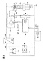
図2は本発明の概略図を表す。一体型整流ブリッジ10を備える車載のオルタネーター9およびバッテリ11によって公称14ボルトの車両電気系統電圧が発生され、DC−DCコンバータ12によって14ボルト超の電圧に昇圧され、変圧器に印加される。この変圧器は一次巻線L1と二次巻線L2とを備えた点火用変圧器8の形態にあり、ダイオードD1及びパワー半導体13を介して接地するようになっている。点火用変圧器の二次巻き線L2は、スイッチオンの状態にある制限ダイオードD2を介してスパークプラグ5の電極に接続している。スパークプラグおよび点火用変圧器は、例示された実施形態では一体型のロッド型点火用変圧器として示される。これは、本発明の有利な設計の変形である。その次に有利な本発明の実施形態では、点火用変圧器とスパークプラグを、別々に構成して電気線を介して互いに接続された構成部品として設計することもできる。点火用変圧器の一次側巻線L1は、その一方の端部で車両電気系統電圧の正の電圧線に接続され、第2端部で半導体パワーステージに接続され、さらに測定抵抗器Rの形態にある電流センサを介して車両電気系統の接地線に接続される。
FIG. 2 represents a schematic diagram of the present invention. A vehicle electric system voltage having a nominal voltage of 14 volts is generated by an in-vehicle alternator 9 including an integrated
半導体パワーステージ13は、点火制御ユニット14によって作動される。点火制御ユニット、半導体パワーステージおよび電流センサは、本発明の1つの可能な例示的実施形態では別々に形成される。本発明はこの実施形態に制限されることはない。使用される電流センサは、一次コイルの電流を測定するクリップオン型の電流計であってもよい。パワーステージは必ずしも半導体パワーステージの形態である必要はない。点火制御ユニットとエンジン制御ユニットMEとの間の分離は、より理論的なものであり、実際上は種々条件に応じて決まる。特に、点火制御ユニットおよびエンジン制御ユニットは、一体型の装置として構成してもよい。しかしながら、図5と併せてさらに説明されるように、集積回路としてロッド型点火用変圧器内に一体化された一体化点火エレクトロニクスが好ましい。
The
図2のように本発明による点火装置の機能および作動が、図4のタイミング図と併せて以下に続く文章でさらに詳細に説明される。上位のエンジン制御ユニットMEが、信号Z1を点火時間ウィンドウ用の識別子として点火エレクトロニクスの制御ユニット14に送信する。点火用変圧器8の充電が、点火時間ウィンドウ用の信号Z1によってトリガされる。充電は、パワー出力ステージ13内の、点火エレクトロニクスの制御ユニットによってクロックされるスイッチイング素子Q1によって一次コイルL1とダイオードD1とを介して、フライバックコンバーター原理に従い実行される。簡潔にするため、図4におけるクロック信号には同じくQ1が割り当てられる。スイッチイング素子は、好ましくは半導体スイッチ、特にMOS FETあるいはIGBTである。その接続された位置(on)において、一次コイルL1は導電性をもって接地される。一次電流Ipが、最大値Ipmaxに上昇する。最大一次電流に達すると、エネルギーはもはや点火用変圧器に蓄積されない。点火用変圧器は、その2個のコイル、それらの伝達比、およびまたそれらの連結要素によって、接続されたスパークプラグの電極対に適合しなければならない。点火用変圧器のエネルギー量および2個のコイルの伝達比は、いずれの場合も、スパーク放電および適切なスパークの燃焼時間のための放電電圧に達するのに十分なものでなければならない。DCコンバータ12を通る供給電圧が既知のものである場合および点火用変圧器のコイル定数が既知のものである場合、原理上、一次電流が最大に達するまでの時間を計算することができる。さらに、充電時間も測定によって実験的に決定することができる。すなわち、スイッチイング素子Q1をクロックすることによる純粋な時間制御設定機能を用いて、スパークプラグの電極におけるスパーク放電を達成することが可能であり、いずれの場合も最大一次電流Ipmaxに達するためのスイッチオン時間tonのあと、予め決められた時間toffの間スイッチイング素子をスイッチオフすることによる。
The function and operation of the ignition device according to the present invention as in FIG. The host engine control unit ME sends the signal Z1 to the ignition electronics control unit 14 as an identifier for the ignition time window. Charging of the ignition transformer 8 is triggered by a signal Z1 for the ignition time window. Charging is carried out according to the flyback converter principle via the primary coil L1 and the diode D1 by the switching element Q1 clocked by the ignition electronics control unit in the
時間toffの間、点火用変圧器の二次コイルの電流Isは低下する。従って、時間toffは、点火電圧が過度に低くなることを排除することによって、スパークが消滅する危険性がなくなるように十分に短く選択される。 During the time toff, the secondary coil current Is of the ignition transformer decreases. Accordingly, the time toff is selected to be sufficiently short so that there is no risk of the spark disappearing by eliminating the ignition voltage becoming too low.
より複雑な作動構成では、スイッチイング素子Q1をクロックするスイッチング時間を最適化することができる。このため、たとえば一次電流の測定を用いて、再充電プロセスを最適化することができる。一次コイルに残って蓄積されているエネルギー量は、再充電プロセスに特に重要である。そしてこれは、スパークによって消費されたエネルギーに応じて決まり、その消費されたエネルギーは、燃焼室内の温度、圧力、湿気などの条件に応じて決まる。消費されたエネルギーは、特に、スパーク放電が最初の試みで仮にも発生したかどうかに応じて決定的に決まる。ごく僅かなエネルギーが点火用変圧器から引かれた場合、再充電作業は、完全な充電ほど長く続かない。しかしながら、スパーク放電を達成するための純粋な時間制御設定機能を用いると、一次電流が、点火が再び始まり得るその最大値に再び到達した、その起点となった最も早い時間を、再充電作業のために決定することは不可能である。従って、一次電流用の別の最大電流監視を追加すること、および従ってスイッチイング素子をスイッチオフする時期をトリガすること、従って最大一次電流に到達する時期における点火時期をトリガすることが有利である。従って、再充電作業は、点火用変圧器内の残留エネルギー含量に最適に適合することができ、これにより再充電時間が短縮化され、従って時間ウィンドウ内でより多くの再点火作業が可能になる。 In more complex operating configurations, the switching time for clocking the switching element Q1 can be optimized. Thus, the recharging process can be optimized using, for example, primary current measurements. The amount of energy remaining in the primary coil and stored is particularly important for the recharging process. This is determined according to the energy consumed by the spark, and the consumed energy is determined according to conditions such as temperature, pressure, and humidity in the combustion chamber. The energy consumed depends in particular on whether or not a spark discharge has occurred in the first attempt. If very little energy is drawn from the ignition transformer, the recharge operation will not last as long as a full charge. However, with a pure time control setting function to achieve spark discharge, the earliest time at which the primary current has regained its maximum value at which ignition can begin again can be re-established. It is impossible to make a decision. It is therefore advantageous to add another maximum current monitor for the primary current and thus trigger when to switch off the switching element and thus trigger the ignition timing at the time when the maximum primary current is reached. . Thus, the recharging operation can be optimally adapted to the residual energy content in the ignition transformer, thereby reducing the recharging time and thus allowing more reignition operations within the time window. .
最も好ましい実施形態では、二次電流の測定あるいはイオン電流の測定が、スパークプラグの電極で行なわれ、結果として、点火スパークがなおも燃焼しているかどうかを判断することも可能である。点火スパークが時期尚早に消滅した場合、これは二次電流の測定によって検出することができ、時間制御設定機能の時間toffが始まる前であっても、点火用変圧器の再充電がすぐに開始されることができる。 In the most preferred embodiment, secondary current measurements or ionic current measurements are made at the electrodes of the spark plug, so that it is possible to determine whether the ignition spark is still burning. If the ignition spark is prematurely extinguished, this can be detected by measuring the secondary current, and the recharging of the ignition transformer starts immediately even before the time toff of the time control setting function starts. Can be done.
図4の最下部タイミング図において、点火エレクトロニクスによる作動の結果としての、スパークプラグの電極における電圧プロファイルが、完全を目的として例により示される。スイッチイング素子Q1が誘導パルスによってスイッチオフされたとき、スパーク放電を達成するための最大点火電圧Umaxが常に得られる。誘導パルスはその後活動状態になる。この場合、この最大点火電圧Umaxは点火時間ウィンドウ内において複数回到達される。図2で示される例示的な実施形態の場合、それは3回である。 In the bottom timing diagram of FIG. 4, the voltage profile at the electrode of the spark plug as a result of actuation by ignition electronics is shown by way of example for completeness. When the switching element Q1 is switched off by the induction pulse, the maximum ignition voltage Umax for achieving spark discharge is always obtained. The induction pulse then becomes active. In this case, the maximum ignition voltage Umax is reached a plurality of times within the ignition time window. For the exemplary embodiment shown in FIG. 2, it is three times.
図2に関して説明した中で既に言及しているように、本発明を実行するためのいくつかの発展形態がある。本発明による点火装置の、より高次に一体化された実施形態が図5に示される。さらに、車載の車両電気系統電圧が、昇圧制御器によって14ボルト超の電圧レベルまで大幅に上げられ、その電圧は、ロッド型点火用変圧器の一次側に供給される。しかし、点火制御のための分散された機能は、図2の実施形態よりも高次に一体化される。ロッド型点火用変圧器を充電させる機能およびスパーク放電を達成するための機能が、好ましくは集積回路IC内に組み合わされ、ロッド型点火用変圧器のハウジング内に一体化される。これらは主としてパワー出力ステージであり、スイッチイング素子Q1およびフライバックコンバータダイオードD1を備え、またパワー出力ステージの作動論理も備えている。集積回路は、バスシステムのデータラインを介する信号、あるいはシリアルデータラインを介する信号を用いて作動される。点火エレクトロニクスの集積回路は、これらのデータラインを介して通信可能となるようにエンジン制御ユニットMEに接続される。 As already mentioned in the description with respect to FIG. 2, there are several developments for carrying out the present invention. A higher integrated embodiment of the ignition device according to the present invention is shown in FIG. Furthermore, the on-vehicle vehicle electrical system voltage is significantly raised to a voltage level of more than 14 volts by the boost controller, and the voltage is supplied to the primary side of the rod-type ignition transformer. However, the distributed functions for ignition control are integrated higher than in the embodiment of FIG. The functions of charging the rod ignition transformer and achieving the spark discharge are preferably combined in the integrated circuit IC and integrated into the housing of the rod ignition transformer. These are mainly power output stages, which comprise a switching element Q1 and a flyback converter diode D1, and also the operating logic of the power output stage. The integrated circuit is operated using a signal via the data line of the bus system or a signal via the serial data line. The integrated circuit of the ignition electronics is connected to the engine control unit ME so as to be able to communicate via these data lines.
点火を作動させる方法に関しては、これによって大幅に柔軟な実行が許容される。集積回路とエンジン制御ユニットとの両方が、アプリケーションプログラムの形態でそれら自身の知能を有し、そのアプリケーションプログラムはそれぞれ、集積回路のマイクロプロセッサと、第一の正確さをもってエンジン制御ユニットとに、実行可能な形態で実装されている。これにより、アプリケーションプログラムを手段として、制御機能の分散を、従って良好な点火を達成させるための方法ステップの分散を、アプリケーションプログラムをプログラミングすることによって、いずれの場合においても適用可能なハードウェアの状態に最適に適合させることができる。従って、図5の点火装置は、図4と併せて既に説明された点火方法と、図3と併せて説明される点火方法との両方を実行するために用いることができる。 With respect to the way the ignition is activated, this allows a much more flexible implementation. Both the integrated circuit and the engine control unit have their own intelligence in the form of application programs, each of which executes to the integrated circuit microprocessor and to the engine control unit with first accuracy. It is implemented in a possible form. This allows the application program to be used as a means of distributing the control functions and thus the distribution of the method steps to achieve a good ignition by programming the application program in any case. Can be optimally adapted to. Accordingly, the ignition device of FIG. 5 can be used to perform both the ignition method already described in conjunction with FIG. 4 and the ignition method described in conjunction with FIG.
図3のタイミングシーケンスに従う点火方法は、点火時間ウィンドウ用の信号Z1および、パワー出力ステージの出力においてスイッチイング素子をクロックするためのQ1の2つの信号の組み合わせが主な要因となって図4の点火方法と異なる。従って図3の方法によれば、信号Z1は点火時間ウィンドウについての情報と、スパークプラグの点火と点火用変圧器の再充電とに関する情報との両方を含んでいる。この場合、たとえば、ロッド型点火用変圧器の一次巻線の接地電流経路が接続されている集積回路ICのスイッチイング素子に制御信号が印加される。信号自体は、好ましくは集積回路内で生成される。点火時間ウィンドウの開始および終了、また点火用変圧器の充電後、スパーク放電を発生させるためのスイッチオフ時期toffの配置など、信号の構成に関する情報が、好ましくはエンジン制御ユニット内で決定され、コード化された形態で、エンジン制御ユニットと集積回路との間のデータラインを介して、さらなる処理のために前記集積回路に送信される。点火時間ウィンドウ、点火コイルの充電、およびスパーク放電の点火に関する信号を1つの信号に組み合わせることによって、もしそうでない場合は個々の信号を互いに調整するために必要とされる費用が削減される。 The ignition method according to the timing sequence of FIG. 3 is mainly due to the combination of the signal Z1 for the ignition time window and the two signals Q1 for clocking the switching element at the output of the power output stage. Different from ignition method. Thus, according to the method of FIG. 3, the signal Z1 contains both information about the ignition time window and information about ignition of the spark plug and recharging of the ignition transformer. In this case, for example, the control signal is applied to the switching element of the integrated circuit IC to which the ground current path of the primary winding of the rod-type ignition transformer is connected. The signal itself is preferably generated within the integrated circuit. Information regarding the configuration of the signal, such as the start and end of the ignition time window and the arrangement of the switch-off time toff for generating a spark discharge after charging the ignition transformer, is preferably determined in the engine control unit Is sent to the integrated circuit for further processing via a data line between the engine control unit and the integrated circuit. By combining the ignition time window, ignition coil charge, and spark discharge ignition signals into one signal, the cost required to adjust the individual signals to each other otherwise is reduced.
Claims (17)
前記電圧源の出力電圧が、DCコンバータ(12)によって昇圧されて前記点火用変圧器の前記一次巻線に印加され、
前記スイッチイング素子が、前記制御ユニット(ME、13)にあらかじめ組み込まれた時間制御設定機能に従って、点火時間ウィンドウ内で複数回、スイッチオンおよびスイッチオフすることを特徴とする点火装置。 At least one voltage source, at least one ignition transformer (8), at least one spark plug (5), and at least one control unit (ME, 13), the control unit comprising the ignition transformer The ignition device for an internal combustion engine in which the ignition transformer is charged and discharged a plurality of times within the ignition time window by connecting the primary winding (L1) to the ground path by the switching element (Q1) In
The output voltage of the voltage source is boosted by a DC converter (12) and applied to the primary winding of the ignition transformer,
Ignition device characterized in that the switching element switches on and off several times within an ignition time window according to a time control setting function incorporated in advance in the control unit (ME, 13).
最初のスパーク放電が、前記一次電流(Ip)の遮断によってスパークプラグ(5)において発生され、
前記点火コイルが、前記最初のスパーク放電のあと、再供給される前記一次電流(Ip)によって再充電される、内燃機関用の点火方法において、
前記電圧源の出力電圧が、DCコンバータによって14ボルトよりも高い電圧レベルまで昇圧され、
前記一次電流(Ip)用の予め規定された放電時間(toff)で、時間制御設定機能によって前記スパーク放電が制御されることを特徴とする点火方法。 The ignition coil is charged by the primary current (Ip) supplied from the voltage source via the primary winding (L1) of the ignition coil (8),
An initial spark discharge is generated in the spark plug (5) by the interruption of the primary current (Ip),
In the ignition method for an internal combustion engine, the ignition coil is recharged by the primary current (Ip) resupplied after the first spark discharge.
The output voltage of the voltage source is boosted to a voltage level higher than 14 volts by a DC converter;
An ignition method, wherein the spark discharge is controlled by a time control setting function at a predetermined discharge time (toff) for the primary current (Ip).
Applications Claiming Priority (2)
| Application Number | Priority Date | Filing Date | Title |
|---|---|---|---|
| DE102004056844A DE102004056844A1 (en) | 2004-11-25 | 2004-11-25 | Fast multiple spark ignition |
| PCT/EP2005/012144 WO2006056329A1 (en) | 2004-11-25 | 2005-11-12 | Rapid multiple spark ignition |
Publications (1)
| Publication Number | Publication Date |
|---|---|
| JP2008522066A true JP2008522066A (en) | 2008-06-26 |
Family
ID=35520778
Family Applications (1)
| Application Number | Title | Priority Date | Filing Date |
|---|---|---|---|
| JP2007541759A Abandoned JP2008522066A (en) | 2004-11-25 | 2005-11-12 | Fast multi-spark ignition |
Country Status (5)
| Country | Link |
|---|---|
| US (1) | US20080121214A1 (en) |
| EP (1) | EP1815131A1 (en) |
| JP (1) | JP2008522066A (en) |
| DE (1) | DE102004056844A1 (en) |
| WO (1) | WO2006056329A1 (en) |
Cited By (4)
| Publication number | Priority date | Publication date | Assignee | Title |
|---|---|---|---|---|
| KR20130132877A (en) * | 2010-11-23 | 2013-12-05 | 콘티넨탈 오토모티브 게엠베하 | Method for operating an ignition device for an internal combustion engine and ignition device for an internal combustion engine for carrying out the method |
| KR20160068918A (en) * | 2013-10-11 | 2016-06-15 | 로베르트 보쉬 게엠베하 | Method for operating a load connected to a motor vehicle electrical system |
| KR101778010B1 (en) | 2009-12-11 | 2017-09-13 | 콘티넨탈 오토모티브 게엠베하 | Method for operating an ignition device for an internal combustion engine, and ignition device for an internal combustion engine for carrying out the method |
| KR101850913B1 (en) | 2013-04-11 | 2018-04-20 | 가부시키가이샤 덴소 | Ignition control device |
Families Citing this family (14)
| Publication number | Priority date | Publication date | Assignee | Title |
|---|---|---|---|---|
| JP4640282B2 (en) * | 2006-01-31 | 2011-03-02 | 株式会社デンソー | Ignition control device for internal combustion engine |
| FR2904155B1 (en) * | 2006-07-21 | 2011-12-23 | Peugeot Citroen Automobiles Sa | IGNITION SYSTEM AND INTERNAL COMBUSTION ENGINE HAVING SUCH AN IGNITION SYSTEM |
| JP2008088947A (en) * | 2006-10-04 | 2008-04-17 | Toyota Motor Corp | Ignition control device for engine |
| JP4803008B2 (en) * | 2006-12-05 | 2011-10-26 | 株式会社デンソー | Ignition control device for internal combustion engine |
| PL2119906T3 (en) * | 2008-05-14 | 2011-07-29 | Delphi Tech Inc | Method of providing multicharge ignition |
| DE102008039729B4 (en) * | 2008-08-26 | 2020-07-30 | Bayerische Motoren Werke Aktiengesellschaft | Device for controlling an ignition process in an internal combustion engine |
| US8931457B2 (en) | 2009-08-18 | 2015-01-13 | Woodward, Inc. | Multiplexing drive circuit for an AC ignition system with current mode control and fault tolerance detection |
| US8276564B2 (en) * | 2009-08-18 | 2012-10-02 | Woodward, Inc. | Multiplexing drive circuit for an AC ignition system |
| DE102010015344B4 (en) * | 2010-04-17 | 2013-07-25 | Borgwarner Beru Systems Gmbh | A method for igniting a fuel-air mixture of a combustion chamber, in particular in an internal combustion engine by generating a corona discharge |
| DE102010045689A1 (en) * | 2010-09-16 | 2011-04-21 | Daimler Ag | Method for operating internal combustion engine of passenger car, involves accomplishing measure for compensation of deviation, and adjusting quantity of fuel for compensating deviation, where measure affects combustion in cylinder |
| KR20130121887A (en) * | 2010-11-23 | 2013-11-06 | 콘티넨탈 오토모티브 게엠베하 | Ignition device for an internal combustion engine and method for operating an ignition device for an internal combustion engine |
| DE102012105797A1 (en) * | 2011-07-01 | 2013-01-03 | Woodward, Inc. | Alternating current (AC) ignition device for internal combustion engine, has comparator network which compares ignition system voltage and reference voltage and indicates compared result to controller to operate switching network |
| DE102011089966B4 (en) * | 2011-12-27 | 2015-05-21 | Continental Automotive Gmbh | Method for operating an ignition device for an internal combustion engine |
| JP5474120B2 (en) * | 2012-04-09 | 2014-04-16 | 三菱電機株式会社 | Ignition device and ignition method for internal combustion engine |
Family Cites Families (15)
| Publication number | Priority date | Publication date | Assignee | Title |
|---|---|---|---|---|
| US4829973A (en) * | 1987-12-15 | 1989-05-16 | Sundstrand Corp. | Constant spark energy, inductive discharge ignition system |
| US5842456A (en) * | 1995-01-30 | 1998-12-01 | Chrysler Corporation | Programmed multi-firing and duty cycling for a coil-on-plug ignition system with knock detection |
| DE19524539C1 (en) * | 1995-07-05 | 1996-11-28 | Telefunken Microelectron | Circuit arrangement for ion current measurement in the combustion chamber of an internal combustion engine |
| ES2153175T3 (en) * | 1997-06-02 | 2001-02-16 | Federal Mogul Ignition Spa | IGNITION SYSTEM FOR MULTIPLE SPARKS. |
| DE19829583C1 (en) * | 1998-07-02 | 1999-10-07 | Daimler Chrysler Ag | Breakthrough voltage determining method for AC ignition system diagnosis in IC engine |
| DE19849258A1 (en) * | 1998-10-26 | 2000-04-27 | Bosch Gmbh Robert | Energy regulation of internal combustion engine ignition system with primary side short circuit switch involves controlling closure time/angle depending on shorting phase primary current |
| US6378513B1 (en) * | 1999-07-22 | 2002-04-30 | Delphi Technologies, Inc. | Multicharge ignition system having secondary current feedback to trigger start of recharge event |
| JP3482161B2 (en) * | 1999-08-03 | 2003-12-22 | 株式会社日立製作所 | Ignition system for internal combustion engine |
| US6694959B1 (en) * | 1999-11-19 | 2004-02-24 | Denso Corporation | Ignition and injection control system for internal combustion engine |
| US6367318B1 (en) * | 2000-03-20 | 2002-04-09 | Delphi Technologies, Inc. | Multicharge ignition system having combustion feedback for termination |
| DE10062892A1 (en) * | 2000-12-16 | 2002-07-11 | Bosch Gmbh Robert | Ignition device for multi-cylinder internal combustion engine, has spark plug switched to external fixed voltage to increase flow duration of secondary current |
| JP2002364509A (en) * | 2001-04-05 | 2002-12-18 | Nippon Soken Inc | Knock detector for internal combustion engine |
| DE10121993B4 (en) * | 2001-05-05 | 2004-08-05 | Daimlerchrysler Ag | Ignition system for internal combustion engines |
| US6701896B2 (en) * | 2001-11-13 | 2004-03-09 | Prufrex-Elektro-Apparatebau, Inh. Helga Müller, geb. Dutschke | Microelectronic ignition method and ignition module with ignition spark burn-time prolonging for an internal combustion engine |
| US7124019B2 (en) * | 2004-08-06 | 2006-10-17 | Ford Global Technologies, Llc | Powertrain control module spark duration diagnostic system |
-
2004
- 2004-11-25 DE DE102004056844A patent/DE102004056844A1/en not_active Withdrawn
-
2005
- 2005-11-12 US US11/791,536 patent/US20080121214A1/en not_active Abandoned
- 2005-11-12 WO PCT/EP2005/012144 patent/WO2006056329A1/en active Application Filing
- 2005-11-12 EP EP05803688A patent/EP1815131A1/en not_active Withdrawn
- 2005-11-12 JP JP2007541759A patent/JP2008522066A/en not_active Abandoned
Cited By (6)
| Publication number | Priority date | Publication date | Assignee | Title |
|---|---|---|---|---|
| KR101778010B1 (en) | 2009-12-11 | 2017-09-13 | 콘티넨탈 오토모티브 게엠베하 | Method for operating an ignition device for an internal combustion engine, and ignition device for an internal combustion engine for carrying out the method |
| KR20130132877A (en) * | 2010-11-23 | 2013-12-05 | 콘티넨탈 오토모티브 게엠베하 | Method for operating an ignition device for an internal combustion engine and ignition device for an internal combustion engine for carrying out the method |
| KR101856036B1 (en) * | 2010-11-23 | 2018-06-20 | 콘티넨탈 오토모티브 게엠베하 | Method for operating an ignition device for an internal combustion engine and ignition device for an internal combustion engine for carrying out the method |
| KR101850913B1 (en) | 2013-04-11 | 2018-04-20 | 가부시키가이샤 덴소 | Ignition control device |
| KR20160068918A (en) * | 2013-10-11 | 2016-06-15 | 로베르트 보쉬 게엠베하 | Method for operating a load connected to a motor vehicle electrical system |
| KR102469591B1 (en) * | 2013-10-11 | 2022-11-22 | 로베르트 보쉬 게엠베하 | Method for operating a load connected to a motor vehicle electrical system |
Also Published As
| Publication number | Publication date |
|---|---|
| US20080121214A1 (en) | 2008-05-29 |
| DE102004056844A1 (en) | 2006-06-01 |
| EP1815131A1 (en) | 2007-08-08 |
| WO2006056329A1 (en) | 2006-06-01 |
Similar Documents
| Publication | Publication Date | Title |
|---|---|---|
| JP2008522066A (en) | Fast multi-spark ignition | |
| US8813732B2 (en) | Internal combustion engine control system | |
| EP2325476B1 (en) | Coupled multi-charge ignition system with an intelligent controlling circuit | |
| US7392798B2 (en) | Multiple-spark ignition system for internal combustion engine | |
| US6779517B2 (en) | Ignition device for internal combustion engine | |
| JP6269271B2 (en) | Ignition device for internal combustion engine | |
| CN101922396B (en) | Method for operating a multi-spark ignition system, and multi-spark ignition system | |
| US10422310B2 (en) | Ignition device | |
| US6666195B2 (en) | Method for producing a sequence of high-voltage ignition sparks and high-voltage ignition device | |
| US20170096979A1 (en) | Ignition device controlling streamer discharge and arc discharge | |
| EP3130792B1 (en) | Ignition device for internal combustion engine | |
| EP2876298A1 (en) | Method and apparatus to control an ignition system with two coils for one spark plug | |
| JP4952641B2 (en) | Ignition system for internal combustion engine | |
| EP3130793B1 (en) | Ignition device for internal combustion engine | |
| JP6337584B2 (en) | Ignition device | |
| JP6349895B2 (en) | Ignition device for internal combustion engine | |
| US10138861B2 (en) | Ignition device | |
| EP0811763B1 (en) | Ignition system with generator voltage distribution control | |
| KR20230016464A (en) | System for predicting wear amount of spark plug and method thereof | |
| JP4352223B2 (en) | Ignition system for capacitor discharge internal combustion engine | |
| US9212645B2 (en) | Internal combustion engine ignition device | |
| JP2007198220A (en) | Non-contact ignition device of internal combustion engine | |
| JPH0565864A (en) | Combustion condition detecting device for gasoline engine | |
| CN113748265A (en) | Electronic device for controlling ignition coil of internal combustion engine and electronic ignition system for detecting fire of internal combustion engine | |
| CN113710890A (en) | Electronic device for controlling ignition coil of internal combustion engine and electronic ignition system for detecting pre-ignition of internal combustion engine |
Legal Events
| Date | Code | Title | Description |
|---|---|---|---|
| A621 | Written request for application examination |
Free format text: JAPANESE INTERMEDIATE CODE: A621 Effective date: 20080624 |
|
| A762 | Written abandonment of application |
Free format text: JAPANESE INTERMEDIATE CODE: A762 Effective date: 20091028 |