JP4351394B2 - Non-linear and linear methods for enlarging or reducing image resolution conversion - Google Patents
Non-linear and linear methods for enlarging or reducing image resolution conversion Download PDFInfo
- Publication number
- JP4351394B2 JP4351394B2 JP2000597749A JP2000597749A JP4351394B2 JP 4351394 B2 JP4351394 B2 JP 4351394B2 JP 2000597749 A JP2000597749 A JP 2000597749A JP 2000597749 A JP2000597749 A JP 2000597749A JP 4351394 B2 JP4351394 B2 JP 4351394B2
- Authority
- JP
- Japan
- Prior art keywords
- grid
- image
- output
- input image
- linear
- Prior art date
- Legal status (The legal status is an assumption and is not a legal conclusion. Google has not performed a legal analysis and makes no representation as to the accuracy of the status listed.)
- Expired - Lifetime
Links
- 230000009021 linear effect Effects 0.000 title claims abstract description 174
- 238000006243 chemical reaction Methods 0.000 title claims abstract description 127
- 238000000034 method Methods 0.000 title claims abstract description 96
- 239000013598 vector Substances 0.000 claims abstract description 31
- 238000004364 calculation method Methods 0.000 abstract description 14
- 238000013341 scale-up Methods 0.000 abstract description 4
- 230000009467 reduction Effects 0.000 description 68
- 238000010586 diagram Methods 0.000 description 11
- 230000009466 transformation Effects 0.000 description 8
- 230000009022 nonlinear effect Effects 0.000 description 4
- 230000008859 change Effects 0.000 description 3
- 238000012545 processing Methods 0.000 description 3
- 238000012986 modification Methods 0.000 description 2
- 230000004048 modification Effects 0.000 description 2
- 230000009286 beneficial effect Effects 0.000 description 1
- 230000015572 biosynthetic process Effects 0.000 description 1
- 238000000205 computational method Methods 0.000 description 1
- 238000009792 diffusion process Methods 0.000 description 1
- 238000013507 mapping Methods 0.000 description 1
- 230000007246 mechanism Effects 0.000 description 1
- 238000005192 partition Methods 0.000 description 1
- 230000008569 process Effects 0.000 description 1
- 230000004044 response Effects 0.000 description 1
- 238000005070 sampling Methods 0.000 description 1
- 238000010561 standard procedure Methods 0.000 description 1
- 238000000844 transformation Methods 0.000 description 1
Images
Classifications
-
- G—PHYSICS
- G06—COMPUTING; CALCULATING OR COUNTING
- G06T—IMAGE DATA PROCESSING OR GENERATION, IN GENERAL
- G06T3/00—Geometric image transformations in the plane of the image
- G06T3/40—Scaling of whole images or parts thereof, e.g. expanding or contracting
- G06T3/4007—Scaling of whole images or parts thereof, e.g. expanding or contracting based on interpolation, e.g. bilinear interpolation
-
- G—PHYSICS
- G06—COMPUTING; CALCULATING OR COUNTING
- G06T—IMAGE DATA PROCESSING OR GENERATION, IN GENERAL
- G06T3/00—Geometric image transformations in the plane of the image
- G06T3/04—Context-preserving transformations, e.g. by using an importance map
- G06T3/047—Fisheye or wide-angle transformations
Landscapes
- Physics & Mathematics (AREA)
- General Physics & Mathematics (AREA)
- Engineering & Computer Science (AREA)
- Theoretical Computer Science (AREA)
- Editing Of Facsimile Originals (AREA)
- Image Processing (AREA)
- Ultra Sonic Daignosis Equipment (AREA)
- Studio Circuits (AREA)
- Photoreceptors In Electrophotography (AREA)
- Liquid Crystal (AREA)
- Controls And Circuits For Display Device (AREA)
Abstract
Description
【0001】
(発明の分野および背景)
本発明はディジタル画像処理に関するものである。特に、本発明は、ディジタル入力画像の解像度を規定出力ウィンドウのために拡大あるいは縮小する非線形および線形方法に関するものである。
ディジタルディスプレイは、その走査速度およびピクセル解像度によって特徴付けられる。標準非インタレースディスプレイは、少なくとも60HZの走査速度および各ラインで少なくとも480ライン(行)×640ピクセル(列)の解像度を有する。各々が異なる解像度および走査速度を有する非インタレースディスプレイは、一般的には、VGA、SVGA、XGA、SXGAおよびUGAとしてフォーマット化される。様々なディスプレイシステムは一緒に混合され、一方の解像度から他方の解像度への変換が必要とされることがしばしば生じる。例えば、デインタレースビデオ画像は、通常サイズが480ライン×640ピクセル解像度(VGAフォーマット)のものである。このような画像は、1200ライン×1600ピクセルのピクセル解像度性能を有するモニタ上に表示される場合、比較的小さく可視化される。ビデオ画像とは異なる解像度を有するディスプレイモニタの全解像度性能以上でビデオ画像を表示するためにディジタル入力解像度を規定出力ウィンドウのために拡大あるいは縮小する方法に対する要求がある。
最新のインタレースあるいは非インタレースのビデオスクリーンの最も重要な特徴の1つは、ディスプレイスクリーンのアスペクト比と普通呼ばれている実際の表示領域の幅(列数)と高さ(行数)との比である。現在は、最も一般に普及しているアスペクト比は4:3(例えば、サイズが480行×640列あるいはピクセル、または1200行×1600列のデインタレースビデオ画像(VGAフォーマット))である。16:9あるいは21:9のようなアスペクト比を有する新しいスクリーンは、現在市場で入手可能である。高精細度テレビスクリーンは、一般的には16:9のアスペクト比を有する。異なるアスペクト比、例えば16:9を有するディスプレイ上に1つのアスペクト比、例えば4:3の画像を表示するために、アスペクト比間で画像を変換する非常に複雑な変換が必要とされる。
【0002】
入出力変換比が1:1でない、例えば16:9に等しくない4:3であるこのような非線形解像度変換の場合では、ディジタル入力画像の標準線形解像度変換方法を使用することは対応する出力画像内に歪みを生じる。その大部分が、変換出力画像を発生するために入力画像において欠けているピクセルの値を推定するかあるいは既知の値を有するピクセルを削除するかのいずれかによってピクセルを加算する目的のために線形補間処理を特徴とするかあるいは含むかのいずれかであるビデオ画像解像度変換およびスケーリングの様々な方法が、非線形あるいは線形の場合に対して開発された。拡大解像度変換中出力画像を形成する一部として欠けているピクセルを入力画像に付加するかあるいは縮小解像度変換中出力画像を形成する一部としてピクセルを入力画像から削除する標準補間法を使用することは、それぞれ画像解像度変換が拡大であろうが縮小であろうがかに従って最初の入力画像に付加ピクセルを含むかあるいは削除ピクセルを最初の入力画像から省くかのいずれかである出力画像を生じる。このような方法では、入力画像データは単に出力画像を形成するテンプレートとして使用される。画像解像度変換のより精巧な方法および比較的高品質の結果が得られる方法は、各出力画像ピクセルを、原則として解像度変換の開始点としてのみ入力画像ピクセルを使用するスクラッチから計算することによって全く新しい出力画像の形成を含む方法であり、入力画像データの全部あるいは一部が単に出力画像の一部になる場合ではない。さらに、多数の標準線形補間法は、高品質解像度変換画像を発生するのに計算に関して有効でなくてもよい。
したがって、ディスプレイスクリーンアスペクト比の非線形変化を有する拡大あるいは縮小解像度変換から生じる歪みを最少にする精巧で、さらに計算に関して有効で、非線形な変換に対する要求がある。ビデオ入力画像とディスプレイ出力画像との間のアスペクト比の変化が全然ない場合、拡大あるいは縮小の画像解像度変換を実行する精巧で、さらに計算に関して有効な線形変換に対する要求もあり、この有効な線形変換を有することは有益である。
【0003】
画像解像度変換の公知の方法の相対的な適否は最終的には生じる画質によって決まる。さらに、異なる画像解像度変換の方法は異なる条件の下ではさらによく機能する。
Berladのために発行された米国特許第5,513,120号は、ビデオ画像の変換のために必要とされる欠けているピクセルを推定するために、補間データを必要とするグリッド位置点と一直線になっている最も接近している隣接グリッド点および次の最も接近している隣接グリッド点を使用する4点線形補間方法に基づいている。補間は、4つの補間係数および各出力ピクセル値の決定のためのラグランジュ多項式の使用を必要とし、それによって画像のテクスチュアはピクセル位置の関数として変動しない。補間方法はn次元ディスプレイグリッドまで拡張できる。
Malinowskiらのために発行された米国特許第5,574,572号は、線形補間を特徴とし、ビデオ画像の水平あるいは垂直のスケーリングのために一定の係数を有するFIRフィルタを分割するビデオスケーリング方法および装置の様々な形態を示している。
【0004】
Lumelskyらのために発行された米国特許第5,119,082号は、ウィンドウを全ディスプレイのサブセットとして規定し、適合するビデオ画像をスケーリングする手段とともにビデオ拡大のための線形スケーリング方法によってピクセルレート拡大回路を特徴とする。この回路は、選択される隣接走査ラインが入力画像を垂直方向あるいは水平方向に拡大するためにフレームバッファから読み出されるときに選択される隣接走査ラインを繰り返させる線形スケーリング機構を含む。
Greggainらのために発行される米国特許第5,559,905号は、補間フィルタの線形組み合わせで作動するディジタル画像リサイジング装置を記載している。フィルタ係数は、入力データと乗算され、結果はシフトされ、符号は画像をリサイジングする減少された精度を補償するように拡大される。
Wongらのために発行された米国特許第5,796,879号は、画像補間を実行する領域に基づく補間の技術を使用し、画像の拡大を強調することを教示している。ピクセル値は、入力画像のサンプリングサイズに比例する領域に対する曲線の積分から決定される。線形フィルタの使用および線形多項式を解くことによる係数の数値計算を含む2つの積分器および2つの補間ステップは、所望の画像変換を行うために必要である。
【0005】
佐野のために発行された米国特許第5,532,716号は、縮小画像のための解像度変換システムを示している。このシステムは、入出力画像サイズに比例するスケーリングファクタで作動し、水平方向および垂直方向の両方に線形画像変換を行う。
山下らのために発行された米国特許第5,446,831号は、画像を縮小する画像データプロセッサを記載している。2を底とする対数式は所望の解像度変換を実行するのに必要であるデータ量を変えるために使用される。画像プロセッサは、2進画像データを変換し、垂直方向および水平方向の両方に減少させる。
エラー拡散技術を使用するディジタル画像解像度変換の付加的方法は、Eschbachのために発行された米国特許第5,208,871号を含み、ディジタル化入力画像の基準クラスタを使用する領域マッピング技術は、Loceらのために発行された米国特許第5,758,034号および米国特許第5,689,343号を含んでいる。
【0006】
(発明の開示)
本発明は、拡大あるいは縮小画像解像度変換の非線形および線形方法に関するものである。
本発明の非線形および線形の拡大あるいは縮小画像解像度変換の方法は、非線形あるいは線形ピクセル位置制御関数を使用することによって出力グリッドの画像ピクセルを入力グリッドの画像ピクセルに関連づける新しい、独特な方法を特徴とする。さらに、出力画像は、出力画像を形成するテンプレートとして入力画像ピクセルデータを使用する線形補間を特徴とする画像解像度変換の現標準方法とは著しく違って適切に入力画像ピクセルデータに関連している間、全く新しいセットの出力ピクセルデータを発生することによって形成される。
本発明の方法は、この方法が、非線形の拡大あるいは縮小画像解像度変換中入力画像のアスペクト比に等しい出力画像のアスペクト比を保持することを可能にし、等しくない出力画像および入力画像のアスペクト比を特徴とする。線形拡大あるいは縮小の画像解像度変換の場合、出力画像および入力画像のアスペクト比は同じである。本発明は、ビデオ画像の拡大あるいは縮小画像解像度変換の精巧で、さらに計算に関して有効な方法である。本発明の方法を使用する結果として生じる出力画像は、高画質であり、元の入力画像を厳密に示している。
【0007】
本発明の非線形および線形の拡大あるいは縮小の画像解像度変換の方法の好ましい実施例は下記の動作原理ステップを特徴とする。(1)入力画像およびその目標出力画像を特徴とする。(a)入出力画像グリッドを規定し、設定する。(b)入力画像のスケーリングモードを決定する。(c)非線形あるいは線形の画像解像度変換であるかどうかを決定する。(2)入力画像をFIRフィルタで畳み込む。(3)出力画像グリッドのピクセル位置を入力画像グリッドに関連づけるピクセル位置制御関数を規定する。位置制御関数を使用して接続グリッドを規定し、設定する。(4)ピクセル位置制御関数および接続グリッドを使用して入力画像グリッド内に埋め込まれた出力画像ピクセルの実位置座標を計算する。(5)接続グリッドに位置決めされた出力画像ピクセルの実位置を囲む入力画像グリッドの隣接ピクセルの位置座標を識別する。(6)接続グリッドに位置決めされた出力ピクセルの実位置座標と入力画像グリッドに位置決めされた隣接ピクセル位置座標との(デルタ)関数差を規定し、数値を求める。(7)接続グリッドに位置決めされた出力ピクセルの実位置を囲む入力画像グリッドの隣接ピクセルに値を割り当てる。(8)接続グリッドに位置決めされた出力ピクセルの実位置を囲む入力画像グリッドの隣接ピクセルの値から局所係数を規定し、計算する。(9)出力ピクセルの予備値を計算する。(10)最終値を計算し、出力ピクセルに割り当てる。(11)ステップ(1)〜(10)を繰り返すことによって値を計算し、次の出力ピクセルに割り当てる。(12)完了された解像度変換画像を表示する。
【0008】
本発明によれば、拡大、縮小、あるいは混合モードの拡大/縮小画像解像度変換の非線形および線形方法が提供され、この方法のステップは、データプロセッサで実行され、この方法は、以下のステップ(a)〜(h)を含む。(a)複数のピクセルを特徴とする入力画像であって、入力画像グリッドでプロットされ、入力画像グリッドが入力画像グリッド座標系を特徴とする、入力画像を受信するステップと、(b)ピクセル位置制御関数であって、接続グリッド座標系に対して接続グリッドを規定し、および設定し、それによってピクセル位置制御関数および接続グリッド座標系を有する接続グリッドの各々が、出力画像グリッド座標系を有する出力画像グリッドを入力画像グリッド座標系を有する入力画像グリッドに関連づける、ピクセル位置制御関数を提供するステップと、(c)出力画像グリッドに位置決めされた複数の出力ピクセル位置の各々の接続グリッドに位置決めされた実位置座標をピクセル位置制御関数から計算するステップと、(d)複数の出力ピクセル位置の各実位置座標を囲む入力画像グリッドに位置決めされた隣接ピクセルの位置座標を決定するステップと、(e)複数の出力ピクセル位置の各々の各実位置座標と入力画像グリッドに位置決めされた隣接ピクセルの位置座標との差を計算するステップと、(f)複数の出力ピクセル位置の各々に対して、新しい局所係数のセットを前記複数の出力ピクセル位置の各々の各実位置座標を囲む隣接ピクセルの既知値から計算するステップと、(g)出力画像グリッドに位置決めされた複数の出力ピクセルの各々に対する値を前記ピクセル、およびn2個の隣接ピクセルを特徴とする二次元画像に対する、2つのベクトル間の内部乗算を含み、2つのベクトルの第1のベクトルが、複数の出力ピクセル位置の各々の二次元の接続グリッド座標系に対して規定された各実位置座標と二次元の入力画像座標系に対して規定されたn2個の隣接ピクセルの位置座標との差の1回のドット乗算を特徴とし、および前記2つのベクトルの第2のベクトルが、n2個の隣接ピクセルの既知値から計算された局所係数のセットを特徴とする差分規定から計算するステップと、(h)出力画像グリッドに位置決めされた複数の出力ピクセルの各々に対する値を特徴とする出力画像を表示するステップ。
【0009】
本発明によれば、ピクセル位置制御関数の使用を特徴とする拡大、縮小、あるいは混合モード拡大/縮小画像解像度変換の非線形および線形方法が提供され、このピクセル位置制御関数が、接続グリッド座標系を有する接続グリッドを規定し、および設定するために使用され、それによってピクセル位置制御関数および接続グリッド座標系を有する接続グリッドの各々は、出力画像グリッド接続座標系を有する出力画像グリッドを入力画像グリッド座標系を有する入力画像グリッドに関連づけるピクセル位置制御関数の使用を特徴とする。
本発明によれば、出力画像グリッドに位置決めされた複数の出力ピクセルの各々に対する値を、ピクセルを特徴とし、n2個の隣接ピクセルを特徴とする2次元画像に対する差分規定から計算することを特徴とする拡大、縮小、あるいは混合モード拡大/縮小画像解像度変換の非線形および線形方法が提供され、この差分規定が、2つのベクトル間の内部乗算を含み、2つのベクトルの中の第1のベクトルが、複数の出力ピクセル位置の各々の2次元接続グリッド座標系に対して規定された各実位置座標と2次元入力画像グリッド座標系に対して規定されたn2個の隣接ピクセルの位置座標との差の一回限りのドット乗算を特徴とし、および2つのベクトルの中の第2のベクトルが、n2個の隣接ピクセルの既知の値から計算された局所係数のセットを特徴とする。
本発明は、ハードウェアあるいは任意のファームウェアの任意のオペレーティングシステムのソフトウェアあるいはその組み合わせによって実施できる。例えば、ハードウェアとして、本発明はチップあるいは回路として実施できる。ソフトウェアとして、本発明は、任意の適当なオペレーティングシステムを使用するコンピュータによって実行される複数のソフトウェア命令として実施できる。いかなる場合でも、本発明の方法のステップは、本発明の実施に関係なく複数の命令を実施する計算プラットホームのようなデータプロセッサによって実行されるものとして記載されてもよい。
【0010】
(好ましい実施例の説明)
本発明は、ここに添付図面を参照して例としてだけ記載されている。
本発明は、規定された出力ウィンドウのためにディジタル画像の解像度を拡大あるいは縮小する非線形および線形方法に関するものである。
拡大画像解像度変換は下記のように示される。ライン毎のサイズがM個のライン(行)×N個のピクセル(列)の入力ディジタル画像(動画、静止画、カラーあるいはカラーでない)Iは、全入力画像Iの一部あるいは全入力画像Iの全ピクセル数を増加させるかあるいは拡大することによってライン毎のサイズがMI個のライン×NI個のピクセルの出力画像Oに変換されるべきである(ここで、MI>Mおよび/またはNI>Nである)。
縮小画像解像度変換は下記のように示される。ライン毎のサイズがM個のライン(行)×N個のピクセル(列)の入力ディジタル画像(動画、静止画、カラーあるいはカラーでない)Iは、全入力画像Iの一部あるいは全入力画像Iの全ピクセル数を減少させるかあるいは縮小することによってライン毎のサイズがMI個のライン×NI個のピクセルの出力画像Oに変換されるべきである(ここで、MI<Mおよび/またはNI<Nである)。
【0011】
組み合わせ拡大および縮小画像解像度変換は、異なる解像度の出力画像Oを発生するために入力画像Iの拡大行および縮小列あるいは入力画像Iの縮小ラインおよび拡大列を必要とする。
本発明の方法は、非線形あるいは線形、拡大あるいは縮小、画像解像度変換のいずれかに適用可能である。出力画像アスペクト比M1:N1が入力画像アスペクト比M:Nに等しくない場合、非線形拡大あるいは非線形縮小画像解像度変換を特徴とする本方法は、好ましくは入力画像に適用される。出力画像アスペクト比M1:N1が入力画像アスペクト比M:Nに等しい場合、非線形拡大あるいは非線形縮小画像解像度変換を特徴とする本方法は、好ましくは入力画像に適用される。
本発明による拡大あるいは縮小画像解像度変換の非線形および線形方法のステップおよび実施は、図面および添付説明を参照していっそうよく理解される。ここに示された本発明の実例は具体的な目的だけのためであり、限定することを意味しないことに注目すべきである。本発明は他の実施例でできるかあるいはいろいろな方法で実施あるいは実行できる。さらに、ここに使用された用語は説明する目的のためであり、限定するものとみなされるべきでない。
【0012】
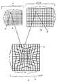
次に、図面を参照すると、図1Aは、本発明の方法による非線形拡大あるいは縮小画像解像度変換の好ましい実施例に関するディジタル化ビデオ画像I(図示せず)をプロットするために使用されるグラフ入力グリッド10の図である。この入力グリッド10は、行(ライン)12および列(ピクセル)14を特徴とし、各入力グリッド位置は、行番号(i)および列番号(j)の座標によって識別可能である。I(i,j)は、入力グリッド10でプロットでき、入力グリッド10のその位置座標が行i、および列jによって示されるディジタル化入力画像(図示せず)のピクセル16の値を示す。サイズがM行×N列のディジタル入力画像の場合、位置指標(i,j)は、下記のように入力画像サイズに制限される。すなわち、i:0,1,2,...M−1;およびj:0,1,2,...N−1である。一般に、指標iおよびjは実数あるいは整数であり得る。本発明のこの好ましい実施例では、位置座標の行iおよび列jおよび対応する位置指標(i,j)は、入力グリッド10のピクセル16の整数値位置指標に変換する整数(すなわち、実数でない)である。既知解像度を有するディジタル化ビデオ画像Iは、異なる解像度を有するディジタル化出力グリッド上のその表示を可能にするために非線形拡大あるいは縮小画像解像度変換を行うためにある。
【0013】
図1Bは、本発明の方法による非線形拡大あるいは縮小画像解像度変換の好ましい実施例に関する図1Aの解像度変換ディジタル化ビデオ画像(図示せず)をプロットするために使用された最初は空の値のグラフ出力グリッド18の図である。この出力グリッド18は、行(ライン)20および列(ピクセル)22を特徴とし、各出力グリッド位置は行番号sおよび列番号tの座標によって識別可能である。O(s,t)は、出力グリッド18でプロットでき、出力グリッド18のその位置座標が行sおよび列tによって識別されるディジタル化出力画像(図示せず)のピクセル24の値を示している。サイズがM1行×N1列のディジタル出力画像の場合、位置指標(s,t)は、次のように出力画像サイズに制限される。すなわち、s:0,1,2,...M1−1;およびt:0,1,2,...N1−1である。一般に、指標sおよびtは実数あるいは整数であり得る。本発明のこの好ましい実施例では、位置座標の行sおよび列tおよび典型的なピクセル24の対応する位置指標(s,t)は、出力グリッド18の整数(すなわち、実数でない)値である。
【0014】
図1Cは、本発明の方法による非線形拡大あるいは縮小画像変換の好ましい実施例に関する出力グリッド18(図1B)と入力グリッド10(図1A)とのマクロレベル関係を示すグラフ接続グリッド26の図である。接続グリッド26の有用性は、出力グリッド18(図1B)のピクセル位置を入力グリッド10(図1A)のピクセル位置に関連づけ、画像解像度変換中非線形効果を考慮することにある。接続グリッド26は、行(ライン)28および列30を特徴とし、各接続グリッド位置は、行番号yiおよび列番号xjの座標によって識別可能である。一般に、指標yiおよびxjは実数あるいは整数であり得る。本発明のこの好ましい実施例では、位置座標行yiおよび列xiおよび典型的なピクセル位置32の対応する位置指標(yi,xj)は、接続グリッド26の実数(すなわち整数でない)値である。
接続グリッド26(図1C)では、行yの下つき添え字iおよび列xの下つき添え字jは、出力グリッド18(図1B)でプロットできる出力画像O(s,t)(図示せず)の位置座標、すなわち指標と入力グリッド10(図1A)でプロットできる入力画像I(i,j)の位置座標、すなわち指標との間で関連づけるかあるいは接続するために使用される。接続グリッド26の典型的なピクセル位置指標(yi,xj)32は、入力グリッド10(図1A)でプロットできる入力画像I(i,j)のピクセル16の正確な位置を示す実位置指標である。
【0015】
本発明の拡大あるいは縮小画像解像度変換の好ましい実施例の非線形の場合、出力グリッド18(図1B)の出力指標(s,t)と入力グリッド10(図1A)の入力指標(i,j)との間の非線形関係は、下記のように関数的に示される。すなわちyi=Fi(s,t,a,b,λ1,μ1)およびxj=Fj(s,t,a,b,λ2,μ2)である。FiおよびFjは、非線形ピクセル位置制御関数であり、λ1,μ1,λ2,およびμ2は、入力グリッド10(図1A)から出力グリッド18(図1B)までの画像解像度変換中の非直線性の大きさを制御する自由パラメータであり、aおよびbは、出力を入力画像サイズに関連づけるスケールファクタ(比)であり、a=M1/M、すなわち(出力画像Oの行数)/(入力画像Iの行数)およびb=N1/N、すなわち(出力画像Oの列数)/(入力画像Iの列数)、ここでa>0およびb>0は実正数である。
スケールファクタaの割り当てに基づいて、接続グリッド指標32(yi,xj)の値を計算する式でのスケールファクタaの使用において、a>1の場合、入力から出力画像に変換する際に行数の増加があり、それ自体、入力グリッド10(図1A)の入力画像Iの行12は、出力グリッド18(図1B)の出力画像Oの行20に非線形拡大される。0<a<1の場合、入力から出力画像に変換する際に行数の減少があり、入力グリッド10(図1A)の入力画像Iの行12は、出力グリッド18(図1B)の出力画像Oの行20に非線形縮小される。同様に、スケールファクタbの割り当てに基づいて、b>1の場合、入力から出力画像へ変換する際に列数の増加があり、それ自体、入力グリッド10(図1A)の入力画像Iの列14は、出力グリッド18(図1B)の出力画像Oの列22に非線形拡大される。0<b<1の場合、入力から出力画像に変換する際に列数の減少があり、入力グリッド10(図1A)の入力画像Iの列14は、出力グリッド18(図1B)の出力画像Oの列22に非線形縮小される。
【0016】
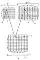
図2Aは、本発明の方法による線形拡大あるいは縮小解像度変換の好ましい実施例に関するディジタル化ビデオ画像I(図示せず)をプロットするために使用されるグラフ入力グリッド34の図である。入力グリッド34は、行(ライン)36および列(ピクセル)38を特徴とし、各入力グリッド位置は、行番号iおよび列番号jの座標によって識別可能である。I(i,j)は、入力グリッド34でプロットでき、入力グリッド34のその位置座標は行iおよび列jによって示されるディジタル化入力画像(図示せず)のピクセル40の値を示している。サイズがM行×N列のディジタル入力画像Iの場合、位置指標(i,j)は、次のように入力画像サイズに制限される。すなわち、i:0,1,2,...M−1;およびj:0,1,2,...N−1である。一般に、指標iおよびjは実数あるいは整数であり得る。本発明のこの好ましい実施例では、位置座標行iおよび列j、および対応する位置指標(i,j)は、入力グリッド34のピクセル40の整数値位置指標に変換する整数(すなわち、実数でない)である。既知解像度を有するディジタル化ビデオ画像Iは、異なる解像度を有するディジタル化出力グリッド上でその表示を可能にするために線形拡大あるいは縮小画像解像度変換を行うためにある。
【0017】
図2Bは、本発明の方法による線形拡大あるいは縮小画像解像度変換の好ましい実施例に関する図2Aの解像度変換ディジタル化ビデオ画像(図示せず)をプロットするために使用される最初は空の値のグラフ出力グリッド42の図である。出力グリッド42は、行(ライン)44および列(ピクセル)46を特徴とし、各出力グリッド位置は、行番号sおよび列番号tの座標によって識別可能である。O(s,t)は、出力グリッド42でプロットでき、出力グリッド42のその位置座標が行s、および列tによって示されるディジタル化出力画像(図示せず)のピクセル48の値を示す。サイズM1行×N1列のディジタル出力画像の場合、位置指標(s,t)は、次のように入力画像サイズに制限される。すなわち、s:0,1,2,...M−1−1;およびt:0,1,2,...N−1−1である。一般に、指標sおよびtは実数あるいは整数であり得る。本発明のこの好ましい実施例では、位置座標行sおよび列t、および典型的なピクセル48の対応する位置指標(s,t)は、出力グリッド42の整数(すなわち、実数でない)値である。
図2Cは、本発明の方法による線形拡大あるいは縮小画像解像度変換の好ましい実施例に関する出力グリッド42(図2B)と入力グリッド34(図2A)との間のマクロレベル関係を示すグラフ接続グリッド50の図である。接続グリッド50の有用性は、出力グリッド42(図2B)のピクセル位置を入力グリッド34(図2A)のピクセル位置に関連づけ、画像解像度変換中線形効果を考慮することにある。接続グリッド50は、行(ライン)52および列54を特徴とし、各接続グリッド位置は、行番号yiおよび列番号xjの座標によって識別可能である。一般に、指標yiおよびxjは実数あるいは整数であり得る。本発明のこの好ましい実施例では、位置座標行yiおよび列xiおよび典型的なピクセル位置56の対応する位置指標(yi,xj)は、接続グリッド50の実数(すなわち整数でない)値である。
【0018】
接続グリッド50(図2C)では、行yの下つき添え字iおよび列xの下つき添え字jは、出力グリッド42(図2B)でプロットできる出力画像O(s,t)(図示せず)の位置座標、すなわち指標と入力グリッド34(図2A)でプロットできる入力画像I(i,j)の位置座標、すなわち指標との間で関連づけるかあるいは接続するために使用される。接続グリッド50の典型的なピクセル位置指標(yi,xj)56は、入力グリッド34(図2A)でプロットできる入力画像I(i,j)のピクセル40の正確な位置を示す実位置指標である。
本発明の拡大あるいは縮小画像解像度変換の好ましい実施例の線形の場合、出力グリッド42(図2B)の出力指標(s,t)と入力グリッド34(図2A)の入力指標(i,j)との間の線形関係は、下記のように関数的に示される。すなわちyi=Fi(s,t,a,b,λ1,μ1)およびxj=Fj(s,t,a,b,λ2,μ2)である。FiおよびFjは、線形ピクセル位置制御関数であり、λ1,μ1,λ2,およびμ2は、入力グリッド10(図1A)から出力グリッド18(図1B)までの画像解像度変換中使用されてもよい自由パラメータであり、aおよびbは、出力を入力画像サイズに関連づけるスケールファクタ(比)であり、a=M1/M、すなわち(出力画像Oの行数)/(入力画像Iの行数)およびb=N1/N、すなわち(出力画像Oの列数)/(入力画像Iの列数)、ここでa>0およびb>0は実正数である。
スケールファクタa>1の場合、入力から出力画像に変換する際に行数の増加があり、入力グリッド34(図2A)の入力画像Iの行36は、出力グリッド42(図2B)の出力画像Oの行44に線形拡大される。0<a<1の場合、入力から出力画像に変換する際に行数の減少があり、入力グリッド34(図2A)の入力画像Iの行36は、出力グリッド42(図2B)の出力グリッドOの行44に線形縮小される。スケールファクタb>1の場合、入力から出力画像へ変換する際に列数の増加があり、入力グリッド34(図2A)の入力画像Iの列38は、出力グリッド42(図2B)の出力画像Oの列46に線形拡大される。0<b<1の場合、入力から出力画像に変換する際に列数の減少があり、入力グリッド34(図2A)の入力画像Iの列38は、出力グリッド42(図2B)の出力画像Oの列46に線形縮小される。
【0019】
図3は、本発明による拡大あるいは縮小画像解像度変換の非線形および線形方法の好ましい実施例のフロー図である。図3に示された本発明による拡大あるいは縮小画像解像度変換の非線形および線形方法の好ましい実施例は、一般に非線形の拡大あるいは縮小画像解像度変換の場合、あるいは線形の拡大あるいは縮小画像解像度変換の場合のいずれかに適用できる。非線形あるいは線形の拡大あるいは縮小画像解像度変換の場合に対する本発明のこの好ましい実施例の用途の特定の差異は図3の下記の説明にはっきりと示される。
図3において、拡大あるいは縮小画像解像度変換の非線形および線形方法の各々の通常の応用可能な動作原理ステップは番号付けられ、枠内に納められる。図3の下記の説明に生じる表示および記号は、非線形の拡大あるいは縮小画像解像度変換の特定の場合に対して、図1A、図1B、および図1Cの説明に使用される表示および記号と一致し、線形の拡大あるいは縮小画像解像度変換の特定の場合に対して、図2A、図2B、および図2Cの説明で使用される表示および記号と一致している。図3の説明に含まれているのは、関連用語の定義、数式、および図3に示された拡大あるいは縮小画像解像度変換の非線形および線形方法の示された動作原理方法ステップをさらに示す1つあるいはそれ以上のサブステップである。サブステップは括弧の文字で示され、乗算演算はアステリスク(*)によって示される。
【0020】
次に図3を参照すると、本発明による拡大あるいは縮小画像解像度変換の非線形および線形方法の好ましい実施例は下記の通りである。
ステップ1では、既知解像度を有する入力画像および異なる解像度を有するその目標出力画像が特徴づけられる。ステップ(a)では、入出力画像グリッドおよびこのグリッドのそれぞれの座標系は、下記のように規定され、設定される(非線形画像解像度変換の場合に対して図1Aおよび図1B;および線形画像解像度変換の場合に対して図2Aおよび図2B)。
I(i,j)は、入力グリッド(図1Aの10、あるいは図2Aの34)でプロットでき、入力グリッド(図1Aの10、あるいは図2Aの34)のその位置座標が行iおよび列jで示されるディジタル化入力画像(図示せず)のピクセル(図1Aの16、あるいは図2Aの40)の値を示す。サイズがM行×N列のディジタル入力画像Iの場合、位置指標(i,j)は下記のように入力画像サイズに制限される。すなわち、i:0,1,2,...M−1;およびj:0,1,2,...N−1である。一般に、指標iおよびjは実数あるいは整数であり得る。本発明のこの好ましい実施例では、位置座標行iおよび列jおよび対応する位置指標(i,j)は、入力ピクセル(図1Aの16、あるいは図2Aの40)の整数値位置指標に変換する整数(すなわち、実数でない)である。
【0021】
O(s,t)は、最初が空の値の出力グリッド(図1Bの18、あるいは図2Bの42)でプロットでき、出力グリッド(図1Bの18、あるいは図2Bの42)のその位置座標が行sおよび列tで示されるディジタル化入力画像(図示せず)のピクセル(図1Bの24、あるいは図2Bの48)の値を示す。サイズがM1行×N1列のディジタル出力画像Oの場合、位置指標(s,t)は下記のように出力画像サイズに制限される。すなわち、s:0,1,2,...M1−1;およびt:0,1,2,...N1−1である。一般に、指標sおよびtは実数あるいは整数であり得る。本発明のこの好ましい実施例では、位置座標行sおよび列tおよび対応する位置指標(s,t)は、出力ピクセル(図1Bの24、あるいは図2Bの48)の整数値位置指標に変換する整数(すなわち、実数でない)である。
ステップ1のステップ(b)では、下記のように入力画像Iを目標出力画像Oに変換する際に、行数および列数の変化に基づいて、画像サイズの変化による入力画像解像度の拡大、縮小、あるいは混合モード拡大および縮小のようなスケーリングモードの決定が行われる。
【0022】
出力を入力画像サイズに関連づけるスケーリングファクタ(比)のようなaおよびbを規定する。ここで、a=M1/M、すなわち(出力画像Oの行数)/(入力画像Iの行数)およびb=N1/N、すなわち(出力画像Oの列数)/(入力画像Iの列数)、ここでa>0およびb>0は実正数である。
スケールファクタa>1の場合、入力から出力画像に変換する際に行数の増加がある。入力グリッド10(図1A)の入力画像Iの行12は、出力グリッド18(図1B)の出力画像Oの行20に非線形拡大されるかあるいは入力グリッド34(図2A)の入力画像Iの行36は、出力グリッド42(図2B)の出力画像Oの行44に線形拡大される。0<a<1の場合、入力から出力画像に変換する際に行数の減少がある。入力グリッド10(図1A)の入力画像Iの行12は、出力グリッド18(図1B)の出力画像Oの行20に非線形縮小されるかあるいは入力グリッド34(図2A)の入力画像Iの行36は、出力グリッド42(図2B)の出力画像Oの行44に線形縮小される。
【0023】
スケールファクタb>1の場合、入力から出力画像へ変換する際に列数の増加がある。入力グリッド10(図1A)の入力画像Iの列14は、出力グリッド18(図1B)の出力画像Oの列22に非線形拡大されるかあるいは入力グリッド34(図2A)の入力画像Iの列38は、出力グリッド42(図2B)の出力画像Oの列46に線形拡大される。0<b<1の場合、入力から出力画像に変換する際に列数の減少がある。入力グリッド10(図1A)の入力画像Iの列14は、出力グリッド18(図1B)の出力画像Oの列22に非線形縮小されるかあるいは入力グリッド34(図2A)の入力画像Iの列38は、出力グリッド42(図2B)の出力画像Oの列46に線形縮小される。
ステップ1のステップ(c)では、画像解像度変換が下記のように入力画像のアスペクト比に対する出力画像のアスペクト比の比により非線形かあるいは線形であるかどうかの決定が行われる。
すなわち、
M1:N1=出力画像アスペクト比。
M:N=入力画像アスペクト比。
M1:N1≠M:Nの場合、非線形拡大あるいは非線形縮小画像解像度変換は、好ましくは、入力画像(図1Aの10)に適用される。
M1:N1=M:Nの場合、線形拡大あるいは線形縮小画像解像度変換は、好ましくは入力画像(図2Aの34)に適用される。
【0024】
ステップ2では、入力画像(図1Aの10、あるいは図2Aの34)は、標準FIR畳み込み方法により、FIR(有限インパルス応答フィルタ)で畳み込まれる。
ステップ3では、出力画像グリッド(図1Bの18、あるいは図2Bの42)のピクセル位置(s,t)を入力画像グリッド(図1Aの10、あるいは図2Aの34)に関連づけるために使用されるピクセル位置制御関数が規定される。非線形あるいは線形の拡大あるいは縮小画像解像度変換のいずれかに適用可能であるピクセル位置制御関数の一般形式は下記のように示される。
入力画像(図1Aの10、あるいは図2Aの34)の座標iのスケーリング行の場合、Fi=F(s,t,a,b,λ1,μ1)および
入力画像(図1Aの10、あるいは図2Aの34)の座標jのスケーリング列の場合、Fi=F(s,t,a,b,λ2,μ2)、ここで、λ1,μ1,λ2,およびμ2は、入力グリッド(図1Aの10、あるいは図2Aの34)から出力グリッド(図1Bの18、あるいは図2Bの42)までの画像解像度変換中の非直線性の大きさを制御する自由パラメータであり、aおよびbは出力を入力画像サイズに関連づけるスケールファクタ(比)であり、ここでa=M1/M、およびb=N1/Nであり、ここでa>0およびb>0は実正数である。非線形拡大あるいは縮小画像解像度変換の場合、非線形位置制御関数は、好ましくは接続グリッド(図1Cの26)にある出力画像ピクセルの実位置座標を計算する際に使用される。線形拡大あるいは縮小画像解像度変換の場合、線形位置制御関数は、好ましくは接続グリッド(図2Cの50)にある出力画像ピクセルの実位置座標を計算する際に使用される。
ステップ3も、予め規定されたピクセル位置制御関数による出力画像および入力画像(非線形画像解像度変換の場合は図1C;および線形画像解像度変換の場合は図2C)の位置間の接続に基づいたおよびこの接続をグラフで示す接続グリッドおよびその関連座標系の定義および設定を含む。具体的な目的のために、接続グリッドは、非線形および線形の拡大あるいは縮小画像解像度変換の各場合に対して規定され、設定される。
【0025】
非線形の拡大あるいは縮小画像解像度変換の場合、接続グリッド26(図1C)は、出力グリッド18(図1B)と入力グリッド10(図1A)との間のマクロレベル関係を示す。接続グリッド26(図1C)は、出力グリッド18(図1B)のピクセル位置を入力グリッド10(図1A)のピクセル位置に関連づけ、画像解像度変換中非線形効果を考慮する。接続グリッド26(図1C)は、行28および列30を特徴とし、各接続グリッド位置は、行番号yiおよび列番号xjの座標によって識別可能である。一般に、指標yiおよびxjは実数あるいは整数であり得る。本発明の好ましい実施例では、位置座標行yiおよびxjおよび典型的なピクセル位置32の対応する位置指標(yi,xj)は、接続グリッド26(図1C)で実数(すなわち、整数でない)値である。接続グリッド26(図1C)では、行yの下つき添え字iおよび列xの下つき添え字jは、出力グリッド18(図1B)でプロットできる出力画像O(s,t)の位置座標、すなわち指標と入力グリッド10(図1A)でプロットできる入力画像I(i,j)の位置座標、すなわち指標との間を関連づけるかあるいは接続するために使用される。接続グリッド26(図1C)の典型的なピクセル位置指標(yi,xj)32は、入力グリッド10(図1A)でプロットできる入力画像I(i,j)のピクセル16の正確な位置を示す実位置指標である。接続グリッド26(図1C)の実ピクセル位置座標(yi,xj)32は、予め規定されたピクセル位置制御関数の非線形形式を使用して計算されるのが好ましい。
【0026】
線形拡大あるいは縮小画像解像度変換の場合、接続グリッド50(図2C)は、出力グリッド42(図2B)と入力グリッド34(図2A)との間のマクロレベル関係を示す。接続グリッド50(図2C)の有用性は、出力グリッド42(図2B)のピクセル位置を入力グリッド34(図2A)のピクセル位置に関連づけ、画像解像度変換中線形効果を考慮することにある。接続グリッド50(図2C)は、行52および列54を特徴とし、各接続グリッド位置は行番号yiおよび列番号xjの座標によって識別可能である。一般に、指標yiおよびxjは実数あるいは整数であり得る。本発明のこの実施例では、位置座標行yiおよび列xjおよび典型的なピクセル位置56の対応する位置指標(yi,xj)は、接続グリッド50(図2C)の実数(すなわち、整数でない)値である。接続グリッド50(図2C)において、行yの下つき添え字iおよび列xの下つき添え字jは、出力グリッド42(図2B)でプロットでき出力画像O(s,t)の位置座標、すなわち指標と入力グリッド34(図2A)でプロットできる入力画像I(i,j)の位置座標、すなわち指標との間で関連づけるかあるいは接続するために使用される。接続グリッド50の典型的なピクセル位置指標(yi,xj)56は、入力グリッド34(図2A)でプロットできる入力画像I(i,j)のピクセル40の正確な位置を示す実位置指標である。接続グリッド26(図1C)の実ピクセル位置座標(yi,xj)32は、好ましくは予め規定されたピクセル位置制御関数の線形形式を使用して計算される。
【0027】
ステップ4では、入力画像グリッド内に埋め込まれた出力画像ピクセルの実位置座標は、ステップ3のピクセル位置制御関数を使用して計算される。具体的な目的で、出力画像ピクセルの実位置座標の計算は、非線形、および線形、拡大あるいは縮小画像解像度変換の各場合に対して示される。
非線形拡大あるいは縮小画像解像度変換(図1A、図1B、および図1C)の場合、ステップ3のピクセル位置制御関数を使用する、入力画像グリッド内に埋め込まれた出力画像ピクセルの実位置座標の計算に関する非線形拡大あるいは縮小画像解像度の3つのモード(a)、(b)、および(c)はここに特徴づけられている。非線形ピクセル位置制御関数の数値を求めるのに必要とされるパラメータおよびその値領域が説明される。
【0028】
非線形モード(a):垂直および水平非線形スケーリング、それによって入力画像グリッド10(図1A)の入力画像I(図示せず)の列数(the number of column)14(図1A)および行数(the number of row)12(図1A)は、出力画像グリッド(図1B)の出力画像O(図示せず)の列数22(図1B)および行数20(図1B)のそれぞれに非線形拡大あるいは縮小される。
行数の垂直非線形スケーリングの場合、パラメータA0、A1、およびA2を下記のように規定する。
U=λ2 *(b/a)、およびY=1/[(μ2 *b)+(1−μ2)*a]、ここで、UおよびYは、パラメータA0、A1、およびA2の計算のために使用された画像解像度変換の非直線性の大きさに関連した下記の第2次多項式の係数の非直線性の大きさを制御するパラメータである。
TmpA0=[Y−1/a−U*(1/a−1/b)]/[U*(U−1)]、
TmpA1=1/b−1/a−TmpA0、
A0=TmpA0/(M12*M12)、
A1=TmpA1/M12、および
A2=1/b
TmpA0およびTmpA1は自由パラメータであり、M12は、ハーフサイズとして規定され、M12=M1/2として計算される、すなわちM12は、出力画像グリッド18(図1B)の出力画像Oの行数20(図1B)の1/2に等しい。M12の有用性は、出力画像ピクセルの実位置の計算を接続グリッド26(図1C)の中心で開始できることにある。これは、出力画像グリッド18(図1B)の出力画像Oのアスペクト比が入力画像グリッド10(図1A)の入力画像Iのアスペクト比に等しく保持される出力画像グリッド18(図1B)の対称解像度変換出力画像Oを中心外部から発生することになり、それによって出力画像グリッド18(図1B)の解像度変換出力画像Oの中心部は入力画像グリッド10(図1A)の元の入力画像の中心部をきっちりと示し、それによって画像解像度変換中の非線形効果による歪みは出力画像グリッド18(図1B)の新しく発生された出力画像Oのコーナーまで拡大される。
【0029】
s=0,1,2,...M1の場合の座標sを有する出力画像グリッド18(図1B)の各行20(図1B)に関して、下記の式を計算する。
△r=s−M12、ここで、△rの範囲は−M2からM2−1までである。
Tangent_row=(A0*△r *△r)+A1*|△r|+A2、および
Fi=△r *(Tangent_row)+M2、ここでFiは、一般ピクセル位置制御関数の特定形式に相当する実数であり、入力画像グリッド10(図1A)の座標iのスケーリング係数に対して、Fi=F(s,t,a,b,λ1,μ1)である。接続グリッド26(図1C)にある出力ピクセル24(図1Bの出力画像グリッド18にある)の実位置(yi,xj)の行座標yiは、下記のようにFiから計算される。
yi=Fi=△r *(Tangent_row)+M2
列数の水平非線形スケーリングの場合、パラメータP0、P1、およびP2を下記のように規定する。
【0030】
W=λ1 *(a/b)、およびV=1/[(λ1 *a)+(1−λ1)*b]、WおよびVは、パラメータP0、P1、およびP2の計算のために使用される画像解像度変換の非直線性の大きさに関連する下記の2次多項式の係数の非直線性の大きさを制御するパラメータである。
TmpP0=[V−1/a−W*(1/b−1/a)]/[W*(W−1)]、
TmpP1=1/b−1/a−TmpP0、
P0=TmpP0/(N12*N12)、
P1=TmpP1/N12、および
P2=1/a
TmpP0およびTmpP1は自由パラメータであり、N12は、ハーフサイズとして規定され、N12=N1/2として計算される、すなわちN12は、出力画像グリッド18(図1B)の出力画像Oの列数22(図1B)の1/2に等しい。N12の有用性は、出力画像ピクセルの実位置の計算を接続グリッド26(図1C)の中心で開始できることにある。これは、出力画像グリッド18(図1B)の出力画像Oのアスペクト比が入力画像グリッド10(図1A)の入力画像Iのアスペクト比に等しく保持される出力画像グリッド18(図1B)の対称解像度変換出力画像Oを中心外部から発生することになり、それによって出力画像グリッド18(図1B)の解像度変換出力画像Oの中心部は入力画像グリッド10(図1A)の元の入力画像の中心部をきっちりと示し、それによって画像解像度変換中の非線形効果による歪みは出力画像グリッド18(図1B)の新しく発生された出力画像Oのコーナーまで拡大される。
【0031】
t=0,1,2,...M1の場合の座標tを有する出力画像グリッド18(図1B)の各列22(図1B)に関して、下記の式を計算する。
△c=t−N12、ここで、△cの範囲は−N2からN2−1までである。
Tangent_column=(P0*△c *△c)+P1*|△c|+P2、および
Fj=△c *(Tangent_column)+N2、ここでFjは、一般ピクセル位置制御関数の特定形式に相当する実数であり、入力画像グリッド10(図1A)の座標jのスケーリング係数に対して、Fj=F(s,t,a,b,λ2,μ2)である。接続グリッド26(図1C)にある出力ピクセル24(図1Bの出力画像グリッド18にある)の実位置(yi,xj)の列座標xjは、下記のようにFjから計算される。
xj=Fj=△c *(Tangent_column)+N2
したがって、出力画像Oの行数および列数のそれぞれに対する入力画像Iの行数および列数の両方の垂直および水平の非線形スケーリングを特徴とする非線形モード(a)の場合、入力画像グリッド内に埋め込まれた出力画像ピクセルの実位置座標(yi,xj)の計算は、ステップ3のピクセル位置制御関数の特定の形式を使用して下記のように行われる。
yi=Fi=△r *(Tangent_row)+M2、および
xj=Fj=△c *(Tangent_column)+N2
【0032】
非線形モード(b):垂直非線形スケーリングのみ、それによって入力画像グリッド10(図1A)の入力画像I(図示せず)の行数12(図1A)は、出力画像グリッド18(図1B)の出力画像O(図示せず)の行数20(図1B)に非線形拡大あるいは縮小される。入力画像グリッド10(図1A)の座標iのスケーリング行に対する一般ピクセル位置制御関数Fi=F(s,t,a,b,λ1,μ1)の特定の形式は、垂直非線形スケーリングの場合の非線形スケーリングモード(a)のFi=△r *(Tangent_row)+M2の形式と同じであり、ここでFiは実数である。接続グリッド26(図1C)にある出力ピクセル24(図1Bの出力画像グリッド18にある)の実位置(yi,xj)の行座標yiは、Fiから下記のように計算される。
yi=Fi=△r *(Tangent_row)+M2
入力画像グリッド10(図1A)の入力画像Iの列数14(図1A)は、下記のように出力画像グリッド18(図1B)の出力画像Oの列数22(図1B)に線形拡大あるいは縮小される。
座標tを有する出力画像グリッド18の各列22(図1B)に関して、t=0、1、2、...N1の場合、下記のように計算する。
【0033】
Fj=t/b、ここで、Fjは、入力画像グリッド10(図1A)の座標jのスケーリング列に対して一般ピクセル位置制御関数Fj=F(s,t,a,b,λ2,μ2)の特定の形式に相当する実数である。接続グリッド26(図1C)にある出力ピクセル24(図1Bの出力画像グリッド18にある)の実位置(yi,xj)の列座標xjは、下記のようにFjから計算される。
xj=Fj=t/b
したがって、出力画像Oの行数に対する入力画像Iの行数だけの垂直非線形スケーリングおよび出力画像Oの列数に対する入力画像Iの列数の線形スケーリングを特徴とする非線形モード(b)の場合、入力画像グリッド内に埋め込まれた出力画像ピクセルの実位置座標(yi,xj)の計算は、下記のようにステップ3のピクセル位置制御関数の特定の形式を使用して行われる。
yi=Fi=△r *(Tangent_row)+M2、および
xj=Fj=t/b
【0034】
非線形モード(c):水平非線形スケーリングのみ、それによって入力画像グリッド10(図1A)の入力画像I(図示せず)の列数14(図1A)は、出力画像グリッド18(図1B)の出力画像O(図示せず)の列数22(図1B)に非線形拡大あるいは縮小される。入力画像グリッド10(図1A)の座標jのスケーリング列に対する一般ピクセル位置制御関数Fj=F(s,t,a,b,λ2,μ2)の特定の形式は、水平非線形スケーリングの場合の非線形モード(a)のFj=△c *(Tangent_column)+N2の形式と同じであり、ここでFjは実数である。接続グリッド26(図1C)にある出力ピクセル24(図1Bの出力画像グリッド18にある)の実位置(yi,xj)の列座標xjは、Fjから下記のように計算される。
xj=Fj=△c *(Tangent_column)+N2
入力画像グリッド10(図1A)の入力画像Iの行数12(図1A)は、下記のように出力画像グリッド18(図1B)の出力画像Oの行数20(図1B)に線形拡大あるいは縮小される。
座標sを有する出力画像グリッド18の各行20(図1B)に関して、s=0、1、2、...M1の場合、下記のように計算する。
【0035】
Fi=s/a、ここで、Fiは、入力画像グリッド10(図1A)の座標iのスケーリング列に対して一般ピクセル位置制御関数Fi=F(s,t,a,b,λ1,μ1)の特定の形式に相当する実数である。接続グリッド26(図1C)にある出力ピクセル24(図1Bの出力画像グリッド18にある)の実位置(yi,xj)の行座標yiは、下記のようにFiから計算される。
yi=Fi=s/a
したがって、出力画像Oの列数に対する入力画像Iの列数だけの水平非線形スケーリングおよび出力画像Oの行数に対する入力画像Iの行数の線形スケーリングを特徴とする非線形モード(c)の場合、入力画像グリッド内に埋め込まれた出力画像ピクセルの実位置座標(yi,xj)の計算は、下記のようにステップ3のピクセル位置制御関数の特定の形式を使用して行われる。
yi=Fi=s/a、および
xj=Fj=△c *(Tangent_column)+N2
線形拡大あるいは縮小画像解像度変換(図2A、図2B、および図2C)の場合、ステップ3のピクセル位置制御関数を使用する入力画像グリッド内に埋め込まれた出力画像ピクセルの実位置座標の計算はここで特徴づけられる。
垂直線形スケーリングの場合、入力画像グリッド34(図2A)の入力画像I(図示せず)の行数36(図2A)は、下記のように出力画像グリッド42(図2B)の出力画像O(図示せず)の行数44(図2B)に線形拡大あるいは縮小される。
【0036】
座標sを有する出力画像グリッド42(図2B)の各行44(図2B)に関しては、s=0,1,2,...M1の場合、下記のように計算する。
Fi=s/a、ここで、Fiは、入力画像グリッド34(図2A)の座標iのスケーリング行に対する一般ピクセル位置制御関数Fi=F(s,t,a,b,λ1,μ1)の特定の形式に相当する実数である。接続グリッド50(図2C)にある出力ピクセル48(図2Bの出力画像グリッド42にある)の実位置(yi,xj)の行座標yiは、下記のようにFiから計算される。
yi=Fi=s/a
水平線形スケーリングの場合、入力画像グリッド34(図2A)の入力画像I(図示せず)の列数38(図2A)は、下記のように出力画像グリッド42(図2B)の出力画像O(図示せず)の列数46(図2B)に線形拡大あるいは縮小される。
座標tを有する出力画像グリッド42(図2B)の各列46(図2B)に関しては、t=0,1,2,...N1の場合、下記のように計算する。
Fj=t/b、ここで、Fjは、入力画像グリッド34(図2A)の座標jのスケーリング列に対する一般ピクセル位置制御関数Fj=F(s,t,a,b,λ2,μ2)の特定の形式に相当する実数である。接続グリッド50(図2C)にある出力ピクセル48(図2Bの出力画像グリッド42にある)の実位置(yi,xj)の列座標xjは、下記のようにFjから計算される。
xj=Fj=t/b
したがって、出力画像Oの行数に対する入力画像Iの行数の線形垂直スケーリングおよび出力画像Oの列数に対する入力画像Iの列数の線形水平スケーリングの場合、入力画像グリッド内に埋め込まれた出力画像ピクセルの実位置座標(yi、xj)の計算は、下記のようにステップ3のピクセル位置制御関数の特定の形式を使用して行われる。
yi=Fi=s/a、および
xj=Fj=t/b
【0037】
ステップ5では、出力画像ピクセル位置座標(非線形拡大あるいは縮小画像解像度変換の場合、図1Bの出力画像グリッド18の24、あるいは線形拡大あるいは縮小画像解像度変換の場合、図2Bの出力画像グリッド42の48)の実ピクセル位置座標(ステップ4の非線形あるいは線形ピクセル位置制御関数から計算された非線形拡大あるいは縮小画像解像度変換の場合、図1Cの接続グリッド26の32、あるいは線形拡大あるいは縮小画像解像度変換の場合、接続グリッド50の56)を囲む入力画像グリッド(非線形拡大あるいは縮小画像解像度変換の場合、図1Aの10、あるいは線形拡大あるいは縮小画像解像度変換の場合、図2Aの34)の隣接ピクセルの位置座標、すなわち指標の識別がある。
例として、各々が、接続グリッドに位置決めされた出力画像ピクセル位置の実ピクセル位置座標を囲む入力画像グリッドの隣接ピクセルの位置座標の識別の本発明の非線形あるいは線形の拡大あるいは縮小画像解像度変換のいずれかの場合に適用可能な2つの代替の好ましい実施例がここで特徴づけされる。第1の実施例は、9つの隣接ピクセル位置に基づいていて、第2の実施例は、4つの隣接ピクセル位置に基づいている。一般に、n個の隣接ピクセル位置は、本発明の方法のステップ5のために使用できる。
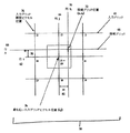
接続グリッドに位置決めされた出力画像ピクセル位置の実ピクセル位置座標を囲む入力画像グリッドの9つの隣接ピクセル位置を特徴とする第1の代替の好ましい実施例では、入力画像グリッド(非線形拡大あるいは縮小画像解像度変換の場合、図1Aの10、あるいは線形拡大あるいは縮小画像解像度変換の場合、図2Aの34)を接続グリッド(非線形拡大あるいは縮小画像解像度変換の場合、図1Cの26、あるいは線形拡大あるいは縮小画像解像度変換の場合、図2Cの50)に関連づける整数値入力グリッドピクセル位置と実数値接続グリッドピクセル位置との間のマイクロレベル関係を示すマイクログリッド58の図の参照が図4に対して行われる。
【0038】
図4のマイクログリッド58は、その対応する入力画像グリッドピクセル位置座標行i62および列j64を有する入力画像グリッド60およびその対応する接続グリッドピクセル位置座標行yi68および列xj70を有する接続グリッド66を特徴とする。接続グリッド位置座標(yi,xj)72は、ステップ4で予め計算された入力画像グリッド内に埋め込まれた出力ピクセル位置座標(s,t)の実位置座標を示している。整数値入力画像グリッドピクセル位置座標(i,j)は、下記のように実数値接続グリッドピクセル位置座標(yi,xj)から計算される。
i(整数値)=フロア(yi+0.5)、および
j(整数値)=フロア(xj+0.5)
一般に、ピクセル位置座標iおよびjは実数あるいは整数であり得る。本発明のこの好ましい実施例では、位置座標行iおよび列j、および対応する位置指標(i,j)は、フロア関数から計算される整数(すなわち、実数ではない)であるが、一般に他の関数はこの計算のために使用されてもよい。
【0039】
図4では、接続グリッド66の実数値接続グリッド位置座標(yi,xj)72を囲む入力画像グリッド60の9つの隣接ピクセルi1〜i9(例えば、i1として76)の整数値入力画像グリッド位置座標は、最も近い入力グリッドピクセルiN74の入力画像グリッドピクセル位置座標(i,j)から識別され、この位置座標(i,j)を含む。入力画像グリッド隣接ピクセルの奇数番号を特徴とする本発明の方法のこの他の好ましい実施例では、最も近い入力画像グリッドピクセルiN74の位置は、9つの入力画像グリッド隣接ピクセルi1〜i9の中心位置として選択され、割り当てられたピクセル位置座標(i,j)である。値i1、i2、i3、i4、i5、i6、i7、i8、およびi9を有する9つの入力画像グリッド隣接ピクセルは、下記のように下記の整数値入力画像グリッド座標、すなわち、(i−1,j−1)、(i−1,j)、(i−1,j+1)、(i,j−1)、(i,j)、(i,j+1)、(i+1,j−1)、(i+1,j)、および(i+1,j+1)のそれぞれに割り当てられる。
【0040】
ここに説明されているが、図示されていない第2の他の好ましい実施例は、接続グリッドに位置決めされた出力画像ピクセル位置の実ピクセル位置座標を囲む入力画像グリッドの4つの隣接ピクセル位置を特徴とする。実数値接続グリッド位置座標(yi,xj)を囲む整数値入力グリッド隣接ピクセル位置座標(i、j)は、下記のように実数値接続グリッドピクセル位置座標(yi,xj)から計算される。
i(整数値)=フロア(yi)、および
j(整数値)=フロア(xj)
入力グリッド隣接ピクセルの奇数を特徴とする本発明の方法のこの他の好ましい実施例では、中心入力画像グリッド隣接ピクセルが全然ない。最も近い入力画像グリッドピクセルiNの整数値位置座標(i0,j0)は下記のように計算される。
i0(整数値)=フロア(yi+0.5)、および
j0(整数値)=フロア(xj+0.5)
一般に、ピクセル位置座標iおよびj、およびi0およびj0は実数あるいは整数であり得る。本発明のこの好ましい実施例では、位置指標(i,j)、および(i0,j0)は、フロア関数から計算される整数(すなわち、実数ではない)であるが、それぞれ一般に他の関数はこの計算のために使用されてもよい。
【0041】
接続グリッドの実数値接続グリッド位置座標(yi,xj)を囲む入力画像グリッドの4つの隣接ピクセルi1、i2、i3、およびi4の整数値位置座標は、下記のように、すなわち、(i,j)、(i,j+1)、(i,j+1)、および(i+1,j+1)それぞれに割り当てられる。これらの4つの隣接ピクセルの値から局所係数を計算する(ステップ7)目的で、入力画像グリッドの最も近いピクセルiNのピクセル位置座標(i0,j0)は4つの隣接ピクセル位置座標の一つとして割り当てられる。
9つあるいは4つの隣接ピクセル位置を特徴とする各他の好ましい実施例に適用可能なステップ6では、実数値出力ピクセル、あるいは接続グリッド、位置座標(yi,xj)(ステップ4で非線形あるいは線形ピクセル位置制御関数から計算される)と整数値隣接ピクセル位置(ステップ5で識別され、計算される)とのデルタ行およびデルタ列関数差は下記のように規定され、計算される。
Ki>0の場合、デルタ行、dr=(yi−i)*Ki、および
Kj>0の場合、デルタ列、dc=(xj−j)*Kj、ここでKiおよびKjは実数値パラメータであり、drおよびdcは実数である。デルタ行drおよびデルタ列dcは、9つあるいは4つのいずれかの隣接ピクセル位置を特徴とする具体的な他の実施例ならびに入力ピクセル位置を接続グリッドに位置決めされた実数値出力ピクセル位置に関連づけるマイクログリッドに構成されるようなm個の隣接ピクセル位置の場合の両方に適用可能である。
【0042】
9つの隣接ピクセル位置を特徴とする第1の他の好ましい実施例を示す図4では、マイクログリッド58のdr78は、デルタ行、すなわち入力グリッド60にある最も近い隣接ピクセルi5=iN74の整数値入力画像ピクセル位置座標(i,j)の行i62と接続グリッド66にある出力画像ピクセル位置の実数値ピクセル位置座標(yi,xj)72の行yi68との差を示す。同様に、マイクログリッド58のdc80は、デルタ列、すなわち入力グリッド60にある最も近い隣接ピクセルi5=iN74の整数値入力画像ピクセル位置座標(i,j)の列j64と接続グリッド66にある出力画像ピクセル位置の実数値ピクセル位置座標(yi,xj)72の列xj70との差を示す。
本発明の非線形、あるいは線形の拡大あるいは縮小画像解像度変換の場合のいずれかに適用可能なステップ7では、実ピクセル位置(ステップ4の非線形あるいは線形ピクセル位置制御関数から計算される)を囲む隣接ピクセル(その位置がステップ5で識別される)に対する既知値の割り当てがある。入力画像グリッド60(図4)の9つの隣接ピクセル位置を特徴とする第1の他の好ましい実施例(図4のマイクログリッド58)では、9つの隣接ピクセルの既知値は下記のように割り当てられる。
i1=I(i-1,j-1)、 i2=I(i-1,j)、 i3=I(i-1,j+1)、
i4=I(I,j-1)、 i5=iN=I(I,j)、 i6=I(I,j+1)、
i7=I(i+1,j-1)、 i8=I(i+1,j)、 および i9=I(i+1,j+1)
ここで、i5=iNは、接続グリッド66にある出力画像ピクセル位置の実数値ピクセル位置座標(yi,xj)72に最も近い図4の入力グリッドピクセル位置(i,j)74の値を示す。
【0043】
入力画像グリッドの4つの隣接ピクセル位置を特徴とする第2の好ましい他の実施例(図示せず)では、4つの隣接ピクセルの既知値は下記のように割り当てられる。
i1=I(I,j)、 i2=I(I,j+1)
i3=I(I,j+1)、 および i4=I(i+1,j+1)
ここで、接続グリッドの実数値接続グリッド位置座標(yi,xj)に最も近い入力画像グリッドピクセル位置(i0,j0)を有する入力画像グリッド隣接ピクセルiNの値は4つの入力画像グリッド隣接ピクセルi1、i2、i3、あるいはi4の値の中の1つから割り当てられる。
本発明の非線形、あるいは線形の拡大あるいは縮小画像解像度変換に適用可能なステップ8では、実ピクセル位置(ステップ4の非線形あるいは線形ピクセル位置制御関数から計算される)を囲む入力画像グリッド(ステップ7で割り当てられた)の隣接ピクセルの既知値からの局所係数の定義および計算がある。これらの局所係数の値は出力ピクセルの予備値を計算する際に使用される(ステップ9)。
接続グリッド66の実ピクセル位置72を囲む入力画像グリッド60の9つの隣接ピクセル76を特徴とする第1の他の好ましい実施例(図4のマイクログリッド58)では、9つの局所係数は、下記のように取り囲む9つの隣接ピクセルの既知値の線形結合を使用することによって規定され、計算される。
【0044】
ケース1:囲む隣接ピクセルの左へシフト
a1=+4*i1-8*i2+4*i3-8*i4+16*i5-8*i6+4*i7-8*i8+4*i9、
a2=-2*i1+2*i3+4*i4-4*i6-2*i7+2*i9、
a3=-2*i1+4*i2-2*i3+2*i7-4*i8+2*i9、
a4=+2*i2-4*i5+2*i8、
a5=+2*i4-4*i5+2*i6、
a6=+i1-i3-i7+i9、
a7=-i2+i8、
a8=-i4+i6、 および
a9=i5
ケース2:囲む隣接ピクセルの右へシフト
a1=+0.25*i1-0.5*i2+0.25*i3-0.5*i4+i5-0.5*i6+0.25*i7
-0.5*i8+0.25*i9、
a2=-0.25*i1+0.25*i3+0.5*i4-0.5*i6-0.25*i7+0.25*i9、
a3=-0.25*i1+0.5*i2-0.25*i3+0.25*i7-0.5*i8+0.25*i9、
a4=+0.5*i2-i5+0.5*i8、
a5=+0.5*i4-i5+0.5*i6、
a6=+0.25*i1-0.25*i3-0.25*i7+0.25*i9、
a7=-0.5*i2+0.5*i8、
a8=-0.5*i4+0.5*i6、 および
a9=i5
ケース1あるいはケース2は、囲む隣接ピクセルの局所係数の値を計算するために使用される。画像処理ハードウェアあるいはソフトウェアの実行によれば、これらの式は、ケース1あるいはケース2のそれぞれによる丸めを含む入力画像グリッド隣接ピクセル値i1〜i9を左あるいは右へシフトする線形結合によってこの係数を計算する有効な方法を提供する。ケース1の場合のこれの例は、局所係数a1の係数にあり、それによって成分+4*i1は、丸めを含む値i1を左に2回シフトすることに等しい。ケース2の場合のこれの例は、局所係数a1の係数にあり、それによって成分+0.25*i1は、丸めを含む値i1を右に2回シフトすることに等しい。
【0045】
接続グリッドに位置決めされた実ピクセル位置を囲む入力画像グリッドの4つの隣接ピクセルを特徴とする第2の他の好ましい実施例では、4つの局所係数は、下記のように囲む4つの隣接ピクセルの既知値の線形結合を使用することによって規定され、計算される。
a1=+i1+i4-(i2+i3)、
a2=+i3-i1、
a3=+i2-i1、 および
a4=+i1
ここで、4つの入力画像グリッド隣接ピクセルの線形組み合わせは、値i1〜i4をシフトすることを必要としないで4つの係数を計算するために使用される。
本発明の非線形、あるいは線形の拡大あるいは縮小画像解像度変換のいずれかの場合に適用可能なステップ9では、出力画像グリッド(非線形拡大あるいは縮小画像解像度変換の場合、図1Bの18、あるいは線形拡大あるいは縮小画像解像度変換の場合、図2Bの42)にある出力ピクセルの予備値は、Valとして規定され、計算される。本発明の方法のこの好ましい実施例では、出力画像ピクセルの整数値は、フロア関数を使用して計算されるが、一般に他の関数はこの計算のために使用されてもよい。
出力画像グリッド(図1Bの18、あるいは図2Bの42)の出力画像ピクセル位置の接続グリッド66の実ピクセル位置72を囲む入力画像グリッド60の9つの隣接ピクセル76を特徴とする第1の他の好ましい実施例(図4のマイクログリッド58)では、
Val=フロア[a1*dr2*dc2+a2*dr2*dc+a3*dr*dc2+a4*dr2+a5*dc2
+a6*dr*dc+a7*dr+a8*dc+a9+0.5]であり、
ここで、dr2=dr*dr、およびdc2=dc*dcは、ステップ6で規定され、計算されたデルタ行およびデルタ列関数差の平方として規定される。
【0046】
出力画像グリッド(図1Bの18、あるいは図2Bの42)の出力画像ピクセル位置の接続グリッドの実ピクセル位置を囲む入力画像グリッドの4つの隣接ピクセルを特徴とする第2の他の好ましい実施例では、
Val=フロア[a1*dr*dc+a2*dr+a3*dc+a4+0.5]である。
非線形、あるいは線形の拡大あるいは縮小画像解像度変換のいずれかに適用可能な本発明の方法では、出力画像座標系にある出力ピクセルの予備値を計算する一般手順は、n2個の隣接ピクセルを有する二次元入力画像に対する下記の差分規定を特徴とする。

Пp=1 〜 2(1,dxp,dxp 2,...dxp n-1)=(1,dx1,dx1 2,...dx1 n-1)*(1,dx2,dx2 2,...dx2 n-1)
例えば、n=3、n2=9個の隣接ピクセルの場合、結果として、
Пp=1 〜 2(1,dxp,dxp 2,...dxp n-1)=(1,dx1,dx1 2)*(1,dx2,dx2 2)=(1,dx1,dx1 2,dx2,dx1,dx2,dx2,dx1 2,dx2 2,dx2 2,dx1,dx2 2dx1 2)
【0047】
非線形、あるいは線形の拡大あるいは縮小画像解像度変換のいずれかの方法に適用可能な本発明の方法では、出力画像座標系にある出力ピクセルの予備値を計算する一般手順は、vu個の隣接ピクセルを有するu次元の入力画像に対する下記の差分規定を特徴とする。
Пp=1 〜 u(1,dxp,dxp 2,...dxp v-1)=(1,dx1,dx1 2,...dx1 v-1)*(1,dx2,dx2 2,...dx2 v-1)***(1,dxu,dxu 2,...dxu v-1)
本発明の非線形、あるいは線形の拡大あるいは縮小画像解像度変換のいずれかの場合に適用可能なステップ10では、出力画像グリッド(図1Bの18、あるいは、図2Bの42)にある出力画像ピクセルO(s,t)の最終値が、計算され、割り当てられる。
【0048】
出力画像グリッド(図1Bの18、あるいは図2Bの42)の出力画像ピクセル位置の接続グリッド66の実ピクセル位置72を囲む入力画像グリッド60の9つの隣接ピクセル76を特徴とする第1の他の好ましい実施例(図4のマイクログリッド58)では、出力画像ピクセルO(s,t)の最終値は、下記の通りである。
0≦p≦1の場合、Val_out=p*Val+(1−p)*iN
ここで、Valは(ステップ9で計算された)出力画像ピクセルの予備値であり、pは、パラメータであり、iN=i5は、マイクログリッド58(図4)の接続グリッド66にある出力画像ピクセル位置の実数値ピクセル位置座標(yi、xj)72に最も近い入力画像グリッドピクセル位置(i,j)74の値を示し、および
O(s,t)=Val_outである。
出力画像グリッド(図1Bの18、あるいは図2Bの42)の出力画像ピクセル位置の接続グリッドの実ピクセル位置を囲む入力画像グリッドの4つの隣接ピクセルを特徴とする第2の他の好ましい実施例では、出力画像ピクセルO(s,t)の最終値は、下記の通りである。
0≦p≦1の場合、Val_out=p*Val+(1−p)*iN
ここで、Valは(ステップ9で計算された)出力画像ピクセルの予備値であり、pは、パラメータであり、iNは、接続グリッドに位置決めされた出力画像ピクセル位置の実数値ピクセル位置座標(yi,xj)に最も近い入力画像グリッドピクセル位置(i,j)の値を示し、および
O(s,t)=Val_outである。
【0049】
本発明の非線形、あるいは線形の拡大あるいは縮小画像解像度変換のいずれかの場合に適用可能なステップ11では、出力画像グリッド(図1Bの18、あるいは、図2Bの42)にある次の出力画像ピクセル最終値は、ステップ1〜10を繰り返すことによって計算され、割り当てられる。
ステップ12では、本発明の非線形および線形の拡大あるいは縮小画像解像度変換の方法は、表示スクリーン上への非線形あるいは線形の拡大、縮小、あるいは混合モード拡大/縮小解像度変換画像の表示を特徴とする。
下記のことは、本発明の非線形および線形の拡大あるいは縮小画像解像度変換の方法の好ましい実施例に適用可能な付加的な一般特徴である。
1.入力画像が印刷機におけるような2つのレベルのピクセル値(白黒)を特徴とする場合、各カラー成分をグレースケール値に変換し、それによって0は0に変換され、1は255に変換される。この手順は2つのレベルをバイトグレースケールレベルに変える。したがって、入力画像は、ステップ1〜11に従うことによって本発明の方法に従って解像度変換される。出力画像はグレースケールである。出力画像を減少させるためのディザリングアルゴリズムの使用は2つのレベルに戻る。
2.入力画像がグレースケール画像である場合、入力画像がステップ1〜11に従うことによって本発明の方法に従って解像度変換される。
3.入力画像がRGBあるいはCMYのようなカラー画像である場合、赤、緑、および青のような各カラー成分は、ステップ1〜11に従うことによって本発明の方法に従って解像度変換される。
4.入力画像がYUVあるいはYCrCbのような輝度およびクロミナンスとしてフォーマット化されたビデオ画像である場合、画像処理装置のハードウェアあるいはソフトウェア属性による下記のケースからの選択がある。
【0050】
ケース1:ステップ1〜11に従うことによって本発明の方法に従って各輝度およびクロミナンス成分の画像解像度変換を実行する。
ケース2:ステップ1〜11に従うことによって本発明の方法に従って輝度成分の画像解像度変換を実行する。ステップ1〜11に従って本発明の方法によるクロミナンス成分の画像解像度変換を実行するが、ステップ5〜ステップ11で、4つの隣接ピクセル位置および4つの隣接ピクセルの値から計算された4つの係数を特徴とする第2の他の実施例を使用する。
ケース3:ステップ1〜11に従うことによって本発明の方法に従って輝度成分の画像解像度変換を実行する。iNが出力ピクセルの出力値になることによってクロミナンス成分の画像解像度変換を実行する。
本発明は、その一般的な特定の実施例とともに説明されたが、多数の代替、修正および変更は当業者に明らかであることは明白である。したがって、添付された特許請求の範囲の精神および広い範囲内にある全てのこのような代替、修正および変更を含むことを目的としている。
【図面の簡単な説明】
【図1】 Aは本発明の方法による非線形拡大あるいは縮小画像解像度変換の好ましい実施例に関するディジタル化ビデオ画像(図示せず)をプロットするために使用される入力グリッドの図、Bは本発明の方法による非線形拡大あるいは縮小画像解像度変換の好ましい実施例に関するAの解像度変換ディジタル化ビデオ画像(図示せず)をプロットするために使用される出力グリッドの図、Cは本発明の方法による非線形拡大あるいは縮小画像解像度変換の好ましい実施例に関するAの入力グリッドとBの出力グリッドとのマクロレベル関係を示す接続グリッドの図である。
【図2】 Aは本発明の方法による線形拡大あるいは縮小画像解像度変換の好ましい実施例に関するディジタル化ビデオ画像(図示せず)をプロットするために使用される入力グリッドの図、Bは本発明の方法による線形拡大あるいは縮小画像解像度変換の好ましい実施例に関するAの解像度変換ディジタル化ビデオ画像(図示せず)をプロットするために使用される出力グリッドの図、Cは本発明の方法による線形拡大あるいは縮小画像解像度変換の好ましい実施例に関するAの入力グリッドとBの出力グリッドとのマクロレベル関係を示す接続グリッドの図である。
【図3】 本発明による拡大あるいは縮小画像解像度変換の非線形および線形方法の好ましい実施例のフロー図である。
【図4】 本発明の方法による非線形および線形拡大あるいは縮小画像解像度変換の好ましい実施例に関する9つの最も接近した隣接ピクセル位置を特徴とする図1Aの入力グリッドと出力ピクセルの実値ピクセル位置を特徴とする図1Cの接続グリッドとのマイクロレベル関係あるいは9つの最も接近した隣接ピクセル位置を特徴とする図2Aの入力グリッドと出力ピクセルの実値ピクセル位置を特徴とする図2Cの接続グリッドとのマイクロレベル関係のいずれかを示す図である。
【符号の説明】
10 グラフ入力グリッド(入力グリッド、入力画像グリッド、入力画像)、12 行(行数)、14 列(列数)、16 ピクセル(入力ピクセル)、18 グラフ出力グリッド(出力グリッド、出力画像グリッド)、20 行、22 列、24 ピクセル(出力ピクセル)、26 グラフ接続グリッド(接続グリッド)、28 行、30 列、32 典型的なピクセル位置指標(yi,xj)(典型的なピクセル位置、接続グリッド指標、実ピクセル位置座標)、34 グラフ入力グリッド(入力グリッド、入力画像、入力画像グリッド)、36 (入力画像Iの)行(行数)、38 (入力画像Iの)列(列数)、40 ピクセル、42 グラフ出力グリッド(出力グリッド、出力画像グリッド)、44 行(行数)、46 列(列数)、48 ピクセル(出力ピクセル)、50 グラフ接続グリッド(接続グリッド)、52 行、54 列、56 典型的なピクセル位置(典型的なピクセル位置指標)、58 マイクログリッド、60 入力画像グリッド(入力グリッド)、62 入力画像グリッドピクセル位置座標行i、64 入力画像グリッドピクセル位置座標列j、66 接続グリッド、68 接続グリッドピクセル位置座標行yi(行yi)、70 接続グリッドピクセル位置座標列xi、72 接続グリッド位置座標(yi,xj)(実数値ピクセル位置座標(yi,xj)、実ピクセル位置)、74 最も近い入力(画像)グリッドピクセルiN(入力グリッドピクセル位置)、76 隣接ピクセル。[0001]
(Field and Background of the Invention)
The present invention relates to digital image processing. In particular, the present invention relates to non-linear and linear methods for enlarging or reducing the resolution of a digital input image for a specified output window.
A digital display is characterized by its scanning speed and pixel resolution. Standard non-interlaced displays have a scanning speed of at least 60 Hz and a resolution of at least 480 lines (rows) × 640 pixels (columns) on each line. Non-interlaced displays, each having a different resolution and scanning speed, are typically formatted as VGA, SVGA, XGA, SXGA and UGA. Various display systems are often mixed together and often require conversion from one resolution to the other. For example, the deinterlaced video image has a normal size of 480 lines × 640 pixel resolution (VGA format). Such images are visualized relatively small when displayed on a monitor having a pixel resolution capability of 1200 lines x 1600 pixels. There is a need for a method for enlarging or reducing the digital input resolution for a specified output window in order to display the video image at or above the full resolution performance of a display monitor having a different resolution than the video image.
One of the most important features of modern interlaced or non-interlaced video screens is the actual display area width (number of columns) and height (number of rows), commonly referred to as the display screen aspect ratio. Ratio. At present, the most common aspect ratio is 4: 3 (for example, a de-interlaced video image (VGA format) having a size of 480 rows × 640 columns or pixels, or 1200 rows × 1600 columns). New screens with aspect ratios such as 16: 9 or 21: 9 are currently available on the market. High definition television screens typically have an aspect ratio of 16: 9. In order to display an image with one aspect ratio, eg 4: 3, on a display having a different aspect ratio, eg 16: 9, a very complex transformation is required to convert the image between aspect ratios.
[0002]
In the case of such non-linear resolution conversion where the input / output conversion ratio is not 1: 1, eg 4: 3 not equal to 16: 9, using the standard linear resolution conversion method of the digital input image corresponds to the corresponding output image. It produces distortion in the inside. Most of them are linear for the purpose of adding pixels by either estimating the value of missing pixels in the input image or generating pixels with known values to produce a transformed output image Various methods of video image resolution conversion and scaling, either featuring or including an interpolation process, have been developed for non-linear or linear cases. Use standard interpolation methods to add missing pixels to the input image as part of the output image during enlarged resolution conversion or to remove pixels from the input image as part of the output image during reduced resolution conversion Produces an output image that either includes additional pixels in the first input image or omits deleted pixels from the first input image, depending on whether the image resolution conversion is enlarged or reduced, respectively. In such a method, input image data is simply used as a template for forming an output image. A more elaborate method of image resolution conversion and a method that yields relatively high quality results is entirely new by calculating each output image pixel from a scratch that in principle uses the input image pixel only as a starting point for resolution conversion. This is a method that includes the formation of an output image, and not all or part of the input image data simply becomes part of the output image. In addition, many standard linear interpolation methods may not be computationally effective in generating high quality resolution converted images.
Accordingly, there is a need for a sophisticated, computationally efficient and non-linear transformation that minimizes the distortions resulting from scaling up or down resolution transformations having non-linear changes in display screen aspect ratio. If there is no change in the aspect ratio between the video input image and the display output image, there is also a need for a sophisticated and computationally efficient linear transformation that performs a scaled or reduced image resolution conversion, and this effective linear transformation. It is beneficial to have
[0003]
The relative suitability of known methods of image resolution conversion is ultimately determined by the resulting image quality. Furthermore, different image resolution conversion methods work better under different conditions.
US Pat. No. 5,513,120 issued for Berlad is in line with grid location points that require interpolation data to estimate the missing pixels needed for video image conversion Based on a 4-point linear interpolation method that uses the closest grid point and the next closest grid point. Interpolation requires the use of four interpolation factors and a Lagrangian polynomial for the determination of each output pixel value, so that the image texture does not vary as a function of pixel location. The interpolation method can be extended to an n-dimensional display grid.
U.S. Pat. No. 5,574,572, issued to Malinowski et al., Describes a variety of video scaling methods and apparatus that partition linear FIR filters that feature linear interpolation and have constant coefficients for horizontal or vertical scaling of video images. The form is shown.
[0004]
U.S. Pat.No. 5,119,082 issued to Lumelsky et al. Defines a window as a subset of the total display and features a pixel rate enlargement circuit with a linear scaling method for video enlargement along with a means to scale the matching video image To do. The circuit includes a linear scaling mechanism that causes the selected adjacent scan lines to be repeated as they are read from the frame buffer to enlarge the input image vertically or horizontally.
US Pat. No. 5,559,905 issued to Greggain et al. Describes a digital image resizing device that operates with a linear combination of interpolation filters. The filter coefficients are multiplied with the input data, the result is shifted, and the sign is expanded to compensate for the reduced accuracy of resizing the image.
US Pat. No. 5,796,879 issued to Wong et al. Teaches using an area-based interpolation technique to perform image interpolation and highlighting image magnification. The pixel value is determined from the integral of the curve over a region that is proportional to the sampling size of the input image. Two integrators and two interpolation steps, including the use of linear filters and numerical computation of coefficients by solving linear polynomials, are necessary to perform the desired image transformation.
[0005]
US Pat. No. 5,532,716, issued for Sano, shows a resolution conversion system for reduced images. The system operates with a scaling factor that is proportional to the input and output image size, and performs linear image conversion in both the horizontal and vertical directions.
U.S. Pat. No. 5,446,831 issued for Yamashita et al. Describes an image data processor for reducing an image. A logarithm based on 2 is used to change the amount of data needed to perform the desired resolution conversion. The image processor converts the binary image data and reduces it both vertically and horizontally.
Additional methods of digital image resolution conversion using error diffusion techniques include US Pat. No. 5,208,871 issued for Eschbach, and region mapping techniques using reference clusters of digitized input images are for Loce et al. U.S. Pat. No. 5,758,034 and U.S. Pat. No. 5,689,343.
[0006]
(Disclosure of the Invention)
The present invention relates to non-linear and linear methods for enlarging or reducing image resolution conversion.
The method of non-linear and linear enlargement or reduction image resolution conversion of the present invention features a new and unique method of associating an output grid image pixel with an input grid image pixel by using a non-linear or linear pixel position control function. To do. Furthermore, while the output image is properly associated with the input image pixel data, it differs significantly from the current standard method of image resolution conversion, which features linear interpolation using the input image pixel data as a template to form the output image. Formed by generating a completely new set of output pixel data.
The method of the present invention allows the method to maintain an output image aspect ratio equal to the input image aspect ratio during non-linear enlargement or reduction image resolution conversion, resulting in an unequal output image and input image aspect ratio. Features. In the case of linear enlargement or reduction image resolution conversion, the output image and the input image have the same aspect ratio. The present invention is a sophisticated and effective computational method for converting video image magnification or reduced image resolution. The resulting output image as a result of using the method of the present invention is of high image quality and exactly represents the original input image.
[0007]
A preferred embodiment of the method of non-linear and linear enlargement or reduction image resolution conversion of the present invention features the following operational principle steps. (1) It is characterized by an input image and its target output image. (A) Define and set an input / output image grid. (B) Determine the scaling mode of the input image. (C) Determine whether it is non-linear or linear image resolution conversion. (2) Convolve the input image with an FIR filter. (3) Define a pixel position control function that associates the pixel position of the output image grid with the input image grid. Define and set up a connection grid using position control functions. (4) Compute the actual position coordinates of the output image pixels embedded in the input image grid using the pixel position control function and the connection grid. (5) Identify the position coordinates of adjacent pixels in the input image grid surrounding the actual position of the output image pixel positioned in the connection grid. (6) A (delta) function difference between the actual position coordinates of the output pixel positioned on the connection grid and the adjacent pixel position coordinates positioned on the input image grid is defined, and a numerical value is obtained. (7) Assign values to adjacent pixels of the input image grid that surround the actual location of the output pixel positioned in the connection grid. (8) A local coefficient is defined and calculated from the values of adjacent pixels of the input image grid surrounding the actual position of the output pixel positioned in the connection grid. (9) Calculate the preliminary value of the output pixel. (10) Calculate the final value and assign it to the output pixel. (11) Calculate the value by repeating steps (1) to (10) and assign it to the next output pixel. (12) Display the completed resolution conversion image.
[0008]
In accordance with the present invention, a non-linear and linear method of enlargement, reduction, or mixed mode enlargement / reduction image resolution conversion is provided, the steps of the method being performed by a data processor, which comprises the following steps (a ) To (h). (A) an input image characterized by a plurality of pixels, plotted on an input image grid, wherein the input image grid is characterized by an input image grid coordinate system; and (b) a pixel location. A control function that defines and sets a connected grid relative to a connected grid coordinate system, whereby each connected grid having a pixel position control function and a connected grid coordinate system has an output image grid coordinate system Providing a pixel position control function associating the image grid with an input image grid having an input image grid coordinate system; and (c) positioned at each connected grid of a plurality of output pixel positions positioned at the output image grid. Calculating a real position coordinate from a pixel position control function; Determining the position coordinates of adjacent pixels positioned in the input image grid surrounding each actual position coordinate of the pixel position; and (e) positioning each actual position coordinate and each input image grid of the plurality of output pixel positions. Calculating a difference from the position coordinates of adjacent pixels; and (f) for each of a plurality of output pixel positions, a new set of local coefficients surrounding each real position coordinate of each of the plurality of output pixel positions. Calculating from a known value of the pixel; (g) a value for each of a plurality of output pixels positioned in the output image grid;2Including an internal multiplication between two vectors for a two-dimensional image featuring two adjacent pixels, the first vector of the two vectors for each two-dimensional connected grid coordinate system of the plurality of output pixel positions N for each real position coordinate specified in the above and a two-dimensional input image coordinate system.2Characterized by one dot multiplication of the difference from the position coordinates of adjacent pixels, and a second vector of the two vectors is n2Calculating from a difference rule characterized by a set of local coefficients computed from known values of neighboring pixels; and (h) an output characterized by a value for each of a plurality of output pixels positioned in the output image grid. The step of displaying an image.
[0009]
In accordance with the present invention, a non-linear and linear method of scaling, scaling, or mixed-mode scaling / reducing image resolution conversion characterized by the use of a pixel positioning control function is provided, the pixel positioning control function using a connected grid coordinate system. Each connected grid having a pixel position control function and a connected grid coordinate system is used to define and set a connected grid having an input image grid coordinate with an output image grid having an output image grid connected coordinate system. Characterized by the use of a pixel position control function associated with an input image grid having a system.
In accordance with the present invention, a value for each of a plurality of output pixels positioned in the output image grid is characterized by pixels, and n2A non-linear and linear method of enlargement, reduction, or mixed-mode enlargement / reduction image resolution conversion, characterized by calculating from a difference specification for a two-dimensional image featuring a number of adjacent pixels, is provided. Including an internal multiplication between two vectors, the first vector of the two vectors being each real position coordinate and a two-dimensional input image defined for each two-dimensional connected grid coordinate system of the plurality of output pixel positions N specified for grid coordinate system2Characterized by a one-time dot multiplication of the difference from the position coordinates of adjacent pixels, and the second of the two vectors is n2Features a set of local coefficients calculated from known values of neighboring pixels.
The present invention can be implemented by hardware or software of an arbitrary operating system of arbitrary firmware or a combination thereof. For example, as hardware, the present invention can be implemented as a chip or a circuit. As software, the present invention can be implemented as a plurality of software instructions executed by a computer using any suitable operating system. In any case, the steps of the method of the invention may be described as being performed by a data processor such as a computing platform that implements multiple instructions regardless of the implementation of the invention.
[0010]
(Description of the preferred embodiment)
The invention will now be described by way of example only with reference to the accompanying drawings.
The present invention relates to non-linear and linear methods for enlarging or reducing the resolution of a digital image for a defined output window.
Enlarged image resolution conversion is shown as follows. An input digital image (moving image, still image, not color or color) I having a size of M lines (rows) × N pixels (columns) per line is a part of the entire input image I or the entire input image I. The size per line should be converted to an output image O of MI lines × NI pixels by increasing or expanding the total number of pixels of MI> M and / or NI> N).
The reduced image resolution conversion is shown as follows. An input digital image (moving image, still image, not color or color) I having a size of M lines (rows) × N pixels (columns) per line is a part of the entire input image I or the entire input image I. The size of each line should be converted to an output image O of MI lines × NI pixels by reducing or reducing the total number of pixels of (where MI <M and / or NI < N).
[0011]
The combined enlarged and reduced image resolution conversion requires an enlarged row and reduced column of the input image I or a reduced line and enlarged column of the input image I to generate an output image O of different resolution.
The method of the present invention can be applied to any of nonlinear or linear, enlargement or reduction, and image resolution conversion. If the output image aspect ratio M1: N1 is not equal to the input image aspect ratio M: N, the method characterized by nonlinear enlargement or nonlinear reduction image resolution conversion is preferably applied to the input image. When the output image aspect ratio M1: N1 is equal to the input image aspect ratio M: N, the method characterized by non-linear enlargement or non-linear reduction image resolution conversion is preferably applied to the input image.
The steps and implementations of the non-linear and linear methods of enlarging or reducing image resolution conversion according to the present invention will be better understood with reference to the drawings and accompanying description. It should be noted that the examples of the invention presented herein are for specific purposes only and are not meant to be limiting. The invention may be practiced in other embodiments or may be practiced or carried out in various ways. Further, the terminology used herein is for the purpose of description and should not be considered limiting.
[0012]
Referring now to the drawings, FIG. 1A is a graphical input grid used to plot a digitized video image I (not shown) for a preferred embodiment of non-linear enlargement or reduction image resolution conversion according to the method of the present invention. FIG. The
[0013]
FIG. 1B is a graph of initially empty values used to plot the resolution converted digitized video image (not shown) of FIG. 1A for a preferred embodiment of non-linear enlargement or reduction image resolution conversion according to the method of the present invention. FIG. 4 is a diagram of an
[0014]
FIG. 1C is a diagram of a
In connection grid 26 (FIG. 1C), subscript i in row y and subscript j in column x are output images O (s, t) (not shown) that can be plotted on output grid 18 (FIG. 1B). ), I.e., the index and the position coordinate of the input image I (i, j) that can be plotted on the input grid 10 (FIG. 1A), i.e., the index. Typical pixel location index (yi, Xj) 32 is an actual position index indicating the exact position of the
[0015]
In the non-linear case of the preferred embodiment of the enlarged or reduced image resolution conversion of the present invention, the output index (s, t) of the output grid 18 (FIG. 1B) and the input index (i, j) of the input grid 10 (FIG. 1A) The non-linear relationship between is functionally expressed as: Ie yi= Fi(S, t, a, b, λ1, Μ1) And xj= Fj(S, t, a, b, λ2, Μ2). FiAnd FjIs a non-linear pixel position control function and λ1, Μ1, Λ2, And μ2Are free parameters that control the amount of non-linearity during image resolution conversion from the input grid 10 (FIG. 1A) to the output grid 18 (FIG. 1B), and a and b relate the output to the input image size. Scale factor (ratio), a = M1 / M, ie (number of rows of output image O) / (number of rows of input image I) and b = N1 / N, ie (number of columns of output image O) / ( The number of columns of the input image I), where a> 0 and b> 0 are real positive numbers.
Based on the assignment of the scale factor a, the connected grid index 32 (yi, XjIn the use of the scale factor a in the formula for calculating the value of), if a> 1, there is an increase in the number of rows when converting from input to output image, which itself is input to the input grid 10 (FIG. 1A).
[0016]
FIG. 2A is a diagram of a
[0017]
FIG. 2B is a graph of initially empty values used to plot the resolution converted digitized video image (not shown) of FIG. 2A for a preferred embodiment of linear enlargement or reduction image resolution conversion according to the method of the present invention. FIG. 4 is a diagram of an
FIG. 2C shows a graph connection grid 50 showing the macro-level relationship between the output grid 42 (FIG. 2B) and the input grid 34 (FIG. 2A) for a preferred embodiment of linear enlargement or reduction image resolution conversion according to the method of the present invention. FIG. The usefulness of the connection grid 50 is to relate the pixel positions of the output grid 42 (FIG. 2B) to the pixel positions of the input grid 34 (FIG. 2A) and take into account linear effects during image resolution conversion. The connection grid 50 is characterized by rows (lines) 52 and
[0018]
In connection grid 50 (FIG. 2C), subscript i in row y and subscript j in column x are output images O (s, t) (not shown) that can be plotted on output grid 42 (FIG. 2B). ), I.e., the index and the position coordinates of the input image I (i, j) that can be plotted on the input grid 34 (FIG. 2A), i.e., the index. Typical pixel location index (yi, Xj) 56 is an actual position index indicating the exact position of the
In the linear case of the preferred embodiment of the scaled-up or reduced image resolution conversion of the present invention, the output index (s, t) of the output grid 42 (FIG. 2B) and the input index (i, j) of the input grid 34 (FIG. 2A) The linear relationship between is shown functionally as follows: Ie yi= Fi(S, t, a, b, λ1, Μ1) And xj= Fj(S, t, a, b, λ2, Μ2). FiAnd FjIs a linear pixel position control function and λ1, Μ1, Λ2, And μ2Is a free parameter that may be used during image resolution conversion from the input grid 10 (FIG. 1A) to the output grid 18 (FIG. 1B), and a and b are scale factors that relate the output to the input image size. A = M1 / M, ie (number of rows of output image O) / (number of rows of input image I) and b = N1 / N, ie (number of columns of output image O) / (columns of input image I) Number), where a> 0 and b> 0 are real positive numbers.
When scale factor a> 1, there is an increase in the number of rows when converting from input to output image, and
[0019]
FIG. 3 is a flow diagram of a preferred embodiment of a non-linear and linear method of enlarging or reducing image resolution conversion according to the present invention. The preferred embodiment of the non-linear and linear method of enlargement or reduction image resolution conversion according to the present invention shown in FIG. 3 is generally for non-linear enlargement or reduction image resolution conversion, or for linear enlargement or reduction image resolution conversion. Applicable to either. Specific differences in the use of this preferred embodiment of the present invention for the case of non-linear or linear enlargement or reduction image resolution conversion are clearly shown in the following description of FIG.
In FIG. 3, the normal applicable operating principle steps for each of the non-linear and linear methods of scaling up or down image resolution conversion are numbered and enclosed in a frame. The representations and symbols that occur in the following description of FIG. 3 are consistent with the representations and symbols used in the description of FIGS. 1A, 1B, and 1C for the specific case of non-linear enlargement or reduction image resolution conversion. For the specific case of linear enlargement or reduction image resolution conversion, it is consistent with the display and symbols used in the description of FIGS. 2A, 2B, and 2C. Included in the description of FIG. 3 is one further illustrating related term definitions, mathematical formulas, and illustrated operating principle method steps of the non-linear and linear methods of scaled-up or reduced image resolution conversion shown in FIG. Or more sub-steps. Substeps are shown in parentheses, and multiplication operations are asterisks (*).
[0020]
Referring now to FIG. 3, a preferred embodiment of a non-linear and linear method for enlarging or reducing image resolution conversion according to the present invention is as follows.
In step 1, an input image having a known resolution and its target output image having a different resolution are characterized. In step (a), the input / output image grid and the respective coordinate system of this grid are defined and set as follows (FIGS. 1A and 1B for nonlinear image resolution conversion; and linear image resolution): 2A and 2B) for the case of conversion.
I (i, j) can be plotted on the input grid (10 in FIG. 1A or 34 in FIG. 2A), and the position coordinates of the input grid (10 in FIG. 1A or 34 in FIG. 2A) are row i and column j. The value of the pixel (16 in FIG. 1A or 40 in FIG. 2A) of the digitized input image (not shown) indicated by. In the case of a digital input image I having a size of M rows × N columns, the position index (i, j) is limited to the input image size as follows. That is, i: 0, 1, 2,. . . M-1; and j: 0, 1, 2,. . . N-1. In general, indices i and j can be real or integer. In this preferred embodiment of the invention, the position coordinate row i and column j and the corresponding position index (i, j) are converted to an integer value position index of the input pixel (16 in FIG. 1A or 40 in FIG. 2A). It is an integer (ie not a real number).
[0021]
O (s, t) can be plotted on the output grid (18 in FIG. 1B or 42 in FIG. 2B) initially empty, and its position coordinates in the output grid (18 in FIG. 1B or 42 in FIG. 2B). Indicates the value of the pixel (24 in FIG. 1B or 48 in FIG. 2B) of the digitized input image (not shown) indicated by row s and column t. In the case of a digital output image O with a size of M1 rows × N1 columns, the position index (s, t) is limited to the output image size as follows. That is, s: 0, 1, 2,. . . M1-1; and t: 0, 1, 2,. . . N1-1. In general, the indices s and t can be real or integer. In this preferred embodiment of the invention, the position coordinate row s and column t and the corresponding position index (s, t) are converted to an integer value position index of the output pixel (24 in FIG. 1B or 48 in FIG. 2B). It is an integer (ie not a real number).
In step (b) of step 1, when the input image I is converted to the target output image O as described below, the input image resolution is enlarged or reduced by changing the image size based on the change in the number of rows and the number of columns. Alternatively, a scaling mode determination such as mixed mode enlargement and reduction is made.
[0022]
Define a and b, such as a scaling factor that relates the output to the input image size. Here, a = M1 / M, ie, (number of rows of output image O) / (number of rows of input image I) and b = N1 / N, ie, (number of columns of output image O) / (column of input image I) Number), where a> 0 and b> 0 are real positive numbers.
When the scale factor a> 1, there is an increase in the number of rows when converting from input to output image.
[0023]
When the scale factor b> 1, there is an increase in the number of columns when converting from input to output image.
In step (c) of step 1, it is determined whether the image resolution conversion is nonlinear or linear depending on the ratio of the aspect ratio of the output image to the aspect ratio of the input image as described below.
That is,
M1: N1 = output image aspect ratio.
M: N = input image aspect ratio.
When M1: N1 ≠ M: N, nonlinear enlargement or nonlinear reduction image resolution conversion is preferably applied to the input image (10 in FIG. 1A).
When M1: N1 = M: N, linear enlargement or linear reduction image resolution conversion is preferably applied to the input image (34 in FIG. 2A).
[0024]
In step 2, the input image (10 in FIG. 1A or 34 in FIG. 2A) is convolved with a FIR (finite impulse response filter) by a standard FIR convolution method.
In step 3, the pixel position (s, t) of the output image grid (18 in FIG. 1B or 42 in FIG. 2B) is used to relate to the input image grid (10 in FIG. 1A or 34 in FIG. 2A). A pixel position control function is defined. The general form of a pixel position control function that can be applied to either nonlinear or linear enlargement or reduction image resolution conversion is shown as follows.
In the case of the scaling row of the coordinate i of the input image (10 in FIG. 1A or 34 in FIG. 2A), Fi= F (s, t, a, b, λ1, Μ1)and
For a scaling sequence of coordinates j in the input image (10 in FIG. 1A or 34 in FIG. 2A), Fi= F (s, t, a, b, λ2, Μ2) Where λ1, Μ1, Λ2, And μ2Is a free parameter that controls the amount of non-linearity during image resolution conversion from the input grid (10 in FIG. 1A or 34 in FIG. 2A) to the output grid (18 in FIG. 1B or 42 in FIG. 2B). A and b are scale factors that relate the output to the input image size, where a = M1 / M and b = N1 / N, where a> 0 and b> 0 are real Is a number. For non-linear enlargement or reduction image resolution conversion, the non-linear position control function is preferably used in calculating the actual position coordinates of the output image pixels in the connection grid (26 in FIG. 1C). For linear enlargement or reduction image resolution conversion, the linear position control function is preferably used in calculating the actual position coordinates of the output image pixels in the connection grid (50 in FIG. 2C).
Step 3 is also based on the connection between the positions of the output image and the input image (FIG. 1C for nonlinear image resolution conversion; and FIG. 2C for linear image resolution conversion) with a predefined pixel position control function. Includes definitions and settings for connection grids and their associated coordinate systems that graphically illustrate connections. For specific purposes, a connection grid is defined and set for each case of non-linear and linear enlargement or reduction image resolution conversion.
[0025]
In the case of non-linear enlargement or reduction image resolution conversion, the connection grid 26 (FIG. 1C) shows a macro level relationship between the output grid 18 (FIG. 1B) and the input grid 10 (FIG. 1A). The connection grid 26 (FIG. 1C) relates the pixel positions of the output grid 18 (FIG. 1B) to the pixel positions of the input grid 10 (FIG. 1A) and takes into account nonlinear effects during image resolution conversion. The connection grid 26 (FIG. 1C) features
[0026]
In the case of linear enlargement or reduced image resolution conversion, the connection grid 50 (FIG. 2C) shows the macro level relationship between the output grid 42 (FIG. 2B) and the input grid 34 (FIG. 2A). The usefulness of the connection grid 50 (FIG. 2C) is to relate the pixel positions of the output grid 42 (FIG. 2B) to the pixel positions of the input grid 34 (FIG. 2A) and take into account linear effects during image resolution conversion. Connection grid 50 (FIG. 2C) features
[0027]
In step 4, the actual position coordinates of the output image pixels embedded in the input image grid are calculated using the pixel position control function of step 3. For specific purposes, the calculation of the actual position coordinates of the output image pixel is shown for each case of non-linear and linear, enlarged or reduced image resolution conversion.
For non-linear enlargement or reduction image resolution conversion (FIGS. 1A, 1B, and 1C), the calculation of the actual position coordinates of the output image pixels embedded in the input image grid using the pixel position control function of step 3. Three modes (a), (b), and (c) of non-linear enlargement or reduction image resolution are characterized here. The parameters required to determine the value of the non-linear pixel position control function and its value region are described.
[0028]
Non-linear mode (a)Vertical and horizontal nonlinear scaling, whereby the number of columns 14 (FIG. 1A) and the number of
For vertical nonlinear scaling of the number of rows, parameters A0, A1, and A2 are defined as follows:
U = λ2 *(B / a), and Y = 1 / [(μ2 *b) + (1-μ2)*a], where U and Y are the nonlinearities of the coefficients of the following second order polynomial related to the magnitude of the nonlinearity of the image resolution transformation used for the calculation of the parameters A0, A1 and A2 It is a parameter that controls the magnitude of sex.
TmpA0 = [Y−1 / a−U*(1 / a-1 / b)] / [U*(U-1)],
TmpA1 = 1 / b−1 / a−TmpA0,
A0 = TmpA0 / (M12*M12),
A1 = TmpA1 / M12, and
A2 = 1 / b
TmpA0 and TmpA1 are free parameters, M12 is defined as a half size and is calculated as M12 = M1 / 2, ie M12 is the number of
[0029]
s = 0, 1, 2,. . . For each row 20 (FIG. 1B) of the output image grid 18 (FIG. 1B) having coordinates s for M1, the following equation is calculated:
△r= S-M12, where ΔrThe range of -M2 to M2-1.
Tangent_row = (A0*△r *△r) + A1*| △r| + A2, and
Fi= △r *(Tangent_row) + M2, where FiIs a real number corresponding to a specific form of the general pixel position control function, and for the scaling factor of the coordinate i of the input image grid 10 (FIG. 1A), Fi= F (s, t, a, b, λ1, Μ1). The actual position (y) of the output pixel 24 (in the
yi= Fi= △r *(Tangent_row) + M2
In the case of horizontal nonlinear scaling of the number of columns, parameters P0, P1, and P2 are defined as follows.
[0030]
W = λ1 *(A / b), and V = 1 / [(λ1 *a) + (1-λ1)*b], W and V are the non-linearity magnitudes of the coefficients of the following second order polynomials related to the non-linearity magnitudes of the image resolution transformation used for the calculation of the parameters P0, P1 and P2. It is a parameter that controls
TmpP0 = [V−1 / a−W*(1 / b-1 / a)] / [W*(W-1)],
TmpP1 = 1 / b−1 / a−TmpP0,
P0 = TmpP0 / (N12*N12),
P1 = TmpP1 / N12, and
P2 = 1 / a
TmpP0 and TmpP1 are free parameters, and N12 is defined as a half size and is calculated as N12 = N1 / 2, ie, N12 is the number of
[0031]
t = 0, 1, 2,. . . For each column 22 (FIG. 1B) of the output image grid 18 (FIG. 1B) having coordinates t for M1, the following equation is calculated:
△c= T-N12, where ΔcThe range is from -N2 to N2-1.
Tangent_column = (P0*△c *△c) + P1*| △c| + P2, and
Fj= △c *(Tangent_column) + N2, where FjIs a real number corresponding to a specific form of the general pixel position control function, and Fj= F (s, t, a, b, λ2, Μ2). The actual position (y) of the output pixel 24 (in the
xj= Fj= △c *(Tangent_column) + N2
Thus, for the non-linear mode (a) characterized by vertical and horizontal non-linear scaling of both the number of rows and the number of columns of the input image I for each of the number of rows and columns of the output image O, embedded in the input image grid. The actual position coordinates (yi, Xj) Is performed as follows using a specific form of the pixel position control function of step 3.
yi= Fi= △r *(Tangent_row) + M2, and
xj= Fj= △c *(Tangent_column) + N2
[0032]
Non-linear mode (b): Vertical non-linear scaling only, whereby the number of rows 12 (FIG. 1A) of the input image I (not shown) of the input image grid 10 (FIG. 1A) is the output image O (not shown) of the output image grid 18 (FIG. 1B). )) Is expanded or reduced in a non-linear manner to 20 rows (FIG. 1B). General pixel position control function F for the scaling row at coordinate i of the input image grid 10 (FIG. 1A)i= F (s, t, a, b, λ1, Μ1) Is a non-linear scaling mode (a) F in the case of vertical non-linear scaling.i= △r *(Tangent_row) + M2, where FiIs a real number. The actual position (y) of the output pixel 24 (in the
yi= Fi= △r *(Tangent_row) + M2
The number of columns 14 (FIG. 1A) of the input image I of the input image grid 10 (FIG. 1A) is linearly expanded to the number of columns 22 (FIG. 1B) of the output image O of the output image grid 18 (FIG. 1B) as follows. Reduced.
For each column 22 (FIG. 1B) of the
[0033]
Fj= T / b, where FjIs the general pixel position control function F for the scaling column of coordinates j of the input image grid 10 (FIG. 1A).j= F (s, t, a, b, λ2, Μ2) Is a real number corresponding to a specific form. The actual position (y) of the output pixel 24 (in the
xj= Fj= T / b
Therefore, in the case of the nonlinear mode (b) characterized by vertical nonlinear scaling by the number of rows of the input image I with respect to the number of rows of the output image O and linear scaling of the number of columns of the input image I with respect to the number of columns of the output image O. Real position coordinates of output image pixels embedded in the image grid (yi, Xj) Is performed using a specific form of the pixel position control function of step 3 as follows.
yi= Fi= △r *(Tangent_row) + M2, and
xj= Fj= T / b
[0034]
Non-linear mode (c): Horizontal non-linear scaling only, whereby the number of columns 14 (FIG. 1A) of the input image I (not shown) of the input image grid 10 (FIG. 1A) is the output image O (not shown) of the output image grid 18 (FIG. 1B). Z) is expanded or reduced in a non-linear manner to 22 (FIG. 1B). General pixel position control function F for the scaling column of coordinates j of the input image grid 10 (FIG. 1A)j= F (s, t, a, b, λ2, Μ2) Is a non-linear mode (a) F in the case of horizontal nonlinear scaling.j= △c *(Tangent_column) + N2, where FjIs a real number. The actual position (y) of the output pixel 24 (in the
xj= Fj= △c *(Tangent_column) + N2
The number of rows 12 (FIG. 1A) of the input image I of the input image grid 10 (FIG. 1A) is linearly expanded to the number of rows 20 (FIG. 1B) of the output image O of the output image grid 18 (FIG. 1B) as follows. Reduced.
For each row 20 (FIG. 1B) of the
[0035]
Fi= S / a, where FiIs the general pixel position control function F for the scaling column at coordinate i of the input image grid 10 (FIG. 1A).i= F (s, t, a, b, λ1, Μ1) Is a real number corresponding to a specific form. The actual position (y) of the output pixel 24 (in the
yi= Fi= S / a
Therefore, in the case of the nonlinear mode (c) characterized by horizontal nonlinear scaling by the number of columns of the input image I with respect to the number of columns of the output image O and linear scaling of the number of rows of the input image I with respect to the number of rows of the output image O. Real position coordinates of output image pixels embedded in the image grid (yi, Xj) Is performed using a specific form of the pixel position control function of step 3 as follows.
yi= Fi= S / a, and
xj= Fj= △c *(Tangent_column) + N2
For linear enlargement or reduction image resolution conversion (FIGS. 2A, 2B, and 2C), calculation of the actual position coordinates of output image pixels embedded in the input image grid using the pixel position control function of step 3 is here It is characterized by.
For vertical linear scaling, the number of rows 36 (FIG. 2A) of the input image I (not shown) of the input image grid 34 (FIG. 2A) is the output image O ( (Not shown) is linearly enlarged or reduced to 44 rows (FIG. 2B).
[0036]
For each row 44 (FIG. 2B) of the output image grid 42 (FIG. 2B) having coordinates s, s = 0, 1, 2,. . . In the case of M1, it calculates as follows.
Fi= S / a, where FiIs the general pixel position control function F for the scaling row at coordinate i of the input image grid 34 (FIG. 2A).i= F (s, t, a, b, λ1, Μ1) Is a real number corresponding to a specific form. The actual position (y) of the output pixel 48 (in the
yi= Fi= S / a
In the case of horizontal linear scaling, the number of columns 38 (FIG. 2A) of the input image I (not shown) of the input image grid 34 (FIG. 2A) is the output image O ( It is linearly enlarged or reduced to 46 columns (not shown) (FIG. 2B).
For each column 46 (FIG. 2B) of the output image grid 42 (FIG. 2B) having coordinates t, t = 0, 1, 2,. . . In the case of N1, calculation is performed as follows.
Fj= T / b, where FjIs the general pixel position control function F for the scaled column of coordinates j of the input image grid 34 (FIG. 2A).j= F (s, t, a, b, λ2, Μ2) Is a real number corresponding to a specific form. The actual position (y) of the output pixel 48 (in the
xj= Fj= T / b
Therefore, in the case of linear vertical scaling of the number of rows of the input image I with respect to the number of rows of the output image O and linear horizontal scaling of the number of columns of the input image I with respect to the number of columns of the output image O, the output image embedded in the input image grid Pixel real position coordinates (yi, Xj) Is performed using a specific form of the pixel position control function of step 3 as follows.
yi= Fi= S / a, and
xj= Fj= T / b
[0037]
In step 5, the output image pixel position coordinates (24 for
By way of example, any of the non-linear or linear scale-up or scale-down image resolution conversion of the present invention for identifying the position coordinates of adjacent pixels of the input image grid, each surrounding the actual pixel position coordinates of the output image pixel positions positioned in the connection grid Two alternative preferred embodiments applicable in such cases are now characterized. The first example is based on nine adjacent pixel positions, and the second example is based on four adjacent pixel positions. In general, n neighboring pixel locations can be used for step 5 of the method of the present invention.
In a first alternative preferred embodiment, characterized by nine adjacent pixel positions of the input image grid surrounding the actual pixel position coordinates of the output image pixel positions positioned in the connection grid, the input image grid (nonlinear enlarged or reduced image resolution) In the case of conversion, 10 in FIG. 1A, or in the case of linear enlargement or reduction image resolution conversion, 34 in FIG. 2A is connected to a grid (in the case of nonlinear enlargement or reduction image resolution conversion, 26 in FIG. 1C, or linear enlargement or reduction image). For resolution conversion, reference is made to FIG. 4 for a diagram of the microgrid 58 showing the microlevel relationship between the integer valued input grid pixel location and the real value connected grid pixel location associated with 50) of FIG. 2C.
[0038]
The microgrid 58 of FIG. 4 includes an
i (integer value) = floor (yi+0.5), and
j (integer value) = floor (xj+0.5)
In general, pixel location coordinates i and j can be real or integer. In this preferred embodiment of the invention, the position coordinate row i and column j, and the corresponding position index (i, j) are integers (ie, not real numbers) calculated from the floor function, but generally other A function may be used for this calculation.
[0039]
In FIG. 4, the real value connection grid position coordinates (yi, Xj) The integer value input image grid position coordinates of nine adjacent pixels i1 to i9 (eg, 76 as i1) of the
[0040]
A second alternative preferred embodiment, described herein but not shown, features four adjacent pixel positions in the input image grid that surround the actual pixel position coordinates of the output image pixel positions positioned in the connection grid. And Real value connection grid position coordinates (yi, Xj) Surrounding the integer value input grid neighboring pixel position coordinates (i, j) enclosing the real value connection grid pixel position coordinates (yi, Xj).
i (integer value) = floor (yi),and
j (integer value) = floor (xj)
In another preferred embodiment of the method of the invention featuring an odd number of input grid adjacent pixels, there are no central input image grid adjacent pixels. Integer position coordinate (i of the nearest input image grid pixel iN0, J0) Is calculated as follows:
i0(Integer value) = floor (yi+0.5), and
j0(Integer value) = floor (xj+0.5)
In general, pixel position coordinates i and j, and i0And j0Can be real or integer. In this preferred embodiment of the invention, the location index (i, j), and (i0, J0) Is an integer (ie, not a real number) calculated from the floor function, but each other function may generally be used for this calculation.
[0041]
Real-value connection grid position coordinates (yi, Xj), The integer value position coordinates of the four adjacent pixels i1, i2, i3, and i4 of the input image grid surrounding the input image grid are as follows: (i, j), (i, j + 1), (i, j + 1) , And (i + 1, j + 1) respectively. For the purpose of calculating local coefficients from the values of these four neighboring pixels (step 7), the pixel position coordinates (i0, J0) Is assigned as one of the four adjacent pixel position coordinates.
In step 6, applicable to each other preferred embodiment featuring nine or four adjacent pixel locations, a real value output pixel, or connected grid, location coordinates (yi, Xj) The delta row and delta column function difference (calculated from the non-linear or linear pixel position control function in step 4) and integer value neighboring pixel positions (identified and calculated in step 5) is Calculated.
KiIf> 0, delta row, dr = (yi-I)*Ki,and
KjIf> 0, delta sequence, dc = (xj−j)*Kj, Where KiAnd KjIs a real value parameter, and dr and dc are real numbers. The delta row dr and the delta column dc are another specific example featuring either 9 or 4 adjacent pixel locations, as well as micros that relate input pixel locations to real-valued output pixel locations located in the connected grid. It is applicable to both cases of m adjacent pixel positions as configured in a grid.
[0042]
In FIG. 4, which illustrates a first other preferred embodiment featuring nine adjacent pixel locations, dr78 of microgrid 58 is the integer value input of the nearest adjacent pixel i5 = iN74 in the delta row, ie,
In step 7, applicable to either the nonlinear or linear enlargement or reduction image resolution conversion of the present invention, adjacent pixels surrounding the actual pixel position (calculated from the nonlinear or linear pixel position control function of step 4). There is a known value assignment for (its position is identified in step 5). In the first other preferred embodiment (microgrid 58 in FIG. 4) featuring nine adjacent pixel locations of the input image grid 60 (FIG. 4), the known values of the nine adjacent pixels are assigned as follows: .
i1 = I (i-1, j-1), i2 = I (i-1, j), i3 = I (i-1, j + 1),
i4 = I (I, j-1), i5 = iN = I (I, j), i6 = I (I, j + 1),
i7 = I (i + 1, j-1), i8 = I (i + 1, j), and i9 = I (i + 1, j + 1)
Here, i5 = iN is the real value pixel position coordinate (y of the output image pixel position in the connection grid 66.i, Xj) Shows the value of the input grid pixel position (i, j) 74 of FIG.
[0043]
In a second preferred alternative embodiment (not shown) featuring four adjacent pixel locations in the input image grid, the known values of the four adjacent pixels are assigned as follows:
i1 = I (I, j), i2 = I (I, j + 1)
i3 = I (I, j + 1) and i4 = I (i + 1, j + 1)
Here, the real value connection grid position coordinates (yi, Xj) Closest input image grid pixel position (i)0, J0) Is assigned from one of the four input image grid adjacent pixels i1, i2, i3, or i4 values.
In step 8, applicable to the non-linear or linear enlargement or reduction image resolution conversion of the present invention, an input image grid (in step 7) surrounding the actual pixel position (calculated from the non-linear or linear pixel position control function of step 4). There is definition and calculation of local coefficients from known values of (assigned) neighboring pixels. These local coefficient values are used in calculating the preliminary value of the output pixel (step 9).
In a first other preferred embodiment (microgrid 58 of FIG. 4) featuring nine
[0044]
Case 1: Shift to the left of the neighboring pixels
a1 = + 4*i1-8*i2 + 4*i3-8*i4 + 16*i5-8*i6 + 4*i7-8*i8 + 4*i9,
a2 = -2*i1 + 2*i3 + 4*i4-4*i6-2*i7 + 2*i9,
a3 = -2*i1 + 4*i2-2*i3 + 2*i7-4*i8 + 2*i9,
a4 = + 2*i2-4*i5 + 2*i8,
a5 = + 2*i4-4*i5 + 2*i6,
a6 = + i1-i3-i7 + i9,
a7 = -i2 + i8,
a8 = -i4 + i6, and
a9 = i5
Case 2: Shift to the right of the surrounding neighboring pixels
a1 = + 0.25*i1-0.5*i2 + 0.25*i3-0.5*i4 + i5-0.5*i6 + 0.25*i7
-0.5*i8 + 0.25*i9,
a2 = -0.25*i1 + 0.25*i3 + 0.5*i4-0.5*i6-0.25*i7 + 0.25*i9,
a3 = -0.25*i1 + 0.5*i2-0.25*i3 + 0.25*i7-0.5*i8 + 0.25*i9,
a4 = + 0.5*i2-i5 + 0.5*i8,
a5 = + 0.5*i4-i5 + 0.5*i6,
a6 = + 0.25*i1-0.25*i3-0.25*i7 + 0.25*i9,
a7 = -0.5*i2 + 0.5*i8,
a8 = -0.5*i4 + 0.5*i6, and
a9 = i5
Case 1 or case 2 is used to calculate the local coefficient values of the surrounding neighboring pixels. Depending on the implementation of the image processing hardware or software, these equations can reduce this coefficient by a linear combination that shifts the input image grid adjacent pixel values i1-i9, including rounding according to Case 1 or Case 2, respectively, to the left or right. Provide an effective way to calculate. An example of this in case 1 is in the coefficient of the local coefficient a1, thereby the component +4*i1 is equivalent to shifting the value i1 including rounding to the left twice. An example of this in case 2 is in the factor of the local factor a1, so that the component +0.25*i1 is equivalent to shifting the value i1 including rounding to the right twice.
[0045]
In a second other preferred embodiment, characterized by four adjacent pixels of the input image grid surrounding the actual pixel locations located in the connection grid, the four local coefficients are known of the four adjacent pixels surrounding as follows: Defined and calculated by using a linear combination of values.
a1 = + i1 + i4- (i2 + i3),
a2 = + i3-i1,
a3 = + i2-i1, and
a4 = + i1
Here, a linear combination of four input image grid neighboring pixels is used to calculate the four coefficients without the need to shift the values i1-i4.
In step 9, applicable to either non-linear or linear enlargement or reduction image resolution conversion of the present invention, the output image grid (18 in FIG. 1B for non-linear enlargement or reduction image resolution conversion, or linear enlargement or In the case of reduced image resolution conversion, the preliminary value of the output pixel at 42) in FIG. 2B is defined and calculated as Val. In this preferred embodiment of the method of the invention, the integer value of the output image pixel is calculated using a floor function, but in general other functions may be used for this calculation.
A first other characterized by nine
Val = floor [a1*dr2*dc2 + a2*dr2*dc + a3*dr*dc2 + a4*dr2 + a5*dc2
+ a6*dr*dc + a7*dr + a8*dc + a9 + 0.5]
Where dr2 = dr*dr and dc2 = dc*dc is defined in step 6 and is defined as the square of the calculated delta row and delta column function difference.
[0046]
In a second other preferred embodiment featuring four adjacent pixels of the input image grid surrounding the actual pixel location of the connected grid of output image pixel locations of the output image grid (18 in FIG. 1B or 42 in FIG. 2B) ,
Val = floor [a1*dr*dc + a2*dr + a3*dc + a4 + 0.5].
In the method of the invention applicable to either non-linear or linear enlargement or reduction image resolution conversion, the general procedure for calculating the preliminary value of the output pixel in the output image coordinate system is n2It is characterized by the following difference specification for a two-dimensional input image having a number of adjacent pixels.
Пp = 1 ~ 2(1, dxp, Dxp 2,. . . dxp n-1) = (1, dx1, Dx1 2,. . . dx1 n-1)*(1, dx2, Dx2 2,. . . dx2 n-1)
For example, n = 3, n2= 9 for adjacent pixels, the result is
Пp = 1 ~ 2(1, dxp, Dxp 2,. . . dxp n-1) = (1, dx1, Dx1 2)*(1, dx2, Dx2 2) = (1, dx1, Dx1 2, Dx2, Dx1, Dx2, Dx2, Dx1 2, Dx2 2, Dx2 2, Dx1, Dx2 2dx1 2)
[0047]
In the method of the present invention applicable to either non-linear or linear enlargement or reduction image resolution conversion, the general procedure for calculating the preliminary value of the output pixel in the output image coordinate system is vuIt is characterized by the following difference specification for a u-dimensional input image having a number of adjacent pixels.
Пp = 1 ~ u(1, dxp, Dxp 2,. . . dxp v-1) = (1, dx1, Dx1 2,. . . dx1 v-1)*(1, dx2, Dx2 2,. . . dx2 v-1)***(1, dxu, Dxu 2,. . . dxu v-1)
In
[0048]
A first other characterized by nine
If 0 ≦ p ≦ 1, Val_out = p*Val + (1-p)*iN
Where Val is the preliminary value of the output image pixel (calculated in step 9), p is a parameter, and iN = i5 is the output image pixel in the
O (s, t) = Val_out.
In a second other preferred embodiment featuring four adjacent pixels of the input image grid surrounding the actual pixel location of the connected grid of output image pixel locations of the output image grid (18 in FIG. 1B or 42 in FIG. 2B) The final value of the output image pixel O (s, t) is as follows:
If 0 ≦ p ≦ 1, Val_out = p*Val + (1-p)*iN
Where Val is the preliminary value of the output image pixel (calculated in step 9), p is a parameter, and iN is the real value pixel position coordinate (y of the output image pixel position positioned in the connected grid.i, Xj) Indicates the value of the input image grid pixel position (i, j) closest to
O (s, t) = Val_out.
[0049]
In step 11 applicable to either the non-linear or linear enlargement or reduction image resolution conversion of the present invention, the next output image pixel in the output image grid (18 in FIG. 1B or 42 in FIG. 2B). The final value is calculated and assigned by repeating steps 1-10.
In
The following are additional general features applicable to the preferred embodiment of the method of nonlinear and linear enlargement or reduction image resolution conversion of the present invention.
1. If the input image features two levels of pixel values (black and white) as in a printing press, each color component is converted to a grayscale value, thereby converting 0 to 0 and 1 to 255 . This procedure turns the two levels into byte grayscale levels. Thus, the input image is resolution converted according to the method of the present invention by following steps 1-11. The output image is grayscale. The use of a dithering algorithm to reduce the output image goes back to two levels.
2. If the input image is a grayscale image, the input image is resolution converted according to the method of the present invention by following steps 1-11.
3. If the input image is a color image such as RGB or CMY, each color component such as red, green, and blue is resolution converted according to the method of the present invention by following steps 1-11.
4). If the input image is a video image formatted as luminance and chrominance such as YUV or YCrCb, there are choices from the following cases depending on the hardware or software attributes of the image processing device.
[0050]
Case 1Perform image resolution conversion of each luminance and chrominance component according to the method of the present invention by following steps 1-11.
Case 2: Perform image resolution conversion of luminance components according to the method of the present invention by following steps 1-11. Perform image resolution conversion of the chrominance component according to the method of the invention according to steps 1-11, characterized by four coefficients calculated from four neighboring pixel positions and four neighboring pixel values in steps 5-11. A second alternative embodiment is used.
Case 3: Perform image resolution conversion of luminance components according to the method of the present invention by following steps 1-11. The image resolution conversion of the chrominance component is performed by iN becoming the output value of the output pixel.
Although the present invention has been described with specific general examples thereof, it will be apparent that numerous alternatives, modifications and variations will be apparent to those skilled in the art. Accordingly, it is intended to embrace all such alternatives, modifications and variations that fall within the spirit and broad scope of the appended claims.
[Brief description of the drawings]
FIG. 1A is a diagram of an input grid used to plot a digitized video image (not shown) for a preferred embodiment of non-linear enlargement or reduction image resolution conversion according to the method of the present invention; A diagram of the output grid used to plot the resolution converted digitized video image (not shown) of A for a preferred embodiment of the method non-linear enlargement or reduction image resolution conversion; FIG. 6 is a connection grid illustrating the macro level relationship between A input grid and B output grid for a preferred embodiment of reduced image resolution conversion.
FIG. 2A is a diagram of an input grid used to plot a digitized video image (not shown) for a preferred embodiment of linear enlargement or reduction image resolution conversion according to the method of the present invention; FIG. A diagram of an output grid used to plot A resolution-converted digitized video image (not shown) for a preferred embodiment of linear expansion or reduction image resolution conversion by the method; FIG. 6 is a connection grid illustrating the macro level relationship between A input grid and B output grid for a preferred embodiment of reduced image resolution conversion.
FIG. 3 is a flow diagram of a preferred embodiment of a non-linear and linear method of enlarging or reducing image resolution conversion according to the present invention.
FIG. 4 features the actual pixel positions of the input grid and output pixels of FIG. 1A featuring the nine closest adjacent pixel positions for a preferred embodiment of non-linear and linear enlargement or reduction image resolution conversion according to the method of the present invention. A micro-level relationship with the connection grid of FIG. 1C or the input grid of FIG. 2A characterized by the nine closest neighbor pixel positions and the connection grid of FIG. 2C characterized by the actual pixel positions of the output pixels. It is a figure which shows either of level relationships.
[Explanation of symbols]
10 graph input grid (input grid, input image grid, input image), 12 rows (number of rows), 14 columns (number of columns), 16 pixels (input pixels), 18 graph output grid (output grid, output image grid), 20 rows, 22 columns, 24 pixels (output pixels), 26 graph connection grid (connection grid), 28 rows, 30 columns, 32 Typical pixel location index (yi, Xj) (Typical pixel position, connected grid index, actual pixel position coordinates), 34 graph input grid (input grid, input image, input image grid), 36 (input image I) rows (number of rows), 38 (input Image I) column (number of columns), 40 pixels, 42 graph output grid (output grid, output image grid), 44 rows (number of rows), 46 columns (number of columns), 48 pixels (number of output pixels), 50 graph connections Grid (connected grid), 52 rows, 54 columns, 56 typical pixel location (typical pixel location index), 58 microgrid, 60 input image grid (input grid), 62 input image grid pixel location coordinate row i, 64 input image grid pixel position coordinate sequence j, 66 connection grid, 68 connection grid pixel position coordinate row yi(Line yi), 70 connected grid pixel position coordinate sequence xi, 72 Connection grid position coordinates (yi, Xj) (Real value pixel position coordinate (yi, Xj), Actual pixel position), 74 nearest input (image) grid pixel iN (input grid pixel position), 76 contiguous pixels.
Claims (12)
(a)データプロセッサによって、複数のピクセルを特徴とする入力画像を、入力画像グリッド座標系を特徴とする入力画像グリッドでプロットするステップと、
(b)データプロセッサにより接続グリットを用いて、出力画像グリッド座標系を有する出力画像グリッドを前記入力画像グリッド座標系を有する入力画像グリッドに関連づける、制御関数を提供するステップと、
(c)データプロセッサによって、前記出力画像グリッドに位置決めされた複数の出力ピクセル位置の各々の前記接続グリッドに位置決めされた位置座標を実数として前記制御関数から計算するステップと、
(d)データプロセッサによって、複数の出力ピクセル位置の各前記位置座標を囲む前記入力画像グリッドに位置決めされた隣接ピクセルの位置座標を決定するステップと、
(e)データプロセッサによって、前記複数の出力ピクセル位置の前記位置座標と前記入力画像グリッドに位置決めされた最も近い前記隣接ピクセルの前記位置座標との差を計算するステップと、
(f)データプロセッサによって、前記複数の出力ピクセル位置の各々に対して、係数を前記複数の出力ピクセル位置の前記位置座標を囲む前記隣接ピクセルの既知値から計算するステップと、
(g)データプロセッサによって、前記出力画像グリッドに位置決めされた前記複数の出力ピクセルの各々に対する値を、前記ピクセル、およびn2個の前記隣接ピクセルを特徴とする二次元画像に対する、2つのベクトル間の内積を含み、前記2つのベクトルの第1のベクトルが、複数の出力ピクセル位置の各々の二次元の前記接続グリッド座標系に対して規定された各前記位置座標と二次元の前記入力画像座標系に対して規定された前記n2個の隣接ピクセルの前記位置座標との差の1回のドット乗算を特徴とし、および前記2つのベクトルの第2のベクトルが、前記n2個の隣接ピクセルの前記既知値から計算された前記係数を特徴とする差分規定から計算するステップと、
(h)データプロセッサによって、前記出力画像グリッドに位置決めされた前記複数の前記出力ピクセルの各々の値によって特徴つけられた出力画像を得るステップと、を含む画像解像度変換方法。An image resolution conversion method,
(A) plotting an input image characterized by a plurality of pixels with an input image grid characterized by an input image grid coordinate system by a data processor ;
(B) providing a control function using a connection grid by a data processor to associate an output image grid having an output image grid coordinate system with an input image grid having the input image grid coordinate system;
(C) calculating from the control function as a real number position coordinates positioned in the connection grid of each of a plurality of output pixel positions positioned in the output image grid by a data processor ;
(D) determining, by a data processor, position coordinates of adjacent pixels positioned in the input image grid surrounding each position coordinate of a plurality of output pixel positions;
(E) calculating , by a data processor, a difference between the position coordinates of the plurality of output pixel positions and the position coordinates of the nearest neighboring pixels positioned in the input image grid;
By (f) data processor, calculating for each of said plurality of output pixel positions, a coefficient from the known values of the neighboring pixels surrounding the said position coordinates of a plurality of output pixel positions,
(G) by the data processor, the values for each of said positioned to the output image grid the plurality of output pixels, for the two-dimensional image, wherein the pixels, and the n 2 of the neighboring pixels, between the two vectors comprises the inner product, the first vector of the two vectors, a plurality of output pixel positions each of the input image coordinates of each of the position coordinates and two-dimensional defined on the two-dimensional said connection grid coordinate system Characterized by one dot multiplication of the difference between the n 2 neighboring pixels defined for the system and the position coordinate, and a second vector of the two vectors is the n 2 neighboring pixels Calculating from a difference rule characterized by the coefficients calculated from the known values of:
(H) by the data processor, the image resolution converting method comprising the steps of: obtaining an output image which is characterized by the value of each of the positioned in said output image grid plurality of said output pixels.
それによって、 o は、2つのベクトル間の前記内積を示し、前記dx 1 〜dx u が、u次元前記接続グリッド座標系に対して規定された前記実数値出力画像位置とu次元の前記入力グリッド座標系に対して規定された前記入力画像位置との前記差であり、j=1,2,...v u の場合の前記A j が、前記u次元の入力画像グリッド座標系に対して規定された前記v u 個の隣接ピクセルの前記既知値から計算された前記係数であり、および前記ベクトルП p=1 〜 u (1,dx p ,dx p 2 ,...dx p v-1 )が、(u−1)回のドット乗算П p=1 〜 u (1,dx p ,dx p 2 ,...dx p v-1 )=(1,dx 1 ,dx 1 2 ,...dx 1 v-1 ) * (1,dx 2 ,dx 2 2 ,...dx 2 v-1 ) *** (1,dx u ,dx u 2 ,...dx u v-1 )として規定され、それによって前記(u−1)回のドット乗算が長さv u のベクトルを生じる請求項1記載の方法。 Calculating the value for each of the plurality of output pixels positioned in the output image grid is characterized by a difference definition for a u-dimensional image characterized by the pixels and v u adjacent pixels; And the difference rule is
Thereby, o is, indicates the inner product between two vectors, the dx 1 ~dx u is, u dimension the connection defined the real value output image position and u dimension of the input grid to the grid coordinate system The difference from the input image position defined for the coordinate system, j = 1, 2,. . . v wherein A j when the u is a the coefficients calculated from said known values of said defined for u-dimensional input image grid coordinate system v u number of neighboring pixels, and the vector P p = 1 to u (1, dx p , dx p 2 ,... Dx p v−1 ) is (u−1) dot multiplications П p = 1 to u (1, dx p , dx p 2 , Dx p v-1 ) = (1, dx 1 , dx 1 2 , ... dx 1 v-1 ) * (1, dx 2 , dx 2 2 , ... dx 2 v-1 ) * ** defined as (1, dx u , dx u 2 , ... dx u v-1 ), whereby the (u-1) dot multiplications result in a vector of length v u. the method of.
それによって、 o は、2つのベクトル間の前記内積を示し、前記dx 1 〜dx u が、u次元前記接続グリッド座標系に対して規定された前記実数値出力画像位置とu次元の前記入力グリッド座標系に対して規定された前記入力画像位置との前記差であり、j=1,2,...v u の場合の前記A j が、前記u次元の入力画像グリッド座標系に対して規定された前記v u 個の隣接ピクセルの前記既知値から計算された係数であり、および前記ベクトルП p=1 〜 u (1,dx p ,dx p 2 ,...dx p v-1 )が、(u−1)回のドット乗算П p=1 〜 u (1,dx p ,dx p 2 ,...dx p v-1 )=(1,dx 1 ,dx 1 2 ,...dx 1 v-1 ) * (1,dx 2 ,dx 2 2 ,...dx 2 v-1 ) *** (1,dx u ,dx u 2 ,...dx u v-1 )として規定され、それによって前記u回のドット乗算が長さv u のベクトルを生じることを特徴とする請求項10記載の方法。 Computing a value for each of the plurality of output pixels positioned in the output image grid is characterized by a difference definition for a u-dimensional image characterized by the pixels and v u adjacent pixels. Yes, the difference rule is
Thereby, o is, indicates the inner product between two vectors, the dx 1 ~dx u is, u dimension the connection defined the real value output image position and u dimension of the input grid to the grid coordinate system The difference from the input image position defined for the coordinate system, j = 1, 2,. . . v wherein A j when the u is a coefficient calculated from said known values of said defined for u-dimensional input image grid coordinate system v u number of neighboring pixels, and the vector П p = 1 ~ u (1, dx p , dx p 2, ... dx p v-1) is, (u-1) times the dot multiplication П p = 1 ~ u (1 of, dx p, dx p 2, . Dx p v-1 ) = (1, dx 1 , dx 1 2 , ... dx 1 v-1 ) * (1, dx 2 , dx 2 2 , ... dx 2 v-1 ) ** 11. Defined as * (1, dx u , dx u 2 ,... Dx u v−1 ), whereby the u dot multiplications result in a vector of length v u. the method of.
Applications Claiming Priority (3)
| Application Number | Priority Date | Filing Date | Title |
|---|---|---|---|
| US09/241,434 | 1999-02-02 | ||
| US09/241,434 US6178272B1 (en) | 1999-02-02 | 1999-02-02 | Non-linear and linear method of scale-up or scale-down image resolution conversion |
| PCT/US2000/001640 WO2000046740A1 (en) | 1999-02-02 | 2000-01-24 | Non-linear and linear method of scale-up or scale-down image resolution conversion |
Publications (2)
| Publication Number | Publication Date |
|---|---|
| JP2002538638A JP2002538638A (en) | 2002-11-12 |
| JP4351394B2 true JP4351394B2 (en) | 2009-10-28 |
Family
ID=22910693
Family Applications (1)
| Application Number | Title | Priority Date | Filing Date |
|---|---|---|---|
| JP2000597749A Expired - Lifetime JP4351394B2 (en) | 1999-02-02 | 2000-01-24 | Non-linear and linear methods for enlarging or reducing image resolution conversion |
Country Status (7)
| Country | Link |
|---|---|
| US (1) | US6178272B1 (en) |
| EP (1) | EP1157353B1 (en) |
| JP (1) | JP4351394B2 (en) |
| AT (1) | ATE430344T1 (en) |
| AU (1) | AU2970800A (en) |
| DE (1) | DE60042111D1 (en) |
| WO (1) | WO2000046740A1 (en) |
Families Citing this family (55)
| Publication number | Priority date | Publication date | Assignee | Title |
|---|---|---|---|---|
| US6549682B2 (en) * | 1998-06-29 | 2003-04-15 | Sony Corporation | Image data processing apparatus and method, and provision medium |
| US6369787B1 (en) * | 2000-01-27 | 2002-04-09 | Myson Technology, Inc. | Method and apparatus for interpolating a digital image |
| US6577778B1 (en) * | 2000-01-27 | 2003-06-10 | Myson Century, Inc. | Method and apparatus for interpolating a digital image |
| US7299209B2 (en) * | 2001-10-18 | 2007-11-20 | Macrovision Corporation | Method, apparatus and system for securely providing material to a licensee of the material |
| KR100423455B1 (en) * | 2001-10-24 | 2004-03-18 | 삼성전자주식회사 | Device for processing image signal and method therein |
| US6954219B2 (en) * | 2001-12-12 | 2005-10-11 | Stmicroelectronics, Inc. | Method and system of continuously scaling video images |
| WO2003065308A2 (en) * | 2002-02-01 | 2003-08-07 | Koninklijke Philips Electronics N.V. | Stepless 3d texture mapping in computer graphics |
| EP1337109A1 (en) * | 2002-02-07 | 2003-08-20 | Koninklijke Philips Electronics N.V. | Method and device for picture scaling |
| US7365758B2 (en) * | 2002-10-21 | 2008-04-29 | Microsoft Corporation | System and method for scaling data according to an optimal width for display on a mobile device |
| US7385615B2 (en) * | 2002-10-21 | 2008-06-10 | Microsoft Corporation | System and method for scaling images to fit a screen on a mobile device according to a non-linear scale factor |
| US6965388B2 (en) * | 2002-10-21 | 2005-11-15 | Microsoft Corporation | System and method for block scaling data to fit a screen on a mobile device |
| US7272258B2 (en) * | 2003-01-29 | 2007-09-18 | Ricoh Co., Ltd. | Reformatting documents using document analysis information |
| US7158158B1 (en) * | 2003-03-12 | 2007-01-02 | Apple Computer, Inc. | Method and apparatus for nonlinear anamorphic scaling of video images |
| WO2004084139A2 (en) * | 2003-03-14 | 2004-09-30 | Applied Precision, Llc | System and method of non-linear grid fitting and coordinate system mapping |
| US20040201863A1 (en) * | 2003-04-14 | 2004-10-14 | Bailey James Ray | Enhanced scaling range for standalone all-in-one devices |
| TWI225749B (en) * | 2003-10-30 | 2004-12-21 | Realtek Semiconductor Corp | Method of conversion of image from low-resolution into high-resolution |
| US7324705B2 (en) * | 2003-11-06 | 2008-01-29 | Compudigm International Limited | Image distortion system and method |
| US20050175258A1 (en) * | 2004-02-11 | 2005-08-11 | Leung Patrick W. | Method and apparatus for downscaling digital image data to fit a graphics display device |
| WO2005096624A1 (en) * | 2004-03-01 | 2005-10-13 | Thomson Licensing S.A. | Non-linear aspect ratio conversion |
| JP4533067B2 (en) * | 2004-09-27 | 2010-08-25 | キヤノン株式会社 | Image processing apparatus, image processing method, and program |
| US7500182B2 (en) * | 2004-12-22 | 2009-03-03 | Go Daddy Group, Inc. | Host web page displaying target web page image |
| US7500183B2 (en) * | 2004-12-22 | 2009-03-03 | The Go Daddy Group, Inc. | Target web page edited using overlay on host web page |
| US7535498B2 (en) * | 2005-01-03 | 2009-05-19 | Cnoga Medical Ltd. | Electronic viewing device |
| US7890881B1 (en) * | 2005-07-29 | 2011-02-15 | Adobe Systems Incorporated | Systems and methods for a fold preview |
| JP2007067923A (en) * | 2005-08-31 | 2007-03-15 | Toshiba Corp | Information processing apparatus and program |
| US8115977B2 (en) * | 2005-09-08 | 2012-02-14 | Go Daddy Operating Company, LLC | Document color and shades of gray optimization using monochrome patterns |
| US8179565B2 (en) * | 2005-09-08 | 2012-05-15 | Go Daddy Operating Company, LLC | Document color and shades of gray optimization using outlining |
| US7777917B2 (en) * | 2005-09-08 | 2010-08-17 | The Go Daddy Group, Inc. | Document color and shades of gray optimization using solid monochrome colors |
| US7502135B2 (en) * | 2005-09-08 | 2009-03-10 | The Go Daddy Group, Inc. | Document color and shades of gray optimization using dithered monochrome surfaces |
| US7477323B2 (en) * | 2005-11-07 | 2009-01-13 | Kolorific, Inc. | Method and system for digital image magnification and reduction |
| KR20070054983A (en) * | 2005-11-24 | 2007-05-30 | 삼성전자주식회사 | Display apparatus, display system and control method thereof |
| US7941001B1 (en) * | 2005-12-05 | 2011-05-10 | Marvell International Ltd. | Multi-purpose scaler |
| US7738712B2 (en) * | 2006-01-04 | 2010-06-15 | Aten International Co., Ltd. | Mixing 2-D gradient-difference and interpolation/decimation method and device for scaling a digital image |
| US7761789B2 (en) | 2006-01-13 | 2010-07-20 | Ricoh Company, Ltd. | Methods for computing a navigation path |
| US7778486B2 (en) * | 2006-02-24 | 2010-08-17 | The Go Daddy Group, Inc. | Online image processing systems and methods |
| US7788579B2 (en) * | 2006-03-06 | 2010-08-31 | Ricoh Co., Ltd. | Automated document layout design |
| WO2007108046A1 (en) * | 2006-03-15 | 2007-09-27 | Fujitsu Limited | Image processing device |
| CN101416229B (en) * | 2006-04-03 | 2010-10-20 | 汤姆森特许公司 | Method and device for coding video levels in a plasma display panel |
| US20080150966A1 (en) * | 2006-12-21 | 2008-06-26 | General Instrument Corporation | Method and Apparatus for Scaling Graphics Images Using Multiple Surfaces |
| US8812969B2 (en) * | 2007-03-21 | 2014-08-19 | Ricoh Co., Ltd. | Methods for authoring and interacting with multimedia representations of documents |
| US20080235564A1 (en) * | 2007-03-21 | 2008-09-25 | Ricoh Co., Ltd. | Methods for converting electronic content descriptions |
| US8583637B2 (en) * | 2007-03-21 | 2013-11-12 | Ricoh Co., Ltd. | Coarse-to-fine navigation through paginated documents retrieved by a text search engine |
| US8584042B2 (en) | 2007-03-21 | 2013-11-12 | Ricoh Co., Ltd. | Methods for scanning, printing, and copying multimedia thumbnails |
| US20080260291A1 (en) * | 2007-04-17 | 2008-10-23 | Nokia Corporation | Image downscaling by binning |
| JP4978378B2 (en) * | 2007-08-31 | 2012-07-18 | セイコーエプソン株式会社 | Image processing device |
| CN102265607A (en) * | 2008-12-23 | 2011-11-30 | 皇家飞利浦电子股份有限公司 | image scaling curve generation |
| US20120223881A1 (en) * | 2009-11-11 | 2012-09-06 | Sharp Kabushiki Kaisha | Display device, display control circuit, and display control method |
| TW201140393A (en) * | 2010-05-14 | 2011-11-16 | Univ Nat Cheng Kung | Touch control system |
| US9116928B1 (en) * | 2011-12-09 | 2015-08-25 | Google Inc. | Identifying features for media file comparison |
| KR20150116302A (en) * | 2014-04-07 | 2015-10-15 | 엘지전자 주식회사 | Image display apparatus, server and method for operating the same |
| US9357101B1 (en) | 2015-03-30 | 2016-05-31 | Xerox Corporation | Simultaneous duplex magnification compensation for high-speed software image path (SWIP) applications |
| EP3411755A4 (en) * | 2016-02-03 | 2019-10-09 | Sportlogiq Inc. | Systems and methods for automated camera calibration |
| WO2018003502A1 (en) * | 2016-06-28 | 2018-01-04 | ソニー株式会社 | Imaging device, imaging method, and program |
| CN108024056B (en) * | 2017-11-30 | 2019-10-29 | Oppo广东移动通信有限公司 | Imaging method and device based on dual camera |
| US11544815B2 (en) | 2019-11-18 | 2023-01-03 | Advanced Micro Devices, Inc. | Gaming super resolution |
Family Cites Families (8)
| Publication number | Priority date | Publication date | Assignee | Title |
|---|---|---|---|---|
| US4790028A (en) * | 1986-09-12 | 1988-12-06 | Westinghouse Electric Corp. | Method and apparatus for generating variably scaled displays |
| DE3808668C1 (en) * | 1988-03-15 | 1989-06-22 | Nixdorf Computer Ag, 4790 Paderborn, De | |
| US5513120A (en) * | 1993-01-19 | 1996-04-30 | Elscint Ltd. | Special interpolation filters |
| CA2162559A1 (en) * | 1993-05-10 | 1994-11-24 | Konstantin Othmer | Resolution independent methods for rendering a graphic image on a display device |
| CA2148177A1 (en) * | 1994-05-16 | 1995-11-17 | Kent E. Biggs | Method and apparatus for stretching bitmaps to non-integer multiples |
| US5627953A (en) * | 1994-08-05 | 1997-05-06 | Yen; Jonathan | Binary image scaling by piecewise polynomial interpolation |
| US6061477A (en) * | 1996-04-18 | 2000-05-09 | Sarnoff Corporation | Quality image warper |
| US5937108A (en) * | 1998-01-16 | 1999-08-10 | Unisys Corporation | Method of generating a scaled replica of a digital input image by partitioning the input into several symmetrical distorted sections |
-
1999
- 1999-02-02 US US09/241,434 patent/US6178272B1/en not_active Expired - Lifetime
-
2000
- 2000-01-24 AU AU29708/00A patent/AU2970800A/en not_active Abandoned
- 2000-01-24 WO PCT/US2000/001640 patent/WO2000046740A1/en active Application Filing
- 2000-01-24 EP EP00908345A patent/EP1157353B1/en not_active Expired - Lifetime
- 2000-01-24 JP JP2000597749A patent/JP4351394B2/en not_active Expired - Lifetime
- 2000-01-24 DE DE60042111T patent/DE60042111D1/en not_active Expired - Lifetime
- 2000-01-24 AT AT00908345T patent/ATE430344T1/en not_active IP Right Cessation
Also Published As
| Publication number | Publication date |
|---|---|
| EP1157353B1 (en) | 2009-04-29 |
| DE60042111D1 (en) | 2009-06-10 |
| JP2002538638A (en) | 2002-11-12 |
| EP1157353A4 (en) | 2007-11-07 |
| ATE430344T1 (en) | 2009-05-15 |
| AU2970800A (en) | 2000-08-25 |
| US6178272B1 (en) | 2001-01-23 |
| WO2000046740A1 (en) | 2000-08-10 |
| EP1157353A1 (en) | 2001-11-28 |
Similar Documents
| Publication | Publication Date | Title |
|---|---|---|
| JP4351394B2 (en) | Non-linear and linear methods for enlarging or reducing image resolution conversion | |
| JP3276886B2 (en) | Generating pixel values for enlarged destination images | |
| JP4209599B2 (en) | Two-dimensional nonlinear interpolation system and interpolation method, and two-dimensional mixed interpolation system and mixed interpolation method | |
| US6539128B1 (en) | Method and apparatus for interpolation | |
| JP3419352B2 (en) | Image processing apparatus, image processing method, and image processing program recording medium | |
| JPH08106280A (en) | Method for formation of image scaling filter | |
| TWI406187B (en) | Fast and high quality image/video interpolation method and apparatus | |
| JPH1063828A (en) | Method for processing image and device therefor | |
| JP2008228251A (en) | Image processor, image processing method, and image processing program | |
| JP3899994B2 (en) | Image signal processing apparatus and image signal processing method | |
| JP2002374407A (en) | Image processor | |
| KR100510685B1 (en) | Apparatus for anti-aliasing in backward mapping algorithm | |
| JP2010157877A (en) | Image processing apparatus, image processing method and computer program | |
| JP4689243B2 (en) | Image processing apparatus, image processing method, and digital camera | |
| JP4006908B2 (en) | Single plate solid-state image sensor color interpolation method and recording medium recording single-chip solid-state image sensor color interpolation processing program | |
| JP5085589B2 (en) | Image processing apparatus and method | |
| KR101387267B1 (en) | Apparatus and method for enlarging image | |
| JPH05227413A (en) | Binary picture variable magnification device | |
| JP2021189458A (en) | Device, method, and program | |
| KR20040065806A (en) | Cubic convolution interpolation apparatus and method | |
| JPH04333989A (en) | Image enlarging device | |
| JP2004241971A (en) | Method and device for interpolation pixel data generation | |
| JP2005308934A (en) | Image processing method | |
| JPH1153513A (en) | Method and device for setting region in image | |
| JP2006013751A (en) | Image processing apparatus, image processing method, and its program |
Legal Events
| Date | Code | Title | Description |
|---|---|---|---|
| A621 | Written request for application examination |
Free format text: JAPANESE INTERMEDIATE CODE: A621 Effective date: 20070122 |
|
| A977 | Report on retrieval |
Free format text: JAPANESE INTERMEDIATE CODE: A971007 Effective date: 20080812 |
|
| A131 | Notification of reasons for refusal |
Free format text: JAPANESE INTERMEDIATE CODE: A131 Effective date: 20080819 |
|
| A601 | Written request for extension of time |
Free format text: JAPANESE INTERMEDIATE CODE: A601 Effective date: 20081031 |
|
| A602 | Written permission of extension of time |
Free format text: JAPANESE INTERMEDIATE CODE: A602 Effective date: 20081110 |
|
| A521 | Request for written amendment filed |
Free format text: JAPANESE INTERMEDIATE CODE: A523 Effective date: 20081211 |
|
| TRDD | Decision of grant or rejection written | ||
| A01 | Written decision to grant a patent or to grant a registration (utility model) |
Free format text: JAPANESE INTERMEDIATE CODE: A01 Effective date: 20090630 |
|
| A01 | Written decision to grant a patent or to grant a registration (utility model) |
Free format text: JAPANESE INTERMEDIATE CODE: A01 |
|
| A61 | First payment of annual fees (during grant procedure) |
Free format text: JAPANESE INTERMEDIATE CODE: A61 Effective date: 20090724 |
|
| FPAY | Renewal fee payment (event date is renewal date of database) |
Free format text: PAYMENT UNTIL: 20120731 Year of fee payment: 3 |
|
| R150 | Certificate of patent or registration of utility model |
Ref document number: 4351394 Country of ref document: JP Free format text: JAPANESE INTERMEDIATE CODE: R150 Free format text: JAPANESE INTERMEDIATE CODE: R150 |
|
| FPAY | Renewal fee payment (event date is renewal date of database) |
Free format text: PAYMENT UNTIL: 20130731 Year of fee payment: 4 |
|
| R250 | Receipt of annual fees |
Free format text: JAPANESE INTERMEDIATE CODE: R250 |
|
| FPAY | Renewal fee payment (event date is renewal date of database) |
Free format text: PAYMENT UNTIL: 20140731 Year of fee payment: 5 |
|
| R250 | Receipt of annual fees |
Free format text: JAPANESE INTERMEDIATE CODE: R250 |
|
| R250 | Receipt of annual fees |
Free format text: JAPANESE INTERMEDIATE CODE: R250 |
|
| R250 | Receipt of annual fees |
Free format text: JAPANESE INTERMEDIATE CODE: R250 |
|
| R250 | Receipt of annual fees |
Free format text: JAPANESE INTERMEDIATE CODE: R250 |
|
| R250 | Receipt of annual fees |
Free format text: JAPANESE INTERMEDIATE CODE: R250 |
|
| R250 | Receipt of annual fees |
Free format text: JAPANESE INTERMEDIATE CODE: R250 |
|
| R250 | Receipt of annual fees |
Free format text: JAPANESE INTERMEDIATE CODE: R250 |
|
| EXPY | Cancellation because of completion of term |