JP4350960B2 - 4,4 ″ -di- (aryl) -3 ′, 4 ′, 5 ′, 6′-tetraphenyl-p-terphenyl derivative, host material comprising the same, and electroluminescence device using the same - Google Patents
4,4 ″ -di- (aryl) -3 ′, 4 ′, 5 ′, 6′-tetraphenyl-p-terphenyl derivative, host material comprising the same, and electroluminescence device using the same Download PDFInfo
- Publication number
- JP4350960B2 JP4350960B2 JP2003058139A JP2003058139A JP4350960B2 JP 4350960 B2 JP4350960 B2 JP 4350960B2 JP 2003058139 A JP2003058139 A JP 2003058139A JP 2003058139 A JP2003058139 A JP 2003058139A JP 4350960 B2 JP4350960 B2 JP 4350960B2
- Authority
- JP
- Japan
- Prior art keywords
- group
- tetraphenyl
- terphenyl
- datt
- aryl
- Prior art date
- Legal status (The legal status is an assumption and is not a legal conclusion. Google has not performed a legal analysis and makes no representation as to the accuracy of the status listed.)
- Expired - Fee Related
Links
- 0 *c(cc1)ccc1-c1c(-c2ccccc2)c(-c2ccccc2)c(-c2ccc(BI)cc2)c(-c2ccccc2)c1-c1ccccc1 Chemical compound *c(cc1)ccc1-c1c(-c2ccccc2)c(-c2ccccc2)c(-c2ccc(BI)cc2)c(-c2ccccc2)c1-c1ccccc1 0.000 description 3
- GBHRGHJTZFOAKE-UHFFFAOYSA-N CC1(C)OB(c2c(cccc3)c3cc3c2cccc3)OC1(C)C Chemical compound CC1(C)OB(c2c(cccc3)c3cc3c2cccc3)OC1(C)C GBHRGHJTZFOAKE-UHFFFAOYSA-N 0.000 description 1
- UJOBWOGCFQCDNV-UHFFFAOYSA-N c1ccc2[nH]c(cccc3)c3c2c1 Chemical compound c1ccc2[nH]c(cccc3)c3c2c1 UJOBWOGCFQCDNV-UHFFFAOYSA-N 0.000 description 1
Images


Landscapes
- Electroluminescent Light Sources (AREA)
- Organic Low-Molecular-Weight Compounds And Preparation Thereof (AREA)
Description
【0001】
【発明の属する技術分野】
本発明は、新規な4,4″−ジ−(アリール)−3′,4′,5′,6′−テトラフェニル−p−ターフェニル誘導体、それよりなるホスト材料およびそれを用いたエレクトロルミネッセンス素子に関する。
【0002】
【従来技術】
従来、青色の色素に対応するホスト材料は、ゲストの青色蛍光の波長が440〜450nmと短波長側に存在するため、ビス(2−メチル−8−ヒドロキシキノリノラト)−4−フェニルフェノキシアルミニウム錯体(BAlq2)や4−(2,2−ジフェニルビニル)−1−〔4−(2,2−ジフェニルビニル)フェニル〕ベンゼン(DPVBi)など限られたものしかないため、新しい青色用ホスト材料の開発が求められていた。
【0003】
【発明が解決しようとする課題】
本発明の目的は、今日一般に用いられているエレクトロルミネッセンス素子の青色色素に対するホスト材料の豊富化を計るため、緑色から青色にわたるいろいろの色素用ホスト材料として有用な新しい化合物を開発する点にある。
【0004】
【課題を解決するための手段】
本発明の第1は、下記一般式(1)
【化2】

で示される4,4″−ジ−(アリール)−3′,4′,5′,6′−テトラフェニル−p−ターフェニル誘導体に関する。
本発明の第2は、請求項1記載の4,4″−ジ−(アリール)−3′,4′,5′,6′−テトラフェニル−p−ターフェニル誘導体を含有することを特徴とするホスト材料に関する。
本発明の第3は、請求項1記載の4,4″−ジ−(アリール)−3′,4′,5′,6′−テトラフェニル−p−ターフェニル誘導体を含有する層を有することを特徴とするエレクトロルミネッセンス(EL)素子に関する。
【0005】
本発明におけるR 1 〜R 28 およびR 48 〜R 57 におけるアルキル基はとくに制限はないが、通常炭素数1〜20の直鎖または分岐アルキル基、とくに好ましくは炭素数1〜6の直鎖または分岐アルキル基である。
本発明におけるR 1 〜R 28 およびR 48 〜R 57 におけるアルコキシ基は、酸素原子に前記アルキル基が結合した形のものである。
本発明におけるR 1 〜R 28 およびR 48 〜R 57 におけるアルキルアミノ基は、アミノ基の水素の1部またはすべてが前記アルキル基で置換したタイプのものである。
本発明におけるR 1 〜R 28 およびR 48 〜R 57 におけるアリール基は、ベンゼン環が1個のもの(フェニル基)または2〜8個が一体化した多環のもの(たとえばナフチル基、アンスラニル基)あるいはこれに必要に応じて、水酸基、前記アルキル基、アルコキシル基、アルキルアミノ基、アミノ基、ハロゲン、シアノ基、ニトロ基、カルボキシル基、アルコキシカルボニル基などを置換基として有するものであってもよい。
本発明におけるR 1 〜R 28 およびR 48 〜R 57 におけるアラルキル基は、そのアリール部分が前記アリール基と同様であることができ、アルキレン部分は直鎖または分岐のアルキレンであればよく、通常炭素数1〜20、好ましくは炭素数1〜6のものである。
本発明におけるR 1 〜R 28 およびR 48 〜R 57 におけるアルコキシカルボニル基は、そのアルキル部分が前記アルキル基と同様であることができる。
本発明におけるR 1 〜R 28 およびR 48 〜R 57 におけるアリーロキシカルボニル基は、そのアリール部分は前記アリール基と同様であることができる。
前記3〜8員の炭素環は、脂肪族であってもよいが、好ましくは芳香族系のものであり、3〜8員環のなかでも5員環または6員環が好ましい。なお、R 1 〜R 28 およびR 48 〜R 57 については水素が最も好ましいが、それについで好ましいものとしてはジメチルアミノ基があげられる。R 1 〜R 28 およびR 48 〜R 57 のうち水素以外の基があることが比較的好ましい位置としてはR 1 〜R 20 である。
【0006】
本発明の化合物は、下記の方法により製造することができる。すなわち、下記一般式(2)
【化3】
で示される4,4″−ジハロゲノ−2′,3′,5′,6′−テトラフェニル−p−ターフェニル誘導体と一般式(3)
【化4】
で示されるN,N′−ジアリールアミンとを反応させることにより、本発明の4,4″−ジ−(アリール)−3′,4′,5′,6′−テトラフェニル−p−ターフェニル誘導体を製造することができる。
【0007】
また、本発明化合物の具体例としては、
4,4″−ジ−(N,N−ジフェニルアミノ)−3′,4′,5′,6′−テトラフェニル−p−ターフェニル、
4,4″−ジ−〔N−(1−ナフチル)−N−フェニルアミノ〕−3′,4′,5′,6′−テトラフェニル−p−ターフェニル、
4,4″−ジ−〔N−(2−ナフチル)−N−フェニルアミノ〕−3′,4′,5′,6′−テトラフェニル−p−ターフェニル、
4,4″−ジ−〔N−(p−トルイル)−N−フェニルアミノ〕−3′,4′,5′,6′−テトラフェニル−p−ターフェニル、
4,4″−ジ−〔N−(m−トルイル)−N−フェニルアミノ〕−3′,4′,5′,6′−テトラフェニル−p−ターフェニル、
4,4″−ジ−〔N−(o−トルイル)−N−フェニルアミノ〕−3′,4′,5′,6′−テトラフェニル−p−ターフェニル、
4,4″−ジ−〔N−(m−キリシル)−N−フェニルアミノ〕−3′,4′,5′,6′−テトラフェニル−p−ターフェニル、
4,4″−ジ−〔N−(o−キリシル)−N−フェニルアミノ〕−3′,4′,5′,6′−テトラフェニル−p−ターフェニル、
4,4″−ジ−〔N−(o−クロロフェニル)−N−フェニルアミノ〕−3′,4′,5′,6′−テトラフェニル−p−ターフェニル、
4,4″−ジ−〔N−(m−クロロフェニル)−N−フェニルアミノ〕−3′,4′,5′,6′−テトラフェニル−p−ターフェニル、
4,4″−ジ−〔N−(p−クロロフェニル)−N−フェニルアミノ〕−3′,4′,5′,6′−テトラフェニル−p−ターフェニル、
4,4″−ジ−〔N−(o−ジクロロフェニル)−N−フェニルアミノ〕−3′,4′,5′,6′−テトラフェニル−p−ターフェニル、
4,4″−ジ−〔N−(m−ジクロロフェニル)−N−フェニルアミノ〕−3′,4′,5′,6′−テトラフェニル−p−ターフェニル、
4,4″−ジ−〔N−(o−メトキシフェニル)−N−フェニルアミノ〕−3′,4′,5′,6′−テトラフェニル−p−ターフェニル、
4,4″−ジ−〔N−(m−メトキシフェニル)−N−フェニルアミノ〕−3′,4′,5′,6′−テトラフェニル−p−ターフェニル、
4,4″−ジ−〔N−(p−メトキシフェニル)−N−フェニルアミノ〕−3′,4′,5′,6′−テトラフェニル−p−ターフェニル、
4,4″−ジ−〔N−(1−アントラニル)−N−フェニルアミノ〕−3′,4′,5′,6′−テトラフェニル−p−ターフェニル、
4,4″−ジ−〔N−(2−アントラニル)−N−フェニルアミノ〕−3′,4′,5′,6′−テトラフェニル−p−ターフェニル、
4,4″−ジ−〔N−(9−アントラニル)−N−フェニルアミノ〕−3′,4′,5′,6′−テトラフェニル−p−ターフェニル、
4,4″−ジ−〔N−(1−フェナントレニル)−N−フェニルアミノ〕−3′,4′,5′,6′−テトラフェニル−p−ターフェニル、
4,4″−ジ−〔N−(2−フルオレニル)−N−フェニルアミノ〕−3′,4′,5′,6′−テトラフェニル−p−ターフェニル、
4,4″−ジ−〔N−(9−フルオレニル)−N−フェニルアミノ〕−3′,4′,5′,6′−テトラフェニル−p−ターフェニル、
4,4″−ジ−〔N−(2−ピリジル)−N−フェニルアミノ〕−3′,4′,5′,6′−テトラフェニル−p−ターフェニル、
4,4″−ジ−〔N−(2−キノリル)−N−フェニルアミノ〕−3′,4′,5′,6′−テトラフェニル−p−ターフェニル、
4,4″−ジ−〔N−(9−アクリジニル)−N−フェニルアミノ〕−3′,4′,5′,6′−テトラフェニル−p−ターフェニル、
4,4″−ジ−〔N−(2−チオフェニル)−N−フェニルアミノ〕−3′,4′,5′,6′−テトラフェニル−p−ターフェニル、
4,4″−ジ−〔N−(2−フラニル)−N−フェニルアミノ〕−3′,4′,5′,6′−テトラフェニル−p−ターフェニル、
などが挙げられる。
【0008】
前記一般式(2)で示される4,4″−ジハロゲノ−2′,3′,5′,6′−テトラフェニル−p−ターフェニル誘導体の具体例としては、
4,4″−ジ−クロロ−3′,4′,5′,6′−テトラフェニル−p−ターフェニル、
4,4″−ジ−ブロモ−3′,4′,5′,6′−テトラフェニル−p−ターフェニル、
4,4″−ジ−ヨード−3′,4′,5′,6′−テトラフェニル−p−ターフェニル、
3,3″−ジメチル−4,4″−ジ−クロロ−3′,4′,5′,6′−テトラフェニル−p−ターフェニル
3,3″−ジメチル−4,4″−ジ−ブロモ−3′,4′,5′,6′−テトラフェニル−p−ターフェニル
3,3″−ジメチル−4,4″−ジ−ヨード−3′,4′,5′,6′−テトラフェニル−p−ターフェニル
などが挙げられる。
【0009】
前記一般式(3)で示されるN,N−ジアリールアミンの具体例としては、N,N−ジフェニルアミン、N−(1−ナフチル)−N−フェニルアミン、N−(2−ナフチル)−N−フェニルアミン、N−(p−トルイル)−N−フェニルアミン、N−(m−トルイル)−N−フェニルアミン、N−(o−トルイル)−N−フェニルアミン、N−(m−キシリル)−N−フェニルアミン、N−(o−キシリル)−N−フェニルアミン、N−(m−クロロフェニル)−N−フェニルアミン、N−(p−クロロフェニル)−N−フェニルアミン、N−(o−クロロフェニル)−N−フェニルアミン、N−(o−ジクロロフェニル)−N−フェニルアミン、N−(m−ジクロロフェニル)−N−フェニルアミン、N−(o−メトキシフェニル)−N−フェニルアミン、N−(m−メトキシフェニル)−N−フェニルアミン、N−(p−メトキシフェニル)−N−フェニルアミン、N−(1−アントラニル)−N−フェニルアミン、N−(2−アントラニル)−N−フェニルアミン、N−(9−アントラニル)−N−フェニルアミン、N−(1−フェナントレニル)−N−フェニルアミン、N−(2−フルオレニル)−N−フェニルアミン、N−(9−フェナントレニル)−N−フェニルアミン、N−(1−フルオレニル)−N−フェニルアミン、N−(2−フルオレニル)−N−フェニルアミン、N−(9−フルオレニル)−N−フェニルアミン、N−(2−ピリジル)−N−フェニルアミン、N−(2−キノリル)−N−フェニルアミン、N−(9−アクリジニル)−N−フェニルアミン、N−(2−チオフェニル)−N−フェニルアミン、N−(2−フラニル)−N−フェニルアミン、などが挙げられる。
【0010】
本発明化合物の製造方法に用いる反応触媒としては、一般にトリアルキルホスフィンと有機パラジウムを組み合わせて使用するが、とくにトリ−tert−ブチルホスフィンと酢酸パラジウムの組み合わせが好ましい。また、反応溶媒は反応成分に対して不活性な溶剤であればとくに制限はないが、通常トルエンやキシレンのような芳香族炭化水素を使用することができる。反応温度については、室温から還流温度までの範囲が使用できるが、反応時間を考慮した場合は還流温度で反応させることが好ましい。
【0011】
本発明の化合物を用いて、有機EL素子を作る場合には、通常、種々のゲスト色素に対して本発明化合物をホスト材料として使用する点に特徴があることになるから、この特徴点以外については格別の制限はない。
本発明においてゲスト色素として好ましく使用できるものとしては、ジスチリルアミン誘導体(BCzVBi:青)、テトラフェニルブタジエン(青)、ペリレン(青)、9,10−ジフェニルアントラセン(青)、アゾメチン亜塩錯体(青)などがある。
【0012】
したがって、EL素子の構造についても特別の制限はないが、ゲスト色素としてBCzVBiをホスト材料として参考例1で得られた4,4″−ジ−(9−アンスリル)−3′,4′,5′,6′−テトラフェニル−p−ターフェニル(DATT)を用いた場合の好ましい素子構成の例3つを下記に示す。
【0013】
陽極/α−NPD/BCzVBi doped DATT(発光層)/DATT(電子輸送層)/LiF(電子注入層)/陰極
陽極/α−NPD/BCzVBi doped DATT(発光層)/Alq3(電子輸送層)/LiF(電子注入層)/陰極
陽極/α−NPD/BCzVBi doped DATT(発光層)/BCP(電子輸送層)/LiF(電子注入層)/陰極
【0014】
【実施例】
以下に、実施例をあげて本発明を説明するが、本発明はこれにより何ら限定されるものではない。
【0015】
合成例1
1,3−ビス(p−ブロモフェニル)−2−プロパノン〔1,3−bis(p−bromophenyl)−2−propanone〕(BBPP)の合成
【化5】
【0016】
合成例2
2,5−ビス(p−ブロモフェニル)−3,4−ジフェニルシクロペンタジエノン〔2,5−bis(p−bromophenyl)−3,4−diphenylcyclopentadienone〕(BB−4PK)の合成
【化6】
【0017】
参考例1
(1)4,4″−ジブロモ−3′,4′,5′,6′−テトラフェニル−p−ターフェニル(DTT)の合成
【化7】
【0018】
(2)2−(9−アンスリル)−4,4,5,5−テトラメチル−1,3,2−ジオキサボロン(DOB−Anth)の合成
【化8】
【0019】
(3)4,4″−ジ−(9−アンスリル)−3′,4′,5′,6′−テトラフェニル−p−ターフェニル〔4,4″−Di−(9−anthryl)−3′,4′,5′,6′−tetraphenyl−p−terphenyl〕(DATT)の合成
【化9】
【0020】
参考例2
ゲスト色素としてジスチリルアミン誘導体(BCzVBi:青)を用いたEL素子
図7(素子A)、図8〔電子輸送層(ETL)としてトリス(8−ヒドロキシキノリノラト)アルミニウム(錯体)(Alq3)を用いた場合の素子をBとし、電子輸送層(ETL)としてBCPを用いた場合の素子をCとした〕に示す3つの素子、A、B、Cを作った。
図7の素子Aは、ITOガラス電極の上にホール輸送層(HTL)としてホール輸送材料のα−NPDを500Å真空蒸着を行い、発光層(EML)としてDATTを7wt%共蒸着したBCzVBiを200Åの膜厚で積層し、ついで電子輸送層(ELT)としてDATTを300Åの厚みで蒸着し、さらに電子注入層としてフッ化リチウムを5Åの厚みで蒸着し、最後に背面電極としてAl金属を1000Åの厚みで蒸着することにより作成したものである。
すなわち、素子Aの構成は下記のとおりである。
〔ITO(1300Å)/α−NPD(500Å)/BCzVBi〔7wt%〕doped DATT(200Å)/DATT(300Å)/LiF(5Å)/Al(1000Å)〕
図8の素子BまたはCは、ITOガラス電極の上にホール輸送層(HTL)としてホール輸送材料のα−NPDを400Å真空蒸着を行い、発光層(EML)としてDATTを7wt%共蒸着をしたBCzVBiを400Åの膜厚で積層し、ついで電子輸送層(ETL)としてAlq3あるいはBCPを200Åの厚みで蒸着し、さらに電子注入層としてフッ化リチウムを5Åの厚みで蒸着し、最後に背面電極としてAl金属を1000Åの厚みで蒸着することにより作成したものである。
すなわち、素子BおよびCの構成は下記のとおりである。
素子B〔ITO(1300Å)/α−NPD(400Å)/BCzVBi〔7wt%〕doped DATT(400Å)/Alq3(200Å)/LiF(5Å)/Al(1000Å)〕
素子C〔ITO(1300Å)/α−NPD(400Å)/BCzVBi〔7wt%〕doped DATT(400Å)/BCP(200Å)/LiF(5Å)/Al(1000Å)〕
なお、Alq3、BCP、BCzVBiは下記式で示される。
【化10】
前記DATT、BCPおよびBCzVBiの電気化学的性質は下記表のとおりである。
【表1】
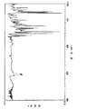
前記素子A、B、CのELスペクトルを図9に示す。これにより発光層の膜厚と電子輸送層の膜厚の変化が色と輝度にどのような影響を与えているかがわかる。参考として、BCzVBi溶液(chloroform、1.0×10⁻⁵mol/L)の励起・蛍光スペクトルおよびDATT溶液(chloroform、1.0×10−5mol/L)、薄膜の蛍光スペクトルを図10に示す。図10中、BCzVBi Ex.は励起スペクトルであり、BCzVBi Em.、DATT sol.、DATT filmはいずれも蛍光スペクトルである。
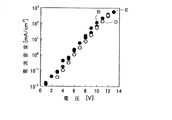
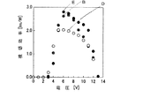
素子A、B、Cのもつ輝度−電圧、電流密度−電圧、輝度−電流密度、視感効率−電圧、電流効率−電圧特性を図11〜15に示す。
図中、素子Aは黒丸、素子Bは白丸、素子Cは灰色丸で示す。
【0023】
比較例1
素子構造が〔ITO(1300Å)/α−NPD(400Å)/DATT(400Å)/Alq3(200Å)/LiF(5Å)/Al(1000Å)〕であるノンドープ素子(イ)を比較例とし、素子A、B、Cと同様の特性を測定し、図11〜15に◇印により表示した。
【0024】
素子A、B、Cおよび前記比較例素子(イ)のEL特性を下記表に示す。
【表2】
素子A、B、Cから得られたEL素子スペクトルは、いずれも450nmにサブピーク、470nmに主ピークを有するBCzVBiに由来する青色発光が観測された。素子Aについては、電子輸送層にDATTを用いているため、発光開始電圧が9Vと他の素子に比べて高いけれども、高電圧(15V以上)をかけても素子が破壊されることなく、安定である。素子B、Cとノンドープ素子(イ)(比較例)を比較すると、CIE色度座標において色純度が改善され、素子特性においても素子B、Cの方が最高輝度、最大電流効率、最大外部量子効率においていずれも3倍以上高い値を示した。
比較例1のノンドープ素子において、無放射失活過程で緩和していた再結合エネルギーが、BCzVBiをドープすることにより蛍光として得ることができたためであると考えられる。
素子Cでは、電子輸送層をAlq3から電子輸送性ホールブロック層として知られているBCPに置き換えた素子を作製した。この素子は、DATT層で生成した励起子をブロックする、またはDATT層にホールを閉じ込め、さらなる特性かつ色純度の向上をねらい作製した。しかし、作製した素子の特性は素子Bに比べ最高輝度、最大外部量子効率等は同等の値を示すものの、駆動電圧が高くなってしまった。これは、BCPに比べAlq3の方が陰極からの電子の注入が容易であるためと考えられる。
これまでDATTをホスト材料として素子作製してきたが、これら結果より、素子Bが最も優れた特性を示した。このため、さらなる特性の向上を目指し発光層の膜圧、BCzVBiのドープ濃度の最適化を行った。
【0026】
参考例3
前記特性向上のためにテストした素子(3種)の構造を図16に示す。
1番目(素子D)は発光層の膜厚400Å、ドープされた層の膜厚200Å
2番目(素子E)は発光層の膜厚300Å、ドープされた層の膜厚300Å
3番目(素子Bと同一)は発光層の膜厚200Å、ドープされた層の膜厚400Åとした。
素子D:ITO(1300Å)/α−NPD(400Å)/BCzVBi〔7wt%〕doped DATT(200Å)/Alq3(400Å)/LiF(5Å)/Al(1000Å)}
素子E:ITO(1300Å)/α−NPD(400Å)/BCzVBi〔7wt%〕doped DATT(300Å)/Alq3(300Å)/LiF(5Å)/Al(1000Å)}
素子B:ITO(1300Å)/α−NPD(400Å)/BCzVBi〔7wt%〕doped DATT(400Å)/Alq3(200Å)/LiF(5Å)/Al(1000Å)}
素子D、EおよびBのELスペクトルを図17に示し、輝度−電圧、電流密度−電圧、輝度−電流密度、視感効率−電圧、電流効率−電圧特性を図18〜22に示す。下記表にこれら特性をまとめたものを示す。
図中、白丸は素子D、黒丸は素子E、灰色の丸は素子Bを示す。
【表3】
素子DとEの特性を素子B{ITO/α−NPD(400Å)/BCzVBi〔7wt%〕dopedDATT(400Å)/Alq3(200Å)/LiF(5Å)/Al(1000Å)}と対比しながら、図18〜22および前記表3に示した。図中、素子Bは灰色丸で示す。
【0028】
素子Dから得られたELスペクトルは、470nmに主ピークを有し、500nm付近に大きな肩を持つ水色発光が観測された。これは、発光層(DATTを7wt%ドープしたBCzVBi層)が200Åと薄くなることにより、発光領域がAlq3層にまで広がり、発光したためであると考えられる。素子Eから得られたELスペクトルは、450nmにサブピーク、470nmに主ピークを有するBCzVBiに由来する青色発光が観測された。素子特性は、発光領域がAlq3層まで広がった素子Dは素子Bに比べて下回るものであった。しかし、素子Eでは最高輝度で約40%、最大外部量子効率においては約15%ほど高い値を示した。これは、キャリアバランスの向上に起因するものと考えられる。この結果より、発光層の最適膜厚は300Åであることが判る。
【0029】
参考例4
最適のドープ濃度を求めて、図23に示す構造の素子を作った。
ドープ濃度3wt%の素子を素子F
ドープ濃度7wt%の素子を素子E(前記素子Eと同一)
ドープ濃度10wt%の素子を素子G
とした。
素子FとGから得られたELスペクトルを図24に示し、輝度−電圧、電流密度−電圧、輝度−電流密度、視感効率−電圧、電流効率−電圧特性を図25〜29に示す。下記表にこれら特性をまとめたものを示す。
【0030】
【表4】
素子F、Gから得られたELスペクトルは、いずれも450nmにサブピーク、470nmに主ピークを有するBCzVBiに由来する青色系発光が観測された。素子特性は、素子F、G両者とも素子Eを下回るものであった。素子Gでは、450nmのサブピークが小さくなり、ややブロードになっていることから濃度消光が起きていると考えられる。この結果よりDATTにおけるBCzVBiの最適ドープ濃度は7wt%であることがわかった。
つぎに、この最適化したBCzVBiドープ型素子:素子Eにおいて、青色ホスト材料として知られているDPVBiと比較する。
【0032】
比較例2
青色ホスト材料として公知の下記式、
【化11】
【0033】
前記有機EL素子(ロ)と本発明の有機EL素子E{ITO(1300Å)/α−NPD(400Å)/BCzVBi〔7wt%DATTドープ〕(300Å)/Alq3(300Å)/LiF(5Å)/Al(1000Å)}を対比し、DATTとDPVBiの電気特性を調べた結果を下記表に示す。
【0034】
【表5】
素子Eと素子(ロ)のそれぞれのELスペクトルを図31に、輝度−電圧特性を図32に、電流密度−電圧特性を図33に、輝度−電流密度特性を図34に、発光効率−電圧特性を図35に電流効率−電圧特性を図36に示す。
【0036】
さらに、素子Eと素子(ロ)のEL特性を下記表に示す。
【表6】
これらのデータからみると、素子Eの方が素子(ロ)より発光効率−電圧特性、電流効率−電圧特性、最大外部量子効率の点で優れており、とくに最大外部量子効率で30%以上優れていることが分る。これはDPVBiのガラス転移温度が63.6℃と低く、高電圧下において安定な膜状態を維持できないためと考えられる。
【0038】
参考例化合物の1つであるDATTは、従来公知のホスト材料であるDPVBiに充分対抗できる材料であり、ホスト材料としての選択範囲を拡大することができた。図37には、BCzVBiの励起、蛍光スペクトルおよびDPVBi溶液のPLスペクトル、DATT溶液のPLスペクトルを示す。BCzVBiが発光するメカニズムは、ホストのDPVBiあるいはDATTがそれぞれ特有の励起波長によって蛍光を発し、その蛍光がBCzVBiの励起光となってBCzVBiが蛍光スペクトルを発する。したがってホスト材料の蛍光スペクトルの位置とゲスト材料の励起スペクトルの位置の重なりが大きい方がエネルギー移動量が大きくなり、ホスト材料とゲスト材料の組み合わせが良いということになる。この点から図37の注目点は、BCzVBiの励起スペクトル曲線とDATT溶液の蛍光スペクトルの重なり具合ということになる。図38には、DATTフィルム(λex=394nm,λem=448nm)とDATTをドープしたBCzVBiフィルム(λex=394nm,λem=474nm)のPLスペクトルを示し、図39にはDPVBiフィルム(λex=348nm,λem=461nm)とDPVBiをドープしたBCzVBiフィルム(λex=348nm,λem=474nm)のPLスペクトルを示す、これにより素子Eも素子(ロ)も共にエネルギー移動が主な発光機構であることが分る。以上の点を総合すると本発明のDATTは、熱安定性に優れ、長寿命青色発光素子の形成材料として有用であるこ。とくにDATTはDPVBiと比較すると、BCzVBiドープ型素子において約35%もの高効率化を達成でき、青色ホスト材料として有用であることが分る。
【0039】
実施例1{4,4″−N,N′−ジカルバゾール−3′,4′,5′,6′−テトラフェニル−p−ターフェニル〔4,4″−N,N′−Dicarbazole−3′,4′,5′,6′−tetraphenyle−p−terphenyle(CzTT)〕}の合成
【化12】
【0040】
【表7】
1H−NMR(270MHz,CDCl3,TMS):δ(ppm)=7.05〜7.20(28H,aromatic ring),7.31〜7.31,7.43〜7.50,8.17〜8.22(16H,carbazoleunit)
【0041】
実施例2〔ジフェニルアミン含有 ヘキサフェニルベンゼン誘導体(TATT)の合成〕
【化13】
【0042】
【表8】
1H−NMR(270MHz,CDCl3,TMS):δ(ppm)=6.58〜6.72,6.80〜6.86,6.88〜7.00,7.12〜7.20(6H,6H,28H,8H,aromatic ring),
【0043】
参考例5〔ゲスト色素としてクマリン545T(C545T:緑)を用いた素子の作成〕
図46〜48に作成した素子J、K、Lの素子構造を示す。また、DATTおよびC545Tの電気化学特性を表9に示す。
【0044】
【表9】
素子J:ITO(1300Å)/α−NPD(500Å)/C545T〔1wt%〕doped DATT(200Å)/DATT(300Å)/LiF(5Å)/Al(1000Å)}
素子K:ITO(1300Å)/α−NPD(400Å)/C545T〔1wt%〕doped DATT(400Å)/Alq3(200Å)/LiF(5Å)/Al(1000Å)}
素子L:ITO(1300Å)/α−NPD(400Å)/C545T〔1wt%〕doped Alq3(400Å)/Alq3(200Å)/LiF(5Å)/Al(1000Å)}
比較として、
ノンドープ素子(ハ):ITO(1300Å)/α−NPD(400Å)/DATT(400Å)/Alq3(200Å)/LiF(5Å)/Al(1000Å)}より得られたELスペクトルを図49に示す。参考としてC545T溶液(クロロホルム 1.0×10⁻⁵[mol/L])の励起・蛍光スペクトルおよびDATT溶液(クロロホルム 1.0×10⁻⁵[mol/L])、薄膜の蛍光スペクトルを図50に示す。輝度−電圧、電流密度−電圧、輝度−電流密度、視感効率−電圧、電流効率−電圧特性を図51〜55に示す。表10にこれら特性をまとめたものを示す。
図中、素子Lは黒丸、素子Jは白丸、素子Kは灰色丸、ノンドープ素子(ハ)は◇印で示す。
【0046】
【表10】
素子J、Kより得られたELスペクトル(図49)は、それぞれ500nm、520nmにピークを有するC545Tに由来する緑色発光が観測された。素子J、Kから得られたELスペクトルは450nm付近に肩を有していた。これは、ホスト材料であるDATTからの発光ではないかと推測される。C545Tドープ型素子の発光機構がエネルギー移動型と仮定すると、ホストからのエネルギー移動がゲストであるC545Tに十分起こらず、ホスト材料の発光も観測されたと考えられる。また素子Kとノンドープ素子(ハ)を比較すると、素子Kの方が最大外部量子効率において約2倍近い値を示した。これは、ノンドープ素子(ハ)において、無放射失活過程で緩和していた再結合エネルギーが、C545Tをドープすることにより蛍光として得ることができたためと考えられる。ここでは、素子Kとノンドープ素子(ハ)において発光色の違いにより、輝度、視感効率などの考察は行わない。
また、素子Kに比べ素子Lの方が視感効率、最大外部量子効率において約3倍以上高い値を示した。これはDATTよりAlq3の方がキャリア輸送性に優れ、かつC545Tにエネルギー移動しやすいためであると考えられる。
【0048】
【発明の効果】
(1)本発明により緑色から青色にわたるいろいろの色素用ホスト材料として有用な新規化合物を提供することができた。
(2)本発明化合物は、しばしば用いられている青色色素を色どりよく発光させるとともに、耐熱性がよく、350℃を越える温度でも分解することがなく、安定であるため、すぐれたエレクトロルミネッセンス素子を提供できる。
【図面の簡単な説明】
【図1】 2−(9−アンスリル)−4,4,5,5−テトラメチル−1,3,2−ジオキサボロン(DOB−Anth)の1H−NMRスペクトルを示す
【図2】 2−(9−アンスリル)−4,4,5,5−テトラメチル−1,3,2−ジオキサボロン(DOB−Anth)のIRスペクトルを示す
【図3】 2−(9−アンスリル)−4,4,5,5−テトラメチル−1,3,2−ジオキサボロン(DOB−Anth)のMASSスペクトルを示す
【図4】 4,4″−ジ−(9−アンスリル)−3′,4′,5′,6′−テトラフェニル−p−ターフェニル(DATT)の1H−NMRスペクトルを示す
【図5】 図4の部分拡大図である。
【図6】 4,4″−ジ−(9−アンスリル)−3′,4′,5′,6′−テトラフェニル−p−ターフェニル(DATT)のIRスペクトルを示す
【図7】 参考例2で用いたエレクトロルミネッセンス素子Aの積層構造を示す。なお、図中、ELTは電子輸送層、EMLは電子移動層、HTLはホール輸送層を示す。
【図8】 参考例2で用いたエレクトロルミネッセンス素子Bの積層構造を示す。なお、図中、ELTは電子輸送層、EMLは電子移動層、HTLはホール輸送層を示す。
【図9】 素子A、B、Cの各エレクロトロルミネッセンススペクトルを示す。
【図10】 参考例1で得られた4,4″−ジ−(9−アンスリル)−3′,4′,5′,6′−テトラフェニル−p−ターフェニル(DATT)の溶液とフィルムおよびゲスト色素のジスチリルアミン誘導体(BCzVBi:青色色素)の溶液に関する励起・蛍光スペクトルを示す。
【図11】 前記素子A、B、Cおよび比較例の素子(イ)のそれぞれの輝度−電圧特性を示すグラフである。
【図12】 前記素子A、B、Cおよび比較例の素子(イ)のそれぞれの電流密度−電圧特性を示すグラフである。
【図13】 前記素子A、B、Cおよび比較例の素子(イ)のそれぞれの輝度−電流密度特性を示すグラフである。
【図14】 前記素子A、B、Cおよび比較例の素子(イ)のそれぞれの視感効率−電圧特性を示すグラフである。
【図15】 前記素子A、B、Cおよび比較例の素子(イ)のそれぞれの電流効率−電圧特性を示すグラフである。
【図16】 参考例3に用いたエレクトロルミネッセンス素子の積層構造を示す。なお、図中、ELTは電子輸送層、EMLは電子移動層、HTLはホール輸送層を示す。
【図17】 エレクトロルミネッセンス素子B、D、EそれぞれのELスペクトルを示す。
【図18】 エレクトロルミネッセンス素子B、D、Eそれぞれの輝度−電圧特性を示す。
【図19】 エレクトロルミネッセンス素子B、D、Eそれぞれの電流密度−電圧特性を示す。
【図20】 エレクトロルミネッセンス素子B、D、Eそれぞれの輝度−電流密度特性を示す。
【図21】 エレクトロルミネッセンス素子B、D、Eそれぞれの視感効率−電圧特性を示す。
【図22】 エレクトロルミネッセンス素子B、D、Eそれぞれの電流効率−電圧特性を示す。
【図23】 参考例4のエレクトロルミネッセンス素子の積層構造を示す。なお、図中、ELTは電子輸送層、EMLは電子移動層、HTLはホール輸送層を示す。
【図24】 エレクトロルミネッセンス素子E、F、Gおよび本発明のDATTをドープしなかった素子のそれぞれのELスペクトルを示す。
【図25】 エレクトロルミネッセンス素子E、F、Gのそれぞれの輝度−電圧特性を示す。
【図26】 エレクトロルミネッセンス素子E、F、Gのそれぞれの電流密度−電圧特性を示す。
【図27】 エレクトロルミネッセンス素子E、F、Gのそれぞれの輝度−電流密度特性を示す。
【図28】 エレクトロルミネッセンス素子E、F、Gのそれぞれの視感効率−電圧特性を示す。
【図29】 エレクトロルミネッセンス素子E、F、Gのそれぞれの電流効率−電圧特性を示す。
【図30】 比較例2の有機EL素子(ロ)の構成を示す。
【図31】 素子Eと素子(ロ)のそれぞれのELスペクトルを示す。
【図32】 素子Eと素子(ロ)のそれぞれの輝度−電圧特性を示すグラフである。
【図33】 素子Eと素子(ロ)のそれぞれの電流密度−電圧特性を示すグラフである。
【図34】 素子Eと素子(ロ)のそれぞれの輝度−電流密度特性を示すグラフである。
【図35】 素子Eと素子(ロ)のそれぞれの発光効率−電圧特性を示すグラフである。
【図36】 素子Eと素子(ロ)のそれぞれの電流効率−電圧特性を示すグラフである。
【図37】 BCzVBiの励起、蛍光スペクトルおよびDPVBi溶液のPLスペクトル、DATT溶液のPLスペクトルを示す。
【図38】 DATTフィルムとDATTをドープしたBCzVBiフィルムのPLスペクトルを示す。
【図39】 DPVBiフィルムとDPVBiをドープしたBCzVBiフィルムのPLスペクトルを示す。
【図40】 4,4″−N−N′−ジ−カルバゾール−3′,4′,5′,6′−テトラフェニル−p−ターフェニル(CzTT)の1H−NMRスペクトルを示す。
【図41】 4,4″−N−N′−ジ−カルバゾール−3′,4′,5′,6′−テトラフェニル−p−ターフェニル(CzTT)のIRスペクトルを示す。
【図42】 4,4″−N−N′−ジ−カルバゾール−3′,4′,5′,6′−テトラフェニル−p−ターフェニル(CzTT)のMASSスペクトルを示す。
【図43】 ジフェニルアミン含有ヘキサフェニルベンゼン誘導体(TATT)の1H−NMRスペクトルを示す。
【図44】 ジフェニルアミン含有ヘキサフェニルベンゼン誘導体(TATT)のIRスペクトルを示す。
【図45】 ジフェニルアミン含有ヘキサフェニルベンゼン誘導体(TATT)のMASSスペクトルを示す。
【図46】 素子Jの積層構造を示す断面図である。
【図47】 素子Kの積層構造を示す断面図である。
【図48】 素子Lの積層構造を示す断面図である。
【図49】 素子J、K、Lおよびドープをしていない素子(ハ)の規格化強度および波長との関係を示すグラフである。
【図50】 ゲスト色素クマリン545Tの励起スペクトル(Ex)と蛍光スペクトル(Em)および4,4″−ジ−9−アンスリル−3′,4′,5′,6′−テトラフェニル−p−ターフェニル(DATT)の溶液とフィルムのPLスペクトルを示す。
【図51】 前記素子J、K、Lおよびドープしていない素子(ハ)のそれぞれの輝度−電圧特性を示すグラフである。
【図52】 前記素子J、K、Lおよびドープしていない素子(ハ)のそれぞれの電流密度−電圧特性を示すグラフである。
【図53】 前記素子J、K、Lおよびドープしていない素子(ハ)のそれぞれの輝度−電流密度特性を示すグラフである。
【図54】 前記素子J、K、Lおよびドープしていない素子(ハ)のそれぞれの視感効率−電圧特性を示すグラフである。
【図55】 前記素子J、K、Lおよびドープしていない素子(ハ)のそれぞれの電流効率−電圧特性を示すグラフである。[0001]
BACKGROUND OF THE INVENTION
The present invention relates to
[0002]
[Prior art]
Conventionally, a host material corresponding to a blue dye has a wavelength of blue fluorescence of a guest on the short wavelength side of 440 to 450 nm, so bis (2-methyl-8-hydroxyquinolinolato) -4-phenylphenoxyaluminum Complex (BAlq2) And 4- (2,2-diphenylvinyl) -1- [4- (2,2-diphenylvinyl) phenyl] benzene (DPVBi) are limited, and development of a new blue host material is required. It was done.
[0003]
[Problems to be solved by the invention]
An object of the present invention is to develop a new compound useful as a host material for various dyes ranging from green to blue, in order to measure the enrichment of the host material with respect to the blue dyes of electroluminescence devices commonly used today.
[0004]
[Means for Solving the Problems]
The first of the present invention is the following general formula (1)
[2]
And 4,4 ″ -di- (aryl) -3 ′, 4 ′, 5 ′, 6′-tetraphenyl-p-terphenyl derivatives represented by
The second of the present invention isClaim 1The present invention relates to a host material containing a 4,4 ″ -di- (aryl) -3 ′, 4 ′, 5 ′, 6′-tetraphenyl-p-terphenyl derivative.
The third aspect of the present invention isClaim 1The present invention relates to an electroluminescence (EL) device having a layer containing a 4,4 ″ -di- (aryl) -3 ′, 4 ′, 5 ′, 6′-tetraphenyl-p-terphenyl derivative.
[0005]
In the present inventionR 1 ~ R 28 And R 48 ~ R 57 The alkyl group in is not particularly limited, but is usually a linear or branched alkyl group having 1 to 20 carbon atoms, particularly preferably a linear or branched alkyl group having 1 to 6 carbon atoms.
In the present inventionR 1 ~ R 28 And R 48 ~ R 57 The alkoxy group in is a form in which the alkyl group is bonded to an oxygen atom.
In the present inventionR 1 ~ R 28 And R 48 ~ R 57 The alkylamino group in is a type in which part or all of the hydrogen of the amino group is substituted with the alkyl group.
In the present inventionR 1 ~ R 28 And R 48 ~ R 57 The aryl group in is one having one benzene ring (phenyl group), one having 2 to 8 integrated rings (for example, naphthyl group, anthranyl group), or a hydroxyl group or the alkyl group as necessary. , An alkoxyl group, an alkylamino group, an amino group, a halogen, a cyano group, a nitro group, a carboxyl group, an alkoxycarbonyl group and the like may be used as a substituent.
In the present inventionR 1 ~ R 28 And R 48 ~ R 57 In the aralkyl group, the aryl part may be the same as the aryl group, and the alkylene part may be a linear or branched alkylene, and usually has 1 to 20 carbon atoms, preferably 1 to 6 carbon atoms. It is.
In the present inventionR 1 ~ R 28 And R 48 ~ R 57 The alkoxycarbonyl group in can have the same alkyl moiety as the alkyl group.
In the present inventionR 1 ~ R 28 And R 48 ~ R 57 The aryloxycarbonyl group in can have the aryl moiety the same as the aryl group.
The 3- to 8-membered carbocycle may be aliphatic, but is preferably an aromatic group, and a 3-membered or 6-membered ring is preferable among the 3- to 8-membered rings. In addition,R 1 ~ R 28 And R 48 ~ R 57 As for, hydrogen is most preferable, and a dimethylamino group is preferred as the next preferable one.R 1 ~ R 28 And R 48 ~ R 57 Among these, it is relatively preferable that there is a group other than hydrogen.R 1 ~ R 20 Is.
[0006]
The compound of the present invention can be produced by the following method. That is, the following general formula (2)
[Chemical 3]
4,4 ″ -dihalogeno-2 ′, 3 ′, 5 ′, 6′-tetraphenyl-p-terphenyl derivatives represented by the general formula (3)
[4]
Indicated byN, N'-Reacting with diarylamineBy the present invention4,4 "-di- (aryl) -3 ', 4', 5 ', 6'-tetraphenyl-p-terphenyl derivativeCan be manufactured.
[0007]
Also,Specific examples of the compound of the present invention include
4,4 "-di- (N, N-diphenylamino) -3 ', 4', 5 ', 6'-tetraphenyl-p-terphenyl,
4,4 "-di- [N- (1-naphthyl) -N-phenylamino] -3 ', 4', 5 ', 6'-tetraphenyl-p-terphenyl,
4,4 "-di- [N- (2-naphthyl) -N-phenylamino] -3 ', 4', 5 ', 6'-tetraphenyl-p-terphenyl,
4,4 "-di- [N- (p-toluyl) -N-phenylamino] -3 ', 4', 5 ', 6'-tetraphenyl-p-terphenyl,
4,4 "-di- [N- (m-toluyl) -N-phenylamino] -3 ', 4', 5 ', 6'-tetraphenyl-p-terphenyl,
4,4 "-di- [N- (o-toluyl) -N-phenylamino] -3 ', 4', 5 ', 6'-tetraphenyl-p-terphenyl,
4,4 "-di- [N- (m-xylyl) -N-phenylamino] -3 ', 4', 5 ', 6'-tetraphenyl-p-terphenyl,
4,4 "-di- [N- (o-xylyl) -N-phenylamino] -3 ', 4', 5 ', 6'-tetraphenyl-p-terphenyl,
4,4 "-di- [N- (o-chlorophenyl) -N-phenylamino] -3 ', 4', 5 ', 6'-tetraphenyl-p-terphenyl,
4,4 "-di- [N- (m-chlorophenyl) -N-phenylamino] -3 ', 4', 5 ', 6'-tetraphenyl-p-terphenyl,
4,4 "-di- [N- (p-chlorophenyl) -N-phenylamino] -3 ', 4', 5 ', 6'-tetraphenyl-p-terphenyl,
4,4 "-di- [N- (o-dichlorophenyl) -N-phenylamino] -3 ', 4', 5 ', 6'-tetraphenyl-p-terphenyl,
4,4 "-di- [N- (m-dichlorophenyl) -N-phenylamino] -3 ', 4', 5 ', 6'-tetraphenyl-p-terphenyl,
4,4 "-di- [N- (o-methoxyphenyl) -N-phenylamino] -3 ', 4', 5 ', 6'-tetraphenyl-p-terphenyl,
4,4 "-di- [N- (m-methoxyphenyl) -N-phenylamino] -3 ', 4', 5 ', 6'-tetraphenyl-p-terphenyl,
4,4 "-di- [N- (p-methoxyphenyl) -N-phenylamino] -3 ', 4', 5 ', 6'-tetraphenyl-p-terphenyl,
4,4 "-di- [N- (1-anthranyl) -N-phenylamino] -3 ', 4', 5 ', 6'-tetraphenyl-p-terphenyl,
4,4 "-di- [N- (2-anthranyl) -N-phenylamino] -3 ', 4', 5 ', 6'-tetraphenyl-p-terphenyl,
4,4 "-di- [N- (9-anthranyl) -N-phenylamino] -3 ', 4', 5 ', 6'-tetraphenyl-p-terphenyl,
4,4 "-di- [N- (1-phenanthrenyl) -N-phenylamino] -3 ', 4', 5 ', 6'-tetraphenyl-p-terphenyl,
4,4 "-di- [N- (2-fluorenyl) -N-phenylamino] -3 ', 4', 5 ', 6'-tetraphenyl-p-terphenyl,
4,4 "-di- [N- (9-fluorenyl) -N-phenylamino] -3 ', 4', 5 ', 6'-tetraphenyl-p-terphenyl,
4,4 "-di- [N- (2-pyridyl) -N-phenylamino] -3 ', 4', 5 ', 6'-tetraphenyl-p-terphenyl,
4,4 "-di- [N- (2-quinolyl) -N-phenylamino] -3 ', 4', 5 ', 6'-tetraphenyl-p-terphenyl,
4,4 "-di- [N- (9-acridinyl) -N-phenylamino] -3 ', 4', 5 ', 6'-tetraphenyl-p-terphenyl,
4,4 "-di- [N- (2-thiophenyl) -N-phenylamino] -3 ', 4', 5 ', 6'-tetraphenyl-p-terphenyl,
4,4 "-di- [N- (2-furanyl) -N-phenylamino] -3 ', 4', 5 ', 6'-tetraphenyl-p-terphenyl,
Etc.
[0008]
General formula (2Specific examples of 4,4 ″ -dihalogeno-2 ′, 3 ′, 5 ′, 6′-tetraphenyl-p-terphenyl derivatives represented by
4,4 "-di-chloro-3 ', 4', 5 ', 6'-tetraphenyl-p-terphenyl,
4,4 "-di-bromo-3 ', 4', 5 ', 6'-tetraphenyl-p-terphenyl,
4,4 "-di-iodo-3 ', 4', 5 ', 6'-tetraphenyl-p-terphenyl,
3,3 "-dimethyl-4,4" -di-chloro-3 ', 4', 5 ', 6'-tetraphenyl-p-terphenyl
3,3 "-dimethyl-4,4" -di-bromo-3 ', 4', 5 ', 6'-tetraphenyl-p-terphenyl
3,3 "-dimethyl-4,4" -di-iodo-3 ', 4', 5 ', 6'-tetraphenyl-p-terphenyl
Etc.
[0009]
General formula (3Specific examples of N, N-diarylamines represented by) are N, N-diphenylamine, N- (1-naphthyl) -N-phenylamine, N- (2-naphthyl) -N-phenylamine, N— (P-toluyl) -N-phenylamine, N- (m-toluyl) -N-phenylamine, N- (o-toluyl) -N-phenylamine, N- (m-xylyl) -N-phenylamine, N- (o-xylyl) -N-phenylamine, N- (m-chlorophenyl) -N-phenylamine, N- (p-chlorophenyl) -N-phenylamine, N- (o-chlorophenyl) -N-phenyl Amine, N- (o-dichlorophenyl) -N-phenylamine, N- (m-dichlorophenyl) -N-phenylamine, N- (o-methoxyphenyl) -N-phenylamine N- (m-methoxyphenyl) -N-phenylamine, N- (p-methoxyphenyl) -N-phenylamine, N- (1-anthranyl) -N-phenylamine, N- (2-anthranyl) -N -Phenylamine, N- (9-anthranyl) -N-phenylamine, N- (1-phenanthrenyl) -N-phenylamine, N- (2-fluorenyl) -N-phenylamine, N- (9-phenanthrenyl) -N-phenylamine, N- (1-fluorenyl) -N-phenylamine, N- (2-fluorenyl) -N-phenylamine, N- (9-fluorenyl) -N-phenylamine, N- (2- Pyridyl) -N-phenylamine, N- (2-quinolyl) -N-phenylamine, N- (9-acridinyl) -N-phenylamine, N- (2-thi Phenyl) -N- phenylamine, N-(2-furanyl) -N- phenylamine, and the like.
[0010]
Of the compound of the present inventionAs a reaction catalyst used in the production method, a trialkylphosphine and organic palladium are generally used in combination, and a combination of tri-tert-butylphosphine and palladium acetate is particularly preferable. The reaction solvent is not particularly limited as long as it is inert to the reaction components, but aromatic hydrocarbons such as toluene and xylene can be usually used. Regarding the reaction temperature, a range from room temperature to the reflux temperature can be used, but the reaction is preferably carried out at the reflux temperature in consideration of the reaction time.
[0011]
When an organic EL device is produced using the compound of the present invention, since the compound of the present invention is usually used as a host material for various guest dyes, other than this feature point There are no special restrictions.
Examples that can be preferably used as guest dyes in the present invention include distyrylamine derivatives (BCzVBi: blue), tetraphenylbutadiene (blue), perylene (blue), 9,10-diphenylanthracene (blue), azomethine sulfite complex ( Blue).
[0012]
Therefore, there is no particular limitation on the structure of the EL element, but BCzVBi is used as a host material as a guest dye.referencePreferred device configuration when using 4,4 ″ -di- (9-anthryl) -3 ′, 4 ′, 5 ′, 6′-tetraphenyl-p-terphenyl (DATT) obtained in Example 1 Three examples are shown below.
[0013]
Anode / α-NPD / BCzVBi doped DATT (light emitting layer) / DATT (electron transport layer) / LiF (electron injection layer) / cathode
Anode / α-NPD / BCzVBi doped DATT (light emitting layer) / Alq3(Electron transport layer) / LiF (electron injection layer) / cathode
Anode / α-NPD / BCzVBi doped DATT (light emitting layer) / BCP (electron transport layer) / LiF (electron injection layer) / cathode
[0014]
【Example】
Hereinafter, the present invention will be described with reference to examples, but the present invention is not limited thereto.
[0015]
Synthesis example 1
Synthesis of 1,3-bis (p-bromophenyl) -2-propanone [1,3-bis (p-bromophenyl) -2-propanone] (BBPP)
[5]
[0016]
Synthesis example 2
Synthesis of 2,5-bis (p-bromophenyl) -3,4-diphenylcyclopentadienone [2,5-bis (p-bromophenyl) -3,4-diphenylcyclopentadiene] (BB-4PK)
[6]
[0017]
(1) Synthesis of 4,4 ″ -dibromo-3 ′, 4 ′, 5 ′, 6′-tetraphenyl-p-terphenyl (DTT)
[7]
[0018]
(2) Synthesis of 2- (9-anthryl) -4,4,5,5-tetramethyl-1,3,2-dioxaboron (DOB-Anth)
[8]
[0019]
(3) 4,4 "-di- (9-anthryl) -3 ', 4', 5 ', 6'-tetraphenyl-p-terphenyl [4,4" -Di- (9-anthryl) -3 ', 4', 5 ', 6'-tetraphenyl-p-terphenyl] (DATT)
[Chemical formula 9]
[0020]
EL element using distyrylamine derivative (BCzVBi: blue) as guest dye
FIG. 7 (element A), FIG. 8 [Tris (8-hydroxyquinolinolato) aluminum (complex) (Alq as an electron transport layer (ETL))3) Was used, and three elements A, B, and C shown in FIG. 3 were prepared. The element in the case where BCP was used as the electron transport layer (ETL) was defined as C.
The element A in FIG. 7 is obtained by vacuum-depositing α-NPD, which is a hole transport material, as a hole transport layer (HTL) on an ITO glass electrode by 500Å and BCzVBi in which 7 wt% of DATT is co-deposited as an emission layer (EML). Then, DATT is deposited in a thickness of 300 mm as an electron transport layer (ELT), lithium fluoride is deposited in a thickness of 5 mm as an electron injection layer, and finally Al metal is deposited in a thickness of 1000 mm as a back electrode. It was created by vapor deposition with a thickness.
That is, the configuration of the element A is as follows.
[ITO (1300Å) / α-NPD (500Å) / BCzVBi [7wt%] doped DATT (200Å) / DATT (300Å) / LiF (5Å) / Al (1000Å)]
In the device B or C of FIG. 8, α-NPD as a hole transport material was vacuum-deposited as a hole transport layer (HTL) on an ITO glass electrode by 400Å vacuum, and 7 wt% of DATT was co-deposited as an emission layer (EML). BCzVBi is laminated with a thickness of 400 mm, and then Alq is used as an electron transport layer (ETL).3Alternatively, BCP is vapor-deposited with a thickness of 200 mm, lithium fluoride is vapor-deposited with a thickness of 5 mm as an electron injection layer, and finally Al metal is vapor-deposited with a thickness of 1000 mm as a back electrode.
That is, the configurations of the elements B and C are as follows.
Element B [ITO (1300 Å) / α-NPD (400 Å) / BCzVBi [7 wt%] doped DATT (400 Å) / Alq3(200Å) / LiF (5Å) / Al (1000Å)]
Element C [ITO (1300 mm) / α-NPD (400 mm) / BCzVBi [7 wt%] doped DATT (400 mm) / BCP (200 mm) / LiF (5 mm) / Al (1000 mm)]
Alq3, BCP, BCzVBi are represented by the following equations.
[10]
The electrochemical properties of DATT, BCP and BCzVBi are as shown in the following table.
[Table 1]
The EL spectra of the elements A, B, and C are shown in FIG. As a result, it can be seen how changes in the thickness of the light emitting layer and the thickness of the electron transport layer affect the color and the luminance. As a reference, BCzVBi solution (chloroform, 1.0 × 10⁻⁵mol / L) excitation / fluorescence spectrum and DATT solution (chloroform, 1.0 × 10⁻⁵mol / L), and the fluorescence spectrum of the thin film is shown in FIG. In FIG. 10, BCzVBi Ex. Is the excitation spectrum, BCzVBi Em. , DATT sol. , DATT film are fluorescence spectra.
The luminance-voltage, current density-voltage, luminance-current density, luminous efficiency-voltage, and current efficiency-voltage characteristics of the elements A, B, and C are shown in FIGS.
In the figure, element A is indicated by a black circle, element B is indicated by a white circle, and element C is indicated by a gray circle.
[0023]
Comparative Example 1
The element structure is [ITO (1300Å) / α-NPD (400Å) / DATT (400Å) / Alq.3(200 Å) / LiF (5 Å) / Al (1000 と し)] was used as a comparative example, and the same characteristics as the devices A, B, and C were measured and displayed in FIGS. .
[0024]
The EL characteristics of the elements A, B, C and the comparative element (A) are shown in the following table.
[Table 2]
In the EL element spectra obtained from the elements A, B, and C, blue emission derived from BCzVBi having a sub peak at 450 nm and a main peak at 470 nm was observed. For element A, since DATT is used for the electron transport layer, the light emission starting voltage is 9 V, which is higher than that of other elements. However, even when a high voltage (15 V or more) is applied, the element is not destroyed and stable. It is. Comparing the elements B and C with the non-doped element (a) (comparative example), the color purity is improved in the CIE chromaticity coordinates, and the element characteristics of the elements B and C are the highest luminance, the maximum current efficiency, and the maximum external quantum. All of the efficiency values were three times higher.
In the non-doped element of Comparative Example 1, it is considered that the recombination energy relaxed in the non-radiation deactivation process could be obtained as fluorescence by doping BCzVBi.
In device C, the electron transport layer is made of Alq.3Thus, a device replaced with BCP known as an electron transporting hole blocking layer was produced. This device was fabricated for blocking excitons generated in the DATT layer or confining holes in the DATT layer to further improve the characteristics and color purity. However, the characteristics of the manufactured device were higher than those of the device B, but the driving voltage was high although the maximum luminance, the maximum external quantum efficiency, and the like showed the same values. This is Alq compared to BCP3This is probably because electrons are more easily injected from the cathode.
So far, devices have been manufactured using DATT as a host material. From these results, device B showed the most excellent characteristics. Therefore, the film pressure of the light emitting layer and the doping concentration of BCzVBi were optimized with the aim of further improving the characteristics.
[0026]
FIG. 16 shows the structures of the elements (three types) tested for improving the characteristics.
The first (device D) has a light emitting layer thickness of 400 mm and a doped layer thickness of 200 mm.
The second (element E) has a light emitting layer thickness of 300 mm and a doped layer thickness of 300 mm.
The third layer (same as the element B) has a light emitting layer thickness of 200 mm and a doped layer thickness of 400 mm.
Element D: ITO (1300Å) / α-NPD (400Å) / BCzVBi [7 wt%] doped DATT (200Å) / Alq3(400?) / LiF (5?) / Al (1000?)}
Element E: ITO (1300 Å) / α-NPD (400 Å) / BCzVBi [7 wt%] doped DATT (300 Å) / Alq3(300Å) / LiF (5Å) / Al (1000Å)}
Element B: ITO (1300 Å) / α-NPD (400 Å) / BCzVBi [7 wt%] doped DATT (400 Å) / Alq3(200Å) / LiF (5Å) / Al (1000Å)}
EL spectra of the elements D, E, and B are shown in FIG. 17, and luminance-voltage, current density-voltage, luminance-current density, luminous efficiency-voltage, and current efficiency-voltage characteristics are shown in FIGS. The following table summarizes these characteristics.
In the figure, a white circle indicates the element D, a black circle indicates the element E, and a gray circle indicates the element B.
[Table 3]
The characteristics of the elements D and E are represented by element B {ITO / α-NPD (400Å) / BCzVBi [7 wt%] dopedDATT (400Å) / Alq.3The results are shown in FIGS. 18 to 22 and Table 3 above in comparison with (200Å) / LiF (5Å) / Al (1000Å)}. In the figure, the element B is indicated by a gray circle.
[0028]
In the EL spectrum obtained from the element D, light blue emission having a main peak at 470 nm and a large shoulder near 500 nm was observed. This is because the light emitting layer (BCzVBi layer doped with 7% by weight of DATT) becomes as thin as 200 mm, so that the light emitting region becomes Alq.3This is probably because the light spreads to the layers and emits light. In the EL spectrum obtained from the device E, blue light emission derived from BCzVBi having a sub peak at 450 nm and a main peak at 470 nm was observed. The element characteristics are that the light emitting region is Alq.3The element D extending to the layer was lower than the element B. However, the element E showed a high value of about 40% at the maximum luminance and about 15% at the maximum external quantum efficiency. This is considered due to the improvement of the carrier balance. From this result, it can be seen that the optimum film thickness of the light emitting layer is 300 mm.
[0029]
The optimum doping concentration was obtained, and an element having the structure shown in FIG. 23 was produced.
An element having a doping concentration of 3 wt% is element F.
Element E with a doping concentration of 7 wt% is the same as element E
An element having a doping concentration of 10 wt% is element G
It was.
EL spectra obtained from the elements F and G are shown in FIG. 24, and luminance-voltage, current density-voltage, luminance-current density, luminous efficiency-voltage, and current efficiency-voltage characteristics are shown in FIGS. The following table summarizes these characteristics.
[0030]
[Table 4]
In the EL spectra obtained from the elements F and G, blue emission derived from BCzVBi having a sub peak at 450 nm and a main peak at 470 nm was observed. The element characteristics were lower than the element E for both the elements F and G. In the element G, the sub-peak at 450 nm is small and slightly broad, so it is considered that concentration quenching occurs. From this result, it was found that the optimum doping concentration of BCzVBi in DATT is 7 wt%.
Next, in this optimized BCzVBi doped type element: element E, it is compared with DPVBi known as a blue host material.
[0032]
Comparative Example 2
The following formula known as a blue host material:
[11]
[0033]
The organic EL element (b) and the organic EL element E {ITO (1300 /) / α-NPD (400Å) / BCzVBi [7 wt% DATT dope] (300 /) / Alq of the present invention3(300 表) / LiF (5Å) / Al (1000Å)} are compared, and the electrical characteristics of DATT and DPVBi are examined and the results are shown in the following table.
[0034]
[Table 5]
The EL spectrum of each of the element E and the element (b) is shown in FIG. 31, the luminance-voltage characteristic is shown in FIG. 32, the current density-voltage characteristic is shown in FIG. 33, the luminance-current density characteristic is shown in FIG. The characteristics are shown in FIG. 35, and the current efficiency-voltage characteristics are shown in FIG.
[0036]
Further, EL characteristics of the element E and the element (b) are shown in the following table.
[Table 6]
From these data, the element E is superior to the element (b) in terms of light emission efficiency-voltage characteristics, current efficiency-voltage characteristics, and maximum external quantum efficiency, and more than 30% in terms of maximum external quantum efficiency. You can see that This is presumably because the glass transition temperature of DPVBi is as low as 63.6 ° C. and a stable film state cannot be maintained under high voltage.
[0038]
Reference exampleOne of the compounds, DATT, is a material that can sufficiently compete with DPVBi, which is a conventionally known host material, and can expand the selection range as a host material. FIG. 37 shows the excitation of BCzVBi, the fluorescence spectrum, the PL spectrum of the DPVBi solution, and the PL spectrum of the DATT solution. The mechanism by which BCzVBi emits light is that the host DPVBi or DATT emits fluorescence at a specific excitation wavelength, and the fluorescence becomes the excitation light of BCzVBi, and BCzVBi emits a fluorescence spectrum. Therefore, the larger the overlap between the position of the fluorescence spectrum of the host material and the position of the excitation spectrum of the guest material, the larger the amount of energy transfer, and the better the combination of the host material and the guest material. From this point, the point of interest in FIG. 37 is the degree of overlap between the excitation spectrum curve of BCzVBi and the fluorescence spectrum of the DATT solution. FIG. 38 shows a PL spectrum of a DATT film (λex = 394 nm, λem = 448 nm) and a BCzVBi film (λex = 394 nm, λem = 474 nm) doped with DATT, and FIG. 39 shows a DPVBi film (λex = 348 nm, λem). = 461 nm) and a PL spectrum of a BCzVBi film doped with DPVBi (λex = 348 nm, λem = 474 nm), and it can be seen that energy transfer is the main light-emitting mechanism for both device E and device (b). In summary, the DATT of the present invention has excellent thermal stability and is useful as a material for forming a long-life blue light-emitting element. In particular, DATT can achieve a high efficiency of about 35% in a BCzVBi-doped device as compared with DPVBi, and is useful as a blue host material.
[0039]
Example1{4,4 "-N, N'-dicarbazole-3 ', 4', 5 ', 6'-tetraphenyl-p-terphenyl [4,4" -N, N'-Dicarbazole-3', 4 ', 5', 6'-tetraphenyl-p-terphenyl (CzTT)]}
[12]
[0040]
[Table 7]
1H-NMR (270 MHz, CDCl3, TMS): δ (ppm) = 7.05 to 7.20 (28H, aromatic rings), 7.31 to 7.31, 7.43 to 7.50, 8.17 to 8.22 (16H, carbazoleunit). )
[0041]
Example2[Synthesis of diphenylamine-containing hexaphenylbenzene derivative (TATT)]
[13]
[0042]
[Table 8]
1H-NMR (270 MHz, CDCl3, TMS): δ (ppm) = 6.58 to 6.72, 6.80 to 6.86, 6.88 to 7.00, 7.12 to 7.20 (6H, 6H, 28H, 8H, aromatic) ring),
[0043]
Reference Example 5[Creation of an element using coumarin 545T (C545T: green) as a guest dye]
46 to 48 show the element structures of the elements J, K, and L created. In addition, the electrochemical properties of DATT and C545TTable 9Shown in
[0044]
[Table 9]
Element J: ITO (1300Å) / α-NPD (500Å) / C545T [1 wt%] doped DATT (200Å) / DATT (300Å) / LiF (5Å) / Al (1000Å)}
Element K: ITO (1300Å) / α-NPD (400Å) / C545T [1 wt%] doped DATT (400Å) / Alq3(200Å) / LiF (5Å) / Al (1000Å)}
Element L: ITO (1300Å) / α-NPD (400Å) / C545T [1 wt%] doped Alq3(400cm) / Alq3(200Å) / LiF (5Å) / Al (1000Å)}
As a comparison,
Non-doped element (c): ITO (1300Å) / α-NPD (400Å) / DATT (400Å) / Alq3FIG. 49 shows an EL spectrum obtained from (200Å) / LiF (5Å) / Al (1000Å)}. For reference, C545T solution (chloroform 1.0 × 10⁻⁵[Mol / L]) excitation / fluorescence spectrum and DATT solution (chloroform 1.0 × 10⁻⁵[Mol / L]), the fluorescence spectrum of the thin film is shown in FIG. The luminance-voltage, current density-voltage, luminance-current density, luminous efficiency-voltage, and current efficiency-voltage characteristics are shown in FIGS.Table 10Shows a summary of these characteristics.
In the figure, the element L is indicated by a black circle, the element J is indicated by a white circle, the element K is indicated by a gray circle, and the non-doped element (c) is indicated by a ◇.
[0046]
[Table 10]
In the EL spectra obtained from the devices J and K (FIG. 49), green light emission derived from C545T having peaks at 500 nm and 520 nm, respectively, was observed. The EL spectra obtained from the elements J and K had a shoulder near 450 nm. This is presumed to be light emission from DATT which is a host material. Assuming that the light emission mechanism of the C545T-doped element is an energy transfer type, it is considered that the energy transfer from the host does not sufficiently occur in the C545T guest, and the light emission of the host material was also observed. Further, when comparing the element K and the non-doped element (C), the element K showed a value nearly twice as large in the maximum external quantum efficiency. This is presumably because the recombination energy relaxed in the non-radiative deactivation process in the non-doped element (c) can be obtained as fluorescence by doping C545T. Here, due to the difference in emission color between the element K and the non-doped element (C), considerations such as luminance and luminous efficiency are not performed.
Further, the element L showed a value about three times or more higher in the luminous efficiency and the maximum external quantum efficiency than the element K. This is Alq than DATT3This is considered to be because the carrier transportability is superior and energy transfer to C545T is easy.
[0048]
【The invention's effect】
(1) According to the present invention, a novel compound useful as a host material for various dyes ranging from green to blue can be provided.
(2) The compound of the present invention emits a blue dye often used in various colors, has good heat resistance, does not decompose even at temperatures exceeding 350 ° C., and is stable. Can be provided.
[Brief description of the drawings]
FIG. 1 of 2- (9-anthryl) -4,4,5,5-tetramethyl-1,3,2-dioxaboron (DOB-Anth)1Shows H-NMR spectrum
FIG. 2 shows an IR spectrum of 2- (9-anthryl) -4,4,5,5-tetramethyl-1,3,2-dioxaboron (DOB-Anth).
FIG. 3 shows a MASS spectrum of 2- (9-anthryl) -4,4,5,5-tetramethyl-1,3,2-dioxaboron (DOB-Anth).
FIG. 4 of 4,4 ″ -di- (9-anthryl) -3 ′, 4 ′, 5 ′, 6′-tetraphenyl-p-terphenyl (DATT)1Shows H-NMR spectrum
FIG. 5 is a partially enlarged view of FIG. 4;
FIG. 6 shows the IR spectrum of 4,4 ″ -di- (9-anthryl) -3 ′, 4 ′, 5 ′, 6′-tetraphenyl-p-terphenyl (DATT).
[Fig. 7]Reference example 2The laminated structure of the electroluminescent element A used in FIG. In the figure, ELT represents an electron transport layer, EML represents an electron transfer layer, and HTL represents a hole transport layer.
[Fig. 8]Reference example 2The laminated structure of the electroluminescent element B used in FIG. In the figure, ELT represents an electron transport layer, EML represents an electron transfer layer, and HTL represents a hole transport layer.
FIG. 9 shows each electroluminescence spectrum of elements A, B, and C.
FIG. 10Reference example 1Solution and film of 4,4 "-di- (9-anthryl) -3 ', 4', 5 ', 6'-tetraphenyl-p-terphenyl (DATT) obtained in 1) and distyrylamine of guest dye The excitation and the fluorescence spectrum regarding the solution of derivative | guide_body (BCzVBi: blue pigment | dye) are shown.
FIG. 11 is a graph showing luminance-voltage characteristics of the elements A, B, C and the element (A) of the comparative example.
FIG. 12 is a graph showing current density-voltage characteristics of the elements A, B, and C and the element (A) of the comparative example.
FIG. 13 is a graph showing luminance-current density characteristics of each of the elements A, B, C and the element (A) of the comparative example.
FIG. 14 is a graph showing luminous efficiency-voltage characteristics of the elements A, B, and C and the element (A) of the comparative example.
FIG. 15 is a graph showing current efficiency-voltage characteristics of the elements A, B and C and the element (A) of the comparative example.
FIG. 16Reference example 3The laminated structure of the electroluminescent element used for is shown. In the figure, ELT represents an electron transport layer, EML represents an electron transfer layer, and HTL represents a hole transport layer.
FIG. 17 shows EL spectra of electroluminescence elements B, D, and E, respectively.
FIG. 18 shows luminance-voltage characteristics of electroluminescent elements B, D, and E, respectively.
FIG. 19 shows current density-voltage characteristics of electroluminescence elements B, D, and E, respectively.
FIG. 20 shows luminance-current density characteristics of each of electroluminescent elements B, D, and E.
FIG. 21 shows luminous efficiency-voltage characteristics of electroluminescent elements B, D, and E, respectively.
FIG. 22 shows current efficiency-voltage characteristics of electroluminescent elements B, D, and E, respectively.
FIG. 23Reference example 42 shows a laminated structure of the electroluminescence element. In the figure, ELT represents an electron transport layer, EML represents an electron transfer layer, and HTL represents a hole transport layer.
FIG. 24 shows the respective EL spectra of electroluminescent elements E, F, G and elements not doped with DATT of the present invention.
FIG. 25 shows luminance-voltage characteristics of the electroluminescence elements E, F, and G, respectively.
FIG. 26 shows current density-voltage characteristics of electroluminescence elements E, F, and G, respectively.
FIG. 27 shows luminance-current density characteristics of electroluminescent elements E, F, and G, respectively.
FIG. 28 shows luminous efficiency-voltage characteristics of electroluminescence elements E, F, and G, respectively.
FIG. 29 shows current efficiency-voltage characteristics of electroluminescence elements E, F, and G, respectively.
30 shows a configuration of an organic EL element (b) of Comparative Example 2. FIG.
FIG. 31 shows the EL spectra of element E and element (b).
FIG. 32 is a graph showing luminance-voltage characteristics of the element E and the element (b).
FIG. 33 is a graph showing current density-voltage characteristics of an element E and an element (b).
FIG. 34 is a graph showing luminance-current density characteristics of the element E and the element (b).
FIG. 35 is a graph showing luminous efficiency-voltage characteristics of the element E and the element (b).
FIG. 36 is a graph showing current efficiency-voltage characteristics of the element E and the element (b).
FIG. 37 shows excitation of BCzVBi, fluorescence spectrum, PL spectrum of DPVBi solution, and PL spectrum of DATT solution.
FIG. 38 shows PL spectra of a DATT film and a BCzVBi film doped with DATT.
FIG. 39 shows a PL spectrum of a DPVBi film and a BCzVBi film doped with DPVBi.
FIG. 40: 4,4 ″ -N—N′-di-carbazole-3 ′, 4 ′, 5 ′, 6′-tetraphenyl-p-terphenyl (CzTT)1H-NMR spectrum is shown.
FIG. 41 shows the IR spectrum of 4,4 ″ -N—N′-di-carbazole-3 ′, 4 ′, 5 ′, 6′-tetraphenyl-p-terphenyl (CzTT).
FIG. 42 shows a MASS spectrum of 4,4 ″ -N—N′-di-carbazole-3 ′, 4 ′, 5 ′, 6′-tetraphenyl-p-terphenyl (CzTT).
FIG. 43 shows a diphenylamine-containing hexaphenylbenzene derivative (TATT).1H-NMR spectrum is shown.
FIG. 44 shows an IR spectrum of a diphenylamine-containing hexaphenylbenzene derivative (TATT).
FIG. 45 shows a MASS spectrum of a diphenylamine-containing hexaphenylbenzene derivative (TATT).
46 is a cross-sectional view showing a stacked structure of element J. FIG.
47 is a cross-sectional view showing a stacked structure of the element K. FIG.
48 is a cross-sectional view showing a stacked structure of an element L. FIG.
FIG. 49 is a graph showing the relationship between normalized intensity and wavelength of elements J, K, and L and an undoped element (c).
FIG. 50: Excitation spectrum (Ex) and fluorescence spectrum (Em) of
FIG. 51 is a graph showing luminance-voltage characteristics of the elements J, K, and L and an undoped element (c).
FIG. 52 is a graph showing current density-voltage characteristics of the elements J, K, and L and an undoped element (C).
FIG. 53 is a graph showing luminance-current density characteristics of the elements J, K, and L and an undoped element (c).
FIG. 54 is a graph showing luminous efficiency-voltage characteristics of each of the elements J, K, and L and an undoped element (C).
FIG. 55 is a graph showing current efficiency-voltage characteristics of the elements J, K, and L and an undoped element (C).
Claims (3)
で示される4,4″−ジ−(アリール)−3′,4′,5′,6′−テトラフェニル−p−ターフェニル誘導体。The following general formula ( 1 )
A 4,4 ″ -di- (aryl) -3 ′, 4 ′, 5 ′, 6′-tetraphenyl-p-terphenyl derivative represented by the formula:
Priority Applications (1)
| Application Number | Priority Date | Filing Date | Title |
|---|---|---|---|
| JP2003058139A JP4350960B2 (en) | 2002-12-19 | 2003-03-05 | 4,4 ″ -di- (aryl) -3 ′, 4 ′, 5 ′, 6′-tetraphenyl-p-terphenyl derivative, host material comprising the same, and electroluminescence device using the same |
Applications Claiming Priority (2)
| Application Number | Priority Date | Filing Date | Title |
|---|---|---|---|
| JP2002368953 | 2002-12-19 | ||
| JP2003058139A JP4350960B2 (en) | 2002-12-19 | 2003-03-05 | 4,4 ″ -di- (aryl) -3 ′, 4 ′, 5 ′, 6′-tetraphenyl-p-terphenyl derivative, host material comprising the same, and electroluminescence device using the same |
Publications (2)
| Publication Number | Publication Date |
|---|---|
| JP2004244400A JP2004244400A (en) | 2004-09-02 |
| JP4350960B2 true JP4350960B2 (en) | 2009-10-28 |
Family
ID=33031714
Family Applications (1)
| Application Number | Title | Priority Date | Filing Date |
|---|---|---|---|
| JP2003058139A Expired - Fee Related JP4350960B2 (en) | 2002-12-19 | 2003-03-05 | 4,4 ″ -di- (aryl) -3 ′, 4 ′, 5 ′, 6′-tetraphenyl-p-terphenyl derivative, host material comprising the same, and electroluminescence device using the same |
Country Status (1)
| Country | Link |
|---|---|
| JP (1) | JP4350960B2 (en) |
Families Citing this family (16)
| Publication number | Priority date | Publication date | Assignee | Title |
|---|---|---|---|---|
| KR100669717B1 (en) * | 2004-07-29 | 2007-01-16 | 삼성에스디아이 주식회사 | Organic electroluminescence device |
| JP4751596B2 (en) * | 2004-11-08 | 2011-08-17 | 富士フイルム株式会社 | Light emitting element |
| JP5040216B2 (en) * | 2005-08-30 | 2012-10-03 | 三菱化学株式会社 | Organic compound, charge transport material, material for organic electroluminescence device, charge transport material composition, and organic electroluminescence device |
| JP2008169192A (en) | 2006-02-22 | 2008-07-24 | Sumitomo Chemical Co Ltd | Metal complex, polymer compound, and element containing them |
| JP5262104B2 (en) | 2006-12-27 | 2013-08-14 | 住友化学株式会社 | Metal complexes, polymer compounds, and devices containing them |
| US20080293945A1 (en) | 2007-05-22 | 2008-11-27 | National Taiwan University | (Pentaphenyl)phenyl Group Containing Compound, Polymeric Derivative Thereof And Method For Forming The Same |
| JP5556063B2 (en) | 2008-06-23 | 2014-07-23 | 住友化学株式会社 | Composition and light-emitting device using the composition |
| JP5609022B2 (en) | 2008-06-23 | 2014-10-22 | 住友化学株式会社 | Polymer compound containing residue of metal complex and device using the same |
| CN102742042B (en) | 2010-01-29 | 2015-05-27 | 住友化学株式会社 | Luminescent composition and light-emitting element using said composition |
| JP5501864B2 (en) | 2010-03-10 | 2014-05-28 | 住友化学株式会社 | Thin film and compound used therefor |
| JP6435637B2 (en) * | 2014-05-16 | 2018-12-12 | 日立化成株式会社 | Organic light emitting device |
| KR101888934B1 (en) | 2015-04-24 | 2018-08-16 | 삼성에스디아이 주식회사 | Organic compound for optoelectric device andorganic optoelectric device and display device |
| CN107709285B (en) * | 2015-06-11 | 2021-02-26 | 保土谷化学工业株式会社 | Arylamine compound and organic electroluminescent device |
| KR101940169B1 (en) | 2016-02-04 | 2019-01-18 | 삼성에스디아이 주식회사 | Organic compound for optoelectric device and organic optoelectric device and display device |
| CN106146317A (en) * | 2016-08-11 | 2016-11-23 | 长春海谱润斯科技有限公司 | A kind of para-terpheny derivant and its preparation method and application |
| JP7325731B2 (en) | 2018-08-23 | 2023-08-15 | 国立大学法人九州大学 | organic electroluminescence element |
-
2003
- 2003-03-05 JP JP2003058139A patent/JP4350960B2/en not_active Expired - Fee Related
Also Published As
| Publication number | Publication date |
|---|---|
| JP2004244400A (en) | 2004-09-02 |
Similar Documents
| Publication | Publication Date | Title |
|---|---|---|
| EP1791926B1 (en) | New compound and organic light emitting device using the same(10) | |
| US6541129B1 (en) | Organic electroluminescence device and phenylenediamine derivative | |
| JP5373787B2 (en) | Organic electroluminescence device | |
| TWI589562B (en) | Spirobifluorene compounds for light emitting devices | |
| KR101012578B1 (en) | New diamine derivatives and organic electronic device using the same | |
| TWI466980B (en) | Organic electroluminescent elements | |
| KR101861263B1 (en) | Anthracene deriva tives and organic light-emitting diode including the same | |
| JP3965063B2 (en) | Organic electroluminescence device | |
| JP4350960B2 (en) | 4,4 ″ -di- (aryl) -3 ′, 4 ′, 5 ′, 6′-tetraphenyl-p-terphenyl derivative, host material comprising the same, and electroluminescence device using the same | |
| WO2011024451A1 (en) | Organic electroluminescent element and compound having carbazole ring structure | |
| EP2351760A1 (en) | Compound having triphenylsilyl group and triarylamine structure and organic electroluminescent element | |
| JP2013526014A (en) | Novel organic electroluminescent compound and organic electroluminescent device using the same | |
| WO2007086701A1 (en) | Electroluminescent compounds comprising fluorene group and organic electroluminescent device using the same | |
| JP2006151866A (en) | Phenanthroline compound and light-emitting element | |
| KR20120098694A (en) | Organic electroluminescent element | |
| JP2004131463A (en) | Organometallic complex, luminescent coloring matter, organic electroluminescent element material and organic electroluminescent element | |
| KR101661925B1 (en) | Pyrene derivatives and organic electroluminescent device comprising the same | |
| JP2007291013A (en) | Compound and organic el element | |
| KR101334204B1 (en) | A New Pyrene Compounds, Method of Producing the Same and Organic Electroluminescent Device Comprising the Same | |
| KR20100075101A (en) | Asymmetric pyrene derivatives, manufacturing method of the same, organic thin layer material and organic el element using the same | |
| KR20120118563A (en) | Cyclopentafluorene compound and organic light emitting device including the same | |
| JP2004103467A (en) | Organic electroluminescent element | |
| JP2004175691A (en) | Phenanthroline derivative, method for producing the same derivative and application thereof | |
| JP2007302630A (en) | Fluorene compound having di-, tri- or tetra-phenylsilane skeleton, light-emitting layer host material, hole block material and organic el element each using the same | |
| Yu et al. | Luminescence Properties of Aminobenzanthrones and Their Application as Host Emitters in Organic Light‐Emitting Devices |
Legal Events
| Date | Code | Title | Description |
|---|---|---|---|
| A621 | Written request for application examination |
Free format text: JAPANESE INTERMEDIATE CODE: A621 Effective date: 20060306 |
|
| A977 | Report on retrieval |
Free format text: JAPANESE INTERMEDIATE CODE: A971007 Effective date: 20090415 |
|
| A131 | Notification of reasons for refusal |
Free format text: JAPANESE INTERMEDIATE CODE: A131 Effective date: 20090421 |
|
| A521 | Request for written amendment filed |
Free format text: JAPANESE INTERMEDIATE CODE: A523 Effective date: 20090618 |
|
| TRDD | Decision of grant or rejection written | ||
| A01 | Written decision to grant a patent or to grant a registration (utility model) |
Free format text: JAPANESE INTERMEDIATE CODE: A01 Effective date: 20090714 |
|
| A01 | Written decision to grant a patent or to grant a registration (utility model) |
Free format text: JAPANESE INTERMEDIATE CODE: A01 |
|
| A61 | First payment of annual fees (during grant procedure) |
Free format text: JAPANESE INTERMEDIATE CODE: A61 Effective date: 20090723 |
|
| FPAY | Renewal fee payment (event date is renewal date of database) |
Free format text: PAYMENT UNTIL: 20120731 Year of fee payment: 3 |
|
| R150 | Certificate of patent or registration of utility model |
Ref document number: 4350960 Country of ref document: JP Free format text: JAPANESE INTERMEDIATE CODE: R150 Free format text: JAPANESE INTERMEDIATE CODE: R150 |
|
| FPAY | Renewal fee payment (event date is renewal date of database) |
Free format text: PAYMENT UNTIL: 20120731 Year of fee payment: 3 |
|
| FPAY | Renewal fee payment (event date is renewal date of database) |
Free format text: PAYMENT UNTIL: 20150731 Year of fee payment: 6 |
|
| R250 | Receipt of annual fees |
Free format text: JAPANESE INTERMEDIATE CODE: R250 |
|
| R250 | Receipt of annual fees |
Free format text: JAPANESE INTERMEDIATE CODE: R250 |
|
| R250 | Receipt of annual fees |
Free format text: JAPANESE INTERMEDIATE CODE: R250 |
|
| R250 | Receipt of annual fees |
Free format text: JAPANESE INTERMEDIATE CODE: R250 |
|
| LAPS | Cancellation because of no payment of annual fees |