JP4345397B2 - Engine exhaust purification system - Google Patents
Engine exhaust purification system Download PDFInfo
- Publication number
- JP4345397B2 JP4345397B2 JP2003282967A JP2003282967A JP4345397B2 JP 4345397 B2 JP4345397 B2 JP 4345397B2 JP 2003282967 A JP2003282967 A JP 2003282967A JP 2003282967 A JP2003282967 A JP 2003282967A JP 4345397 B2 JP4345397 B2 JP 4345397B2
- Authority
- JP
- Japan
- Prior art keywords
- exhaust
- temperature
- catalyst
- oxidation catalyst
- exhaust gas
- Prior art date
- Legal status (The legal status is an assumption and is not a legal conclusion. Google has not performed a legal analysis and makes no representation as to the accuracy of the status listed.)
- Expired - Fee Related
Links
- 238000000746 purification Methods 0.000 title claims 5
- 239000003054 catalyst Substances 0.000 claims description 71
- 238000007254 oxidation reaction Methods 0.000 claims description 36
- 230000003647 oxidation Effects 0.000 claims description 32
- 239000000446 fuel Substances 0.000 claims description 20
- 238000002347 injection Methods 0.000 claims description 17
- 239000007924 injection Substances 0.000 claims description 17
- 230000004913 activation Effects 0.000 claims description 15
- 230000000694 effects Effects 0.000 claims description 11
- 230000001629 suppression Effects 0.000 claims description 5
- 238000010438 heat treatment Methods 0.000 claims 1
- 239000007789 gas Substances 0.000 description 31
- 238000000034 method Methods 0.000 description 14
- 238000001994 activation Methods 0.000 description 13
- 238000001179 sorption measurement Methods 0.000 description 4
- 238000013021 overheating Methods 0.000 description 3
- 239000013618 particulate matter Substances 0.000 description 3
- 230000003213 activating effect Effects 0.000 description 2
- QVGXLLKOCUKJST-UHFFFAOYSA-N atomic oxygen Chemical compound [O] QVGXLLKOCUKJST-UHFFFAOYSA-N 0.000 description 2
- 238000002485 combustion reaction Methods 0.000 description 2
- 238000010586 diagram Methods 0.000 description 2
- 229910052760 oxygen Inorganic materials 0.000 description 2
- 239000001301 oxygen Substances 0.000 description 2
- 238000011144 upstream manufacturing Methods 0.000 description 2
- XLYOFNOQVPJJNP-UHFFFAOYSA-N water Substances O XLYOFNOQVPJJNP-UHFFFAOYSA-N 0.000 description 2
- UGFAIRIUMAVXCW-UHFFFAOYSA-N Carbon monoxide Chemical compound [O+]#[C-] UGFAIRIUMAVXCW-UHFFFAOYSA-N 0.000 description 1
- 238000009825 accumulation Methods 0.000 description 1
- 229910002091 carbon monoxide Inorganic materials 0.000 description 1
- 238000006243 chemical reaction Methods 0.000 description 1
- 239000000498 cooling water Substances 0.000 description 1
- 238000001514 detection method Methods 0.000 description 1
- 230000002093 peripheral effect Effects 0.000 description 1
- 230000008929 regeneration Effects 0.000 description 1
- 238000011069 regeneration method Methods 0.000 description 1
- 230000000630 rising effect Effects 0.000 description 1
Images


Classifications
-
- F—MECHANICAL ENGINEERING; LIGHTING; HEATING; WEAPONS; BLASTING
- F02—COMBUSTION ENGINES; HOT-GAS OR COMBUSTION-PRODUCT ENGINE PLANTS
- F02M—SUPPLYING COMBUSTION ENGINES IN GENERAL WITH COMBUSTIBLE MIXTURES OR CONSTITUENTS THEREOF
- F02M26/00—Engine-pertinent apparatus for adding exhaust gases to combustion-air, main fuel or fuel-air mixture, e.g. by exhaust gas recirculation [EGR] systems
- F02M26/45—Sensors specially adapted for EGR systems
- F02M26/46—Sensors specially adapted for EGR systems for determining the characteristics of gases, e.g. composition
-
- F—MECHANICAL ENGINEERING; LIGHTING; HEATING; WEAPONS; BLASTING
- F02—COMBUSTION ENGINES; HOT-GAS OR COMBUSTION-PRODUCT ENGINE PLANTS
- F02M—SUPPLYING COMBUSTION ENGINES IN GENERAL WITH COMBUSTIBLE MIXTURES OR CONSTITUENTS THEREOF
- F02M26/00—Engine-pertinent apparatus for adding exhaust gases to combustion-air, main fuel or fuel-air mixture, e.g. by exhaust gas recirculation [EGR] systems
- F02M26/02—EGR systems specially adapted for supercharged engines
- F02M26/04—EGR systems specially adapted for supercharged engines with a single turbocharger
- F02M26/05—High pressure loops, i.e. wherein recirculated exhaust gas is taken out from the exhaust system upstream of the turbine and reintroduced into the intake system downstream of the compressor
Landscapes
- Engineering & Computer Science (AREA)
- Chemical & Material Sciences (AREA)
- Exhaust-Gas Circulating Devices (AREA)
- Combustion & Propulsion (AREA)
- Mechanical Engineering (AREA)
- General Engineering & Computer Science (AREA)
- Analytical Chemistry (AREA)
- Control Of Throttle Valves Provided In The Intake System Or In The Exhaust System (AREA)
- Exhaust Gas After Treatment (AREA)
- Processes For Solid Components From Exhaust (AREA)
- Output Control And Ontrol Of Special Type Engine (AREA)
- Electrical Control Of Air Or Fuel Supplied To Internal-Combustion Engine (AREA)
- Combined Controls Of Internal Combustion Engines (AREA)
Description
本発明はエンジンの排気浄化装置に関し、特に排気系に酸化触媒を備えたディーゼルエンジンの排気浄化装置の改良に関する。 The present invention relates to an exhaust emission control device for an engine, and more particularly to an improvement in an exhaust emission control device for a diesel engine provided with an oxidation catalyst in an exhaust system.
エンジンの排気通路に介装した酸化触媒により排気中に含まれる一酸化炭素、未燃燃料などの有害成分を浄化する排気浄化装置が知られている。酸化触媒は低温時には転化効率が低いため、特許文献1に開示された技術のように、冷間始動の際には排気温度を高めて活性を促す排気昇温制御を行うようにしたものがある。
排気昇温を開始するための酸化触媒の活性状態を判定する手法としては、例えば触媒のベッド温度を直接計測するもの、エンジンの運転履歴と触媒の特性から活性の進み具合を推定するもの、触媒出口側の排気温度を計測するものなどがある。これらのうち出口排気温度を計測する手法では、昇温過程での触媒は酸化反応が徐々に進行することから、触媒の実際の活性状態と検出温度との関係から判定誤差を生じることがある。 Examples of the method for determining the activation state of the oxidation catalyst for starting the exhaust gas temperature increase include, for example, directly measuring the catalyst bed temperature, estimating the progress of the activity from the engine operation history and the characteristics of the catalyst, and the catalyst. Some measure the exhaust temperature on the outlet side. Among these, in the method of measuring the outlet exhaust temperature, the oxidation reaction of the catalyst in the temperature rising process proceeds gradually, and thus a determination error may occur due to the relationship between the actual active state of the catalyst and the detected temperature.
酸化触媒を活性化するのに必要な排気温度および排気流量は触媒の仕様でおおむね定まるが、触媒の活性化は徐々に進行するので、通常は触媒が十分に活性化するまで排気昇温を続けると供給熱量が過剰となって触媒が過熱してしまう。このため排気昇温は触媒が十分に活性化する前に終了し、以後は触媒での酸化反応の進行による活性化の進行を待つようにしている。 The exhaust temperature and exhaust flow rate required to activate the oxidation catalyst are generally determined by the specifications of the catalyst, but since the activation of the catalyst proceeds gradually, usually the exhaust gas temperature is continued until the catalyst is fully activated. The amount of heat supplied becomes excessive and the catalyst is overheated. For this reason, the temperature rise of the exhaust gas is finished before the catalyst is sufficiently activated, and thereafter, the activation of the catalyst due to the progress of the oxidation reaction is waited for.
しかしながら、ことに運転時の空気過剰率が高く排気温度が低いディーゼルエンジンでは、酸化触媒の活性に必要な排気昇温を終了したのちにアイドリングなどの低負荷運転状態が続くと、触媒の活性化が進みつつある状況下でも触媒出口の排気温度が低下することから、見かけ上で触媒の活性状態が低下して再度の昇温制御が開始されてしまう可能性がある。 However, especially in a diesel engine with a high excess air ratio during operation and a low exhaust temperature, activation of the catalyst will continue if low-load operation conditions such as idling continue after the exhaust gas temperature increase required for the activation of the oxidation catalyst is completed. Since the exhaust temperature at the catalyst outlet is lowered even under a situation where the catalyst is proceeding, there is a possibility that the catalyst activation state is apparently lowered and the temperature raising control is started again.
活性化過程で再度の排気昇温を行うと酸化触媒が過熱するおそれがあり、また下流側に排気微粒子を捕捉するためのフィルタ(DPF)を備えたエンジンでは、微粒子の堆積状態によってはDPFも過熱して耐久性が損なわれるおそれが生じる。 If the exhaust gas temperature is raised again during the activation process, the oxidation catalyst may overheat, and in an engine equipped with a filter (DPF) for capturing exhaust particulates on the downstream side, the DPF may also depend on the particulate accumulation state. There is a risk of overheating and loss of durability.
本発明では、排気通路に酸化触媒を介装したディーゼルエンジンにおいて、冷間運転時に酸化触媒を活性化するために必要な期間の排気昇温を実行し、その実行終了後から所定時間が経過するまでは温度センサによる触媒活性判定の結果にかかわらず排気昇温制御を抑制する。 In the present invention, in a diesel engine having an oxidation catalyst interposed in the exhaust passage, the exhaust gas temperature is increased for a period necessary for activating the oxidation catalyst during cold operation, and a predetermined time elapses after the execution is completed. Until, the exhaust gas temperature raising control is suppressed regardless of the result of the catalyst activity determination by the temperature sensor.
排気昇温を実行したのち、所定時間は温度センサによる活性化状態の判定結果にかかわらず再度の排気昇温を抑制するので、活性化が進行しつつある酸化触媒に対して過剰な熱量を供給して触媒やDPFを過熱させる不都合を回避することができる。 After the exhaust gas temperature rise is performed, the exhaust gas temperature rise is suppressed for a predetermined time regardless of the activation state judgment by the temperature sensor, so an excessive amount of heat is supplied to the oxidation catalyst that is being activated. Thus, the problem of overheating the catalyst and the DPF can be avoided.
図1は、本発明を適用可能な過給機付ディーゼルエンジンの一例を示した概略構成図である。図に示すように、エンジン本体1には、コモンレール2、燃料噴射弁3および図示しない燃料ポンプを構成要素とするコモンレール燃料噴射系が設けられており、高圧の燃料をエンジン本体1に供給する。前記燃料噴射弁3は、燃焼室に燃料を直接噴射し、かつメイン噴射の前にパイロット噴射が可能であり、またコモンレール2内の設定燃料圧力を変更することにより、燃料噴射圧力を可変制御できる。
FIG. 1 is a schematic configuration diagram showing an example of a diesel engine with a supercharger to which the present invention can be applied. As shown in the figure, the engine
過給機4のコンプレッサ4aは吸気通路5に介装されており、排気タービン4bにより駆動されて圧縮空気をエンジン本体1に供給する。排気タービン4bは排気通路6に介装されており、エンジン本体1からの排気により回転して前記コンプレッサ4aを駆動する。なお、本実施形態においては、過給機4として可変容量型のものを用いており、低速域においてはタービン4b側に設けられた可変ノズルを絞ってタービン効率を高め、高速域においては前記可変ノズルを開いてタービン容量を拡大させることにより、広い運転領域で高い過給効果を得ることができる。
The
吸気通路5には、前記コンプレッサ4aの上流側にエアフローメータ7、下流側に吸気絞り弁8がそれぞれ介装されている。吸気絞り弁8は、例えば、ステップモータを用いて開度変更が可能な電子制御式のものであり、その開度に応じてエンジン本体1に吸入される吸入空気量を制御する。
The
排気通路6には、エンジン本体1と排気タービン4bとの間から分岐して吸気通路5に接続するEGR通路9が設けられ、このEGR通路9にはEGR弁10が介装されている。前記EGR弁10は、例えば、ステップモータを用いた電子制御式のものであり、その開度に応じて吸気側に還流する排気の量、すなわち、エンジン本体1に吸入されるEGR量を制御する。排気通路6には、排気タービン4bの下流側にHC吸着機能付き酸化触媒11、NOxトラップ触媒12および排気微粒子フィルタ(以下「DPF」という。)13が順に設けられている。
The
前記HC吸着機能付き酸化触媒11は低温時に吸着した排気中のHCを高温時に放出する特性を有する。活性状態ではHC、COを酸化処理する。NOxトラップ触媒12は、希薄空燃比運転状態で吸着した排気中のNOxを、濃空燃比運転状態で放出する特性を有する。活性状態ではNOxを還元浄化する。DPF13は排気中のPM(微粒子状物質)を捕集する。捕集したPMは排気温度を高温化する再生制御により燃焼処理される。前記NOxトラップ触媒12およびDPF13は、酸化触媒としての機能を併有するものもある。
The
各種状態を検出するセンサとして、吸入空気量Qaを検出する前記エアフローメータ7の他、エンジン回転速度Neを検出する回転速度センサ14、アクセル開度を検出するアクセル開度センサ15、冷却水温Twを検出する水温センサ16、前記コモンレール2内の燃料圧力(すなわち、燃料噴射圧)を検出するレール圧センサ17等が設けられる。また、それぞれ前記HC吸着機能付き酸化触媒11、NOxトラップ触媒12およびDPF13の出口排気温度を検出する温度センサ21、22、23が設けられている。排気通路6の酸化触媒11よりも上流側には排気空燃比または酸素濃度を検出する排気センサ24が設けられている。
As sensors for detecting various states, in addition to the air flow meter 7 for detecting the intake air amount Qa, a rotation speed sensor 14 for detecting the engine rotation speed Ne, an
20はCPUおよびその周辺装置からなるマイクロコンピュータにより構成されたコントロールユニットであり、前記各種センサからの検出信号に基づいて燃料噴射量Qf、噴射時期ITを設定して前記燃料噴射弁3の駆動を制御すると共に、前記吸気絞り弁8およびEGR弁10の開度制御を行う。特に、本発明に係る制御として、前記HC吸着機能付き酸化触媒11およびNOxトラップ触媒12を低温時に活性化するために排気温度を上昇させる排気昇温制御を行う。本発明との関係では、コントロールユニット20は、触媒活性判定手段、排気昇温手段、昇温抑制手段の各手段の機能を併有する。
図2にコントロールユニット20により実行される前記排気昇温制御の制御ルーチンを示す。この制御ルーチンはエンジン運転中に予め定められた所定の条件、例えばアイドル運転状態であることを条件に一定時間間隔で周期的に実行される。なお図2以下の各流れ図および以下の説明において符号Sは処理ステップ番号を表している。
FIG. 2 shows a control routine of the exhaust gas temperature raising control executed by the
この制御ではまずS11にて温度センサ21からの信号に基づき、酸化触媒11の出口排気温度T_oxyを検出する。次いでS12にて触媒活性判定手段の機能として前記検出排気温度T_oxyを昇温開始判定のための基準温度T1と比較する。ここでT_oxy≦T1のときには触媒不活性と判定し、次いでS13にて昇温制御許可フラグF_LTCの状態を調べる。昇温制御許可フラグF_LTCは後に述べる処理により、排気昇温制御が一度実行されると禁止状態を意味する0にリセットされ、実行後に一定時間(カウンタ値C1)が経過すると許可状態を意味する1にセットされる。なお、初期化処理としてエンジン始動時にF_LTCは1に、前記時間経過カウント用のカウンタCounter1は0に、それぞれ設定されている。
In this control, first, the outlet exhaust temperature T_oxy of the
S12の判定にて出口排気温度T_oxy>T1(触媒活性状態)のとき、またはS13の判定にてF_LTC=0(排気昇温制御禁止)のときには何もせずに今回のルーチンを終了する。エンジンの冷間始動時には触媒不活性状態でありかつエンジン運転中の排気昇温制御の履歴がないので、S12にてT_oxy≦T1かつS13にてF_LTC=1となる。このときには次いでS14にて排気昇温制御を実施する。排気昇温制御については図3,4を用いて後述する。 If the outlet exhaust temperature T_oxy> T1 (catalyst activation state) is determined in S12, or if F_LTC = 0 (exhaust temperature rise control is prohibited) in S13, the current routine is terminated without doing anything. Since the catalyst is in an inactive state when the engine is cold-started and there is no history of exhaust gas temperature raising control during engine operation, T_oxy ≦ T1 at S12 and F_LTC = 1 at S13. At this time, the exhaust gas temperature raising control is then performed in S14. The exhaust gas temperature raising control will be described later with reference to FIGS.
S14での排気昇温制御が実行されると、S15にて昇温制御許可フラグF_LTCが0にセットされる。次いでS16〜S17の処理により、排気昇温制御実行後の経過時間のカウントが開始される。すなわち、カウンタCounter1が設定値C1よりも大になるとCounter1=0, F_LTC=1に設定され、それまではF_LTC=0に維持される。このようにして、許可フラグF_LTCとカウンタCounter1とが昇温抑制手段として機能し、Counter1がC1を経過するまではS12にて触媒不活性と判定されたとしてもS13にて迂回処理がなされるので排気昇温制御(S14)が実行されることはない。したがって、排気昇温制御が実行されると、その終了後に酸化触媒にて活性化が進行している状態下で再び排気昇温制御を実行してしまい、その結果として酸化触媒11、NOxトラップ触媒12およびDPF13を過熱させてしまうという不都合を確実に回避することができる。
When the exhaust gas temperature raising control is executed in S14, the temperature raising control permission flag F_LTC is set to 0 in S15. Next, counting of the elapsed time after execution of the exhaust gas temperature raising control is started by the processing of S16 to S17. That is, when the counter Counter1 becomes larger than the set value C1, Counter1 = 0 and F_LTC = 1 are set, and until that time, F_LTC = 0 is maintained. In this way, the permission flag F_LTC and the counter Counter1 function as a temperature rise suppression means, and even if it is determined that the catalyst is inactive in S12 until Counter1 passes C1, the bypass process is performed in S13. The exhaust gas temperature raising control (S14) is not executed. Therefore, when the exhaust gas temperature raising control is executed, the exhaust gas temperature raising control is executed again under the state where the activation is proceeding with the oxidation catalyst, and as a result, the
前記排気昇温制御を抑制する時間は、酸化触媒の温度または排気の空気過剰率のいずれかに基づいて可変設定するようにしてもよい。すなわち、酸化触媒温度が高いと酸化反応の上昇が早くなるため抑制が必要な時間は短くなる。また排気の空気過剰率が大きい、すなわち酸素量が多いと酸化反応熱の上昇が早くなるため抑制が必要な時間は短くなる。 The time for suppressing the exhaust gas temperature raising control may be variably set based on either the temperature of the oxidation catalyst or the excess air ratio of the exhaust gas. That is, when the oxidation catalyst temperature is high, the increase in the oxidation reaction is accelerated, and the time required for suppression is shortened. In addition, when the excess air ratio of the exhaust gas is large, that is, when the amount of oxygen is large, the rise in the oxidation reaction heat is accelerated, and the time required for suppression is shortened.
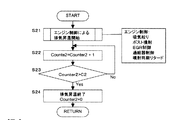
次に、前述した触媒活性化のための排気昇温手段について説明する。その手法は各種知られているが、ここでは代表的な2つの例を示す。図3は第1の手法であり、まずS21にてエンジン制御により排気温度を上昇させる。排気温度を上昇させるエンジン制御としては、吸気絞り弁8の開度を減じる制御、燃料噴射系により燃焼行程後半から排気行程までの間にポスト噴射を行わせる制御、燃料噴射時期を遅らせる噴射時期リタード制御、EGR弁10の開度を減じる制御、過給器4のノズル開度を減じる制御などであり、通常はこれらのうちいくつかを組み合わせて実行する。
Next, the exhaust gas temperature raising means for catalyst activation described above will be described. Various methods are known, but here, two typical examples are shown. FIG. 3 shows the first method. First, in S21, the exhaust temperature is raised by engine control. As engine control for raising the exhaust temperature, control for reducing the opening of the
次いでS22〜S23の処理により、排気昇温を開始してから設定時間C2が経過するまでをカウンタCouter2により計時する。Counter2>C2となったらS24にて前記排気昇温制御を終了させると共にCounter2を0にリセットし、図2のルーチンに戻る。前記設定時間C2を、図2の処理にて検出した排気温度T_oxyに応じて、T_oxyが低温であるほどC2が長くなるように可変設定する手法もある。 Next, by the processing of S22 to S23, the counter Couuter2 measures the time from when the exhaust gas temperature raising is started until the set time C2 elapses. When Counter2> C2, the exhaust gas temperature raising control is terminated at S24, Counter2 is reset to 0, and the routine returns to the routine of FIG. There is also a method in which the set time C2 is variably set so that C2 becomes longer as T_oxy is lower in temperature, in accordance with the exhaust temperature T_oxy detected in the process of FIG.
図4は触媒活性化のための第2の手法である。当初のS31での排気昇温制御については図3と同様である。この処理では、昇温終了条件として、S32〜S33にて酸化触媒11の出口排気温度T_oxyを検出している点で図3と異なる。すなわち、T_oxyがT2に達するまでは排気昇温を継続し、T_oxyがT2を超えたときに排気昇温を終了させる(S34)。
FIG. 4 shows a second method for activating the catalyst. The initial exhaust gas temperature raising control in S31 is the same as that in FIG. This process differs from FIG. 3 in that the outlet exhaust temperature T_oxy of the
1 エンジン本体
2 コモンレール
3 燃料噴射弁
4 ターボ過給器
5 吸気通路
6 排気通路
7 エアフローメータ
8 吸気絞り弁
9 EGR通路
10 EGR弁
11 酸化触媒
12 NOxトラップ触媒
13 DPF(排気微粒子フィルタ)
14 回転速度センサ
15 アクセル開度センサ
16 水温センサ
17 レール圧センサ
20 コントロールユニット
21,22,23 温度センサ
DESCRIPTION OF
DESCRIPTION OF SYMBOLS 14
Claims (6)
前記酸化触媒出口側の排気温度を検出する温度センサと、
前記温度センサからの信号に基づき酸化触媒の活性状態を判定する触媒活性判定手段と、
前記触媒活性判定手段の判定結果に基づき、酸化触媒の不活性時に排気温度を上昇させる排気昇温手段と、
前記排気昇温手段による前記酸化触媒の活性に必要な期間の排気昇温を実行したのち、その実行終了後から所定時間が経過するまでは前記触媒活性判定の結果にかかわらず排気昇温手段による昇温を抑制する昇温抑制手段と、
を有することを特徴とするエンジンの排気浄化装置。 An oxidation catalyst interposed in the exhaust passage of the diesel engine;
A temperature sensor for detecting the exhaust temperature on the oxidation catalyst outlet side;
Catalyst activity determination means for determining an activation state of the oxidation catalyst based on a signal from the temperature sensor;
Based on the determination result of the catalyst activity determining means, exhaust temperature raising means for raising the exhaust temperature when the oxidation catalyst is inactive,
Wherein after executing the exhaust gas Atsushi Nobori activity in the period necessary for the oxidation catalyst that by the exhaust Atsushi Nobori means, that after execution end until a predetermined time elapses the catalyst activity irrespective of the result of the determination exhaust Atsushi Nobori Temperature rise suppression means for suppressing temperature rise by means;
An exhaust emission control device for an engine characterized by comprising:
Priority Applications (1)
| Application Number | Priority Date | Filing Date | Title |
|---|---|---|---|
| JP2003282967A JP4345397B2 (en) | 2003-07-30 | 2003-07-30 | Engine exhaust purification system |
Applications Claiming Priority (1)
| Application Number | Priority Date | Filing Date | Title |
|---|---|---|---|
| JP2003282967A JP4345397B2 (en) | 2003-07-30 | 2003-07-30 | Engine exhaust purification system |
Publications (2)
| Publication Number | Publication Date |
|---|---|
| JP2005048701A JP2005048701A (en) | 2005-02-24 |
| JP4345397B2 true JP4345397B2 (en) | 2009-10-14 |
Family
ID=34268011
Family Applications (1)
| Application Number | Title | Priority Date | Filing Date |
|---|---|---|---|
| JP2003282967A Expired - Fee Related JP4345397B2 (en) | 2003-07-30 | 2003-07-30 | Engine exhaust purification system |
Country Status (1)
| Country | Link |
|---|---|
| JP (1) | JP4345397B2 (en) |
Families Citing this family (5)
| Publication number | Priority date | Publication date | Assignee | Title |
|---|---|---|---|---|
| JP4544036B2 (en) * | 2005-05-31 | 2010-09-15 | 日産自動車株式会社 | In-cylinder direct injection spark ignition internal combustion engine controller |
| EP1728996A1 (en) | 2005-05-31 | 2006-12-06 | Nissan Motor Co., Ltd. | Combustion control method and apparatus for a direct injection spark ignition internal combustion engine |
| JP4232823B2 (en) | 2006-12-26 | 2009-03-04 | トヨタ自動車株式会社 | Exhaust gas purification device for internal combustion engine |
| JP4893493B2 (en) * | 2007-06-19 | 2012-03-07 | トヨタ自動車株式会社 | Exhaust gas purification device for internal combustion engine |
| JP5999038B2 (en) * | 2013-07-08 | 2016-09-28 | トヨタ自動車株式会社 | EGR valve control device for internal combustion engine |
-
2003
- 2003-07-30 JP JP2003282967A patent/JP4345397B2/en not_active Expired - Fee Related
Also Published As
| Publication number | Publication date |
|---|---|
| JP2005048701A (en) | 2005-02-24 |
Similar Documents
| Publication | Publication Date | Title |
|---|---|---|
| JP4055670B2 (en) | Engine exhaust purification system | |
| US9051859B2 (en) | Exhaust gas purification device and control method for exhaust gas purification device | |
| JP5382219B2 (en) | Diesel engine exhaust purification system | |
| JP2010151058A (en) | Exhaust emission control device for diesel engine | |
| US9512785B2 (en) | Exhaust gas purification system for internal combustion engine | |
| EP3133258B1 (en) | Control system for internal combustion engine and control method | |
| JP4371045B2 (en) | Exhaust gas purification device for internal combustion engine | |
| JP4857957B2 (en) | Engine control device | |
| JP4140397B2 (en) | Activity determination device for engine oxidation catalyst | |
| KR100683267B1 (en) | Exhaust purifying apparatus and exhaust purifying method for internal combustion engine | |
| JP4267414B2 (en) | Catalyst control device for internal combustion engine | |
| JP4114077B2 (en) | Exhaust gas purification device for internal combustion engine | |
| JP6589365B2 (en) | Exhaust gas purification system | |
| JP5009189B2 (en) | Exhaust gas purification device for internal combustion engine | |
| JP4613787B2 (en) | Exhaust gas purification device for internal combustion engine | |
| JP4345397B2 (en) | Engine exhaust purification system | |
| JP4435300B2 (en) | Control device for internal combustion engine | |
| JP5310166B2 (en) | Engine exhaust purification system | |
| JP2005048673A (en) | Exhaust emission control device for engine | |
| JP2010196569A (en) | Exhaust emission control system and exhaust emission control method | |
| JP4500765B2 (en) | Exhaust gas purification device for internal combustion engine | |
| JP2009002192A (en) | Exhaust emission control device for internal combustion engine | |
| JP2012026289A (en) | Exhaust emission control device for internal combustion engine | |
| EP4357600A1 (en) | Control device for catalyst temperature raising system | |
| JP4539466B2 (en) | Exhaust gas purification system for internal combustion engine |
Legal Events
| Date | Code | Title | Description |
|---|---|---|---|
| A621 | Written request for application examination |
Free format text: JAPANESE INTERMEDIATE CODE: A621 Effective date: 20060529 |
|
| A977 | Report on retrieval |
Free format text: JAPANESE INTERMEDIATE CODE: A971007 Effective date: 20090219 |
|
| A131 | Notification of reasons for refusal |
Free format text: JAPANESE INTERMEDIATE CODE: A131 Effective date: 20090303 |
|
| A521 | Request for written amendment filed |
Free format text: JAPANESE INTERMEDIATE CODE: A523 Effective date: 20090422 |
|
| TRDD | Decision of grant or rejection written | ||
| A01 | Written decision to grant a patent or to grant a registration (utility model) |
Free format text: JAPANESE INTERMEDIATE CODE: A01 Effective date: 20090623 |
|
| A01 | Written decision to grant a patent or to grant a registration (utility model) |
Free format text: JAPANESE INTERMEDIATE CODE: A01 |
|
| A61 | First payment of annual fees (during grant procedure) |
Free format text: JAPANESE INTERMEDIATE CODE: A61 Effective date: 20090706 |
|
| R150 | Certificate of patent or registration of utility model |
Ref document number: 4345397 Country of ref document: JP Free format text: JAPANESE INTERMEDIATE CODE: R150 Free format text: JAPANESE INTERMEDIATE CODE: R150 |
|
| FPAY | Renewal fee payment (event date is renewal date of database) |
Free format text: PAYMENT UNTIL: 20120724 Year of fee payment: 3 |
|
| FPAY | Renewal fee payment (event date is renewal date of database) |
Free format text: PAYMENT UNTIL: 20120724 Year of fee payment: 3 |
|
| FPAY | Renewal fee payment (event date is renewal date of database) |
Free format text: PAYMENT UNTIL: 20130724 Year of fee payment: 4 |
|
| FPAY | Renewal fee payment (event date is renewal date of database) |
Free format text: PAYMENT UNTIL: 20140724 Year of fee payment: 5 |
|
| LAPS | Cancellation because of no payment of annual fees |