JP4342015B2 - Label feeder - Google Patents
Label feeder Download PDFInfo
- Publication number
- JP4342015B2 JP4342015B2 JP35568698A JP35568698A JP4342015B2 JP 4342015 B2 JP4342015 B2 JP 4342015B2 JP 35568698 A JP35568698 A JP 35568698A JP 35568698 A JP35568698 A JP 35568698A JP 4342015 B2 JP4342015 B2 JP 4342015B2
- Authority
- JP
- Japan
- Prior art keywords
- label
- tape
- roll
- folder
- label roll
- Prior art date
- Legal status (The legal status is an assumption and is not a legal conclusion. Google has not performed a legal analysis and makes no representation as to the accuracy of the status listed.)
- Expired - Fee Related
Links
Images


Description
【0001】
【発明の属する技術分野】
本発明は、缶、瓶、ペットボトル、箱等の物品に対してラベルを貼り付けるラベラーに関し、特にラベル貼り部に対してラベルテープを供給するための装置に関する。
【0002】
【従来の技術】
従来のラベラーは、図9に示すように、ラベルを貼るべき物品の走行ライン1に沿って2台のラベリングマシン2、3を配置している。ラベリングマシン2、3はそれぞれ、ラベルを剥離テープに貼り付けた構成のラベルテープ5を繰り出すラベルロール6を保持して回転可能なラベルフォルダ7と、ラベルテープ5の張力を制御するテンションコントロール部8と、ラベルテープ5を屈曲させることによりラベルを剥離テープから剥がして物品に貼り付けるラベル貼り部9と、ラベルを剥がした後の剥離テープを巻き取る巻取部10等を備えている。そして2台のラベリングマシン2、3は、一方がメイン、他方が予備として使用されている。すなわち、各ラベリングマシン2、3のラベルフォルダ7にはそれぞれ、1巻のラベルロールしかセットできないため、通常はメインのラベリングマシン2でのラベル貼り動作を行い、そのラベリングマシン2のラベルロール6がなくなる直前に、メインから予備のラベリングマシン3に切り換え、予備を使用している間に、メインのラベリングマシン2に作業者が手作業でラベルロール補給を行い、その補給作業が終わると、予備から再びメインに切り換えるという作業を行っている。この補給作業は、貼るラベルによっても異なるが、小さいラベルを缶ジュース等に貼る場合には、30分に1回程度必要であった。
【0003】
【発明が解決しようとする課題】
最近、生産ラインの省人化、高能力化が進んでいる中で、更に高速化が進もうとしている。このような中で30分に1回或いはそれ以上の頻度でのラベルロール補給は、ほとんどラベラーに作業者がつきっきりの状態になってしまい、省人化に反した状況になってしまう。
【0004】
本発明はかかる問題点に鑑みてなされたもので、ラベルロール補給頻度を大幅に削減し、作業者の作業負担を軽減して省人化を可能とするラベルロール供給装置を提供することを目的とする。
【0005】
【課題を解決するための手段】
本発明は、ラベル貼り部に対してラベルテープを繰り出すラベルロールを保持したラベルフォルダの上方、側方等に、そのラベルフォルダから残量の少なくなったラベルロールを取り外して排出する残ラベルロール排出装置と、複数のラベルロールを保管するラベルロール保管装置と、該ラベルロール保管装置の一つのラベルロールを前記ラベルフォルダにセットする新ラベルロールセット装置を配置し、更に、前記ラベルフォルダからラベル貼り部に到るラベルテープの走行経路に、ラベルフォルダに保持されているラベルロールからラベル貼り部につながっているラベルテープを切断し、ラベル貼り部側のラベルテープ端部に、ラベルフォルダに新たにセットしたラベルロールのラベルテープ先端を接続するラベルテープ継ぎ装置を設けるという構成としたものである。
【0006】
本発明はこの構成により、ラベルロール保管装置に複数のラベルロールをセットしておくと、ラベルフォルダ上のラベルロールが残り少なくなってラベルロール補給が必要となった時、ラベルテープの走行を停止し、ラベルテープ継ぎ装置がラベルロールからラベル貼り部につながっているラベルテープを切断し、残ラベルロール排出装置がラベルフォルダからラベルロールを取り外して排出し、新ラベルロールセット装置がラベルロール保管装置の一つのラベルロールをラベルフォルダにセットし、ラベルテープ継ぎ装置が、そのラベルロールのラベルテープ先端を、ラベル貼り部につながっているラベルテープ端部に接続するという動作を行ってラベルロール補給を自動的に行うことができ、この動作をラベルロール保管装置に予めセットした複数のラベルロールについて繰り返すことで、長時間の無人運転が可能となり、省人化を図ることができる。
【0007】
【発明の実施の形態】
本発明のラベル供給装置は、ラベル貼り部に対してラベルテープを繰り出すラベルロールを保持して回転可能なラベルフォルダと、該ラベルフォルダから残量の少なくなったラベルロールを取り外して排出する残ラベルロール排出装置と、複数のラベルロールを保管するラベルロール保管装置と、該ラベルロール保管装置の一つのラベルロールを前記ラベルフォルダにセットする新ラベルロールセット装置と、前記ラベルフォルダからラベル貼り部に到るラベルテープの走行経路に配置され、ラベルフォルダに保持されているラベルロールからラベル貼り部につながっているラベルテープを切断し、ラベル貼り部側のラベルテープ端部に、前記ラベルフォルダに新たにセットしたラベルロールのラベルテープ先端を接続するラベルテープ継ぎ装置とを有するものである。
【0008】
ここで、前記ラベルフォルダを、ラベルロールを上方から着脱可能で且つラベルロールを水平に保持して回転可能な支持軸を備えた構成とし、前記ラベルロール保管装置を、前記ラベルフォルダの支持軸と同一軸線上で且つラベルフォルダの上方に複数のラベルロールを多段に保持すると共に、下降することで保管しているラベルロールを前記ラベルフォルダの支持軸に保持させうる構成とし、更に、前記新ラベルロールセット装置を前記ラベルロール保管装置を昇降させる構成とする。この構成としたことで、ラベルフォルダの上方にラベルロール保管装置を配置することが可能となり、装置の設置スペースを小さくでき、しかも、ラベルロール保管装置を下降させるのみで、ラベルロールをラベルフォルダにセットできるので、新ラベルロールセット装置の構造がきわめて簡単となる。
【0009】
また、前記ラベルフォルダの支持軸を、水平に置かれたラベルロールの下面を外径部分まで支持する支持板を備えると共にその支持板の外周に、中心をはさんで両側に延びる溝を備えた構成とし、前記ラベルロール保管装置を、水平に置かれたラベルロールの下面を、中心をはさんだ両側で保持する一対の支持板を多段に備え、且つ、その支持板が、前記ラベルフォルダの支持板に形成している溝を上下に通過しうる突出部を備えた構成とする。この構成としたことで、ラベルロールが軸線方向にずれて崩れやすい場合にも、ラベルフォルダの支持板及びラベルロールの支持板でそれぞれラベルロールを安定して支持することができ、且つラベルロール保管装置を下降させることでラベルロール保管装置からラベルフォルダにラベルロールを支障なく受け渡すことができる。
【0010】
前記したラベル供給装置において、前記ラベルロール保管装置の支持板に、その支持板に保持させたラベルロールから引き出されたラベルテープの先端を、ラベルテープ接続に適した位置に保持するガイドを設けておくことが好ましい。この構成とすると、ラベルロール保管装置を下降させてラベルロールをラベルフォルダにセットした時、同時にそのラベルロールのラベルテープ先端をラベルテープ継ぎ装置でのラベルテープ継ぎ動作に適した位置に供給でき、敏速にラベルテープ継ぎ動作に入ることができる。
【0011】
前記ラベルテープ継ぎ装置としては、ラベルフォルダに保持されているラベルロールからラベル貼り部に到るラベルテープの走行経路に配置され、ラベルテープを一時的にクランプするテープクランプ装置と、そのテープクランプ装置よりもラベルフォルダ側でラベルテープを切断するラベルカッタと、該ラベルカッタよりもラベルフォルダ側に配置され、ラベルフォルダに新たにセットしたラベルロールのラベルテープをニップしてその先端を、前記テープクランプ装置で把持されているラベルテープの端部にほぼ突き合わせる位置に送り出すラベル位置合わせ装置と、突き合わせた状態のラベルテープの両端部に粘着テープを貼り付けるテープ貼付装置とを有する構成とすることができ、これにより、ラベル貼り部につながっているラベルテープの端部に、新たにラベルフォルダにセットしたラベルロールのラベルテープ先端を接続することができる。
【0012】
【実施例】
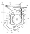
以下、図面に示す本発明の好適な実施例を説明する。図1は本発明の一実施例によるラベル供給装置を備えたラベラーを示す概略平面図、図2はそのラベル供給装置の概略平面図、図3はそのラベル供給装置の概略側面図であり、図9に示す従来例と同一部品には同一符号を付している。1は、ラベルを貼るべき物品、例えば缶ジュース等を搬送する走行ラインであり、その走行ライン1に沿ってメインのラベリングマシン12と予備のラベリングマシン3が配置されている。予備のラベリングマシン3は従来と同一のものであり、ラベルロール6を保持するラベルフォルダ7と、ラベルテープ5の張力を制御するテンションコントロール部8と、ラベルを物品に貼り付けるラベル貼り部9と、ラベルを剥がした後の剥離テープを巻き取る巻取部10等を備えている。
【0013】
メインのラベリングマシン12は、走行ライン1を走行する物品に対してラベルを貼り付けるラベル貼り部9と、そのラベル貼り部9にラベルテープ5を供給するラベル供給装置14と、ラベルを剥がした後の剥離テープ5aを適当な長さに切断して回収するブロワーカッター15を備えている。ラベル貼り部9の構造は従来と同様であり、既設のラベリングマシン(図9に示すラベリングマシン2)のラベル貼り部9をそのまま使用することもできる。換言すれば、図9に示すラベラーのメイン側のラベリングマシン2の近傍に、ラベル供給装置14とブロワーカッター15を配置することで簡単にラベリングマシン12を構成できる。なお、ブロワーカッター15に代えて、大量の剥離テープ5aを巻き取ることの可能な巻取部を設けても良い。
【0014】
ラベル供給装置14は、ラベル貼り部9に対してラベルテープ5を繰り出すラベルロール6を保持して回転可能なラベルフォルダ21を備えている。本実施例におけるラベルフォルダ21は、ラベルロール6を水平に、即ちラベルロール6の軸線が垂直となるように保持する構成のものであり、図4(a)、(b)に拡大して示すように、垂直に配置された支持軸23と、その支持軸23を回転自在に保持した支持体24を有している。支持軸23の上端には、ラベルロール6の巻芯に嵌合する挿入部25とラベルロール6の下面を支持する支持板26が取り付けられており、ラベルロール6を上から出し入れ可能な構成となっている。更に、支持板26は、ラベルロール6の外径部分まで保持可能な大きさを有しており、崩れやすいラベルロール6でも安定して支持可能である。またその支持板26には、中心をはさんだ両側に複数の溝28が形成されている。支持軸23には、ギア27が取り付けられており、そのギア27を介してモータ(図示せず)で回転駆動される構成となっている。この構成により、ラベルロール6を支持軸23で保持した状態で、支持軸23を送り出しモータによってラベルテープ送り出し方向に回転させ、引き出されるラベルテープ5の張力を小さくすることができる。また、このモータには、支持軸23を所定の回転方向位置(支持板26の溝28が、図1、図2に示すように左右を向く位置)に停止させる制御装置が接続されている。
【0015】
図1〜図3において、ラベルフォルダ21の近傍には、ラベルフォルダ21から、残量の少なくなったラベルロール(以下残ラベルロールという)を取り外して排出する残ラベルロール排出装置31が設けられている。この残ラベルロール排出装置31は、支点Oを中心として水平面内で旋回可能な旋回アーム32と、その先端に取り付けられ残ラベルロールをつかむチャック装置33と、旋回アーム32を旋回させるロータリアクチュエータ等の旋回手段34と、旋回アーム32を昇降させるエアシリンダ等の昇降手段35等を備えており、旋回アーム32が上昇した位置で図2に示す位置から反時計方向に旋回してチャック装置33がラベルフォルダ21の支持軸23の上方に移動し、次いで、チャック装置33が開いた状態で旋回アーム32が下降してチャック装置33が残ラベルロールを挟みうる位置に下降し、次いでチャック装置33が残ラベルロールをつかみ、その後、旋回アーム32が上昇し、次いで元の位置に旋回し、その後チャック装置33が残ラベルロールを解放することで、ラベルフォルダ21上の残ラベルロールを自動的に排出できる構成となっている。
【0016】
ラベルフォルダ21の上方には、複数のラベルロール6を保管するラベルロール保管装置41が設けられている。このラベルロール保管装置41は、複数のラベルロール6を水平状態で且つ中心がラベルフォルダ21の中心軸線上に位置するように多段に保持する構成のものであり、枠体42と、その枠体42の向かい合った側面に対になって且つ多段に取り付けられた支持板44、44を備え、各対の支持板44、44上にラベルロール6を乗せるようになっている。各対の支持板44、44は、図5に示すように、向かい合った端部に、ラベルロール6を保持するための複数の突出部44aを備えている。この突出部44aは、ラベルフォルダ21の支持板26に形成している溝28に対応して形成しており、図2に示すように、支持板26の溝28の位置を突出部44aに合わせると、突出部44aが溝28を上下に通り抜け可能となる。従って、新たなラベルロール6を保持した支持板44、44を下降させ、ラベルフォルダ21の支持板26を通り抜けさせることにより、そのラベルロール6をラベルフォルダ21の支持板26上にセットすることができる。多段に配置した支持板44の上下方向の間隔は、下側の支持板44を下降させて保持していたラベルロール6をラベルフォルダ21の支持板26上に乗せ、更に支持板26の回転に干渉しない位置まで下降させた状態とした時に、上側の支持板44が支持板26及びその上のラベルロール6の回転に干渉することがなく、且つ残ラベルロール排出装置31の動作にも干渉しないように定めている。
【0017】
図5において、一対の支持板44、44の上面には、その上に乗せるラベルロール6の位置を規制するためのガイド46が設けられており、且つ一方の支持板44の端部にはラベルロール6から引き出したラベルテープ5Aの先端を後述するラベルテープ継ぎ動作に適した所定位置に保持するためのガイド47が設けられている。
【0018】
図1〜図3において、ラベルロール保管装置41の枠体42は、垂直に設けられているガイド棒49に移動可能に保持され且つエアシリンダ等の駆動装置(図示せず)によって昇降可能な構成となっている。かくして、この枠体42を下降させることで、支持板44上に乗せているラベルロール6を、ラベルフォルダ21に供給することができる。従って、枠体42を昇降させるための機構は、ラベルロール保管装置41に保管している一つのラベルロールをラベルフォルダ21にセットする新ラベルロールセット装置を構成する。
【0019】
図1、図2において、ラベルフォルダ21からラベル貼り部9に到るラベルテープ5の走行経路には、ラベルフォルダ21に保持されているラベルロール(残ラベルロール)からラベル貼り部9につながっているラベルテープ5を切断し、ラベル貼り部側のラベルテープ端部に、ラベルフォルダ21に新たにセットしたラベルロールのラベルテープ先端を接続するラベルテープ継ぎ装置51と、ラベルテープ5の張力を制御するテンションコントロール部52が設けられている。
【0020】
図6、図7、図8は、このラベルテープ継ぎ装置51を拡大して且つそれぞれ異なる作動状態で示す概略平面図である。図6〜図8において、53はラベルテープ5をクランプするためのテープクランプ装置であり、定位置に設けられた受けローラ53aと、ラベルテープ5を受けローラ53aに押し付けるための押えローラ53bと、それを往復動させるエアシリンダ等の駆動装置53c等を有している。54は、ラベルテープ5を、テープクランプ装置53よりもラベルフォルダ21側の位置で切断するためのラベルカッタであり、ラベルテープ5の走行経路の下方から上昇してラベルテープ5を切断しうるように配置されている。
【0021】
55は、ラベルカッタ54よりもラベルフォルダ21側に配置され、ラベルフォルダ21に新たにセットしたラベルロールのラベルテープ5Aの先端位置を所定位置にセットするためのラベル位置合わせ装置であり、定位置に設けられた受けローラ55aと、その受けローラ55aを回転駆動するモータ(図示せず)と、ラベルテープ5Aを受けローラ55aに押し付けるための押えローラ55bと、それを往復動させるエアシリンダ等の駆動装置55cを有している。受けローラ55a及び押えローラ55bは、図7に示すように、新たなラベルロール6を保持している支持板44に設けられているガイド47、47で規制されているラベルテープ5Aの先端を受け入れることができる位置に配置されている。56は、ラベルテープ5Aの先端位置を検出する光センサ等のラベル先端検出器である。
【0022】
図6〜図8において、61はラベルテープの端部同志を接続するための粘着テープ、62はその粘着テープ61を供給するテープホルダ、63は粘着テープ61を外周面に一時的に貼り付けて搬送するテープフィードローラ、64はテープフィードローラ63の外周面上の粘着テープ61を一定長さに切断するテープカッタ、65は、テープフィードローラ63から一定長さの粘着テープを受け取り、ラベルテープ5、5Aの端部に貼り付けるテープ貼付装置である。このテープ貼付装置65は、粘着テープ61を吸着保持する吸着ヘッド65aと、その吸着ヘッド65aを出し入れするエアシリンダ等の駆動装置65bと、吸着ヘッド65aをテープフィードローラ63に対向する位置(図6に示す位置)とラベルテープ5に対向する位置(図7、図8に示す位置)に旋回させる旋回装置65c等を備えている。66は、ラベルテープ5、5Aの端部に粘着テープを貼り付ける際にそのラベルテープ5、5Aの背面を受けるニップ受け装置であり、ニップ受け66aとそれを往復動させるエアシリンダ等の駆動装置66bを備えている。
【0023】
図1、図2において、70は操作盤であり、以下に説明する動作をシーケンス制御する装置が内蔵されている。
【0024】
次に、上記構成のラベラーによるラベル貼り動作を説明する。今、図1〜図3に示すように、ラベルロール保管装置41には新たなラベルロール6がセットされており、最下段のラベルロール6がラベルフォルダ21にセットされているものとする。この際、ラベルロール保管装置41の各支持板44上にセットされたラベルロール6は、図5に示すように、ガイド46で所定位置に位置決めされ、且つラベルテープ5Aがガイド47、47間を通って少し突出した状態にセットされている。図1〜図3において、通常はメインのラベリングマシン12が作動し、走行ライン1を走行中の物品に対してラベル貼り動作が行われる。すなわち、ラベルフォルダ21に保持されたラベルロール6からラベルテープ5が引き出され、ラベル貼り部9によって走行ライン1の物品に次々とラベルが貼られてゆき、ラベルを剥がした後の剥離テープ5aはブロワーカッター15によって適当な長さに切断して屑箱に回収されている。
【0025】
ラベルフォルダ21にセットされているラベルロール6の残量が少なくなると、それを残量検出手段(図示せず)が検出し、予備のラベリングマシン3に切り換えてラベル貼り動作を継続する。そして、ラベリングマシン3の運転中に、メインのラベリングマシン12におけるラベルロール切り換え動作が以下の手順で自動的に行われる。まず、図6において、ラベルテープ5の走行が停止した時点で、テープクランプ装置53が作動してラベルテープ5をクランプする。次いで、ラベルカッター54が上昇してきて、ラベルフォルダ21上の残ラベルロール6につながっているラベルテープ5を切断する。その後、図1〜図3に示す残ラベルロール排出装置31が作動して、ラベルフォルダ21上の残ラベルロール6を取り出し、排出する。
【0026】
次に、ラベルロール保管装置41が一段下降して、支持板44上に保持していた新たなラベルロール6をラベルフォルダ21に保持させる。この時、新たなラベルロール6のラベルテープ5Aの先端は、図5、図7に示すように、ガイド47、47で位置を規制され且つガイド47、47より少し突出しているので、自動的にラベル位置合わせ装置55のローラ55a、55b間に挿入される。次に、押えローラ55bがそのラベルテープ5Aを受けローラ55aとの間にニップし、次いで、受けローラ55aが回転してラベルテープ5Aを送り出す。そして、ラベルテープ5A先端をラベル先端検出器56で検出した後、更に所定量だけ送り出して受けローラ55aは停止する。これにより、図8に示すように、テープクランプ装置53でクランプされているラベルテープ5(ラベル貼り部9側のラベルテープ5)の端部と、ラベルフォルダ21に新たにセットしたラベルロール6のラベルテープ5Aの端部をほぼ突き合わせた状態とすることができる。
【0027】
以上の動作と並行して、図6に示すように、テープホルダ62から粘着テープ61が引き出され、テープフィードローラ63の外周面に一時的に貼り付けられ且つテープカッタ64によって一定長さに切断され、受け渡し位置Pに次々と送られてくる。そして、テープ貼付装置65の吸着ヘッド65aがその粘着テープ61を受け取り、次いで、図8に示すように貼付位置に旋回する。その後、ニップ受け66aが前進して、ラベルテープ5、5Aの端部を支持した状態で、吸着ヘッド65aが前進し、保持していた粘着テープ61をラベルテープ5、5Aの突き合わせた端部に貼り付ける。以上により、新旧のラベルテープ5、5Aが接続される。その後、吸着ヘッド65a及びニップ受け66aが後退してラベルテープ5、5Aを解放すると共に、その前後のテープクランプ装置53、ラベル位置合わせ装置55の押えローラ53b、55bも共に後退してラベルテープ5、5Aを解放する。
【0028】
以上のラベルロール切り換えが終了すると、メインのラベリングマシン12が作動を開始し、同時に予備のラベリングマシン3が作動を停止する。その後は再びメインのラベリングマシン12によるラベル貼り動作が行われる。そして、ラベルフォルダ21上のラベルロール6の残量が少なくなると上記した手順で再び、切り換え動作が行われる。このようにして、ラベルロール保管装置41に予めセットしている数のラベルロール6がなくなるまで自動運転が行われる。
【0029】
ラベルロール保管装置41の最後の(最上部の)ラベルロール6を使用し、その残量が少なくなった時には、予備のラベリングマシン3に切り換えて、ラベル貼り動作を継続し、その間に、上記したように、残ラベルロール6につながっているラベルテープ5を切断し且つ残ラベルロールを排出する。その後、ラベルロール保管装置41の枠体42を最上方位置に戻し、最下段の支持板44、44上に新たなラベルロール6を手作業でセットした後、直ちに、ラベルロール保管装置41を下降させて、先にセットしたラベルロール6をラベルフォルダ21上に乗せ、その後は上記した手順で新旧のラベルテープの端部同志を接続し、直ちにメインのラベリングマシン12に切り換え、定常運転に入る。その後、メインのラベリングマシン12の運転中の適当な時期に、第二段以上の支持板44上に新たなラベルロール6をセットしてゆく。その後は再び、上記した手順による自動運転が行われる。
【0030】
以上のように、本発明の実施例によるラベル供給装置14を用いると、ラベルロール保管装置41に保管している複数のラベルロールを順次自動的に切り換えて使用することができ、長期間に渡って無人運転することができる。また、ラベルロール保管装置41に保管していたラベルロールを使い切った後は、ラベルロール保管装置41の最下段に1個のラベルロール6をセットし、そのラベルロール6を、ラベルフォルダ上の残ラベルロールと切り換える動作を行う間だけ、メインのラベリングマシン12の運転を停止するのみで、ラベリングマシン12の運転を再開でき、従って予備のラベリングマシン3の運転時間を短くでき、それにセットしているラベルロール6の消費を少なくできる。更に、ラベルロール保管装置41に対する新たなラベルロール6のセットは、単に支持板44上にラベルロール6を乗せ、ラベルテープの先端をガイド47、47の間に通しておくという簡単な操作でよいため、作業が容易で且つ短時間で実施でき、作業者の作業負担を大幅に削減して省人化を図ることができる。
【0032】
【発明の効果】
以上のように、本発明のラベル供給装置は、ラベルロール保管装置に複数のラベルロールをセットしておくと、ラベルフォルダ上のラベルロールが残り少なくなってラベルロール補給が必要となった時、ラベルテープの走行を停止し、ラベルテープ継ぎ装置がラベルロールからラベル貼り部につながっているラベルテープを切断し、残ラベルロール排出装置がラベルフォルダからラベルロールを取り外して排出し、新ラベルロールセット装置がラベルロール保管装置の一つのラベルロールをラベルフォルダにセットし、ラベルテープ継ぎ装置が、そのラベルロールのラベルテープ先端を、ラベル貼り部につながっているラベルテープ端部に接続するという動作を行ってラベルロール補給を自動的に行うことができ、長時間の無人運転が可能となり、省人化を図ることができるという効果が得られる。また、このラベル供給装置は、既設のラベラーに対しても容易に取り付けることができるという効果も有している。
【図面の簡単な説明】
【図1】本発明の一実施例によるラベル供給装置を備えたラベラーを示す概略平面図
【図2】ラベル供給装置の概略平面図
【図3】ラベル供給装置の概略側面図
【図4】(a)はラベルフォルダの主要部の概略側面図
(b)はその概略平面図
【図5】ラベルロール保管装置の概略水平断面図
【図6】ラベルテープ継ぎ装置及びその近傍を示す概略平面図
【図7】ラベルテープ継ぎ装置及びその近傍を、図6とは異なる作動状態で示す概略平面図
【図8】ラベルテープ継ぎ装置及びその近傍を、図6、図7とは異なる作動状態で示す概略平面図
【図9】従来のラベラーを示す概略平面図
【符号の説明】
1 物品の走行ライン
3 ラベリングマシン
5、5A ラベルテープ
6 ラベルロール
9 テープ貼り部
12 ラベリングマシン
14 ラベル供給装置
15 ブロワーカッター
21 ラベルフォルダ
23 支持軸
26 支持板
28 溝
31 残ラベルロール排出装置
41 ラベルロール保管装置
42 枠体
44 支持板
44a 突出部
46、47 ガイド
51 ラベルテープ継ぎ装置
52 テンションコントロール部
53 テープクランプ装置
54 ラベルカッタ
55 ラベル位置合わせ装置
61 粘着テープ
63 テープフィードローラ
65 テープ貼付装置
66 ニップ受け装置[0001]
BACKGROUND OF THE INVENTION
The present invention relates to a labeler for attaching a label to an article such as a can, a bottle, a plastic bottle, or a box, and more particularly, to an apparatus for supplying a label tape to a label attaching portion.
[0002]
[Prior art]
As shown in FIG. 9, the conventional labeler arranges two
[0003]
[Problems to be solved by the invention]
In recent years, as production lines are labor-saving and high-capacity is being advanced, higher speeds are being promoted. Under such circumstances, replenishment of the label roll once every 30 minutes or more often results in a situation where the operator is almost in contact with the labeler and is in a situation contrary to labor saving.
[0004]
The present invention has been made in view of such problems, and an object of the present invention is to provide a label roll supply device that can greatly reduce the frequency of label roll replenishment, reduce the burden on the operator, and save labor. And
[0005]
[Means for Solving the Problems]
The present invention provides a remaining label roll discharge that removes and discharges a label roll with a small remaining amount from the label folder above and to the side of the label folder that holds the label roll that feeds the label tape to the labeling portion. An apparatus, a label roll storage device for storing a plurality of label rolls, and a new label roll setting device for setting one label roll of the label roll storage device in the label folder, and further applying a label from the label folder. Cut the label tape connected to the label application part from the label roll held in the label folder in the travel route of the label tape to the label part. A label tape splicing device is provided to connect the label tape tip of the set label roll. Is that a configuration that.
[0006]
With this configuration, when a plurality of label rolls are set in the label roll storage device, the present invention stops the running of the label tape when the label rolls on the label folder are low and the label roll needs to be replenished. The label tape splicing device cuts the label tape connected from the label roll to the label application part, the remaining label roll discharge device removes the label roll from the label folder and discharges it, and the new label roll set device releases the label roll storage device. One label roll is set in the label folder, and the label tape splicing device connects the label tape end of the label roll to the end of the label tape connected to the label affixing section to automatically supply the label roll. This operation can be performed on the label roll storage device in advance. By repeated for a plurality of labels rolls, allows long-hour operation and will, it is possible to save humanized.
[0007]
DETAILED DESCRIPTION OF THE INVENTION
The label supply device according to the present invention includes a label folder that can be rotated while holding a label roll that feeds a label tape to a label attaching portion, and a remaining label that is removed from the label folder and discharged after the label roll with a small remaining amount is removed. A roll discharge device, a label roll storage device for storing a plurality of label rolls, a new label roll setting device for setting one label roll of the label roll storage device in the label folder, and a label applying unit from the label folder Cut the label tape connected to the label application part from the label roll held in the label folder, and connected to the label application part at the label application end of the label application part. Label tape splicing to connect the label tape tip of the label roll set to Those having a location.
[0008]
here, Above The label folder is configured to include a support shaft that can be attached to and detached from above and that can rotate while holding the label roll horizontally, and the label roll storage device is arranged on the same axis as the support shaft of the label folder. A plurality of label rolls are held in a multi-stage above the label folder, and the label roll stored by being lowered is held on the support shaft of the label folder. The label roll storage device is lifted and lowered. The With this configuration By doing The label roll storage device can be placed above the label folder, the installation space of the device can be reduced, and the label roll can be set in the label folder simply by lowering the label roll storage device. The structure of the roll setting device is very simple.
[0009]
In addition, the support shaft of the label folder is provided with a support plate that supports the lower surface of the horizontally placed label roll to the outer diameter portion, and the outer periphery of the support plate is provided with grooves extending on both sides across the center. The label roll storage device comprises a plurality of stages of support plates that hold the lower surface of the label roll placed horizontally on both sides of the center, and the support plates support the label folder. It is configured to have a protrusion that can pass up and down the groove formed in the plate. The With this configuration By doing Even when the label roll is displaced in the axial direction and easily collapses, the label roll can be stably supported by the support plate of the label folder and the support plate of the label roll, and the label roll storage device is lowered. The label roll can be transferred from the label roll storage device to the label folder without any trouble.
[0010]
In the label supply apparatus described above, It is preferable that a guide for holding the tip of the label tape drawn from the label roll held on the support plate at a position suitable for label tape connection is provided on the support plate of the label roll storage device. With this configuration, when the label roll storage device is lowered and the label roll is set in the label folder, the label tape tip of the label roll can be simultaneously supplied to a position suitable for the label tape splicing operation in the label tape splicing device, The label tape splicing operation can be entered promptly.
[0011]
As the label tape splicing device, a tape clamp device that is disposed on a travel route of the label tape from the label roll held in the label folder to the label attaching portion and temporarily clamps the label tape, and the tape clamp device A label cutter for cutting the label tape on the label folder side, and a label roll of the label roll newly set in the label folder which is arranged on the label folder side from the label cutter and nips the leading end of the label tape. It is possible to have a configuration that includes a label alignment device that feeds the label tape that is gripped by the device to a position that substantially abuts, and a tape affixing device that affixes the adhesive tape to both ends of the abutted label tape. This will allow the label connected to the labeling part The end of the tape, it is possible to connect a new label roll set in the label folder label tape tip.
[0012]
【Example】
Hereinafter, preferred embodiments of the present invention shown in the drawings will be described. 1 is a schematic plan view showing a labeler equipped with a label supply apparatus according to an embodiment of the present invention, FIG. 2 is a schematic plan view of the label supply apparatus, and FIG. 3 is a schematic side view of the label supply apparatus. The same parts as those in the conventional example shown in FIG.
[0013]
The
[0014]
The
[0015]
In FIG. 1 to FIG. 3, in the vicinity of the
[0016]
A label
[0017]
In FIG. 5, a
[0018]
In FIG. 1 to FIG. 3, the
[0019]
In FIG. 1 and FIG. 2, the travel route of the
[0020]
6, 7 and 8 are schematic plan views showing the label
[0021]
[0022]
6 to 8, 61 is an adhesive tape for connecting the ends of the label tape, 62 is a tape holder for supplying the
[0023]
In FIG. 1 and FIG. 2,
[0024]
Next, a labeling operation by the labeler having the above configuration will be described. Now, as shown in FIGS. 1 to 3, it is assumed that a
[0025]
When the remaining amount of the
[0026]
Next, the label
[0027]
In parallel with the above operation, as shown in FIG. 6, the
[0028]
When the above label roll switching is completed, the
[0029]
When the last (uppermost)
[0030]
As described above, when the
[0032]
【The invention's effect】
As described above, the label supply device according to the present invention has a plurality of label rolls set in the label roll storage device. Stops running of the tape, the label tape splicing device cuts the label tape connected from the label roll to the label application part, the remaining label roll discharging device removes the label roll from the label folder and discharges it, and the new label roll setting device Sets one label roll of the label roll storage device in the label folder, and the label tape splicing device connects the label tape end of the label roll to the end of the label tape connected to the label attaching portion. Label roll replenishment can be performed automatically, enabling unattended operation for a long time. Ri, there is an advantage that it is possible to save humanized. Moreover, this label supply apparatus also has an effect that it can be easily attached to an existing labeler.
[Brief description of the drawings]
FIG. 1 is a schematic plan view showing a labeler provided with a label supply device according to an embodiment of the present invention.
FIG. 2 is a schematic plan view of a label supply device.
FIG. 3 is a schematic side view of a label supply apparatus.
FIG. 4A is a schematic side view of the main part of a label folder.
(B) is a schematic plan view thereof.
FIG. 5 is a schematic horizontal sectional view of a label roll storage device.
FIG. 6 is a schematic plan view showing a label tape splicing device and its vicinity.
7 is a schematic plan view showing the label tape splicing device and its vicinity in an operating state different from FIG.
8 is a schematic plan view showing the label tape splicing device and the vicinity thereof in an operating state different from those in FIGS. 6 and 7. FIG.
FIG. 9 is a schematic plan view showing a conventional labeler.
[Explanation of symbols]
1 Travel line of goods
3 Labeling machine
5, 5A Label tape
6 Label roll
9 Tape application part
12 Labeling machine
14 Label feeder
15 Blower cutter
21 Label folder
23 Support shaft
26 Support plate
28 groove
31 Remaining label roll discharge device
41 Label roll storage device
42 Frame
44 Support plate
44a protrusion
46, 47 guide
51 Label tape splicing device
52 Tension control section
53 Tape clamp device
54 Label cutter
55 Label alignment device
61 Adhesive tape
63 Tape feed roller
65 Tape applicator
66 Nip receiving device
Claims (3)
Priority Applications (1)
| Application Number | Priority Date | Filing Date | Title |
|---|---|---|---|
| JP35568698A JP4342015B2 (en) | 1998-12-15 | 1998-12-15 | Label feeder |
Applications Claiming Priority (1)
| Application Number | Priority Date | Filing Date | Title |
|---|---|---|---|
| JP35568698A JP4342015B2 (en) | 1998-12-15 | 1998-12-15 | Label feeder |
Publications (2)
| Publication Number | Publication Date |
|---|---|
| JP2000177721A JP2000177721A (en) | 2000-06-27 |
| JP4342015B2 true JP4342015B2 (en) | 2009-10-14 |
Family
ID=18445254
Family Applications (1)
| Application Number | Title | Priority Date | Filing Date |
|---|---|---|---|
| JP35568698A Expired - Fee Related JP4342015B2 (en) | 1998-12-15 | 1998-12-15 | Label feeder |
Country Status (1)
| Country | Link |
|---|---|
| JP (1) | JP4342015B2 (en) |
Families Citing this family (3)
| Publication number | Priority date | Publication date | Assignee | Title |
|---|---|---|---|---|
| JP4841743B2 (en) * | 2000-06-21 | 2011-12-21 | 大阪シーリング印刷株式会社 | Label continuum splicer |
| DE102005006729A1 (en) * | 2005-02-03 | 2006-08-10 | Herma Gmbh | Arrangement for splicing old and new strips of labels comprises an adhesive patch supported by a holder whose position is automatically controlled by the position of the old strip |
| CN115123641A (en) * | 2022-07-28 | 2022-09-30 | 广州市理鑫机械科技有限公司 | Drawer type multi-station automatic laminating and label changing machine |
-
1998
- 1998-12-15 JP JP35568698A patent/JP4342015B2/en not_active Expired - Fee Related
Also Published As
| Publication number | Publication date |
|---|---|
| JP2000177721A (en) | 2000-06-27 |
Similar Documents
| Publication | Publication Date | Title |
|---|---|---|
| JP4895766B2 (en) | Semiconductor wafer protective tape cutting method and protective tape cutting device | |
| JPH01127548A (en) | Method and device for end treatment of paper roll | |
| JPS6356143B2 (en) | ||
| JP4590399B2 (en) | Web-like material reel unwinding device and associated method having a temporary accumulator member for the material unwound in the reel change stage | |
| JPH07144800A (en) | Method and device for connecting material web, especially packing material web | |
| JP4478344B2 (en) | A device that starts operation at the work site of a textile machine that produces cheese | |
| JP4342015B2 (en) | Label feeder | |
| JP4727996B2 (en) | Labeling device | |
| JP2000185852A (en) | Jointing device for unwinding machine | |
| JP3666325B2 (en) | Method and apparatus for supplying wound sheet for wire harness | |
| KR100225722B1 (en) | Apparatus of attaching label of wall paper automatically | |
| US5381983A (en) | Apparatus for drawing out a web end from a web roll | |
| JP2002332146A (en) | Connector for band shaped body | |
| JP4096770B2 (en) | Sheet split winding device | |
| JPH0295643A (en) | Web take-up device | |
| JP2649901B2 (en) | Automatic roll supply system | |
| JP2000344401A (en) | Device for feeding continuous material to printing machine | |
| JP2775439B2 (en) | Web feeder | |
| JPH10157892A (en) | Web carrying device of reel outfitting device | |
| JP4112896B2 (en) | Rubber strip sticking and molding equipment | |
| JPH0948541A (en) | Winding core automatic replenisher in slitter device | |
| JP2001072286A (en) | Automatic rewinding device in slitter device | |
| JP2647536B2 (en) | Adhesive tape application device | |
| JPH0295648A (en) | Web take-up device | |
| JPH10139227A (en) | Head end drawing device of belt material |
Legal Events
| Date | Code | Title | Description |
|---|---|---|---|
| A621 | Written request for application examination |
Free format text: JAPANESE INTERMEDIATE CODE: A621 Effective date: 20051205 |
|
| A977 | Report on retrieval |
Free format text: JAPANESE INTERMEDIATE CODE: A971007 Effective date: 20090417 |
|
| A131 | Notification of reasons for refusal |
Free format text: JAPANESE INTERMEDIATE CODE: A131 Effective date: 20090421 |
|
| A521 | Written amendment |
Free format text: JAPANESE INTERMEDIATE CODE: A523 Effective date: 20090615 |
|
| TRDD | Decision of grant or rejection written | ||
| A01 | Written decision to grant a patent or to grant a registration (utility model) |
Free format text: JAPANESE INTERMEDIATE CODE: A01 Effective date: 20090707 |
|
| A01 | Written decision to grant a patent or to grant a registration (utility model) |
Free format text: JAPANESE INTERMEDIATE CODE: A01 |
|
| A61 | First payment of annual fees (during grant procedure) |
Free format text: JAPANESE INTERMEDIATE CODE: A61 Effective date: 20090707 |
|
| FPAY | Renewal fee payment (event date is renewal date of database) |
Free format text: PAYMENT UNTIL: 20120717 Year of fee payment: 3 |
|
| R150 | Certificate of patent or registration of utility model |
Free format text: JAPANESE INTERMEDIATE CODE: R150 |
|
| FPAY | Renewal fee payment (event date is renewal date of database) |
Free format text: PAYMENT UNTIL: 20120717 Year of fee payment: 3 |
|
| FPAY | Renewal fee payment (event date is renewal date of database) |
Free format text: PAYMENT UNTIL: 20130717 Year of fee payment: 4 |
|
| LAPS | Cancellation because of no payment of annual fees |