JP4339045B2 - Electroless plating apparatus and electroless plating method - Google Patents
Electroless plating apparatus and electroless plating method Download PDFInfo
- Publication number
- JP4339045B2 JP4339045B2 JP2003294251A JP2003294251A JP4339045B2 JP 4339045 B2 JP4339045 B2 JP 4339045B2 JP 2003294251 A JP2003294251 A JP 2003294251A JP 2003294251 A JP2003294251 A JP 2003294251A JP 4339045 B2 JP4339045 B2 JP 4339045B2
- Authority
- JP
- Japan
- Prior art keywords
- time
- plating
- plating solution
- wafer
- liquid
- Prior art date
- Legal status (The legal status is an assumption and is not a legal conclusion. Google has not performed a legal analysis and makes no representation as to the accuracy of the status listed.)
- Expired - Lifetime
Links
Images

Landscapes
- Chemically Coating (AREA)
- Manufacturing Of Printed Wiring (AREA)
Description
本発明は、無電解メッキを行う無電解メッキ装置および無電解メッキ方法に関する。 The present invention relates to an electroless plating apparatus and an electroless plating method for performing electroless plating.
半導体デバイスの作成に際して半導体基板上への配線の形成が行われる。この配線の形成方法の1つに無電解メッキ法がある。
無電解メッキに用いるメッキ液(無電解メッキ液)は、メッキ膜の材料となる金属塩、金属塩を還元する還元剤、これらの材料の化学的不安定性を緩和するための錯化剤、安定化剤等が含まれている。無電解メッキ液が、基板に供給され自己触媒的に反応することで、基板上にメッキ膜が形成される。なお、メッキ液の基板への供給に際して、温度調節を行う技術が開示されている(特許文献1参照)。
The plating solution (electroless plating solution) used for electroless plating is a metal salt used as a material for the plating film, a reducing agent that reduces the metal salt, a complexing agent that reduces the chemical instability of these materials, and stability. It contains an agent. An electroless plating solution is supplied to the substrate and reacts in an autocatalytic manner, whereby a plating film is formed on the substrate. A technique for adjusting the temperature when supplying the plating solution to the substrate is disclosed (see Patent Document 1).
しかしながら、無電解メッキ液は加熱されることで化学的な不安定性が増し、時間の経過に伴って組成が変化する可能性がある。このため、形成されるメッキ膜の組成、形成速度等が変化し、メッキ膜の品質(組成、膜厚等)にばらつきが生じる可能性がある。
これに加えて、メッキ液の分解が進みメッキ液の温度調節装置の内部にメッキ液の成分が析出する可能性もある。
以上に鑑み、本発明はメッキ液の不安定性に起因するメッキ処理のバラツキを低減できる無電解メッキ装置および無電解メッキ方法を提供することを目的とする。
However, when the electroless plating solution is heated, chemical instability increases, and the composition may change over time. For this reason, the composition of the plating film to be formed, the formation speed, and the like change, and the quality (composition, film thickness, etc.) of the plating film may vary.
In addition to this, the decomposition of the plating solution may progress and the components of the plating solution may be deposited inside the plating solution temperature control device.
In view of the above, an object of the present invention is to provide an electroless plating apparatus and an electroless plating method capable of reducing variations in plating processing due to instability of a plating solution.
A.上記目的を達成するために、本発明に係る無電解メッキ装置は、基板を保持する基板保持部と、メッキ液の液温を調節する液温調節部と、前記液温調節部により所定の設定温度に液温が調節されてからの経過時間が第1の所定の時間以上、第2の所定の時間以下のメッキ液を吐出するメッキ液吐出部と、を具備することを特徴とする。 A. In order to achieve the above object, an electroless plating apparatus according to the present invention includes a substrate holding unit for holding a substrate, a liquid temperature adjusting unit for adjusting a liquid temperature of the plating solution, and a predetermined setting by the liquid temperature adjusting unit. And a plating solution discharge section that discharges a plating solution whose elapsed time from the adjustment of the solution temperature to the temperature is not less than a first predetermined time and not more than a second predetermined time.
所定の設定温度に液温が調節されてからの経過時間が第1の所定の時間以上、第2の所定の時間以下のメッキ液を吐出することで、基板への無電解メッキ処理が行われる。経過時間をある時間内とすることで、メッキ液が常に安定した状態でメッキ処理を行え、メッキ膜の組成、膜厚のバラツキを低減できる。
なお、第1の所定の時間はメッキ液が所定の設定温度以上の温度に温度調節されてから熱力学的に安定するまでの時間を考慮して設定できる。第2の所定の時間はメッキ液が所定の設定温度に温度調節されてからメッキ液の組成の変化が進行しメッキ処理に適した範囲を超えるまでの時間を考慮して設定できる(組成の変化によってメッキ膜の成長レート等が変化する)。この第1、第2の所定の時間は、メッキ液の組成等に応じて適宜に設定することが好ましい。
An electroless plating process is performed on the substrate by discharging a plating solution whose elapsed time after the liquid temperature is adjusted to a predetermined set temperature is longer than the first predetermined time and shorter than the second predetermined time. . By setting the elapsed time within a certain time, plating can be performed in a state where the plating solution is always stable, and variations in the composition and thickness of the plating film can be reduced.
The first predetermined time can be set in consideration of the time from when the temperature of the plating solution is adjusted to a temperature equal to or higher than a predetermined set temperature until thermodynamic stability. The second predetermined time can be set in consideration of the time from when the temperature of the plating solution is adjusted to a predetermined set temperature until the change in the composition of the plating solution proceeds and exceeds the range suitable for the plating process (change in composition). The growth rate of the plating film changes depending on The first and second predetermined times are preferably set appropriately according to the composition of the plating solution.
(1)ここで、無電解メッキ装置が、前記経過時間が前記第2の所定の時間を越えたメッキ液を前記液温調節部から排出するメッキ液排出部をさらに具備してもよい。
前記経過時間が前記第2の所定の時間を越えたメッキ液を排出することで、新たなメッキ液を温度調節してメッキ処理に用いることが可能となる。
(1) Here, the electroless plating apparatus may further include a plating solution discharge unit that discharges the plating solution whose elapsed time exceeds the second predetermined time from the solution temperature adjusting unit.
By discharging the plating solution whose elapsed time has exceeded the second predetermined time, it is possible to adjust the temperature of the new plating solution and use it for the plating process.
(2)無電解メッキ装置が、基板へのメッキ処理を開始する処理開始時間に基づき、前記液温調節部による液温調節を開始する液温調節開始時間を算出する液温調節開始時間算出部、を具備し、前記液温調節開始時間算出部で算出された液温調節開始時間に基づき、前記液温調節部がメッキ液の液温調節を開始してもよい。
メッキ処理を開始する処理開始時間から液温調節開始時間を算出し、算出された液温調節開始時間に基づいてメッキ液の液温調節を開始することで、処理開始時間に合わせて、経過時間が前記第1、第2の所定時間範囲のメッキ液を用意し、メッキ処理を行うことができる。
処理開始時間は、無電解メッキ装置の記憶部に予定時間を記憶させておいても良いし、メッキ処理のプロセス全体に要する時間(メッキ前処理時間、メッキ処理時間、メッキ後処理時間等)に基づいて予測してもよい。
(2) The liquid temperature adjustment start time calculation unit that calculates the liquid temperature adjustment start time for starting the liquid temperature adjustment by the liquid temperature adjustment unit based on the process start time when the electroless plating apparatus starts the plating process on the substrate. And the liquid temperature adjusting unit may start adjusting the liquid temperature of the plating solution based on the liquid temperature adjusting start time calculated by the liquid temperature adjusting start time calculating unit.
Calculate the liquid temperature adjustment start time from the processing start time to start the plating process, and start the liquid temperature adjustment of the plating solution based on the calculated liquid temperature adjustment start time. However, it is possible to prepare a plating solution for the first and second predetermined time ranges and perform the plating process.
The processing start time may be stored in the storage unit of the electroless plating apparatus, or the time required for the entire plating process (pre-plating processing time, plating processing time, post-plating processing time, etc.) You may predict based on.
また、前記液温調節開始時間算出部が、前記処理開始時間から、メッキ液を前記所定の設定温度とするのに要する液温調節所要時間および前記第1の時間を減算する減算部を有してもよい。
処理開始時間から液温調節所要時間および前記第1の時間を減算して液温調節開始時間を算出することで、経過時間が前記第1の時間のメッキ液を処理開始時間に用意できる。
In addition, the liquid temperature adjustment start time calculation unit includes a subtraction unit that subtracts the liquid temperature adjustment required time and the first time required to bring the plating solution to the predetermined set temperature from the processing start time. May be.
By subtracting the liquid temperature adjustment required time and the first time from the processing start time to calculate the liquid temperature adjustment start time, the plating solution having the elapsed time of the first time can be prepared as the processing start time.
B.本発明に係る無電解メッキ方法は、所定の設定温度に液温が調節されてからの経過時間が第1の所定の時間以上、第2の所定の時間以下のメッキ液をメッキ液吐出部から吐出してメッキ処理を行うステップ、を具備することを特徴とする。
設定温度に液温が調節されてからの経過時間を第1、第2の所定の時間内とすることで、メッキ液が常に安定した状態でメッキ処理を行え、メッキ膜の組成、膜厚のバラツキを低減できる。
B. In the electroless plating method according to the present invention, a plating solution whose elapsed time after the solution temperature is adjusted to a predetermined set temperature is not less than the first predetermined time and not more than the second predetermined time is supplied from the plating solution discharge unit. And a step of performing a plating process by discharging.
By setting the elapsed time after the liquid temperature is adjusted to the set temperature within the first and second predetermined times, the plating process can be performed in a state where the plating liquid is always stable. Variations can be reduced.
ここで、無電解メッキ方法が、基板へのメッキ処理を開始する処理開始時間に基づき、メッキ液の液温調節を開始する液温調節開始時間を算出するステップと、前記算出された液温調節開始時間に基づき、メッキ液の液温調節を開始するステップ、をさらに具備してもよい。
メッキ処理を開始する処理開始時間から液温調節開始時間を算出し、算出された液温調節開始時間に基づいてメッキ液の液温調節を開始することで、処理開始時間に合わせて、経過時間が前記第1、第2の所定時間範囲のメッキ液を用意し、メッキ処理を行うことができる。
Here, the electroless plating method calculates the liquid temperature adjustment start time for starting the liquid temperature adjustment of the plating solution based on the process start time for starting the plating process on the substrate, and the calculated liquid temperature adjustment You may further comprise the step which starts the liquid temperature adjustment of a plating solution based on start time.
Calculate the liquid temperature adjustment start time from the processing start time to start the plating process, and start the liquid temperature adjustment of the plating solution based on the calculated liquid temperature adjustment start time. However, it is possible to prepare a plating solution for the first and second predetermined time ranges and perform the plating process.
また、無電解メッキ方法が、前記液温調節開始時間を算出するステップが、前記処理開始時間から、メッキ液を前記所定の設定温度とするのに要する液温調節所要時間および前記第1の経過時間を減算するステップを有してもよい。
処理開始時間から液温調節所要時間および前記第1の時間を減算して液温調節開始時間を算出することで、経過時間が前記第1の時間のメッキ液を処理開始時間に用意できる。
Further, in the electroless plating method, the step of calculating the liquid temperature adjustment start time includes a time required for adjusting the liquid temperature required for setting the plating liquid to the predetermined set temperature and the first time from the process start time. You may have the step which subtracts time.
By subtracting the liquid temperature adjustment required time and the first time from the processing start time to calculate the liquid temperature adjustment start time, the plating solution having the elapsed time of the first time can be prepared as the processing start time.
以上説明したように本発明によれば、メッキ液の不安定性に起因するメッキ処理のバラツキを低減できる無電解メッキ装置および無電解メッキ方法を提供することが可能となる。 As described above, according to the present invention, it is possible to provide an electroless plating apparatus and an electroless plating method that can reduce variations in plating treatment due to instability of a plating solution.
まず、本発明の実施形態における基本的な考え方を説明する。以下の実施形態では、基板(ウエハ等)に供給されるメッキ液の熱履歴が管理される。具体的には、メッキ液を加熱して設定温度となってから経過した時間(温調経過時間)Tが制御される。この温調経過時間が一定範囲のメッキ液が基板に供給され、メッキ処理が行われる。 First, the basic concept in the embodiment of the present invention will be described. In the following embodiments, the thermal history of the plating solution supplied to the substrate (wafer or the like) is managed. Specifically, the time (temperature regulation elapsed time) T that has elapsed since the plating solution was heated to reach the set temperature is controlled. A plating solution having a predetermined temperature control time is supplied to the substrate and a plating process is performed.
メッキ液が設定温度に達した直後にはメッキ液が化学的平衡状態に至っておらず安定したメッキ膜の析出を行えない可能性があるため、温調経過時間がある範囲を下回ったメッキ液はメッキ処理に用いないこととした(温調経過時間の最小値Tminを設定)。また、メッキ液を加熱してからの時間の経過と共にメッキ液の組成が変化するため、温調経過時間がある範囲を越えたメッキ液はメッキ処理に用いないこととした(温調経過時間の最大値Tmaxを設定)。
このように、メッキ液の温調経過時間をある範囲内とすることで、メッキ処理に用いるメッキ液の状態(組成等)を安定化させ、メッキ膜の組成、膜厚のバラツキを低減することができる。
これに加えて、メッキ液の温度調節装置(後述する熱交換器86等)内部でのメッキ液の成分析出(温調経過時間が長くなりメッキ液の分解が進むことで生じる)を防止することもできる。
Immediately after the plating solution reaches the set temperature, there is a possibility that the plating solution has not reached a chemical equilibrium state and stable plating film cannot be deposited. It was decided not to use for the plating process (the minimum value Tmin of the temperature control elapsed time was set). In addition, since the composition of the plating solution changes with the elapse of time since the plating solution was heated, the plating solution with a temperature adjustment elapsed time exceeding a certain range was not used for the plating process (the temperature adjustment elapsed time Maximum value Tmax is set).
In this way, by setting the temperature control elapsed time of the plating solution within a certain range, the state (composition, etc.) of the plating solution used for the plating process is stabilized, and variations in the composition and thickness of the plating film are reduced. Can do.
In addition to this, it is possible to prevent the deposition of the components of the plating solution inside the plating solution temperature control device (such as a
以下、本発明の1実施形態に係る無電解メッキ装置を図面を参照して詳細に説明する。
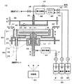
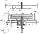
図1は本発明の1実施形態に係る無電解メッキ装置10の構成を示す一部断面図である。
無電解メッキ装置10は、処理液を用いて基板たるウエハWへの無電解メッキ処理、その前処理(活性化処理を含む)、後処理(洗浄処理を含む)を行うことができる。
Hereinafter, an electroless plating apparatus according to an embodiment of the present invention will be described in detail with reference to the drawings.
FIG. 1 is a partial cross-sectional view showing a configuration of an
The
無電解メッキに用いる薬液(メッキ液)として以下の材料を混合し純水に溶解したものを用いることができる。
1)金属塩:メッキ膜を構成する金属イオンを供給する材料であり、メッキ膜が銅の場合には、例えば、硫酸銅、硝酸銅、塩化銅である。メッキ膜がコバルト合金の場合には、例えば、硫酸コバルト、塩化コバルトを、メッキ膜がニッケル合金の場合には、例えば、硫酸ニッケル、塩化ニッケル、硝酸ニッケルを金属塩として用いることができる。
2)錯化剤:強アルカリ性下において、金属イオンが水酸化物として沈殿しないように、金属を錯体化して液中での安定性を向上させるための材料であり、例えば、アミン系材料としてHEDTA、EDTA、ED、有機系材料としてクエン酸、酒石酸、グルコン酸を用いることができる。
3)還元剤:金属イオンを触媒的に還元析出させるための材料であり、例えば、次亜塩素酸、グルオキシル酸、塩化第二スズ、水素化ホウ素化合物、硝酸第二コバルト、次亜リン酸、塩化チタンを用いることができる。
4)安定剤:酸化物(メッキ膜が銅の場合には酸化第二銅)の不均一性に起因するメッキ液の自然分解を防止する材料であり、窒素系の材料として、例えば、1価の銅と優先的に錯体を形成するビビルジル、シアン化合物、チオ尿素、0−フェナントロリン、ネオブロインを用いることができる。
5)pH緩衝剤:メッキ液の反応が進んだときのpHの変化を抑制するための材料であり、例えば、ホウ酸、炭酸、オキシカルボン酸を用いることができる。
6)添加剤:添加剤にはメッキ膜の析出の促進、抑制を行う材料や、表面またはメッキ膜の改質を行う材料がある。
・メッキ膜の析出速度を抑制し、メッキ液の安定化およびメッキ膜の特性を改善するための材料としては、硫黄系の材料として、例えば、チオ硫酸、2−MBTを用いることができる。
・メッキ液の表面張力を低下させ、ウエハWの面上にメッキ液が均一に配置されるようにするための材料としては、界面活性剤のノニオン系材料として例えばポリアルキレングリコール、ポリエチレングリコールを用いることができる。
As a chemical solution (plating solution) used for electroless plating, a solution in which the following materials are mixed and dissolved in pure water can be used.
1) Metal salt: A material for supplying metal ions constituting the plating film. When the plating film is copper, for example, copper sulfate, copper nitrate, and copper chloride. When the plating film is a cobalt alloy, for example, cobalt sulfate and cobalt chloride can be used as the metal salt, and when the plating film is a nickel alloy, for example, nickel sulfate, nickel chloride, and nickel nitrate can be used as the metal salt.
2) Complexing agent: A material for complexing metals to improve stability in liquid so that metal ions do not precipitate as hydroxides under strong alkalinity. For example, HEDTA is used as an amine material. Citric acid, tartaric acid and gluconic acid can be used as EDTA, ED and organic materials.
3) Reducing agent: a material for catalytically reducing and precipitating metal ions, such as hypochlorous acid, glyoxylic acid, stannic chloride, borohydride compounds, cobaltous nitrate, hypophosphorous acid, Titanium chloride can be used.
4) Stabilizer: A material that prevents the natural decomposition of the plating solution due to non-uniformity of oxide (cupric oxide when the plating film is copper). Bivirdil, cyanide, thiourea, 0-phenanthroline, and neobroin, which form a complex preferentially with copper, can be used.
5) pH buffering agent: A material for suppressing a change in pH when the reaction of the plating solution proceeds. For example, boric acid, carbonic acid, or oxycarboxylic acid can be used.
6) Additives: Additives include materials that promote and inhibit deposition of the plating film, and materials that modify the surface or the plating film.
For example, thiosulfuric acid or 2-MBT can be used as a sulfur-based material as a material for suppressing the deposition rate of the plating film and stabilizing the plating solution and improving the characteristics of the plating film.
As a material for reducing the surface tension of the plating solution so that the plating solution is uniformly disposed on the surface of the wafer W, for example, polyalkylene glycol or polyethylene glycol is used as a nonionic material for the surfactant. be able to.
前述の最小温調経過時間Tmin、最大温調経過時間Tmaxはメッキ液の組成、および温度によって異なってくる。
例えば、CoWBメッキ膜用のメッキ液で液温が60℃のとき、最小温調経過時間Tmin、最大温調経過時間Tmaxはそれぞれ、10分、180分程度である。また、CoWPメッキ膜用のメッキ液で液温が60℃のとき、最小温調経過時間Tmin、最大温調経過時間Tmaxはそれぞれ、10分、100分程度である。
The minimum temperature adjustment elapsed time Tmin and the maximum temperature adjustment elapsed time Tmax are different depending on the composition and temperature of the plating solution.
For example, when the liquid temperature is 60 ° C. with a plating solution for a CoWB plating film, the minimum temperature adjustment elapsed time Tmin and the maximum temperature adjustment elapsed time Tmax are about 10 minutes and 180 minutes, respectively. Further, when the temperature of the plating solution for the CoWP plating film is 60 ° C., the minimum temperature adjustment elapsed time Tmin and the maximum temperature adjustment elapsed time Tmax are about 10 minutes and 100 minutes, respectively.
図1に示すように無電解メッキ装置10は、ベース11、モータ12、基板保持部たるウエハチャック20、上部プレート30、下部プレート40、カップ50、ノズルアーム61,62、液供給機構80、制御部90を有する。
ここで、モータ12、ウエハチャック20、上部プレート30、下部プレート40、カップ50、ノズルアーム61,62は、直接的あるいは間接的にベース11に接続され、ベース11と一体となって移動等が行われる。
As shown in FIG. 1, the
Here, the
ウエハチャック20は、ウエハWを保持・固定するものであり、ウエハ保持爪21、ウエハチャック底板23、ウエハチャック支持部24から構成され、基板保持部として機能する。
ウエハ保持爪21は、ウエハチャック底板23の外周上に複数個配置され、ウエハWを保持、固定する。
ウエハチャック底板23は、ウエハチャック支持部24の上面に接続された略円形の平板であり、カップ50の底面上に配置されている。
ウエハチャック支持部24は、略円筒形状であり、ウエハチャック底板23に設けられた円形状の開口部に接続され、かつモータ12の回転軸を構成する。この結果、モータ12を駆動することで、ウエハWを保持したままで、ウエハチャック20を回転させることができる。
The
A plurality of
The wafer
The
上部プレート30は、ウエハWの上面に対向して配置された略円形の平板形状であり、ウエハWの上面への薬液、純水等の処理液の供給、および処理液の加熱を行う。
上部プレート30は、ヒータH(図示せず)、処理液吐出口31、処理液流入部32、温度測定機構33を有し、昇降機構38に接続されている。
ヒータHは上部プレート30を加熱するための電熱線等の加熱手段である。ヒータHは温度測定機構33での温度測定結果に対応して、上部プレート30、ひいてはウエハWが所望の温度に保持されるように(例えば、室温から90℃程度の範囲)、制御部90により発熱量が制御される。
The
The
The heater H is a heating means such as a heating wire for heating the
処理液吐出口31は、上部プレート30の下面に形成され、処理液流入部32から流入した処理液を吐出するものであり、メッキ液吐出部として機能する。
上部プレート30の下面がウエハWの上面と近接して対応した状態で処理液吐出口31より処理液を吐出することで、上部プレート30とウエハWの間に処理液の層が形成される。処理液の吐出を続けると、この処理液は上部プレート30の周辺から流出する。
図1では処理液吐出口31を単一としているが、処理液吐出口31を複数配置することで、処理液の供給と基板の温度の均一化を図ることができる。
The processing
By discharging the processing liquid from the processing
In FIG. 1, the processing
処理液流入部32は上部プレート30の上面側にあって、処理液が流入し、流入した処理液を処理液吐出口31へと導く。処理液流入部32に流入する処理液は、純水、薬液1,2を切り替えて用いることができる。また、後述するミキシングボックス85で混合された薬液1,2(場合により、他の薬液を含む複数の薬液を混合して)、あるいは後述する熱交換器86により温度調節された薬液1,2を処理液流入部32に流入させることもできる。
温度測定機構33は、上部プレート30に埋め込まれた熱電対等の温度測定手段であり、上部プレート30の温度を測定する。
The processing
The
昇降機構38は、間隔調節部として機能するものであり、上部プレート30に接続され、上部プレート30をウエハWに対向した状態で上下に昇降し、例えば、ウエハWとの間隔を0.1〜500mmの間で制御することができる。
無電解メッキ中においてはウエハWと上部プレート30を近接させ(例えば、ウエハWと上部プレート30との間隔が2mm以下)、これらのギャップの空間の大きさを制限し、ウエハWの面上に供給される処理液の均一化、および使用量の低減を図ることができる。
The elevating
During the electroless plating, the wafer W and the
下部プレート40は、ウエハWの下面に対向して配置された略円形の平板形状であり、ウエハWに近接した状態でその下面へ加熱された純水の供給を行うことで、ウエハWを適宜に加熱できる。
下部プレート40は、その上面の中央に処理液吐出口41が形成され、支持部42で支持されている。
処理液吐出口41は、支持部42内を通過した処理液を吐出する。処理液は純水を用いることができる。
支持部42は、モータ12を貫通し、間隔調節部たる昇降機構(図示せず)に接続されている。昇降機構を動作することで、支持部42、ひいては下部プレート40を上下に昇降することができる。
The
The
The processing
The
カップ50は、ウエハチャック20をその中に保持し、かつウエハWの処理に用いられた処理液を受け止め排出するものであり、カップ側部51,カップ底板52,廃液管53を有する。
カップ側部51は、その内周がウエハチャック20の外周に沿う略円筒形であり、その上端がウエハチャック20の保持面の上方近傍に位置している。
カップ底板52は,カップ側部51の下端に接続され、モータ12に対応する位置に開口部を有し、その開口部に対応する位置にウエハチャック20が配置されている。
廃液管53は、カップ底板52に接続され、カップ50から廃液(ウエハWを処理した処理液)を無電解メッキ装置10が設置された工場の廃液ライン等へと排出するための配管である。
カップ50は、図示しない昇降機構に接続され、ベース11とウエハWに対して上下に移動することができる。
The
The
The
The
The
ノズルアーム61,62は、ウエハWの上面近傍に配置され、その先端の開口部から処理液、エアー等の流体を吐出する。吐出する流体は純水、メッキ液、窒素ガスを適宜に選択することができる。ノズルアーム61,62にはそれぞれ、ウエハWの中央に向かう方向にノズルアーム61,62を移動させる移動機構(図示せず)が接続されている。ウエハWに流体を吐出する場合にはノズルアーム61,62がウエハWの上方に移動され、吐出が完了するとウエハWの外周の外に移動される。なお、ノズルアームの数は吐出する薬液の量、種類により単数もしくは3本以上にすることも可能である。
The
液供給機構80は、上部プレート30,下部プレート40に処理液等を供給するものであり、処理液タンク81〜83、ポンプP1〜P3、バルブV1〜V5、ミキシングボックス85、熱交換器86,87から構成される。上部プレート30には、薬液1,2を適宜にミキシングボックス85で混合し、熱交換器86で温度調節して送ることができる。下部プレート40には、熱交換器87で温度調節された純水を適宜に送ることができる。
なお、図1は薬液1,2と2種類の薬液を用いた場合を表しているが、処理タンク、ポンプ、バルブの数はミキシングボックス85で混合する薬液に数に応じて適宜に設定できる。
The
Although FIG. 1 shows the case where two types of chemical solutions 1 and 2 are used, the number of processing tanks, pumps, and valves can be appropriately set according to the number of chemical solutions mixed in the
処理液タンク81,82,83は、それぞれ、純水、薬液1,2を保持するタンクである。
ポンプP1〜P3は、処理液タンク81〜83から処理液を吸い出す吸引装置である。なお、処理液タンク81〜83をそれぞれ加圧することで、処理液タンク82〜84からの送液を行ってもよい。
バルブV1〜V3は配管の開閉を行い、処理液の供給および供給停止を行う。また、バルブV4は、上部プレート30に室温の(加熱されない)純水を供給するためのものである。
バルブV5は、熱交換器86から処理液を排出するためのものであり、メッキ液排出部として機能する。この排出は、例えば、熱交換器86中のメッキ液の温調経過時間が所定範囲(最大温調経過時間)を越えたメッキ液をメッキ処理に用いないようにするために行われる。温調経過時間が最大温調経過時間を越えたメッキ液をバルブV5より廃液ラインへと排出し、これに替えて、未加熱のメッキ液を熱交換器86で加熱してメッキ処理に用いる。
ミキシングボックス85は、処理液タンク83,84から送られた薬液1,2を混合するための容器である。
The
The pumps P1 to P3 are suction devices that suck out the processing liquid from the processing
The valves V1 to V3 open and close the piping, and supply and stop supply of the processing liquid. The valve V4 is for supplying pure water at room temperature (not heated) to the
The valve V5 is for discharging the processing liquid from the
The
熱交換器86,87は、それぞれ処理液(薬液、純水等)を加熱するための加熱装置であり、液温調節部として機能する。即ち、熱交換器86は、薬液を加熱し、その液温が設定温度付近となるように温度調節を行う。
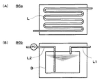
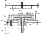
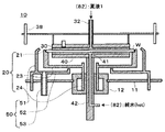
図2(A),(B)はそれぞれ、熱交換器86の一例を表す模式図である。なお、熱交換器87も同様の構成を採用することができる。
図2(A)では熱交換器86aの内部に配管Lが配置され、この配管L中の処理液が加熱され、処理液流入部32へと導かれる。
また、図2(B)では、熱交換器86bの内部に液槽Bが配置され、液槽B中の処理液が加熱される。液槽Bで加熱された処理液は、ポンプP0によって液槽Bから排出され処理液流入部32へと導かれる。
The
FIGS. 2A and 2B are schematic diagrams illustrating an example of the
In FIG. 2A, a pipe L is disposed inside the
Moreover, in FIG. 2 (B), the liquid tank B is arrange | positioned inside the
図2(A),(B)いずれの場合でも処理液の加熱は種々の加熱機構(図示せず)を用いて行える。例えば、配管L、液槽Bを外部からヒータ(例えば、電熱線)、ランプ(例えば、赤外線ランプ)、温水等で加熱することができる。また、配管L、液槽Bの内部から処理液を加熱してもよい。例えば、液槽B内に設置した投げ込みヒータを用いることができる。
なお、熱交換器86、87には、処理液の液温を測定する図示しない温度測定機構(例えば、熱電対)が備えられる。
In either case of FIGS. 2A and 2B, the treatment liquid can be heated using various heating mechanisms (not shown). For example, the pipe L and the liquid tank B can be heated from the outside with a heater (for example, heating wire), a lamp (for example, an infrared lamp), hot water, or the like. Further, the treatment liquid may be heated from the inside of the pipe L and the liquid tank B. For example, a throwing heater installed in the liquid tank B can be used.
The
制御部90は、無電解メッキ装置10全体の動作を制御する制御装置であり、コンピュータにより構成できる。即ち、コンピュータの中央演算装置(CPU:Central Processing Unit)とソフトウェアの組み合わせにより、制御部90を構成できる。中央演算装置がソフトウェアにより動作することで、制御部90として機能する。
The
制御部90は、例えば次の(1)〜(4)に示すように無電解メッキ装置10を制御する。
(1)液供給機構80の制御
液供給機構80による処理液の供給、熱交換器86,87による処理液の温度調節を制御する。なお、この詳細は後述する。
(2)ノズルアーム61,62の制御
ノズルアーム61,62の移動、旋回、ノズルアーム61,62からの処理液の供給、使用済みの処理液の吸引を制御する。
(3)上部プレート30、下部プレート40の制御
上部プレート30、下部プレート40の温度調節および上下移動を制御する。
(4)ウエハチャック20の制御
ウエハチャック20(ウエハ保持爪21)によるウエハWの固定、開放、モータ12によるウエハチャック20の回転を制御する。
The
(1) Control of the
(2) Control of the
(3) Control of
(4) Control of
(メッキ液の温度調節および供給の制御の詳細)
以下、制御部90によるメッキ液の温度調節および供給の制御の詳細を説明する。既述のようにメッキ液は熱履歴が管理され、温調経過時間(メッキ液が設定温度に達してから経過した時間)が所定の範囲内のメッキ液がメッキ処理に用いられる。
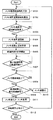
図3は、制御部90によるメッキ液の温度調節および供給の制御手順の一例を表すフロー図である。
以下、図3に基づき、メッキ液の温度調節および供給の制御手順を説明する。
(Details of temperature control and supply control of plating solution)
Hereinafter, details of temperature control and supply control of the plating solution by the
FIG. 3 is a flowchart showing an example of a control procedure of the temperature adjustment and supply of the plating solution by the
Hereinafter, the temperature adjustment and supply control procedure of the plating solution will be described with reference to FIG.
(1)メッキ処理開始時刻の予測(ステップS101)
ウエハWへのメッキ処理を開始可能な時刻(処理開始時刻)T0を予測する。ここで、「メッキ処理を開始可能」とは、ウエハWが無電解メッキ装置10に設置され、かつメッキ前処理が行われた状態を意味する。この予測は、以下a〜dのようにして行える。
(1) Prediction of plating processing start time (step S101)
A time (processing start time) T0 at which the plating process on the wafer W can be started is predicted. Here, “the plating process can be started” means that the wafer W is installed in the
a.ウエハWが無電解メッキ装置10に設置され、かつメッキ前処理が完了しているときは、直ぐにもメッキ処理が可能である。このときは、このことが確認されたときの時刻を処理開始時刻T0とする。
b.ウエハWが無電解メッキ装置10に設置されているが、メッキ前処理が完了していないときは、この前処理が完了するときを処理開始時刻T0とする。具体的には、前処理を開始した時刻(または前処理を開始する予定の時刻)に前処理に要する時間を加算することで、処理開始時刻T0を導出できる。
a. When the wafer W is installed in the
b. When the wafer W is installed in the
c.無電解メッキ装置10に設置されているウエハWがメッキ処理中の場合には、次の(未処理の)ウエハWの処理開始時刻T0を予測する。例えば、次のウエハWの設置が確認された時刻に前処理に要する時間を加算することで、処理開始時刻T0を算出できる。また、処理中のウエハWのメッキ処理開始時刻にメッキ処理およびその後の後処理に要する時間および新たなウエハWの前処理時間を加算することで、処理開始時刻T0を算出してもよい。
d.ウエハWが無電解メッキ装置10に設置されていないときは、ウエハWが設置される予定の時刻に前処理に要する時間を加算することで、処理開始時刻T0を導出できる。この場合、ウエハWが設置される時刻を導出する代わりに、ウエハWが設置されていることが確認された時刻に前処理に要する時間を加算することで、処理開始時刻T0を導出できる。
e.なお、以上のようにその時々で処理開始時刻の予測を行う代わりに、一連のウエハWの処理開始時間それぞれを制御部90に予め入力、記憶させておいてもよい。この記憶は制御部90の記憶部(図示せず)が行う。
c. When the wafer W installed in the
d. When the wafer W is not installed in the
e. As described above, instead of predicting the processing start time from time to time, each processing start time of a series of wafers W may be input and stored in the
(2)メッキ液昇温開始時刻の算出(ステップS102)
メッキ処理開始時刻T0に基づきメッキ液昇温開始時刻T1を算出する。この算出は、メッキ処理開始時刻T0からメッキ液昇温時間Th(メッキ液の昇温を開始してから所定の温度に達するまでに要する時間)およびメッキ液最小温調経過時間Tminを減算することで行える(T1=T0−(Th+Tmin))。
(2) Calculation of plating solution temperature rise start time (step S102)
A plating solution temperature rise start time T1 is calculated based on the plating process start time T0. This calculation is performed by subtracting the plating solution temperature increase time Th (the time required to reach a predetermined temperature after starting the temperature increase of the plating solution) and the plating solution minimum temperature adjustment elapsed time Tmin from the plating processing start time T0. (T1 = T0− (Th + Tmin)).
(3)メッキ液昇温開始時刻の到来を待って、メッキ液の昇温を開始する(ステップS103,104)。
ここで、メッキ前処理が完了したウエハWが無電解メッキ装置10に設置されているときには、直ちに昇温が開始される((1)a.の場合)。
(4)メッキ液が設定温度に到達する(ステップS105)。
制御部90は熱交換器86内の温度測定機構(図示せず)によってメッキ液の温度を測定し設定温度に到達したことを確認する。
(3) Waiting for the arrival of the plating solution temperature rise start time, the temperature rise of the plating solution is started (steps S103 and S104).
Here, when the wafer W on which the plating pretreatment has been completed is installed in the
(4) The plating solution reaches the set temperature (step S105).
The
(5)メッキ液が設定温度に到達したことが確認されたら、メッキ液の温調経過時間Tの計時を開始し(ステップS106)、温調経過時間Tが最小温調経過時間Tmin以上になるまで待つ(ステップS107)。
(6)ウエハWの前処理が完了しているかを確認する。完了していなければ完了するまで待つ(ステップS108)。
(5) When it is confirmed that the plating solution has reached the set temperature, the timing of the temperature adjustment elapsed time T of the plating solution is started (step S106), and the temperature adjustment elapsed time T becomes equal to or greater than the minimum temperature adjustment elapsed time Tmin. (Step S107).
(6) Check whether the pre-processing of the wafer W is completed. If not completed, it waits until it is completed (step S108).
(7)温調経過時間Tが最大温調経過時間Tmax以下であるか否かを確認する(ステップS109)。この判断がNoなら、バルブV5を開いて熱交換器86内のメッキ液を廃液ラインに排出し新たなメッキ液を注入して(ステップS110)、ステップS104に戻って新たなメッキ液の昇温が行われる。
ステップS109での判断がYesなら、熱交換器86で加熱されたメッキ液を処理液流入部32経由で処理液吐出口31から吐出し、ウエハWに供給する。この結果、ウエハWのメッキ処理が行われ、ウエハW上にメッキ膜が形成される(ステップS111)。
(8)次に処理するウエハWがあればステップS101に戻って処理が繰り返され、そうでないなら一連の処理を完了する(ステップS112)。
(7) It is confirmed whether or not the temperature adjustment elapsed time T is equal to or less than the maximum temperature adjustment elapsed time Tmax (step S109). If this judgment is No, the valve V5 is opened, the plating solution in the
If the determination in step S109 is Yes, the plating liquid heated by the
(8) If there is a wafer W to be processed next, the process returns to step S101 and the process is repeated. If not, a series of processes is completed (step S112).
以上の処理手順ではステップS101,S102で算出されたメッキ液の昇温開始予定時刻が正確なものであれば、ステップS108でメッキ前処理が完了したときの温調経過時間Tは最小温調経過時間Tminに等しくなる。即ち、この場合にはステップS109での確認は不要である。
しかしながら、算出された昇温開始予定時刻の誤差等の理由でステップS108での温調経過時間Tが最大温調経過時間Tmaxを越えることもあり得るので、ステップS109で確認を行っている。例えば、メッキ液昇温時間Thが予定より短かったりすることもあり得る。
以上のように、ステップS101,102での確認、算出結果が正確なものであれば、ステップS109,S110を省略することができる。
In the above processing procedure, if the estimated temperature rise start time of the plating solution calculated in steps S101 and S102 is accurate, the temperature adjustment elapsed time T when the plating pretreatment is completed in step S108 is the minimum temperature adjustment elapsed time. It becomes equal to time Tmin. That is, in this case, confirmation in step S109 is not necessary.
However, because the temperature adjustment elapsed time T in step S108 may exceed the maximum temperature adjustment elapsed time Tmax due to an error in the calculated temperature rise start scheduled time, etc., confirmation is performed in step S109. For example, the plating solution heating time Th may be shorter than planned.
As described above, if the confirmation and calculation results in steps S101 and S102 are accurate, steps S109 and S110 can be omitted.
場合によりステップS101〜S103を省略することも可能である。この場合には、ウエハWの処理状況に基づく予測を行わないため、温調経過時間Tが最大温調経過時間Tmaxを越え、メッキ液が廃棄される可能性が大きくなるが(ステップS109、S110)、このようなロスがさほど問題としなければ差し支えない。 In some cases, steps S101 to S103 can be omitted. In this case, since prediction based on the processing state of the wafer W is not performed, the temperature adjustment elapsed time T exceeds the maximum temperature adjustment elapsed time Tmax, and the possibility that the plating solution is discarded increases (steps S109 and S110). ) If such a loss does not matter so much, it does not matter.
以上から判るように図3で示した制御内容はウエハWのメッキ液処理が可能となる時刻(処理開始時刻)を予測し、この処理開始時刻にメッキ液の最小温調経過時間が合致するようにして、全体としての処理時間の短縮、かつメッキ液の有効利用(メッキ液の廃棄防止)を図っている。さらに、この予測に狂いが生じることに備えてステップS109,S110の温調経過時間の確認・メッキ液の廃棄処理を行っている。 As can be seen from the above, the control content shown in FIG. 3 predicts the time (processing start time) at which the plating solution processing of the wafer W can be performed, and the minimum temperature adjustment elapsed time of the plating solution matches the processing start time. Thus, the processing time as a whole is shortened and the plating solution is effectively used (plating solution is prevented from being discarded). Further, in preparation for the occurrence of an error in the prediction, the temperature control elapsed time is confirmed and the plating solution is discarded in steps S109 and S110.
(無電解メッキ工程の詳細)
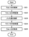
図4は、無電解メッキ装置10を用いてウエハWに対して無電解メッキを行う手順全体の一例を表すフロー図である。また、図5から8は、図4に表した手順で無電解メッキを行った場合において、各工程における無電解メッキ装置10の状態を表した一部断面図である。以下、図4〜8を用いてこの手順を詳細に説明する。
(Details of electroless plating process)
FIG. 4 is a flowchart showing an example of the entire procedure for performing electroless plating on the wafer W using the
(1)ウエハWの保持(ステップS21および図5)
ウエハWがウエハチャック20上に保持される。例えば、ウエハWをその上面で吸引した図示しない吸引アーム(基板搬送機構)がウエハチャック20上にウエハWを載置する。そして、ウエハチャック20のウエハ保持爪21によってウエハWを保持・固定する。なお、カップ50を降下させることで、ウエハWの上面より下で吸引アームを水平方向に動かすことができる。
(1) Holding wafer W (step S21 and FIG. 5)
Wafer W is held on
(2)ウエハWの前処理(ステップS22および図6)
ウエハWを回転させ、ウエハWの上面にノズルアーム61またはノズルアーム62から前処理液を供給することで、ウエハWの前処理が行われる。
ウエハWの回転はモータ12によりウエハチャック20を回転することで行われる。
ノズルアーム61,62いずれかまたは双方がウエハWの上方に移動し、前処理液を吐出する。
(2) Pre-processing of wafer W (step S22 and FIG. 6)
By rotating the wafer W and supplying the pretreatment liquid from the
The wafer W is rotated by rotating the
Either one or both of the
前処理としてはウエハW、メッキ膜の性質等に応じた処理が考えられる。例えば、前処理液に活性化処理液を用いた活性化処理、前処理液に純水を用いた洗浄処理、あるいはこれらの組み合わせが考えられる。ウエハWの乾燥も含めても良い。
即ち、本実施形態では、無電解メッキ装置10にウエハWを設置した後、ウエハW上にメッキ液を供給してメッキ処理を開始する前に行う処理一般を広義な前処理を意味するものとする。
As pre-processing, processing according to the properties of the wafer W, the plating film, etc. can be considered. For example, an activation treatment using an activation treatment solution as a pretreatment solution, a cleaning treatment using pure water as a pretreatment solution, or a combination thereof can be considered. The drying of the wafer W may be included.
That is, in this embodiment, the general processing performed after the wafer W is set in the
具体的には、このような広義な意味での前処理に相当する処理には以下1)〜3)が挙げられる。
1)ウエハWの洗浄・乾燥
・ノズルアーム61,62から供給された純水によるウエハWの洗浄
・ウエハWの乾燥(ウエハWを高速で回転することによる、ウエハW上の純水の除去)
2)ウエハWの活性化処理
ウエハWの上面にノズルアーム61またはノズルアーム62から活性化処理液を供給することによるウエハWの活性化処理
Specifically, the following 1) to 3) are included in the processing corresponding to the preprocessing in such a broad sense.
1) Cleaning and drying of wafer W Cleaning of wafer W with pure water supplied from
2) Activation process of wafer W Activation process of wafer W by supplying an activation process liquid from
3)ウエハWの加熱
ウエハWをメッキ液の反応に適した温度に保つためにウエハWを加熱する。
下部プレート40を加熱してウエハWの下面に近接させ、処理液吐出口41から液供給機構80で加熱された純水を供給する。この加熱された純水は、ウエハW下面と下部プレート40上面との間に充満し、ウエハWを加熱する。
ウエハWの加熱は他の手段で行っても差し支えない。例えば、ヒータやランプの輻射熱によってウエハWを加熱しても差し支えない。また、場合により、加熱した下部プレート40をウエハWに接触することでウエハWを加熱してもよい。
3) Heating of wafer W In order to keep the wafer W at a temperature suitable for the reaction of the plating solution, the wafer W is heated.
The
The wafer W may be heated by other means. For example, the wafer W may be heated by the radiant heat of a heater or a lamp. In some cases, the wafer W may be heated by bringing the heated
(3)メッキ液の供給(ステップS23および図7)。
上部プレート30を加熱してウエハWの上面に近接させ、処理液吐出口31からメッキ用の薬液(メッキ液)を供給する。供給されたメッキ液は、ウエハW上面と上部プレート30下面との間に充満し、カップ50へと流出する。
このとき、供給されるメッキ液は熱交換器86および加熱された上部プレート30によって温度調節される(一例として、室温から90℃程度の範囲)。また、供給されるメッキ液は、図3に示したような制御手順により熱履歴が制御されている。即ち、供給されるメッキ液は温調経過時間が最小温調経過時間以上、最大温調経過時間以下となっている。このようにメッキ液の熱履歴が制御されているので、ウエハWへのメッキ膜の形成が安定して行われる。
上部プレート30の加熱は先のステップS1〜S6のどこかで先行して行うことができる。上部プレート30の加熱を他の工程と並行して行うことでウエハWの処理時間を低減できる。
(3) Supply of plating solution (step S23 and FIG. 7).
The
At this time, the temperature of the supplied plating solution is adjusted by the
Heating of the
(4)ウエハWの後処理(ステップS24および図8)
本実施形態ではウエハWにメッキ処理を行った後の処理一般を後処理と称す。後処理には、例えば、ウエハWの洗浄、乾燥を挙げることができ、図8はウエハWを洗浄している状態を表している。
ウエハWの洗浄は、バルブV4を開いて処理液流入部32に純水を注入し、上部プレート30の処理液吐出口31から純水を吐出させることで行える。
このウエハWの洗浄中にウエハWを回転することで、ウエハWの洗浄の均一性を向上することができる。
ウエハWの洗浄後にウエハWを回転することでウエハWの乾燥を行える。
(4) Post-processing of wafer W (step S24 and FIG. 8)
In the present embodiment, the general processing after the plating process is performed on the wafer W is referred to as post-processing. Post-processing can include, for example, cleaning and drying of the wafer W, and FIG. 8 shows a state in which the wafer W is being cleaned.
The wafer W can be cleaned by opening the valve V4, injecting pure water into the processing
By rotating the wafer W during the cleaning of the wafer W, the uniformity of the cleaning of the wafer W can be improved.
The wafer W can be dried by rotating the wafer W after the cleaning of the wafer W.
(5)ウエハWの除去(ステップS25および図5)。
ウエハWの後処理が終了した後、ウエハチャック20によるウエハWの保持が停止される。その後、図示しない吸引アーム(基板搬送機構)によりウエハWがウエハチャック20上から取り去られる。
(5) Removal of wafer W (step S25 and FIG. 5).
After the post-processing of the wafer W is completed, the holding of the wafer W by the
(その他の実施形態)
本発明の実施形態は既述の実施形態には限られず、拡張、変更できる。拡張、変更した実施形態も本発明の技術的範囲に含まれる。
(1)例えば、基板としてウエハW以外の例えばガラス板等を利用することができる。
(2)基板への処理液(メッキ液を含む)の供給は必ずしも連続的に行う必要はなく、ある程度間欠的に行っても差し支えない。供給されるメッキ液の温調経過時間が最小温調経過時間、最大温調経過時間の範囲内であれば、メッキ液を間欠的に供給してもよい。
(3)基板への処理液(メッキ液を含む)の供給をノズルアームから行ってもよい。
(Other embodiments)
Embodiments of the present invention are not limited to the above-described embodiments, and can be expanded and modified. Extended and modified embodiments are also included in the technical scope of the present invention.
(1) For example, a glass plate other than the wafer W can be used as the substrate.
(2) The treatment liquid (including the plating liquid) is not necessarily supplied continuously to the substrate, and may be intermittently performed to some extent. If the temperature adjustment elapsed time of the supplied plating solution is within the range of the minimum temperature adjustment elapsed time and the maximum temperature adjustment elapsed time, the plating solution may be supplied intermittently.
(3) The treatment liquid (including the plating liquid) may be supplied to the substrate from the nozzle arm.
10 無電解メッキ装置
11 ベース
12 モータ
20 ウエハチャック
21 ウエハ保持爪
23 ウエハチャック底板
24 ウエハチャック支持部
30 上部プレート
31 処理液吐出口
32 処理液流入部
33 温度測定機構
38 昇降機構
40 下部プレート
41 処理液吐出口
42 支持部
50 カップ
51 カップ側部
52 カップ底板
53 廃液管
61,62 ノズルアーム
80 液供給機構
81,82,83 処理液タンク
83,84 処理液タンク
85 ミキシングボックス
86,87 熱交換器
90 制御部
DESCRIPTION OF
Claims (6)
メッキ液の液温を調節する液温調節部と,
前記液温調節部により所定の設定温度に液温が調節されてからの経過時間が第1の所定の時間以上,第2の所定の時間以下のメッキ液を吐出するメッキ液吐出部と,
前記経過時間が前記第2の所定の時間を越えたメッキ液を前記液温調節部から排出するメッキ液排出部と,
を具備することを特徴とする無電解メッキ装置。 A substrate holder for holding the substrate;
A liquid temperature control unit for adjusting the temperature of the plating solution;
A plating solution discharge unit for discharging a plating solution whose elapsed time from the time when the solution temperature is adjusted to a predetermined set temperature by the solution temperature adjusting unit is not less than a first predetermined time and not more than a second predetermined time;
A plating solution discharger for discharging the plating solution whose elapsed time exceeds the second predetermined time from the solution temperature control unit;
An electroless plating apparatus comprising:
をさらに具備することを特徴とする請求項1記載の無電解メッキ装置。 No of claim 1, wherein said elapsed time, further comprising a plating solution supply part for supplying the plating solution to the liquid temperature adjusting unit plating liquid is discharged beyond the second predetermined time Electroplating equipment.
基板へのメッキ処理を開始する処理開始時間に基づき,液温調節を開始する液温調節開始時間を算出する液温調節開始時間算出部と,
前記液温調節開始時間算出部で算出された液温調節開始時間に基づき,メッキ液の液温の調節を開始する液温調節部と,
前記液温調節部により所定の設定温度に液温が調節されてからの経過時間が第1の所定の時間以上,第2の所定の時間以下のメッキ液を吐出するメッキ液吐出部と,
を具備することを特徴とする無電解メッキ装置。 A substrate holder for holding the substrate;
Based on the processing start time to start plating to the substrate, and the liquid temperature adjusting start time calculating unit for calculating a liquid temperature adjusting start time for starting the liquid temperature regulation,
Based on the liquid temperature adjustment start time calculated by the liquid temperature adjustment start time calculation unit, a liquid temperature adjustment unit that starts adjusting the liquid temperature of the plating solution;
A plating solution discharge unit for discharging a plating solution whose elapsed time from the time when the solution temperature is adjusted to a predetermined set temperature by the solution temperature adjusting unit is not less than a first predetermined time and not more than a second predetermined time;
Electroless plating apparatus characterized and including child a.
ことを特徴とする請求項3記載の無電解メッキ装置。 The liquid temperature adjustment start time calculating unit includes a subtracting unit that subtracts the liquid temperature adjustment required time and the first time required to bring the plating solution to the predetermined set temperature from the processing start time. The electroless plating apparatus according to claim 3 .
基板へのメッキ処理を開始する処理開始時間に基づき,メッキ液の液温調節を開始する液温調節開始時間を算出するステップと,
前記算出された液温調節開始時間に基づき,メッキ液の液温調節を開始するステップと,
を具備することを特徴とする無電解メッキ方法。 A step of performing a plating process by discharging a plating solution having a time elapsed from the time when the liquid temperature is adjusted to a predetermined set temperature to a time equal to or longer than a first predetermined time and equal to or shorter than a second predetermined time ;
Calculating a liquid temperature adjustment start time for starting the liquid temperature adjustment of the plating solution based on a process start time for starting the plating process on the substrate;
Starting the liquid temperature adjustment of the plating solution based on the calculated liquid temperature adjustment start time;
An electroless plating method comprising:
ことを特徴とする請求項5記載の無電解メッキ方法。 The step of calculating the liquid temperature adjustment start time has a step of subtracting the liquid temperature adjustment required time and the first elapsed time required to bring the plating solution to the predetermined set temperature from the processing start time. The electroless plating method according to claim 5 .
Priority Applications (1)
| Application Number | Priority Date | Filing Date | Title |
|---|---|---|---|
| JP2003294251A JP4339045B2 (en) | 2003-08-18 | 2003-08-18 | Electroless plating apparatus and electroless plating method |
Applications Claiming Priority (1)
| Application Number | Priority Date | Filing Date | Title |
|---|---|---|---|
| JP2003294251A JP4339045B2 (en) | 2003-08-18 | 2003-08-18 | Electroless plating apparatus and electroless plating method |
Publications (2)
| Publication Number | Publication Date |
|---|---|
| JP2005060792A JP2005060792A (en) | 2005-03-10 |
| JP4339045B2 true JP4339045B2 (en) | 2009-10-07 |
Family
ID=34370865
Family Applications (1)
| Application Number | Title | Priority Date | Filing Date |
|---|---|---|---|
| JP2003294251A Expired - Lifetime JP4339045B2 (en) | 2003-08-18 | 2003-08-18 | Electroless plating apparatus and electroless plating method |
Country Status (1)
| Country | Link |
|---|---|
| JP (1) | JP4339045B2 (en) |
Families Citing this family (9)
| Publication number | Priority date | Publication date | Assignee | Title |
|---|---|---|---|---|
| US8069813B2 (en) * | 2007-04-16 | 2011-12-06 | Lam Research Corporation | Wafer electroless plating system and associated methods |
| JP5105833B2 (en) * | 2005-12-02 | 2012-12-26 | 東京エレクトロン株式会社 | Electroless plating apparatus, electroless plating method, and computer-readable storage medium |
| KR20070058310A (en) * | 2005-12-02 | 2007-06-08 | 도쿄 엘렉트론 가부시키가이샤 | Electroless Plating Apparatus and Electroless Plating Method |
| JP4571208B2 (en) * | 2008-07-18 | 2010-10-27 | 東京エレクトロン株式会社 | Semiconductor manufacturing equipment |
| JP5095786B2 (en) * | 2010-08-09 | 2012-12-12 | 東京エレクトロン株式会社 | Semiconductor manufacturing method |
| JP6526543B2 (en) * | 2015-10-28 | 2019-06-05 | 東京エレクトロン株式会社 | Plating apparatus and plating method |
| JP2021028405A (en) * | 2017-11-28 | 2021-02-25 | 東京エレクトロン株式会社 | Substrate liquid processing apparatus, substrate liquid processing method and recording medium |
| JP6926233B2 (en) * | 2017-12-01 | 2021-08-25 | 東京エレクトロン株式会社 | Substrate liquid processing equipment |
| TW202129071A (en) * | 2019-10-09 | 2021-08-01 | 日商東京威力科創股份有限公司 | Substrate liquid treatment apparatus and substrate liquid treatment method |
-
2003
- 2003-08-18 JP JP2003294251A patent/JP4339045B2/en not_active Expired - Lifetime
Also Published As
| Publication number | Publication date |
|---|---|
| JP2005060792A (en) | 2005-03-10 |
Similar Documents
| Publication | Publication Date | Title |
|---|---|---|
| JP3495033B1 (en) | Electroless plating apparatus and electroless plating method | |
| JP4547016B2 (en) | Semiconductor manufacturing apparatus and semiconductor manufacturing method | |
| US9255331B2 (en) | Apparatus for plating process | |
| KR101637170B1 (en) | Liquid treatment apparatus and liquid treatment method | |
| JP4571208B2 (en) | Semiconductor manufacturing equipment | |
| JP4339045B2 (en) | Electroless plating apparatus and electroless plating method | |
| US6875691B2 (en) | Temperature control sequence of electroless plating baths | |
| KR20140100481A (en) | Plating apparatus, plating method and storage medium | |
| JP3485561B1 (en) | Electroless plating method and electroless plating apparatus | |
| US7690324B1 (en) | Small-volume electroless plating cell | |
| JP2004115885A (en) | Electroless plating method | |
| JP5631815B2 (en) | Plating treatment method, plating treatment apparatus, and storage medium | |
| JP5095786B2 (en) | Semiconductor manufacturing method | |
| JP2015178661A (en) | electroless plating method | |
| US20040251141A1 (en) | Electroless plating apparatus and electroless plating method | |
| JP2005054257A (en) | Electroless plating method | |
| US20050164499A1 (en) | Electroless plating method and apparatus | |
| KR20140031329A (en) | Plating processing device, plating processing method, and recording medium | |
| JP2010070832A (en) | Cap metal forming method | |
| JP2006057171A (en) | Electroless plating equipment | |
| JP5331096B2 (en) | Plating equipment |
Legal Events
| Date | Code | Title | Description |
|---|---|---|---|
| A621 | Written request for application examination |
Free format text: JAPANESE INTERMEDIATE CODE: A621 Effective date: 20060801 |
|
| A977 | Report on retrieval |
Free format text: JAPANESE INTERMEDIATE CODE: A971007 Effective date: 20061225 |
|
| A131 | Notification of reasons for refusal |
Free format text: JAPANESE INTERMEDIATE CODE: A131 Effective date: 20090414 |
|
| A521 | Request for written amendment filed |
Free format text: JAPANESE INTERMEDIATE CODE: A523 Effective date: 20090603 |
|
| TRDD | Decision of grant or rejection written | ||
| A01 | Written decision to grant a patent or to grant a registration (utility model) |
Free format text: JAPANESE INTERMEDIATE CODE: A01 Effective date: 20090630 |
|
| A01 | Written decision to grant a patent or to grant a registration (utility model) |
Free format text: JAPANESE INTERMEDIATE CODE: A01 |
|
| A61 | First payment of annual fees (during grant procedure) |
Free format text: JAPANESE INTERMEDIATE CODE: A61 Effective date: 20090701 |
|
| R150 | Certificate of patent or registration of utility model |
Ref document number: 4339045 Country of ref document: JP Free format text: JAPANESE INTERMEDIATE CODE: R150 Free format text: JAPANESE INTERMEDIATE CODE: R150 |
|
| FPAY | Renewal fee payment (event date is renewal date of database) |
Free format text: PAYMENT UNTIL: 20120710 Year of fee payment: 3 |
|
| FPAY | Renewal fee payment (event date is renewal date of database) |
Free format text: PAYMENT UNTIL: 20150710 Year of fee payment: 6 |
|
| R250 | Receipt of annual fees |
Free format text: JAPANESE INTERMEDIATE CODE: R250 |
|
| R250 | Receipt of annual fees |
Free format text: JAPANESE INTERMEDIATE CODE: R250 |
|
| R250 | Receipt of annual fees |
Free format text: JAPANESE INTERMEDIATE CODE: R250 |
|
| R250 | Receipt of annual fees |
Free format text: JAPANESE INTERMEDIATE CODE: R250 |
|
| R250 | Receipt of annual fees |
Free format text: JAPANESE INTERMEDIATE CODE: R250 |
|
| R250 | Receipt of annual fees |
Free format text: JAPANESE INTERMEDIATE CODE: R250 |
|
| R250 | Receipt of annual fees |
Free format text: JAPANESE INTERMEDIATE CODE: R250 |
|
| R250 | Receipt of annual fees |
Free format text: JAPANESE INTERMEDIATE CODE: R250 |
|
| EXPY | Cancellation because of completion of term |