JP4339044B2 - Electrostatic latent image development carrier - Google Patents
Electrostatic latent image development carrier Download PDFInfo
- Publication number
- JP4339044B2 JP4339044B2 JP2003289848A JP2003289848A JP4339044B2 JP 4339044 B2 JP4339044 B2 JP 4339044B2 JP 2003289848 A JP2003289848 A JP 2003289848A JP 2003289848 A JP2003289848 A JP 2003289848A JP 4339044 B2 JP4339044 B2 JP 4339044B2
- Authority
- JP
- Japan
- Prior art keywords
- refractive index
- light
- resin
- carrier
- electrostatic latent
- Prior art date
- Legal status (The legal status is an assumption and is not a legal conclusion. Google has not performed a legal analysis and makes no representation as to the accuracy of the status listed.)
- Expired - Fee Related
Links
Images


Landscapes
- Developing Agents For Electrophotography (AREA)
Description
本発明は、トナー粒子と共に撹拌することによりトナー粒子に電荷を付与する電荷付与部材である静電潜像現像用キャリアに関する。 The present invention relates to a carrier for developing an electrostatic latent image, which is a charge imparting member that imparts a charge to toner particles by stirring with the toner particles.
電子写真の原理を用いる乾式現像方式は、摩擦帯電付与部材と摩擦させた粉体トナーを、静電潜像に静電的に付着させて可視像を形成するものである。この乾式現像方法には、トナーのみを主成分とするいわゆる一成分系現像方式と、磁性体キャリア、或いは、それらの表面を樹脂などで被覆したコートキャリアとトナーを混合して使用する、いわゆる二成分系現像方式がある。 In the dry development system using the principle of electrophotography, a visible image is formed by electrostatically adhering a powder toner rubbed with a frictional charging member to an electrostatic latent image. In this dry development method, a so-called two-component development method in which only toner is used as a main component, a magnetic carrier, or a coated carrier whose surface is coated with a resin and a toner are mixed and used. There is a component development system.
後者で用いられる二成分現像剤は、比較的大きなキャリア粒子表面上に微小なトナー粒子が両粒子の摩擦により発生した電気力により保持されている。静電潜像に近接されると、静電潜像が形成する電界により、トナー粒子はキャリア粒子との結合力に打ち勝って静電潜像上に現像されるものである。そして、現像剤は現像によって消費されたトナーを補充しながら反複使用される。従って、キャリア粒子は長時間の使用中、常にトナー粒子を所望する極性で、かつ、充分な帯電量に摩擦帯電しなければならない。 In the two-component developer used in the latter, fine toner particles are held on the surface of relatively large carrier particles by an electric force generated by friction between both particles. When close to the electrostatic latent image, the toner particles are developed on the electrostatic latent image by overcoming the binding force with the carrier particles by the electric field formed by the electrostatic latent image. The developer is used repeatedly while replenishing the toner consumed by the development. Accordingly, the carrier particles must always be triboelectrically charged with a desired polarity and a sufficient amount of charge during long-time use.
しかしながら、粒子間の衝突、粒子と現像装置内での機械的攪拌、又はこれらによる発熱で、キャリア粒子表面にトナーが融着し、いわゆるスペントトナーが生じ、キャリア粒子の帯電特性が使用時間と共に低下する。それに伴い、画像の地肌汚れやトナー飛散が生じる為、現像剤全体を取りかえる必要が生じる。
このようなスペント化を防止するため、磁性微粉体表面に、表面エネルギーの低い樹脂、例えばフッ素樹脂、シリコーン樹脂などをコートすることによりキャリアの長寿命化が図られてきた。
However, collision between particles, mechanical stirring in the particles and the developing device, or heat generated by these causes the toner to be fused to the surface of the carrier particles, so-called spent toner is generated, and the charging characteristics of the carrier particles decrease with use time. To do. As a result, the background of the image and toner scattering occur, so that the entire developer needs to be replaced.
In order to prevent such spenting, the life of the carrier has been extended by coating the surface of the magnetic fine powder with a resin having a low surface energy, such as a fluororesin or a silicone resin.
一般に、二成分現像剤において、画像濃度を上げる為に、トナー濃度を上げること、トナー帯電量を低くすること、また、キャリアの低抵抗化などが行われている。キャリアを低抵抗化する方法は、従来から幾つか検討されており、その一つに「極めて薄い樹脂コート膜を形成する」手段が講じられている。 In general, in a two-component developer, in order to increase the image density, the toner density is increased, the toner charge amount is decreased, and the resistance of the carrier is decreased. Several methods for reducing the resistance of carriers have been studied, and one of them is a means of “forming a very thin resin coat film”.
これら樹脂コート膜の厚さを測る手段は、対象が100μm以下の微粉体で有ること、樹脂コート膜が一般にサブミクロンオーダーの薄膜であること、及び光透過性の樹脂コート膜の表面が一般に荒れていること、サブストレイトである磁性微粉体の表面性が一般に荒れていることから、樹脂コート膜表面と磁性微粉体界面間の膜厚という尺度で膜厚を計測することが困難であり、従来から、磁性微粉体に対する樹脂質量を計測する質量膜厚測定法(例えば、特許文献1〜3参照)、既知のシリコーン膜厚を測定して検量線から膜厚を求める蛍光X式膜厚計測法(例えば、特許文献4参照)、或いは破壊計測であるSEM断面観察を用いた膜厚の測定(例えば、特許文献5参照)などが為されてきた。 The means for measuring the thickness of these resin coat films are that the target is a fine powder of 100 μm or less, that the resin coat film is generally a submicron-order thin film, and that the surface of the light-transmitting resin coat film is generally rough. In addition, since the surface properties of the magnetic fine powder as a substrate are generally rough, it is difficult to measure the film thickness on the scale of the film thickness between the resin coat film surface and the magnetic fine powder interface. From the mass film thickness measurement method (for example, see Patent Documents 1 to 3) for measuring the resin mass with respect to the magnetic fine powder, the fluorescent X-type film thickness measurement method for measuring the known silicone film thickness and obtaining the film thickness from the calibration curve (For example, refer patent document 4) Or the measurement of the film thickness using SEM cross section observation which is a fracture measurement (for example, refer patent document 5) etc. has been made.
従来の静電潜像現像用キャリアに用いられる磁性微粉体表面はとても粗れており、光透過性の樹脂コート膜表面も磁性微粉体の表面性に倣って付着することから表面性が粗れ、所謂、薄膜計測に広く使用されている繰り返し反射干渉(分光反射率測定法)に必要なオプティカルフラットが確保できていなかった。 The surface of the magnetic fine powder used in conventional carriers for developing electrostatic latent images is very rough, and the surface of the light-transmitting resin-coated film is rough because it adheres to the surface of the magnetic fine powder. In other words, the optical flat required for repetitive reflection interference (spectral reflectance measurement method) widely used for so-called thin film measurement has not been secured.
ここで従来の計測法を簡単に説明すると、質量膜厚測定法は、磁性微粉体に対する樹脂の質量%で定義するものであって、キャリア全体の平均的な樹脂付着量をモニターすることは可能だが、個々のキャリアにおける光透過性の樹脂コート膜厚を測定及び品質管理できるものでは無い。また、樹脂コート膜の付着量を高精度で定義することも難しい。 Here, the conventional measurement method will be briefly described. The mass film thickness measurement method is defined by the mass% of the resin with respect to the magnetic fine powder, and it is possible to monitor the average resin adhesion amount of the entire carrier. However, it is not possible to measure and control the film thickness of the light-transmitting resin coat in each carrier. In addition, it is difficult to define the amount of the resin coat film attached with high accuracy.
蛍光X線膜厚計測法は既知のシリコーン膜厚を蛍光X線で測定し、予め検量線を求めて膜厚を測定する光学的測定であるから、物理的な接触なしに膜厚を測定できる利点を有している。しかしながら、静電潜像現像用キャリアの樹脂コート膜には、物理的な接触に対する強度を補強するために、無機や有機の微細粒子が分散されることがあり、このような樹脂コート層では「微細粒子による蛍光X線の放射」が無い場合が多く、微細粒子とバインダー樹脂の混合比によっては、必要な計測精度を実現できなかったり、光透過性の樹脂コート膜厚が薄くなった場合も発生する蛍光X線量が少なくなり、膜厚測定自体が不可能になる。また、膜厚を測定できる光透過性の樹脂コート膜の種類が限定され、汎用性の面からも問題がある。 The fluorescent X-ray film thickness measurement method is an optical measurement in which a known silicone film thickness is measured with fluorescent X-rays, and a calibration curve is obtained in advance to measure the film thickness, so that the film thickness can be measured without physical contact. Has advantages. However, in order to reinforce the strength against physical contact, inorganic and organic fine particles may be dispersed in the resin coat film of the electrostatic latent image developing carrier. In many cases, there is no “radiation of fluorescent X-rays by fine particles”, and depending on the mixing ratio of fine particles and binder resin, the required measurement accuracy may not be achieved or the light-transmitting resin coat film thickness may be reduced. The generated fluorescent X-ray dose is reduced, and the film thickness measurement itself becomes impossible. Moreover, the kind of the light-transmitting resin coat film capable of measuring the film thickness is limited, and there is a problem from the viewpoint of versatility.
直接、光透過性の樹脂コート膜厚を測定する測定方式として従来から知られた「SEM或いはSTEM断面観察」により樹脂コート層の膜厚測定を行うことも実施されているが、試料調整をしてSEM或いはSTEM断面観察することは容易では無く、また観察視野が狭いためのデメリットも多い。 Although the film thickness measurement of the resin coat layer is also performed by the conventionally known “SEM or STEM cross-sectional observation” as a measurement method for directly measuring the light-transmitting resin coat film thickness, the sample adjustment is performed. Therefore, it is not easy to observe the SEM or STEM cross section, and there are many disadvantages because the observation field of view is narrow.
従来、静電潜像現像用キャリアの開発及び生産はこれらの計測技術によって達成されているが、非接触、非調整で短時間のうちに光透過性のキャリア樹脂コート膜の膜厚を容易に測り得ることが可能な、製造時の計測性を考慮した静電潜像現像用キャリアが嘱望されている。 Conventionally, the development and production of carriers for developing electrostatic latent images have been achieved by these measurement techniques. However, the thickness of a light-transmissive carrier resin coating film can be easily achieved in a short time without contact and without adjustment. A carrier for developing an electrostatic latent image that can be measured and takes into account the measurable property during manufacture is desired.
これまでの静電潜像現像用キャリアでは、表面形状の課題や界面反射の問題から樹脂コート層表面とサブストレイトである磁性微粉体表面との繰り返し反射干渉が確保出来ないため、酸化膜・窒化膜・レジスト・ポリシリコンの様な半導体膜、ハードコートや反射防止コートなどの光学コーティング、ポリイミドやレジスト、セルギャップのようなフラットパネルディスプレイ、CDやDVD等のコーティングなどの膜精密測定に用いられる分光反射率法による膜厚測定が不可能であった。 Conventional carriers for developing electrostatic latent images cannot ensure repeated reflection interference between the surface of the resin coating layer and the surface of the magnetic fine powder as a substrate due to surface shape problems and interface reflection problems. Used for precision film measurement of semiconductor films such as films, resists and polysilicon, optical coatings such as hard coats and anti-reflection coatings, polyimide and resists, flat panel displays such as cell gaps, and coatings such as CD and DVD Film thickness measurement by the spectral reflectance method was impossible.
表面形状の解決手段としてキャリアの形状改善を試みた例(例えば、特許文献6参照)では、キャリアの嵩密度を示し、キャリア芯材の表面の凹凸によりキャリアの帯電性とスペントを防止することが示されている。また別の例(例えば、特許文献7参照)では、キャリアの空気透過法から推定される比表面積と平均粒径から算出される表面積の比を特定することによりキャリアの凹凸に着目した例がある。 In an example of trying to improve the shape of the carrier as a means for solving the surface shape (for example, see Patent Document 6), the bulk density of the carrier is shown, and the carrier chargeability and spent can be prevented by the unevenness of the surface of the carrier core material. It is shown. In another example (for example, see Patent Document 7), there is an example that focuses on the unevenness of the carrier by specifying the ratio of the specific surface area estimated from the air permeation method of the carrier and the surface area calculated from the average particle diameter. .
現像剤特性の経時変動の抑制に注目した例として、磁性微粉体の表面に1〜20μm程度の微小な凹凸を有することにより、トナー粒子との接触確率を上げることにより、衝撃力を低減しつつ帯電性を向上させることが(例えば、特許文献8参照)、また、キャリア粒子を被覆する樹脂コート層のマトリックス樹脂に樹脂微粒子及び導電性微粒子を分散し、かつ、マトリックス樹脂がトナーの結着樹脂を構成する樹脂成分と同じものを10%以上含有することにより、帯電性能に対するトナースペントの影響を受けにくくすること(例えば、特許文献9参照)等が提案されている。
しかしながら、いずれの発明のキャリアでも分光反射率法による膜厚測定を達成することは不可能である。
As an example paying attention to the suppression of the change in developer characteristics with time, the surface of the magnetic fine powder has minute irregularities of about 1 to 20 μm, thereby increasing the contact probability with the toner particles and reducing the impact force. The chargeability can be improved (see, for example, Patent Document 8). Also, resin fine particles and conductive fine particles are dispersed in the matrix resin of the resin coat layer covering the carrier particles, and the matrix resin is a binder resin for toner. It has been proposed that 10% or more of the same resin component that constitutes the toner is made less susceptible to the influence of toner spent on the charging performance (see, for example, Patent Document 9).
However, it is impossible to achieve film thickness measurement by the spectral reflectance method with any carrier of the invention.
また一般に、サブストレイトとなる磁性微粉体が真球状でない場合は、磁性微粉体の凹凸に依存して光透過性の樹脂コート膜が被覆されるため、磁性微粉体の表面形状をそのまま反映し、オプティカルフラットが形成され難くなるばかりでなく、結果として長期間の運転中に凹部へトナーが付着する、所謂トナーのスペント化が起きてしまい、現像剤の耐久性に問題を残したままになってしまったり、一方、磁性微粉体と光透過性の樹脂コート膜との接着性にも問題があり、長期間の使用中に被覆層が剥離してしまう問題が生じることが一般に知られている。
また絶縁性の静電潜像現像用キャリアにおいては、キャリア用磁性微粉体表面を被覆する光透過性の樹脂コート膜が均一で、キャリアと共に用いられる特定のトナーとの摩擦により、極性の帯電状態が安定に得られることが要求される。
In general, when the magnetic fine powder serving as the substrate is not spherical, a light-transmitting resin coat film is coated depending on the irregularities of the magnetic fine powder, so that the surface shape of the magnetic fine powder is reflected as it is. Not only is it difficult to form an optical flat, but as a result, toner adheres to the recesses during long-term operation, so-called spent toner occurs, leaving problems with the durability of the developer. On the other hand, it is generally known that there is a problem with the adhesion between the magnetic fine powder and the light-transmitting resin coat film, and the coating layer is peeled off during long-term use.
In addition, in the carrier for developing an electrostatic latent image, the transparent resin coating film covering the surface of the carrier magnetic fine powder is uniform, and the charged state of polarity is caused by friction with a specific toner used together with the carrier. Is required to be obtained stably.
すなわち、キャリアの樹脂コート膜表面が不均一であると、かかるトナーとキャリアの摩擦帯電が不安定となり、結果として複写後得られる可視像の画質低下を招く。
例えば、キャリア用磁性微粉体の表面層である樹脂コート膜が平滑性を保たない不均一な状態であると、絶縁性樹脂をある一定量被覆した場合においても、平滑な部分と谷間の部分の被覆厚さに不均一が生じ、したがって単一粒子各部における静電気特性の不均一が発生するのはさけられない。
That is, if the surface of the resin coating film of the carrier is not uniform, the frictional charging between the toner and the carrier becomes unstable, resulting in a deterioration in the image quality of the visible image obtained after copying.
For example, if the resin coating film, which is the surface layer of the magnetic fine powder for carriers, is in a non-uniform state that does not maintain smoothness, even if a certain amount of insulating resin is coated, the smooth portion and the valley portion Therefore, it is inevitable that non-uniformity of electrostatic characteristics occurs in each part of a single particle.
本発明は、上記の様な現状の問題点に鑑み、分光反射率法を用いた光透過性の樹脂コート膜厚測定が可能な静電潜像現像用キャリアを提供することを目的とする。 An object of the present invention is to provide an electrostatic latent image developing carrier capable of measuring a light-transmitting resin coat film thickness using a spectral reflectance method in view of the above-described problems at present.
本発明者等は、以上の認識に基づき、電荷付与能力と充分な耐久性を確保しつつ、光学的物性を利用したものでは最も簡単で実用性が高く、あらゆる形状膜厚測定法の基本となっている、分光反射率測定法が適用可能な静電潜像現像用キャリアを検討した。
静電潜像現像用キャリアでは、前述した如く磁性微粉体に対する樹脂質量を計測する質量膜厚測定法が広く行われていることと、計測に必要な2界面からの表面反射を稼げないことから、キャリア樹脂コート膜厚を繰り返し反射干渉原理で計測するということは過去行われていない。
しかも、樹脂コート膜表面の平滑性は、分光反射率法による膜厚測定を達成するだけでなく、現像剤の特性を充分付与させる意味でも効果があることを見い出し、本発明を完成するに至った。
Based on the above recognition, the inventors of the present invention are the simplest and most practical using optical properties while ensuring the charge imparting ability and sufficient durability. The electrostatic latent image developing carrier to which the spectral reflectance measurement method can be applied was examined.
In the electrostatic latent image developing carrier, as described above, the mass film thickness measurement method for measuring the resin mass with respect to the magnetic fine powder is widely performed, and the surface reflection from the two interfaces necessary for the measurement cannot be obtained. In the past, measuring the thickness of the carrier resin coat repeatedly based on the reflection interference principle has not been performed.
In addition, the smoothness of the surface of the resin coating film not only achieves film thickness measurement by the spectral reflectance method, but also finds that it has an effect of imparting sufficient developer characteristics, and thus the present invention has been completed. It was.
本発明は「真球状の磁性微粉体上に、微細粒子を分散させた光透過性の樹脂コート層を設けた静電潜像現像用キャリア」に関するものである。
この様に樹脂コート膜表面とサブストレイトである真球状の磁性微粉体表面での垂直入射光に対する界面反射率が大きくなる静電潜像現像用キャリア構成とし、分光反射率法での膜厚計測が行えるようにしたことで、本発明のキャリアは先の目的を達成し得るものであり、長寿命で、二成分現像に好適な現像性を両立させるものである。
The present invention relates to an electrostatic latent image developing carrier in which a light-transmitting resin coat layer in which fine particles are dispersed is provided on a true spherical magnetic fine powder.
In this way, the carrier structure for electrostatic latent image development that increases the interface reflectivity to the normal incident light on the surface of the resin coating film and the true spherical magnetic fine powder, which is the substrate, is used to measure the film thickness by the spectral reflectance method. Thus, the carrier of the present invention can achieve the above-mentioned purpose, has a long life, and achieves both developability suitable for two-component development.
即ち、本発明によれば、下記(1)〜(9)の静電潜像現像用キャリアが提供される。
(1)表面の凹凸の周期と振幅が各々0.1μm以下である真球状の磁性微粉体上に、少なくとも微細粒子とバインダー樹脂から成る光透過性の樹脂コート膜を設けた静電潜像現像用キャリアであって、該微細粒子と該バインダー樹脂との相対屈折率(=微細粒子屈折率/バインダー樹脂屈折率)が1.0〜1.3であり、磁性微粉体と光透過性の樹脂コート膜との相対屈折率(=磁性微粉体屈折率/樹脂コート膜屈折率)が1.5〜2.1であり、樹脂コート膜と空気との相対屈折率(=樹脂コート膜屈折率/空気屈折率)が1.4〜1.8であることを特徴とする静電潜像現像用キャリア。
(2)前記真球状の磁性微粉体の可視域の消光係数が2.0〜5.0であることを特徴とする前記(1)に記載の静電潜像現像用キャリア。
(3)前記微細粒子が球状の光透過性粒子であることを特徴とする前記(1)又は(2)に記載の静電潜像現像用キャリア。
(4)前記微細粒子の可視域の消光係数が0.1以下であることを特徴とする前記(1)〜(3)のいずれかに記載の静電潜像現像用キャリア。
(5)前記微細粒子が金属酸化物であることを特徴とする前記(1)〜(4)のいずれかに記載の静電潜像現像用キャリア。
(6)前記微細粒子のバンドギャップエネルギーが3.0eV以上であることを特徴とする前記(1)〜(5)のいずれかに記載の静電潜像現像用キャリア。
(7)前記樹脂コート膜中の前記微細粒子の含有率が85重量%以下であることを特徴とする前記(1)〜(6)のいずれかに記載の静電潜像現像用キャリア。
(8)前記微細粒子の凝集径が0.6μm以下であることを特徴とする前記(1)〜(7)のいずれかに記載の静電潜像現像用キャリア。
(9)前記真球状の磁性微粉体表面に、微細粒子を分散させた光透過性の樹脂コート膜を設けることによって形成される樹脂コート層表面の凹凸の周期と振幅が各々0.1μm以下であることを特徴とする前記(1)〜(8)のいずれかに記載の静電潜像現像用キャリア。
That is, according to the present invention, the following electrostatic latent image developing carrier (1) to (9) is provided.
(1) Electrostatic latent image development in which a light-transmitting resin-coated film composed of at least fine particles and a binder resin is provided on a spherical magnetic fine powder having a period and amplitude of surface irregularities of 0.1 μm or less. Carrier having a relative refractive index of the fine particles and the binder resin (= fine particle refractive index / binder resin refractive index) of 1.0 to 1.3, a magnetic fine powder and a light-transmitting resin The relative refractive index (= magnetic fine powder refractive index / resin coated film refractive index) with the coating film is 1.5 to 2.1, and the relative refractive index between the resin coated film and air (= resin coated film refractive index / An electrostatic latent image developing carrier having an air refractive index) of 1.4 to 1.8.
(2) The electrostatic latent image developing carrier as described in (1) above, wherein the true spherical magnetic fine powder has a visible region extinction coefficient of 2.0 to 5.0.
(3) The carrier for developing an electrostatic latent image according to (1) or (2), wherein the fine particles are spherical light-transmitting particles.
(4) The electrostatic latent image developing carrier according to any one of (1) to (3), wherein the visible light extinction coefficient of the fine particles is 0.1 or less.
(5) The electrostatic latent image developing carrier according to any one of (1) to (4), wherein the fine particles are a metal oxide.
(6) The electrostatic latent image developing carrier according to any one of (1) to (5), wherein the fine particles have a band gap energy of 3.0 eV or more.
(7) The electrostatic latent image developing carrier according to any one of (1) to (6), wherein the content of the fine particles in the resin coat film is 85% by weight or less.
(8) The electrostatic latent image developing carrier according to any one of (1) to (7), wherein the fine particles have an aggregate diameter of 0.6 μm or less.
(9) The unevenness period and amplitude of the surface of the resin coat layer formed by providing a light-transmitting resin coat film in which fine particles are dispersed on the surface of the true spherical magnetic fine powder are 0.1 μm or less, respectively. The electrostatic latent image developing carrier according to any one of (1) to (8) , wherein the carrier is for developing an electrostatic latent image.
以上説明したように、本発明によれば、垂直入射による分光反射率測定法により樹脂コート膜の膜厚を良好に測定できる新規な静電潜像現像用キャリアを提供することができる。
また本発明の静電潜像現像用キャリアは、キャリア粒子が元来持っている電荷付与能力と耐久性を併せ持った優れたキャリアである。
As described above, according to the present invention, it is possible to provide a novel carrier for developing an electrostatic latent image that can satisfactorily measure the film thickness of the resin coat film by the spectral reflectance measurement method by vertical incidence.
The carrier for developing an electrostatic latent image of the present invention is an excellent carrier having both the charge imparting ability inherent in carrier particles and the durability.
以下、本発明をさらに詳細に説明する。
先ず、本発明の静電潜像現像用キャリアは、少なくとも真球状の磁性微粉体表面に、微細粒子とバインダー樹脂から成る光透過性の樹脂コート層を設けた静電潜像現像用キャリアであって、該微細粒子と該バインダー樹脂との相対屈折率(=微細粒子屈折率/バインダー樹脂屈折率)を1.0〜1.3、磁性微粉体と樹脂コート膜との相対屈折率(=磁性微粉体屈折率/樹脂コート膜屈折率)を1.5〜2.1、樹脂コート膜と空気との相対屈折率(=樹脂コート膜屈折率/空気屈折率)を1.4〜1.8とすることを特徴とするものである。
Hereinafter, the present invention will be described in more detail.
First, the electrostatic latent image developing carrier of the present invention is an electrostatic latent image developing carrier in which a light-transmitting resin coat layer composed of fine particles and a binder resin is provided on at least the surface of a spherical magnetic fine powder. The relative refractive index between the fine particles and the binder resin (= fine particle refractive index / binder resin refractive index) is 1.0 to 1.3, and the relative refractive index between the magnetic fine powder and the resin coating film (= magnetic). Fine powder refractive index / resin coat film refractive index) is 1.5 to 2.1, and relative refractive index between the resin coat film and air (= resin coat film refractive index / air refractive index) is 1.4 to 1.8. It is characterized by that.
本発明において、キャリア粒子構成を、上記特定なものとすることにより、該キャリア粒子は、分光反射率測定法での膜厚計測性を有するようになる。その理由以下の通りである。
真球状の磁性微粉体表面に光透過性の樹脂コート膜を設けた場合、樹脂コート膜表面と真球状の磁性微粉体表面の二つの平行な平面に垂直に光が入射した時の反射光は、空気と接する樹脂コート膜表面、及び樹脂コート膜表面を透過して真球状の磁性微粉体表面からそのまま反射する光、真球状の磁性微粉体表面と樹脂コート膜表面で1回ずつ反射してから出て来る光、2回ずつ反射してから出てくるもの、…n回ずつ反射してから出て来るものの合計になる。
In the present invention, by making the carrier particle configuration as described above, the carrier particles have a film thickness measurement property by a spectral reflectance measurement method. The reason is as follows.
When a light-transmitting resin-coated film is provided on the surface of a true spherical magnetic fine powder, the reflected light when light enters perpendicularly to two parallel planes of the resin-coated film surface and the true spherical magnetic fine powder surface is The light that passes through the surface of the resin coating film in contact with the air and the surface of the resin coating film and reflects directly from the surface of the true spherical magnetic fine powder, and the light that is reflected once from the surface of the true spherical magnetic fine powder and the surface of the resin coating film The total of the light coming out of the light, the light coming out after being reflected twice, and the light coming out after being reflected n times.
この2つの界面からの反射は光の持つ波の性質により、お互いの位相関係で反射光の明るさが加算されたり、減算されたりする。お互いの位相関係は2つの反射の光路、即ち、膜厚、光学定数、光の波長で決定される。
光路が波長の整数倍の時に反射の位相が合い、強め合う方向で加算され、光透過性の樹脂コート膜の場合は、樹脂コート膜の屈折率:n1、膜厚:d、光の波長:λとした場合、2n1d=mλ(m:干渉の次数)の場合にこの現象が成り立つようになる。また、位相が合った状態から、1/2波長ずれたとき反射の位相が打ち消し合う方向で加算されることになる。
Reflection from these two interfaces causes the brightness of the reflected light to be added or subtracted depending on the phase relationship of each other, depending on the wave nature of the light. The phase relationship between each other is determined by two reflection optical paths, that is, a film thickness, an optical constant, and a wavelength of light.
When the optical path is an integral multiple of the wavelength, the phases of reflection are matched and added in a strengthening direction. In the case of a light-transmitting resin-coated film, the refractive index of the resin-coated film is n 1 , the film thickness is d, and the wavelength of light : Λ, this phenomenon is realized when 2n 1 d = mλ (m: order of interference). In addition, when the phase is shifted from the state where the phases are matched, the phase of reflection is added in the direction where the phases of reflection cancel each other.
何回も反射させた光を合成させるということが、多重反射干渉という言葉の意味となり、この繰り返された反射に依って干渉縞の強め合う部分と弱め合う部分の可視度が著しく増加する。
両反射界面の反射率を高めると繰り返し反射が起こり、可視度の高い干渉波形が得られることから、樹脂コート膜表面での反射を確保することと、真球状の磁性微粉体表面からの反射を確保することが測定上必須となってくる。
但し、樹脂コート膜表面での反射が1に近づき過ぎると、樹脂コート膜内へ光が入射し難くなるので注意が必要である。
Synthesizing the light reflected many times means the term “multiple reflection interference”, and the visibility of the strengthening and weakening portions of the interference fringes is remarkably increased by this repeated reflection.
Increasing the reflectivity of both reflective interfaces causes repeated reflections, resulting in a highly visible interference waveform, ensuring reflection on the surface of the resin coating film and reflection from the surface of the true spherical magnetic fine powder. It is essential to ensure it.
However, if the reflection on the surface of the resin coat film is too close to 1, light is difficult to enter the resin coat film, so care must be taken.
反射の現象は、空気と樹脂コート膜、或いは樹脂コート膜と磁性微粉体表面の間に屈折率や消光係数の違いが有れば生じることとなる。即ち、金属でも半導体でも、絶縁物でも屈折率や消光係数の違いがあれば界面反射が生じる。
磁性微粉体表面の場合、ミクロに見るとサブストレイトが金属である場合は、反射率は自由電子のプラズマ振動に基づくドルーデの法則に従い、伝導電子の数が多いと光の周波数領域における誘電率の実数部が負となり、光の電界を遮蔽してしまうので光が中に入り込めなくなり、界面での反射率が高くなる。
但し、鉄(Fe)と同じくフェライト(Fe2O3)などは自由電子が少ないのでプラズマ振動数は赤外線の波長領域にあって、可視光線波長では反射率がかなり低くなる。それで芯材粒子自体は一般に黒く見えている。
The phenomenon of reflection occurs when there is a difference in refractive index or extinction coefficient between the air and the resin coat film, or between the resin coat film and the magnetic fine powder surface. That is, interface reflection occurs if there is a difference in refractive index or extinction coefficient between metal, semiconductor, and insulator.
In the case of a magnetic fine powder surface, when the substrate is a metal when viewed microscopically, the reflectivity follows Drude's law based on the plasma oscillation of free electrons, and when the number of conduction electrons is large, the dielectric constant in the frequency domain of light Since the real part becomes negative and shields the electric field of light, light cannot enter inside, and the reflectance at the interface increases.
However, like iron (Fe), ferrite (Fe 2 O 3 ) and the like have few free electrons, so the plasma frequency is in the infrared wavelength region, and the reflectance is considerably low at visible light wavelengths. Thus, the core particles themselves generally appear black.
このため磁性微粉体がフェライト等の場合は、磁性微粉体表面の垂直反射成分は微弱と考えられるが、それが光透過性の樹脂コート膜表面での微弱な垂直反射成分と上手く干渉し、干渉の可視度が弱い乍らも干渉波形を形成している。 For this reason, when the magnetic fine powder is ferrite or the like, the vertical reflection component on the surface of the magnetic fine powder is considered to be weak, but it interferes well with the weak vertical reflection component on the surface of the light-transmitting resin coating film. Even if the visibility of is low, interference waveforms are also formed.
空気と接する光透過性の樹脂コート膜表面からの垂直入射反射率は、樹脂コート膜の屈折率をn1、消光係数をκとすると、
R1={(n1−1)2+κ2}/{(n1+1)2+κ2}
で表され、光透過性の膜が誘電体の場合、消光係数:κ≒0となるので、
R1=|(n1−1)/(n1+1)|2
となる。
消光係数は屈折率の虚数部で光吸収の程度を表しているものであり、透けるのは消光係数κが小さい時だが、上式よりκ=0の条件下でも反射は生じてくる。
つまり空気(n=1)との屈折率差が大きければ、樹脂コート層表面での反射率を高くすることが可能となる。
The normal incidence reflectance from the surface of the light-transmitting resin-coated film in contact with air is expressed as follows, where the refractive index of the resin-coated film is n 1 and the extinction coefficient is κ.
R 1 = {(n 1 −1) 2 + κ 2 } / {(n 1 +1) 2 + κ 2 }
When the light-transmitting film is a dielectric, the extinction coefficient is κ≈0.
R 1 = | (n 1 −1) / (n 1 +1) | 2
It becomes.
The extinction coefficient is the imaginary part of the refractive index and represents the degree of light absorption. The light is transparent when the extinction coefficient κ is small, but reflection occurs even under the condition of κ = 0 from the above equation.
That is, if the refractive index difference from air (n = 1) is large, the reflectance on the surface of the resin coat layer can be increased.
即ち、光透過性の樹脂コート膜と空気との相対屈折率(=樹脂コート膜屈折率/空気屈折率)が高ければ、界面反射が増し、光透過性の樹脂コート膜表面での反射率を高くすることが可能となり、磁性微粉体表面からの反射光と相乗されて干渉波形の可視度が向上する。但し、相対屈折率が高すぎると、光が樹脂コート膜内部へ透過し難くなり、干渉計測が出来なくなってしまうが、その好適な数値が1.4〜1.8の範囲であることが確認された。 That is, if the relative refractive index between the light-transmitting resin coat film and air (= resin coat film refractive index / air refractive index) is high, interface reflection increases, and the reflectivity on the surface of the light-transmitting resin coat film increases. It becomes possible to increase the level, and the visibility of the interference waveform is improved in synergy with the reflected light from the surface of the magnetic fine powder. However, if the relative refractive index is too high, it will be difficult for light to penetrate into the resin coating film and interference measurement will not be possible, but it is confirmed that the preferred numerical value is in the range of 1.4 to 1.8. It was done.
同様に光透過性の樹脂コート膜と真球状の磁性微粉体界面との反射率は、光透過性の樹脂コート膜に比べて真球状の磁性微粉体の屈折率が充分大きい場合(ns≫n1)、真球状の磁性微粉体表面での反射は、磁性微粉体の屈折率:ns、消光係数:κsとすると、
R2={(ns−n1)2+κs 2}/{(ns+n1)2+κs 2}
で表され、磁性微粉体と光透過性の樹脂コート膜との相対屈折率(=磁性微粉体屈折率/樹脂コート膜屈折率)が高ければ、磁性微粉体界面での反射率を確保することが容易になる。
Similarly, the reflectance between the light-transmitting resin-coated film and the true spherical magnetic fine powder interface is sufficiently large when the refractive index of the true-spherical magnetic fine powder is larger than that of the light-transmitting resin-coated film (ns >> n). 1 ) The reflection on the surface of the spherical magnetic fine powder is as follows. When the refractive index of the magnetic fine powder is n s and the extinction coefficient is κ s ,
R 2 = {(n s -n 1) 2 + κ s 2} / {(n s + n 1) 2 + κ s 2}
If the relative refractive index between the magnetic fine powder and the light-transmitting resin coat film is high (= magnetic fine powder refractive index / resin coat film refractive index), the reflectance at the magnetic fine powder interface should be secured. Becomes easier.
干渉波形の可視度を上げる為には、R1、R2をなるべく1に近づけることが望ましいが、そうすると干渉縞全体が暗くなって測定が困難になる。そこで実状に応じたRの選択も必要になる。
また吸光度を表す消光係数κが、ns±n1より十分大きい場合もRは1に近づく。
この場合、磁性微粉体と光透過性の樹脂コート膜との相対屈折率(=磁性微粉体屈折率/樹脂コート膜屈折率)は1.5〜2.1の範囲であることが好ましいことが確認された。
ここで磁性微粉体が金属の場合は、消光係数κは一般には屈折率より値が大きくなるため、例えば真球状の磁性微粉体が鉄(Fe)であり、鉄の屈折率nsは2.35であるから、樹脂コート膜の屈折率n1が1.45程であった場合は、鉄(Fe)の消光係数は凡そκs=3.25となり、R2={(2.35−1.45)2+3.252}/{(2.35+1.45)2+3.252}より、反射率は凡そ45%となってくる。
この様に、Rの選択には真球状の磁性微粉体の消光係数κも大きく寄与してくる。好適な繰り返し反射干渉を取得する場合は、真球状の磁性微粉体の持つ消光係数の好適な数値が、可視域で2.0〜5.0の範囲であることが確認されている。
In order to increase the visibility of the interference waveform, it is desirable to make R 1 and R 2 as close to 1 as possible. However, this makes the entire interference fringe dark and makes measurement difficult. Therefore, it is necessary to select R according to the actual situation.
R also approaches 1 when the extinction coefficient κ representing the absorbance is sufficiently larger than ns ± n1.
In this case, the relative refractive index (= magnetic fine powder refractive index / resin coat film refractive index) between the magnetic fine powder and the light-transmitting resin coat film is preferably in the range of 1.5 to 2.1. confirmed.
Here, when the magnetic fine powder is a metal, the extinction coefficient κ is generally larger than the refractive index. For example, the true spherical magnetic fine powder is iron (Fe), and the refractive index ns of iron is 2.35. Therefore, when the refractive index n 1 of the resin coat film is about 1.45, the extinction coefficient of iron (Fe) is approximately κ s = 3.25, and R 2 = {(2.35-1 .45) 2 +3.25 2 } / {(2.35 + 1.45) 2 +3.25 2 }, the reflectivity is about 45%.
Thus, the extinction coefficient κ of the true spherical magnetic fine powder greatly contributes to the selection of R. In the case of obtaining suitable repeated reflection interference, it has been confirmed that a suitable numerical value of the extinction coefficient of the true spherical magnetic fine powder is in the range of 2.0 to 5.0 in the visible range.
さらに微細粒子を分散させた光透過性の樹脂コート膜における微細粒子は、同様の考え方でバインダー樹脂との屈折率差が少ない場合は、フレネル則に従い、界面反射を小さく見積もることが可能となり、散乱、回折の無い良好な多重反射干渉波形を得ることが可能となる。
微細粒子とバインダー樹脂との相対屈折率(=微細粒子屈折率/バインダー樹脂屈折率)は1.0〜1.3の範囲であれば、干渉計測に支障が無いことが確認されている。
Furthermore, if the fine particles in the light-transmitting resin-coated film in which fine particles are dispersed have a small difference in refractive index from the binder resin based on the same concept, it is possible to estimate the interfacial reflection as small as possible according to Fresnel law. Thus, it is possible to obtain a good multiple reflection interference waveform without diffraction.
If the relative refractive index (= fine particle refractive index / binder resin refractive index) between the fine particles and the binder resin is in the range of 1.0 to 1.3, it has been confirmed that there is no hindrance to interference measurement.
真球状の磁性微粉体表面の荒れを考えた場合、波長より一桁以上小さい周期と振幅の凹凸であればほとんど反射率は低下しないが、波長と同程度の表面粗さとなった場合は、仮に周期的であれば回折現象が起き、特定の角度に強く反射するようになる。
またもし完全にランダムなら全方向に一様に散乱される。この場合は、多重反射干渉に必要な「垂直入射/垂直受光」の基本原理が崩れ、干渉波形の可視度が低下し、樹脂コート膜の膜厚が計測できないようになる。
When considering the roughness of the surface of a spherical magnetic fine powder, the reflectivity will hardly decrease if it has irregularities with a period and amplitude that are one order of magnitude smaller than the wavelength, but if the surface roughness is about the same as the wavelength, If it is periodic, a diffraction phenomenon occurs, and the light is strongly reflected at a specific angle.
If it is completely random, it will be scattered uniformly in all directions. In this case, the basic principle of “perpendicular incidence / perpendicular light reception” necessary for multiple reflection interference is lost, the visibility of the interference waveform is lowered, and the film thickness of the resin coat film cannot be measured.
真球状の磁性微粉体表面の凹凸の周期と振幅が各々0.1μm以下であれば磁性微粉体表面は実質上平面となりこの問題を回避することが可能となる。
更に、磁性微粉体表面の凹凸の周期と振幅が0.1μmより大きい場合、磁性微粉体の凹凸に依存して光透過性の樹脂コート膜が被覆されるため、磁性微粉体の表面形状をそのまま反映し、分光反射率測定に必要なオプティカルフラットが形成できなくなる可能性が生じる。
If the period and amplitude of the irregularities on the surface of the true spherical magnetic fine powder are each 0.1 μm or less, the surface of the magnetic fine powder becomes substantially flat and this problem can be avoided.
Furthermore, when the period and amplitude of the irregularities on the surface of the magnetic fine powder are larger than 0.1 μm, the surface shape of the magnetic fine powder remains as it is because the light-transmitting resin coat film is coated depending on the irregularities of the magnetic fine powder. Reflecting, there is a possibility that an optical flat necessary for spectral reflectance measurement cannot be formed.
真球状の磁性微粉体表面に、微細粒子を分散させた光透過性の樹脂コート膜を設けることによって形成される樹脂コート層表面の凹凸の周期と振幅が各々0.1μm以下である場合は同様にこの問題を回避できる。
ここで磁性微粉体表面及び樹脂コート層表面の凹凸の周期、振幅とは次に定義するものである。
周期は、X方向及びY方向の表面粗さの曲線から、基準長さだけ抜き取り、隣り合う山(ピーク)と山(ピーク)の長さの平均をあらわしたものと定義する。また、振幅は、X方向及びY方向の表面粗さの曲線から、基準長さだけ抜き取り、この抜き取り部分の平均線から測定曲線までの高さの偏差の絶対値を合計し、平均した値と定義する。
該周期及び振幅は、下記の方法で測定できる。
例えば、光学式位相シフト干渉法と白色干渉法を用いたバーチカルスキャン干渉法による表面形状測定法により測定することができる。具体的には、Veeco社のWyko NT3300 Optical Profiler、或いはzygo社のNew View 5000 3次元表面構造解析顕微鏡を用いて測定することができる。
磁性微粉体が滑らかで真球の静電潜像現像用キャリアから取得した干渉波形からは、理想的な多重反射干渉を生じさせることが可能となる。
The same applies when the irregularity period and amplitude of the resin coating layer surface formed by providing a light-transmitting resin coating film in which fine particles are dispersed on the surface of a spherical magnetic fine powder are 0.1 μm or less, respectively. You can avoid this problem.
Here, the period and amplitude of irregularities on the surface of the magnetic fine powder and the surface of the resin coat layer are defined as follows.
The period is defined as an average of the lengths of adjacent peaks (peaks) and peaks (peaks) extracted from the surface roughness curves in the X and Y directions by a reference length. In addition, the amplitude is extracted from the surface roughness curve in the X direction and the Y direction by the reference length, and the absolute value of the height deviation from the average line of the extracted portion to the measurement curve is summed and averaged. Define.
The period and amplitude can be measured by the following method.
For example, it can be measured by a surface shape measurement method by a vertical scan interferometry using an optical phase shift interferometry and a white interferometry. Specifically, it can be measured using a Wyko NT3300 Optical Profiler manufactured by Veeco or a New View 5000 three-dimensional surface structure analysis microscope manufactured by zygo.
An ideal multiple reflection interference can be generated from the interference waveform acquired from the electrostatic latent image developing carrier having a smooth and true spherical magnetic fine powder.
また、光は波長より大きな微細粒子を散乱の無い状態で透過する事ができない為、分光スペクトル強度を取得する選択波長領域が微細粒子径、或いは微細粒子凝集径以上で有ることが好ましく、この時、散乱の影響を受けずに良好な分光スペクトル強度を取得できる。 In addition, since light cannot pass through fine particles larger than the wavelength without being scattered, it is preferable that the selected wavelength region for acquiring the spectral spectrum intensity is equal to or larger than the fine particle diameter or the fine particle aggregation diameter. A good spectral spectrum intensity can be obtained without being affected by scattering.
測定に白色光を用いる場合は、計測対象となる微細粒子を分散させた光透過性の、樹脂コート膜の微細粒子の凝集径が0.6μm以下で有ることが特に好ましい。
微細粒子の大きさが波長に比べて無視できない程度の大きさの場合にはミー散乱が生じ、測定光の直進性が妨げられ、分光反射率法に必要な「垂直入射/垂直受光」の基本測定原理が達成できなくなる
When white light is used for the measurement, it is particularly preferable that the aggregate diameter of fine particles of the light-transmitting resin-coated film in which fine particles to be measured are dispersed is 0.6 μm or less.
If the size of the fine particles is not negligible compared to the wavelength, Mie scattering occurs and the straightness of the measurement light is impeded, and the basic “vertical incidence / normal light reception” required for the spectral reflectance method Measurement principle cannot be achieved
また凸部を形成する微細粒子は球状に近いことが好ましい。異方性のある形態、例えば、針状、板状の粒子はキャリアの樹脂コート膜の表面性を低下させることから好ましくない。
更に該樹脂コート膜中の微細粒子の含有率を85重量%より小さくすることにより、膜の散乱性が押さえられ、好適な分光反射率法による膜厚計測が可能となる。
Moreover, it is preferable that the fine particle which forms a convex part is near spherical shape. Anisotropic forms such as needle-like and plate-like particles are not preferred because they reduce the surface properties of the resin-coated film of the carrier.
Furthermore, by making the content rate of fine particles in the resin coat film smaller than 85% by weight, the scattering property of the film can be suppressed, and the film thickness can be measured by a suitable spectral reflectance method.
ここで用いられる微細粒子は、種々の金属酸化物粒子などの無機微粒子が好ましく用いられ、中でも酸化チタン、アルミナ、シリカなどは、容易に均一な微細粒径の粒子が得られ、かつ、使用する粒子に依って様々な電気特性や機械的な強度を得ることが出来ることから特に好ましい。 The fine particles used here are preferably inorganic fine particles such as various metal oxide particles. Among them, titanium oxide, alumina, silica and the like can be easily obtained and used with particles having a uniform fine particle size. It is particularly preferable because various electrical properties and mechanical strength can be obtained depending on the particles.
微細粒子に光の波長選択吸収がある場合は、樹脂コート膜内で、磁性微粉体表面に光が到達する際、及び磁性微粉体表面で反射して樹脂コート膜界面に到達する際の光路内で、垂直入射光及び垂直反射光が弱められるので、樹脂コート膜厚計測に必要な干渉波形の可視度が低くなることから、微細粒子は光透過性であることが好ましい。
また可視域の消光係数が0.1以下である場合は、分光反射率法が好適に実施される。
特に微細粒子のバンドギャップエネルギーが3.0eV(413nm)以上であれば、分光反射率計測に必要な可視光下限以上の波長の光を吸収することなく干渉光が透過することが可能となる。
バンドギャップエネルギーが大きく、光学吸収端が紫外線の領域に有る場合は、干渉計測に必要な可視光は吸収されずに透過するので透明となる。
When fine particles have wavelength selective absorption of light, in the resin coat film, when light reaches the surface of the magnetic fine powder, and in the optical path when reflected on the surface of the magnetic fine powder and reaches the interface of the resin coat film Thus, since the normal incident light and the vertical reflected light are weakened, the visibility of the interference waveform necessary for the resin coat film thickness measurement is lowered. Therefore, the fine particles are preferably light transmissive.
When the extinction coefficient in the visible region is 0.1 or less, the spectral reflectance method is suitably implemented.
In particular, when the band gap energy of the fine particles is 3.0 eV (413 nm) or more, it becomes possible to transmit interference light without absorbing light having a wavelength longer than the lower limit of visible light necessary for spectral reflectance measurement.
When the band gap energy is large and the optical absorption edge is in the ultraviolet region, the visible light necessary for interference measurement is transmitted without being absorbed, and thus becomes transparent.
また微細粒子の選択に当っては、シリコーン樹脂等の縮合硬化の過程で、キャリアを高温に過熱しても、微細粒子が熱的に安定であることも重要である。
ここで、真球状の磁性微粉体上に、微細粒子を分散させた光透過性の樹脂コート層を設けた静電潜像現像用キャリアの「光透過性の樹脂コート膜厚」は、概略以下のようにして測定される。
In selecting fine particles, it is also important that the fine particles are thermally stable even if the carrier is heated to a high temperature in the process of condensation curing of a silicone resin or the like.
Here, the “light-transmissive resin coat film thickness” of the carrier for developing an electrostatic latent image in which a light-transmissive resin coat layer in which fine particles are dispersed on a spherical magnetic fine powder is approximately below It is measured as follows.
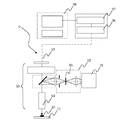
静電潜像現像用キャリアの断面図を図1(a)に示し、該キャリアの光透過性の樹脂コート膜厚測定の原理を、キャリア10の構成として、図1(b)の如き場合を例として説明する。即ち、この場合、光透過性の樹脂コート膜は微細粒子3と樹脂コート膜2により構成される。
光透過性の樹脂コート膜2のバインダー樹脂屈折率は、1.4〜1.8程であり、従って、微細粒子3の屈折率が1.77程の場合は、微細粒子とバインダー樹脂との相対屈折率(=微細粒子屈折率/バインダー樹脂屈折率)が1.0〜1.3の範囲となれば、膜厚測定に当たってバインダー樹脂と微細粒子3の界面反射は殆ど無視して考えることができる。
A cross-sectional view of the carrier for developing an electrostatic latent image is shown in FIG. 1A, and the principle of measuring the thickness of the light-transmitting resin coat of the carrier is the structure of the
The refractive index of the binder resin of the light-transmitting resin coat film 2 is about 1.4 to 1.8. Therefore, when the refractive index of the
集光された光は、一部が、キャリアの表面、即ち光透過性の樹脂コート膜2の表面で反射され、一部は、光透過性の樹脂コート膜2内に入射し、磁性微粉体1の表面で反射される。これら反射光は図2に示す対物レンズ94及び顕微鏡光学系93を介して「検出光伝送用ファイバ95の端面」に集光され、同ファイバ95により分光手段96へ「検出光」として伝送される。伝送された検出光は分光手段96により分光され、その分光スペクトル強度がスペクトル強度検出手段97により検出される。9は膜厚計測システム、91は光源、99はケーラー照明系の開口絞りである。
Part of the collected light is reflected by the surface of the carrier, that is, the surface of the light-transmitting resin coat film 2, and part of the light is incident on the light-transmitting resin coat film 2, and the magnetic fine powder 1 is reflected by the surface. These reflected lights are condensed on the “end face of the detection light transmission fiber 95” via the
図3は、上記のようにしてスペクトル強度検出手段97により検出されたデータ(検出値)と、演算手段98において非線形最小2乗法(例えば、シンプレックス法等のカーブフィットアルゴリズム)により「連続した分光スペクトル強度」として演算されたもの(演算値)である。図3に示すように、分光スペクトル強度は、可視域を含む、波長:450nmから波長800nmの300nm以上の領域にわたって有限であり、全波長領域で強度が波長とともに振動的に変化する。 FIG. 3 shows the “continuous spectral spectrum” obtained by the data (detected value) detected by the spectrum intensity detecting means 97 as described above and the non-linear least square method (for example, curve fitting algorithm such as simplex method) in the calculating means 98. It is calculated as “intensity” (calculated value). As shown in FIG. 3, the spectral spectrum intensity is finite over a range of wavelengths from 450 nm to 300 nm including the visible range, including the visible range, and the intensity changes in a vibrational manner with the wavelength in the entire wavelength range.
分光スペクトル強度のこのような振動的な変化は「検出光における干渉」の結果であるが、分光スペクトル強度の振動的な変化の振幅は、波長:450nmより短波長側と780nmより長波長側ではノイズが急激に重畳してくる。これは、顕微鏡光学系と対物レンズの透過率が急激に低下する事に起因しており、この場合、透過波長領域が狭いと、膜厚計測に必要な分光スペクトル強度の極小と極大を与える各波長の検出が出来なくなり、膜厚計測の精度が著しく低下する。
また、測定波長が「光透過性の樹脂コート膜に含まれた微細粒子の粒径よりもある程度大きく」なると、光は微細粒子に散乱されなくなり、検出光において良好に干渉する。
Such a vibrational change in the spectral spectrum intensity is a result of “interference in the detection light”, but the amplitude of the vibrational change in the spectral spectrum intensity is at a wavelength: shorter than 450 nm and longer than 780 nm. Noise suddenly superimposes. This is because the transmittance of the microscope optical system and the objective lens rapidly decreases. In this case, if the transmission wavelength region is narrow, each of the spectral spectrum intensity minimums and maximums necessary for film thickness measurement is given. Wavelength cannot be detected, and the accuracy of film thickness measurement is significantly reduced.
Further, when the measurement wavelength becomes “somewhat larger than the particle size of the fine particles contained in the light-transmitting resin coat film”, the light is not scattered by the fine particles and interferes favorably in the detection light.
波長:450nm〜800nmの波長領域において、演算値の分光スペクトル強度の変化において「隣接する極大と極小」の適当なものを選択し、これら極大・極小を与える波長を、λ2m、λ2m+1とする。mは「干渉の次数」であり適宜に定めることができる。
そうすると、光透過性の樹脂コート膜の厚さ:dと、光透過性の樹脂コート膜の屈折率:n1と、上記干渉の次数:mとの間には周知の如く、
2m=4n1d/λ2m
2m+1=4n1d/λ2m+1
の関係が成り立つので、これらから干渉次数:mを消去すると、
n1d=λ2m・λ2m+1/4(λ2m−λ2m+1)
が得られる。
従って、上記極大・極小を与える波長:λ2m、λ2m+1が分かると、光透過性の樹脂コート膜の光学的膜厚:n1dが知られ、さらに、屈折率:n1が分かれば、求める光透過性の樹脂コート膜の厚さ:dは、
d=λ2m・λ2m+1/4n1(λ2m−λ2m+1)(1)
として算出することができる。
Wavelength: In the wavelength region of 450 nm to 800 nm, an appropriate value of “adjacent maximum and minimum” is selected in the change of the spectral spectrum intensity of the calculated value, and the wavelengths giving these maximum and minimum are λ 2m and λ 2m + 1 . m is the “order of interference” and can be determined as appropriate.
Then, the thickness of the light transparent resin coating film: d the refractive index of the light transparent resin coating film: and n 1, the interference of order: As is well known between the m,
2m = 4n 1 d / λ 2m
2m + 1 = 4n 1 d / λ 2m + 1
Therefore, if the interference order: m is eliminated from these,
n 1 d = λ 2m · λ 2m + 1/4 (λ 2m −λ 2m + 1 )
Is obtained.
Accordingly, if the wavelengths λ 2m and λ 2m + 1 that give the maximum and minimum are known, the optical film thickness n 1 d of the light-transmitting resin coat film is known, and if the refractive index n 1 is known, Desired light-transmitting resin coat film thickness: d is
d = λ 2m · λ 2m + 1 / 4n 1 (λ 2m −λ 2m + 1 ) (1)
Can be calculated as
屈折率:n1は、光透過性の樹脂コート膜2の材質が定まれば一義的に定まるものであり、その分光特性、即ち、波長による屈折率の変化(分光屈折率)を予め制御手段98内にテーブルあるいは「波長の関数」として記憶しておくことができ、このようにして、分光スペクトル強度における極小と極大を与える各波長:λ2m+1、λ2mと、光透過性の樹脂コート膜2の屈折率:n1とに基づき光透過性の樹脂コート膜の膜厚:dを、上記(1)式に従って演算算出することができる。
一般に屈折率:n1は、バインダー樹脂の種類、微細粒子の含有率、微細粒子の屈折率が定まれば決定されるものであり、樹脂コート膜中にバインダー樹脂より高い屈折率を有する微細粒子がフィラーリッチ状態で存在する場合、樹脂コート膜の屈折率は微細粒子の光学的特性が支配的となり、樹脂コート膜自体の屈折率が微細粒子の影響を多く受ける形となる。
即ち、演算手段98は、スペクトル強度検出手段97により検出されたデータを「連続した分光スペクトル強度」として演算し、得られた分光スペクトル強度に対して微分演算等により、極小・極大を与える各波長:λ2m+1、λ2mを特定し、光透過性の樹脂コート膜2の屈折率:n1とに基づき光透過性の樹脂コート膜の膜厚:dを、上記の(1)式に従って演算算出する。
The refractive index: n 1 is uniquely determined if the material of the light-transmitting resin coat film 2 is determined, and its spectral characteristics, that is, the change in refractive index depending on the wavelength (spectral refractive index) is previously controlled. 98 can be stored as a table or as a “function of wavelength”, and thus each wavelength: λ 2m + 1 , λ 2m that gives the minimum and maximum in spectral spectrum intensity, and a light-transmitting resin-coated film Based on the refractive index of 2: n 1 , the film thickness: d of the light-transmitting resin coat film can be calculated according to the above equation (1).
In general, the refractive index n 1 is determined when the kind of binder resin, the content of fine particles, and the refractive index of fine particles are determined, and the fine particles having a higher refractive index than the binder resin in the resin coat film. Is present in a filler-rich state, the refractive index of the resin coat film is dominated by the optical characteristics of the fine particles, and the refractive index of the resin coat film itself is greatly affected by the fine particles.
That is, the calculation means 98 calculates the data detected by the spectrum intensity detection means 97 as “continuous spectral spectrum intensity”, and each wavelength that gives the minimum / maximum by differential calculation etc. with respect to the obtained spectral spectrum intensity. : Λ 2m + 1 and λ 2m are specified, and the film thickness: d of the light-transmitting resin coat film is calculated based on the refractive index: n 1 of the light-transmitting resin coat film 2 according to the above equation (1). To do.
この様に、所望波長領域のスペクトル光を放射する光源からの光を、ケーラー照明系92を備えた顕微鏡光学系93を介して対物レンズにより集光し、集光光束を上記光透過性の樹脂コート膜2に垂直入射させる。スペクトル光の「所望波長領域」は、光透過性の樹脂コート膜厚測定を可能ならしむる波長領域を意味し、光透過性樹脂コート膜2の構成(微細粒子の粒径、凝集径等)により定められる。
この場合、集束光のフォーカス位置を樹脂コート膜表面から磁性微粉体側に寄せた状態で、上記光透過性の樹脂コート膜表面と磁性微粉体表面とにより反射して互いに干渉した反射光を、上記対物レンズ94を介して顕微鏡光学系93に戻し、検出光伝送用ファイバ95により分光手段96に導いて可視域を含む300nm以上の波長幅で分光する。分光により得られる分光スペクトル強度の極小と極大を与える各波長と、上記樹脂コート膜2の屈折率とに基づき、光透過性の樹脂コート膜の膜厚を演算算出する。
即ち、本発明の静電潜像現像用キャリアの樹脂コート膜厚計測には、周知の「分光反射率測定法」の原理を利用できる。
In this way, light from a light source that emits spectrum light in a desired wavelength region is condensed by the objective lens via the microscope optical system 93 provided with the
In this case, the reflected light reflected by the light-transmitting resin coat film surface and the magnetic fine powder surface and interfering with each other in the state where the focus position of the focused light is shifted from the resin coat film surface to the magnetic fine powder side, The light is returned to the microscope optical system 93 via the
That is, the principle of the well-known “spectral reflectance measurement method” can be used to measure the resin coat film thickness of the carrier for developing an electrostatic latent image of the present invention.
以上、説明したように、膜厚(光透過性の樹脂コート膜2の厚み)の演算算出には「光透過性の樹脂コート膜の複素屈折率のデータ」が必要であり、上記に説明した例では、光透過性の樹脂コート膜の複素屈折率が、制御手段98に利用可能に記憶されている。静電潜像現像用キャリアは、画像形成装置の機種毎に種々のものが用いられており、それらキャリアにおける光透過性の樹脂コート膜の材質も多岐にわたっている。 As described above, calculation of the film thickness (thickness of the light-transmitting resin coat film 2) requires “data of complex refractive index of the light-transmitting resin coat film”, which has been described above. In the example, the complex refractive index of the light-transmitting resin coat film is stored in the control means 98 so as to be usable. Various electrostatic latent image developing carriers are used for each model of the image forming apparatus, and there are a wide variety of materials for the light-transmitting resin coat film in these carriers.
本発明のキャリアの構成は、前記特定の範囲のものである限り、それを構成する材料は限定するものではなく、従来公知のものが使用でき、例えば、真球状の磁性微粉体としては、マグネタイト、γ−酸化鉄、フェライト鉄、過剰型フェライトの如き酸化鉄;鉄、コバルト、ニッケルの如き磁性金属;酸化鉄又は磁性金属と、コバルト、スズ、チタン、銅、鉛、亜鉛、マグネシウム、マンガン、アルミニウム、珪素の如き金属との複合金属酸化物合金、又は混合物が挙げられる。これら磁性粒子は、平均粒径が30〜100μmの範囲内であることが好ましく、より好ましくは30〜60μmの範囲内であることが良い。
磁性粒子の形状としては、8面体、6面体、球形、針状、鱗片状があるが、真球形の異方性の少ないものが好ましい。
As long as the structure of the carrier of the present invention is within the above specific range, the material constituting the carrier is not limited, and conventionally known materials can be used. For example, as a spherical magnetic fine powder, magnetite , Γ-iron oxide, ferritic iron, iron oxide such as excess ferrite; magnetic metal such as iron, cobalt, nickel; iron oxide or magnetic metal and cobalt, tin, titanium, copper, lead, zinc, magnesium, manganese, Examples thereof include a composite metal oxide alloy with a metal such as aluminum or silicon, or a mixture thereof. These magnetic particles preferably have an average particle size in the range of 30 to 100 μm, more preferably in the range of 30 to 60 μm.
The shape of the magnetic particles includes octahedron, hexahedron, spherical shape, needle shape, and scale shape, but a true spherical shape with little anisotropy is preferable.
次に、樹脂コート膜を形成するバインダー樹脂としては、例えばポリエチレン、ポリプロピレン、塩素化ポリエチレン、クロロスルホン化ポリエチレン等のポリオレフィン系樹脂;ポリスチレン、アクリル系樹脂(例えばポリメチルメタクリレート)、ポリアクリロニトリル、ポリビニルアセテート、ポリビニルアルコール、ポリビニルブチラール、ポリ塩化ビニル、ポリビニルカルバゾール、ポリビニルエーテル、ポリビニルケトン等のポリビニル及びポリビニリデン系樹脂;塩化ビニル−酢酸ビニル共重合体;オルガノシロキサン結合からなるシリコーン樹脂またはその変性品(例えばアルキッド樹脂、ポリエステル樹脂、エポキシ樹脂、ポリウレタン等による変性品);ペルヒドロポリシラザンまたはその変性品(部分酸化品を含む);ポリテトラフルオロエチレン、ポリ弗化ビニル、ポリ弗化ビニリデン、ポリクロロトリフルオロエチレン等の弗素樹脂;ポリアミド;ポリエステル;ポリウレタン;ポリカーボネート;ユリア樹脂;メラミン樹脂;ベンゾグアナミン樹脂;エポキシ樹脂等が挙げられる。中でも本発明の構成要件を満たすために好ましいコート層材料としては、シリコーン樹脂またはその変性品、ペルヒドロポリシラザンまたはその変性品、弗素樹脂、特にシリコーン樹脂またはその変性品等の主鎖および/または側鎖にシロキサン結合骨格を有する化合物がより好ましい。 Next, examples of the binder resin for forming the resin coat film include polyolefin resins such as polyethylene, polypropylene, chlorinated polyethylene, and chlorosulfonated polyethylene; polystyrene, acrylic resins (for example, polymethyl methacrylate), polyacrylonitrile, and polyvinyl acetate. , Polyvinyl alcohol, polyvinyl butyral, polyvinyl chloride, polyvinyl carbazole, polyvinyl ether, polyvinyl ketone, and other polyvinyl and polyvinylidene resins; vinyl chloride-vinyl acetate copolymers; silicone resins composed of organosiloxane bonds or modified products thereof Modified products with alkyd resin, polyester resin, epoxy resin, polyurethane, etc.); Perhydropolysilazane or modified products thereof (including partially oxidized products) Polytetrafluoroethylene, polyvinyl fluoride, polyvinylidene fluoride, fluorine resin such as polychlorotrifluoroethylene; polyamides; polyesters; polyurethanes; polycarbonates; urea resins; melamine resins; benzoguanamine resins, epoxy resins and the like. Among them, preferred coating layer materials for satisfying the constituent requirements of the present invention include silicone resins or modified products thereof, perhydropolysilazane or modified products thereof, fluorine resins, particularly silicone resins or modified products thereof, and the main chain and / or sides. A compound having a siloxane bond skeleton in the chain is more preferred.
シリコーン樹脂としては、従来から知られているいずれのシリコーン樹脂であってもよく、下記一般式で示されるオルガノシロキサン結合のみからなるストレートシリコーンおよびアルキド、ポリエステル、エポキシ、ウレタンなどで変性したシリコーン樹脂が挙げられる。

また樹脂コート膜の電気抵抗を電気抵抗制御材料の分散により制御することが好ましい。その際に用いられる材料は、従来公知の物で良く、その例としては、鉄、金、銅等の金属;フェライト、マグネタイト等の酸化鉄;カーボンブラック等の顔料が挙げられる。この中でも特にカーボンブラックを用いることにより、少量の低抵抗微粉末の添加で効果的に導電性の調整が可能であり、好ましく用いられる。 Moreover, it is preferable to control the electric resistance of the resin coating film by dispersing the electric resistance control material. The material used in that case may be a conventionally known material, and examples thereof include metals such as iron, gold, and copper; iron oxides such as ferrite and magnetite; and pigments such as carbon black. Among these, the use of carbon black is particularly preferred because it can effectively adjust the conductivity with the addition of a small amount of low resistance fine powder.
光透過性の樹脂コート膜に外添する電気抵抗制御材料粒子の平均一次粒子径は、測定光に散乱・回折の影響を与えない20〜200nmであることが好ましく、また、キャリア樹脂コート膜に対する電気抵抗制御材料粒子の割合は、0.01〜2重量%であることが好ましい。電気抵抗制御材料粒子の一次粒子径が、200nmを上回る様な場合には、測定光の回折の影響が生じやすく、特にサブストレイトである真球状の磁性微粉体からの反射光が低減し、干渉波形が現れない場合がある。 The average primary particle diameter of the electrical resistance control material particles externally added to the light-transmitting resin coat film is preferably 20 to 200 nm which does not affect the measurement light by scattering and diffraction. The proportion of the electric resistance control material particles is preferably 0.01 to 2% by weight. When the primary particle diameter of the electric resistance control material particles exceeds 200 nm, the influence of the diffraction of the measurement light is likely to occur, and particularly the reflected light from the true spherical magnetic fine powder as a substrate is reduced and interference occurs. The waveform may not appear.
さらに、樹脂コート膜中には、これらの密着性を向上させたり電気抵抗制御材の分散性を向上させる目的でシランカップリング剤、チタンカップリング剤等のカップリング剤を助剤として添加しても良い。本発明で用いられるシランカップリング剤の例としては、下記一般式で示される化合物が挙げられる。
![]()
![]()
このシランカップリング剤の中でも、特に負帯電性を有する現像剤を得るにはYにアミノ基を有するアミノシランカップリング剤が好ましく、正帯電性を有する現像剤を得るにはYにエポキシ基を有するエポキシシランカップリング剤が好ましい。 Among these silane coupling agents, an aminosilane coupling agent having an amino group in Y is preferable for obtaining a negatively charged developer, and Y has an epoxy group in order to obtain a positively charged developer. Epoxy silane coupling agents are preferred.
樹脂コート層の形成法としては、コア材粒子の表面にコート層形成液を、樹脂コート層を平滑に塗布可能な浸漬法で塗布すればよい。
例えば、前記したコート樹脂の内、熱硬化性を有する成分(熱硬化性成分)と熱可塑性を有する成分(熱可塑性成分)を特定の割合で混合またはブロック重合し、これを、浸漬コート法によって、均一に塗工後、熱硬化性成分の硬化温度以上、熱可塑性成分の軟化温度以上にかつ分解温度以下の温度範囲で焼成して、コート層成分の硬化および平滑化を同時に行うことにより、樹脂コート層表面の凹凸の周期と振幅を各々0.1μm以下にすることができる。コート層の厚さは0.1〜20μmが好ましい。
As a method for forming the resin coat layer, a coat layer forming liquid may be applied to the surface of the core material particles by an immersion method that can apply the resin coat layer smoothly.
For example, among the coating resins described above, a thermosetting component (thermosetting component) and a thermoplastic component (thermoplastic component) are mixed or block polymerized at a specific ratio, and this is performed by a dip coating method. After uniformly coating, by baking at a temperature range above the curing temperature of the thermosetting component, above the softening temperature of the thermoplastic component and below the decomposition temperature, and simultaneously curing and smoothing the coating layer component, The period and amplitude of the unevenness on the surface of the resin coat layer can be set to 0.1 μm or less, respectively. The thickness of the coat layer is preferably from 0.1 to 20 μm.
さらに、前記したように光透過性の樹脂コート膜の表面の周期と振幅が各々0.1μm以下であることが好ましく、これ以上の場合には、前述した様に測定光が回折・散乱されて、分光反射率測定法で光透過性の樹脂コート膜厚を計測が出来ない事態が生じる場合がある。このような真球状の磁性微粉体上に、微細粒子を分散させた光透過性の樹脂コート層を設けた静電潜像現像用キャリア粒子は、前記した樹脂コート樹脂中の微細粒子成分を適正量に保ち、かつ、充分な分散を行わせることにより得られ、具体的には光透過性の樹脂コート膜組成中の微細粒子の成分が85重量%以下であることが好ましく、かつ、樹脂コート層内での分散状態が均一であることにより得られる。 Furthermore, as described above, it is preferable that the period and amplitude of the surface of the light-transmitting resin coat film are each 0.1 μm or less, and in this case, the measurement light is diffracted and scattered as described above. In some cases, the film thickness of the light-transmitting resin coat cannot be measured by the spectral reflectance measurement method. Carrier particles for electrostatic latent image development in which a light-transmitting resin-coated layer in which fine particles are dispersed on such a spherical magnetic fine powder are suitable for the fine particle component in the resin-coated resin described above. The amount of fine particles in the light-transmitting resin coat film composition is preferably 85% by weight or less, and is obtained by maintaining the amount and carrying out sufficient dispersion. It is obtained when the dispersion state in the layer is uniform.
以下、実施例により本発明を具体的に詳細に説明するが、本発明は以下の実施例に限定されるものではない。また、ここで「部」、「%」は全て重量部、重量%を示す。 EXAMPLES Hereinafter, although an Example demonstrates this invention concretely in detail, this invention is not limited to a following example. Here, “parts” and “%” all represent parts by weight and% by weight.
分光反射率法により膜厚計測可能なキャリアは次の様に作製した。
実施例1(キャリア1)
真球状の磁性微粉体としては、表面の凹凸の周期と振幅が各々0.1μm以下であり、磁性微粉体と光透過性の樹脂コート膜との相対屈折率(=磁性微粉体屈折率/樹脂コート膜屈折率)が1.5〜2.1の範囲に収まるように屈折率:2.42、消光係数:3.3のマグネタイト粒子を用いた。磁性微粉体表面の凹凸の周期と振幅はWyko NT3300 Optical Profilerで得られたX及びY−Profileで計測した。各々、0.1μm以下であった。
バインダー樹脂として、屈折率:1.4のシリコーン樹脂(SR2411:東レダウコーニングシリコーン社製)の固形分に対して、屈折率:1.78、消光係数:0のアルミナ微細粒子(住友化学工業製 スミコランダムAA−03、0.3μm、軸比1.1、バンドギャップエネルギー6.9eV、凝集径0.6μm)の20重量%を、ホモジナイザーを使用して30分間分散し、この分散液を固形分10重量%になるように希釈し、樹脂コート膜用分散液を得た。
上記磁性微粉体5kgに対して、上記の分散液を流動床型コーティング装置を用いて、100℃の雰囲気下で、約50g/minの割合で塗布した。更に、300℃で2時間加熱して、樹脂コート膜を乾燥硬化させたキャリアを得た。
A carrier capable of measuring the film thickness by the spectral reflectance method was prepared as follows.
Example 1 (carrier 1)
As the spherical magnetic fine powder, the period and amplitude of the surface irregularities are each 0.1 μm or less, and the relative refractive index between the magnetic fine powder and the light-transmitting resin coat film (= magnetic fine powder refractive index / resin Magnetite particles having a refractive index of 2.42 and an extinction coefficient of 3.3 were used so that the coating film refractive index was in the range of 1.5 to 2.1. The period and amplitude of the irregularities on the surface of the magnetic fine powder were measured by X and Y-Profile obtained with Wyko NT3300 Optical Profiler. Each was 0.1 μm or less.
As binder resin, alumina fine particles (manufactured by Sumitomo Chemical Co., Ltd.) having a refractive index of 1.78 and an extinction coefficient of 0 with respect to the solid content of a silicone resin having a refractive index of 1.4 (SR2411 manufactured by Toray Dow Corning Silicone). 20% by weight of Sumicorundum AA-03, 0.3 μm, axial ratio 1.1, band gap energy 6.9 eV, aggregate diameter 0.6 μm) was dispersed for 30 minutes using a homogenizer, and this dispersion was solidified. The mixture was diluted to 10% by weight to obtain a dispersion for a resin coat film.
The dispersion was applied to 5 kg of the magnetic fine powder at a rate of about 50 g / min in an atmosphere at 100 ° C. using a fluidized bed type coating apparatus. Furthermore, it heated at 300 degreeC for 2 hours, and the carrier which dried and hardened the resin coat film | membrane was obtained.
この際、微細粒子と光透過性のバインダー樹脂との相対屈折率(=微細粒子屈折率/バインダー樹脂屈折率)を1.3とした。また、磁性微粉体であるマグネタイトと光透過性の樹脂コート膜との相対屈折率(=磁性微粉体屈折率/樹脂コート膜屈折率)は、1.51であった。更に、樹脂コート膜と空気との相対屈折率(=樹脂コート膜屈折率/空気屈折率)は1.6であった。
形成された樹脂コート層表面をWyko NT3300 Optical Profilerで計測したところ凹凸の周期と振幅が各々0.08μmであった。
At this time, the relative refractive index (= fine particle refractive index / binder resin refractive index) between the fine particles and the light-transmitting binder resin was set to 1.3. Further, the relative refractive index (= magnetic fine powder refractive index / resin coat film refractive index) between the magnetic fine magnetite and the light-transmitting resin coat film was 1.51. Furthermore, the relative refractive index between the resin coat film and air (= resin coat film refractive index / air refractive index) was 1.6.
When the surface of the formed resin coat layer was measured with Wyko NT3300 Optical Profiler, the period and amplitude of the unevenness were 0.08 μm, respectively.
上記実施例1で得られた静電潜像現像用キャリアについて、オリンパス光学工業(株)製顕微鏡BX60の改造機と分光器を用い、真球状の磁性微粉体表面と光透過性の樹脂コート膜表面との繰り返し反射に起因する干渉波形の抽出を試み、光透過性の樹脂コート膜と磁性微粉体の光の分散値(複素屈折率データ)を用いることにより光透過性の樹脂コート膜厚の計測を試みた。測定サンプルである静電潜像現像用キャリア粒子は、スライドガラス平板上へ薄く散布した。
その結果、測定領域内にある各サンプルについて頂点部分を測定して、10点膜厚計測値を算出し、平均膜厚:0.49μm、分解能:0.005μm以下、同一箇所繰り返し精度(バラツキ)σ=0.0008μmの計測結果が得られた。
For the electrostatic latent image developing carrier obtained in Example 1 above, using a remodeling machine and a spectroscope of the microscope BX60 manufactured by Olympus Optical Co., Ltd., a spherical magnetic fine powder surface and a light-transmitting resin-coated film Attempts to extract the interference waveform caused by repeated reflection from the surface, and by using the light dispersion value (complex refractive index data) of the light-transmissive resin coat film and magnetic fine powder, I tried to measure. Carrier particles for developing an electrostatic latent image as a measurement sample were thinly dispersed on a glass slide plate.
As a result, the vertex portion is measured for each sample in the measurement region, and a 10-point film thickness measurement value is calculated. Average film thickness: 0.49 μm, resolution: 0.005 μm or less, repeatability at the same location (variation) A measurement result of σ = 0.0008 μm was obtained.
実施例2(キャリア2)
実施例1(キャリア1の製造例)において、真球状のキャリア芯材として、屈折率:2.94、消光係数:3.9のヘマタイト粒子(表面の凹凸の周期:0.08μm、振幅:0.08μm)を用いて磁性微粉体と光透過性の樹脂コート膜との相対屈折率(=磁性微粉体屈折率/樹脂コート膜屈折率)を1.84とした以外は、すべて実施例1と同様にしてキャリア2を得た。
Example 2 (Carrier 2)
In Example 1 (manufacturing example of carrier 1), hematite particles having a refractive index of 2.94 and an extinction coefficient of 3.9 (surface irregularity period: 0.08 μm, amplitude: 0) are used as a true spherical carrier core material. 0.08 μm), and the relative refractive index (= magnetic fine powder refractive index / resin coated film refractive index) between the magnetic fine powder and the light-transmitting resin-coated film was 1.84. Carrier 2 was obtained in the same manner.
上記実施例2で得られた静電潜像現像用キャリアについて、同様にオリンパス光学工業(株)製顕微鏡BX60の改造機と分光器を用い、真球状の磁性微粉体表面と光透過性の樹脂コート膜表面との繰り返し反射に起因する干渉波形の抽出を試み、光透過性の樹脂コート膜と磁性微粉体の光の分散値(複素屈折率データ)を用いることにより光透過性の樹脂コート膜厚の計測を試みた。測定サンプルである静電潜像現像用キャリア粒子は、スライドガラス平板上へ薄く散布した。
その結果、界面反射が弱い磁性微粉体表面の反射を多く稼ぐことが可能となり、より可視度の高い干渉スペクトルを得る事ができた。
測定領域内にある各サンプルについて頂点部分を測定して、10点膜厚計測値を算出し、平均膜厚:0.38μm、分解能:0.005μm以下、同一箇所繰り返しバラツキσ=0.0003μmの計測結果が得られた。
For the electrostatic latent image developing carrier obtained in Example 2 above, the surface of a spherical magnetic fine powder and a light-transmitting resin were similarly used using a remodeling machine and a spectroscope of a microscope BX60 manufactured by Olympus Optical Co., Ltd. Attempts to extract the interference waveform caused by repeated reflections on the surface of the coating film, and the light-transmitting resin-coated film by using the light-transmitting resin-coated film and the light dispersion value (complex refractive index data) of the magnetic fine powder Attempted to measure thickness. Carrier particles for developing an electrostatic latent image as a measurement sample were thinly dispersed on a glass slide plate.
As a result, it was possible to earn a lot of reflection on the surface of the magnetic fine powder having weak interface reflection, and an interference spectrum with higher visibility could be obtained.
The vertex portion is measured for each sample in the measurement region, and the 10-point film thickness measurement value is calculated. The average film thickness is 0.38 μm, the resolution is 0.005 μm or less, and the same part repeat variation σ = 0.0003 μm. Measurement results were obtained.
実施例3(キャリア3)
実施例1(キャリア1の製造例)において、バインダー樹脂として屈折率:1.48のアクリル樹脂溶液(日立化成社製 ヒタロイド3019)の固形分に対して、屈折率:1.78、消光係数:0のアルミナ微細粒子(住友化学工業製 スミコランダムAA−03 0.3μm 軸比1.1)の30重量%を、ホモジナイザーを使用して30分間分散し、この分散液を固形分5重量%になるように希釈し、樹脂コート膜用分散液を得た以外は、すべて同様にしてキャリア3を得た。微細粒子とバインダー樹脂との相対屈折率(=微細粒子屈折率/バインダー樹脂屈折率)は1.2となった。また樹脂コート膜の屈折率は1.61であった。
Example 3 (Carrier 3)
In Example 1 (production example of carrier 1), the refractive index is 1.78, the extinction coefficient is based on the solid content of an acrylic resin solution (Hitaloid 3019, manufactured by Hitachi Chemical Co., Ltd.) having a refractive index of 1.48 as a binder resin. 30% by weight of 0 alumina fine particles (Sumitomo Chemical Co., Ltd. Sumiko Random AA-03 0.3 μm axial ratio 1.1) was dispersed for 30 minutes using a homogenizer, and this dispersion was made to have a solid content of 5% by weight. The
上記実施例3で得られた静電潜像現像用キャリアについて、同様にオリンパス光学工業(株)製顕微鏡BX60の改造機と分光器を用い、真球状の磁性微粉体表面と光透過性の樹脂コート膜表面との繰り返し反射に起因する干渉波形の抽出を試み、光透過性の樹脂コート膜と磁性微粉体の光の分散値(複素屈折率データ)を用いることにより光透過性の樹脂コート膜厚の計測を試みた。測定サンプルである静電潜像現像用キャリア粒子は、スライドガラス平板上へ薄く散布した。
その結果、測定領域内にある各サンプルについて頂点部分を測定して、10点膜厚計測値を算出し、平均膜厚:0.27μm、分解能:0.005μm以下、同一箇所繰り返し精度(バラツキ)σ=0.0009μmの計測結果が容易に得られた。
For the electrostatic latent image developing carrier obtained in Example 3 above, the surface of a spherical magnetic fine powder and a light-transmitting resin were similarly used using a remodeling machine and a spectroscope of the microscope BX60 manufactured by Olympus Optical Co., Ltd. Attempts to extract the interference waveform caused by repeated reflections on the surface of the coating film, and the light-transmitting resin-coated film by using the light-transmitting resin-coated film and the light dispersion value (complex refractive index data) of the magnetic fine powder Attempted to measure thickness. Carrier particles for developing an electrostatic latent image as a measurement sample were thinly dispersed on a glass slide plate.
As a result, the vertex portion is measured for each sample in the measurement region, and a 10-point film thickness measurement value is calculated. Average film thickness: 0.27 μm, resolution: 0.005 μm or less, repeatability at the same location (variation) A measurement result of σ = 0.0009 μm was easily obtained.
比較例1(キャリア4)
実施例1(キャリア1の製造例)において、表面の凹凸の周期と振幅が各々0.1μm以下であり、屈折率:2.98、消光係数4.0のフェライト粒子を用い、バインダー樹脂として、屈折率:1.4のシリコーン樹脂(SR2411:東レダウコーニングシリコーン社製)の固形分に対して、屈折率:1.78、消光係数:0のアルミナ微細粒子(住友化学工業製 スミコランダムAA−03 0.3μm 軸比1.1)の含有率を88重量%とした以外は、すべて同様にしてキャリア4を得た。この際、樹脂コート膜の屈折率は、1.98であった。
Comparative Example 1 (Carrier 4)
In Example 1 (manufacturing example of carrier 1), the period and amplitude of the surface irregularities are each 0.1 μm or less, and ferrite particles having a refractive index of 2.98 and an extinction coefficient of 4.0 are used as a binder resin. Refractive index: 1.4 fine particles of alumina (SR 2411: manufactured by Toray Dow Corning Silicone Co., Ltd.), fine particles of alumina having a refractive index of 1.78 and an extinction coefficient of 0 (Sumiko Random AA- The carrier 4 was obtained in the same manner except that the content of 03 0.3 μm axial ratio 1.1) was 88% by weight. At this time, the refractive index of the resin coat film was 1.98.
上記比較例1で得られた静電潜像現像用キャリアについて、同様にオリンパス光学工業(株)製 顕微鏡BX60の改造機と分光器を用い、真球状の磁性微粉体表面と光透過性の樹脂コート膜表面との繰り返し反射に起因する干渉波形の抽出を試み、光透過性の樹脂コート膜と磁性微粉体の光の分散値(複素屈折率データ)を用いることにより光透過性の樹脂コート膜厚の計測を試みた。測定サンプルである静電潜像現像用キャリア粒子は、スライドガラス平板上へ薄く散布した。
ここで、キャリア粒子表面コート層の膜厚測定は、樹脂コート膜と空気との相対屈折率(=樹脂コート膜屈折率/空気屈折率)が1.98と1.8以上になってしまい、樹脂コート膜での界面反射が強くなりずぎることにより光が樹脂コート膜内に透過し難くなる為、図4に示す様に膜厚計測に必要な干渉波形の可視度が得られなくなり、分光反射率法を用いて樹脂コート膜厚計測を行うことが出来なかった。
For the electrostatic latent image developing carrier obtained in Comparative Example 1, the surface of a true spherical magnetic fine powder and a light-transmitting resin were similarly used using a modified machine and a spectroscope of the microscope BX60 manufactured by Olympus Optical Co., Ltd. Attempts to extract the interference waveform caused by repeated reflections on the surface of the coating film, and the light-transmitting resin-coated film by using the light-transmitting resin-coated film and the light dispersion value (complex refractive index data) of the magnetic fine powder Attempted to measure thickness. Carrier particles for developing an electrostatic latent image as a measurement sample were thinly dispersed on a glass slide plate.
Here, the measurement of the film thickness of the carrier particle surface coat layer is such that the relative refractive index between the resin coat film and air (= resin coat film refractive index / air refractive index) is 1.98 and 1.8 or more, Since the interface reflection at the resin coat film becomes too strong, it becomes difficult for light to pass through the resin coat film, so that the visibility of the interference waveform necessary for film thickness measurement cannot be obtained as shown in FIG. The resin coat film thickness could not be measured using the reflectance method.
(図1)
1 磁性微粉体
2 樹脂コート膜
3 微細粒子
10 キャリア
(図2)
9 膜厚計測システム
10 キャリア
11 スライドガラス
91 光源
92 ケーラー照明系
93 顕微鏡光学系
94 対物レンズ
95 検出光伝送用ファイバ
96 分光手段
97 スペクトル強度検出手段
98 演算システム
99 ケーラー照明系の開口絞り
(Figure 1)
DESCRIPTION OF SYMBOLS 1 Magnetic fine powder 2
DESCRIPTION OF SYMBOLS 9
Claims (9)
Priority Applications (1)
| Application Number | Priority Date | Filing Date | Title |
|---|---|---|---|
| JP2003289848A JP4339044B2 (en) | 2003-03-14 | 2003-08-08 | Electrostatic latent image development carrier |
Applications Claiming Priority (2)
| Application Number | Priority Date | Filing Date | Title |
|---|---|---|---|
| JP2003070748 | 2003-03-14 | ||
| JP2003289848A JP4339044B2 (en) | 2003-03-14 | 2003-08-08 | Electrostatic latent image development carrier |
Publications (2)
| Publication Number | Publication Date |
|---|---|
| JP2004302406A JP2004302406A (en) | 2004-10-28 |
| JP4339044B2 true JP4339044B2 (en) | 2009-10-07 |
Family
ID=33421706
Family Applications (1)
| Application Number | Title | Priority Date | Filing Date |
|---|---|---|---|
| JP2003289848A Expired - Fee Related JP4339044B2 (en) | 2003-03-14 | 2003-08-08 | Electrostatic latent image development carrier |
Country Status (1)
| Country | Link |
|---|---|
| JP (1) | JP4339044B2 (en) |
Families Citing this family (2)
| Publication number | Priority date | Publication date | Assignee | Title |
|---|---|---|---|---|
| JP4882067B2 (en) * | 2006-08-24 | 2012-02-22 | 国立大学法人東京農工大学 | Absolute reflectance measuring method and measuring apparatus |
| JP2008102394A (en) * | 2006-10-20 | 2008-05-01 | Ricoh Co Ltd | Carrier, replenishment developer, developer in developer, developer replenisher, image forming apparatus, process cartridge |
Family Cites Families (13)
| Publication number | Priority date | Publication date | Assignee | Title |
|---|---|---|---|---|
| JPS53125865A (en) * | 1977-04-11 | 1978-11-02 | Fujitsu Ltd | Inspection of alumite substrate |
| JP3521316B2 (en) * | 1994-03-31 | 2004-04-19 | 株式会社日立製作所 | Ultrafine particle film and method for forming the same |
| JPH0694923A (en) * | 1991-07-25 | 1994-04-08 | Ono Gijutsu Kenkyusho:Kk | Thin-walled light box |
| JPH05109819A (en) * | 1991-10-16 | 1993-04-30 | Matsushita Electric Ind Co Ltd | Manufacture of semiconductor device |
| JP3233750B2 (en) * | 1993-09-20 | 2001-11-26 | キヤノン株式会社 | Electrophotographic photoreceptor and electrophotographic apparatus |
| JP3646473B2 (en) * | 1997-05-20 | 2005-05-11 | 富士ゼロックス株式会社 | Multicolor image forming method |
| JPH11296926A (en) * | 1998-04-03 | 1999-10-29 | Sony Corp | Magneto-optical recording medium recording apparatus and its recording method, and magneto-optical recording medium reproducing apparatus and its reproducing method |
| JP3534632B2 (en) * | 1998-12-22 | 2004-06-07 | シャープ株式会社 | Film thickness measurement method |
| JP4245818B2 (en) * | 2001-03-05 | 2009-04-02 | 株式会社リコー | Inorganic optoelectronic material and electrophotographic photoreceptor using the same |
| JP2002270861A (en) * | 2001-03-08 | 2002-09-20 | Ricoh Co Ltd | Optical functional film and optical functional device using the same |
| JP4188570B2 (en) * | 2001-03-23 | 2008-11-26 | 株式会社リコー | Electrophotographic developer, image forming method and image forming apparatus |
| JP4121252B2 (en) * | 2001-03-27 | 2008-07-23 | 株式会社リコー | Electrostatic latent image developing carrier, developer, developing method and developing apparatus using the same |
| JP2002287432A (en) * | 2001-03-28 | 2002-10-03 | Ricoh Co Ltd | Electrostatic latent image developing method and developing apparatus |
-
2003
- 2003-08-08 JP JP2003289848A patent/JP4339044B2/en not_active Expired - Fee Related
Also Published As
| Publication number | Publication date |
|---|---|
| JP2004302406A (en) | 2004-10-28 |
Similar Documents
| Publication | Publication Date | Title |
|---|---|---|
| Wilson et al. | Size-dependent angular distributions of low-energy photoelectrons emitted from NaCl nanoparticles | |
| Vernon et al. | Influence of particle− substrate interaction on localized plasmon resonances | |
| Auguié et al. | Collective resonances in gold nanoparticle arrays | |
| Siegfried et al. | Engineering metal adhesion layers that do not deteriorate plasmon resonances | |
| Piechulla et al. | Fabrication of Nearly‐Hyperuniform Substrates by Tailored Disorder for Photonic Applications | |
| Borges et al. | Evolution of the surface plasmon resonance of Au: TiO2 nanocomposite thin films with annealing temperature | |
| Wang et al. | General method for determining light scattering and absorption of nanoparticle composites | |
| Saison-Francioso et al. | Plasmonic nanoparticles array for high-sensitivity sensing: a theoretical investigation | |
| Okamoto | Near-field spectral analysis of metallic beads | |
| Yeh et al. | Use of dispersion imaging for grating-coupled surface plasmon resonance sensing of multilayer Langmuir–Blodgett films | |
| JP4339044B2 (en) | Electrostatic latent image development carrier | |
| Yue et al. | Improved surface-enhanced Raman scattering on arrays of gold quasi-3D nanoholes | |
| Meyer et al. | Scanning angle plasmon waveguide resonance Raman spectroscopy for the analysis of thin polystyrene films | |
| Bleyer et al. | Predictive Design to Determine Optimal Absorber Placement in Colloidal Photonic Crystals | |
| Wormeester et al. | Effective dielectric response of nanostructured layers | |
| Rehman et al. | Determination of the optical thickness of sub 10-nm thin metal films by SPR experiments | |
| US9201320B2 (en) | Production process of organic photoreceptor | |
| Joerger et al. | Optical properties of inhomogeneous media | |
| US20060182948A1 (en) | Resin-coated metal sheet | |
| Fu et al. | High-sensitivity nanostructured aluminium ultrathin film sensors with spectral response from ultraviolet to near-infrared | |
| Brown et al. | Chemical interface damping for propagating surface plasmon polaritons in gold nanostripes | |
| Tesfamichael et al. | Optical characterization and modeling of black pigments used in thickness-sensitive solar-selective absorbing paints | |
| Bao et al. | Plasmon hybridization for real metals | |
| Bruzzone et al. | Light scattering by gold nanoparticles: Role of simple dielectric models | |
| Shurvinton et al. | Precise spectrophotometric method for semitransparent metallic thin-film index determination using interference enhancement |
Legal Events
| Date | Code | Title | Description |
|---|---|---|---|
| RD01 | Notification of change of attorney |
Free format text: JAPANESE INTERMEDIATE CODE: A7421 Effective date: 20050225 |
|
| A621 | Written request for application examination |
Free format text: JAPANESE INTERMEDIATE CODE: A621 Effective date: 20060201 |
|
| RD03 | Notification of appointment of power of attorney |
Free format text: JAPANESE INTERMEDIATE CODE: A7423 Effective date: 20060215 |
|
| A977 | Report on retrieval |
Free format text: JAPANESE INTERMEDIATE CODE: A971007 Effective date: 20080125 |
|
| A131 | Notification of reasons for refusal |
Free format text: JAPANESE INTERMEDIATE CODE: A131 Effective date: 20080212 |
|
| A521 | Written amendment |
Free format text: JAPANESE INTERMEDIATE CODE: A523 Effective date: 20080410 |
|
| A131 | Notification of reasons for refusal |
Free format text: JAPANESE INTERMEDIATE CODE: A131 Effective date: 20090120 |
|
| A521 | Written amendment |
Free format text: JAPANESE INTERMEDIATE CODE: A523 Effective date: 20090313 |
|
| TRDD | Decision of grant or rejection written | ||
| A01 | Written decision to grant a patent or to grant a registration (utility model) |
Free format text: JAPANESE INTERMEDIATE CODE: A01 Effective date: 20090630 |
|
| A01 | Written decision to grant a patent or to grant a registration (utility model) |
Free format text: JAPANESE INTERMEDIATE CODE: A01 |
|
| A61 | First payment of annual fees (during grant procedure) |
Free format text: JAPANESE INTERMEDIATE CODE: A61 Effective date: 20090701 |
|
| R150 | Certificate of patent or registration of utility model |
Free format text: JAPANESE INTERMEDIATE CODE: R150 |
|
| FPAY | Renewal fee payment (event date is renewal date of database) |
Free format text: PAYMENT UNTIL: 20120710 Year of fee payment: 3 |
|
| FPAY | Renewal fee payment (event date is renewal date of database) |
Free format text: PAYMENT UNTIL: 20120710 Year of fee payment: 3 |
|
| FPAY | Renewal fee payment (event date is renewal date of database) |
Free format text: PAYMENT UNTIL: 20130710 Year of fee payment: 4 |
|
| LAPS | Cancellation because of no payment of annual fees |