JP4337247B2 - Control device for internal combustion engine - Google Patents
Control device for internal combustion engine Download PDFInfo
- Publication number
- JP4337247B2 JP4337247B2 JP2000259113A JP2000259113A JP4337247B2 JP 4337247 B2 JP4337247 B2 JP 4337247B2 JP 2000259113 A JP2000259113 A JP 2000259113A JP 2000259113 A JP2000259113 A JP 2000259113A JP 4337247 B2 JP4337247 B2 JP 4337247B2
- Authority
- JP
- Japan
- Prior art keywords
- region
- engine
- combustion
- control valve
- state
- Prior art date
- Legal status (The legal status is an assumption and is not a legal conclusion. Google has not performed a legal analysis and makes no representation as to the accuracy of the status listed.)
- Expired - Fee Related
Links
Images


Classifications
-
- Y—GENERAL TAGGING OF NEW TECHNOLOGICAL DEVELOPMENTS; GENERAL TAGGING OF CROSS-SECTIONAL TECHNOLOGIES SPANNING OVER SEVERAL SECTIONS OF THE IPC; TECHNICAL SUBJECTS COVERED BY FORMER USPC CROSS-REFERENCE ART COLLECTIONS [XRACs] AND DIGESTS
- Y02—TECHNOLOGIES OR APPLICATIONS FOR MITIGATION OR ADAPTATION AGAINST CLIMATE CHANGE
- Y02T—CLIMATE CHANGE MITIGATION TECHNOLOGIES RELATED TO TRANSPORTATION
- Y02T10/00—Road transport of goods or passengers
- Y02T10/10—Internal combustion engine [ICE] based vehicles
- Y02T10/12—Improving ICE efficiencies
Landscapes
- Electrical Control Of Air Or Fuel Supplied To Internal-Combustion Engine (AREA)
- Combined Controls Of Internal Combustion Engines (AREA)
Description
【0001】
【発明の属する技術分野】
本発明は、内燃機関の制御装置に関するものである。
【0002】
【従来の技術】
近年、車載エンジン等の内燃機関においては、燃費改善等を意図して機関運転状態に応じて燃焼方式を成層燃焼と均質燃焼との間で切り換えるタイプのものが実用化されている。また、こうしたタイプの内燃機関では、例えば1999年9月24日発行の「クラウン、クラウンマジェスタ新型車解説書」に記載されるように、混合気の良好な燃焼が得られるよう燃焼室内のガスの流動状態を変更する気流制御弁を同機関の吸気通路に設けることも知られている。
【0003】
上記文献に示される内燃機関においては、機関運転状態が低回転低負荷領域(成層燃焼領域)にあるときには成層燃焼運転を実行し、それ以外の領域(均質燃焼領域)では均質燃焼運転を実行する。また、同機関の気流制御弁は、成層燃焼領域や均質燃焼領域における高回転高負荷側の領域では開弁され、均質燃焼領域における低回転高負荷側や高回転低負荷側の領域では閉弁されるようになる。なお、こうした気流制御弁の開閉制御は、
・成層燃焼運転時には燃焼室内でのガス流の助けをかりることなく点火プラグ周りに可燃混合気が形成される。
【0004】
・低回転高負荷時や高回転低負荷時には、気流制御弁を閉弁することにより、燃焼室内に乱流を生じさせて空気と燃料との混合を促進させること、及び燃焼室に吸入されるガスの流速を早めて吸気充填効率を向上させることが好ましい。
【0005】
・気流制御弁を閉弁するのが好ましいとき以外は同気流制御弁を開弁し、可能な限り気流制御弁の閉弁に伴う吸気抵抗の増大を抑制するのが好ましい。
等の理由に基づいてのものである。
【0006】
ところで、機関運転状態が成層燃焼領域と気流制御弁の閉弁される所定運転領域(均質燃焼領域における低回転高負荷側や高回転低負荷側)との間で移行する際には、燃焼方式が成層燃焼と均質燃焼との間で切り換えられるとともに、気流制御弁が開弁状態と閉弁状態との間で切り換えられる。
【0007】
燃焼方式が切り換えられる際には内燃機関の良好な運転を行う上で要求される燃料噴射量や点火時期等が変化し、これに応じて燃料噴射量や点火時期等を変化させる際にショックが生じ易くなる。また、気流制御弁が切り換えられる際にも内燃機関の良好な運転を行う上で要求される燃料噴射量や点火時期等が変化し、これに応じて燃料噴射量や点火時期等を変化させる際にショックが生じ易くなる。
【0008】
従って、燃焼方式の切り換えと気流制御弁の切り換えとが同時に行われると、要求される燃料噴射量や点火時期が上記のように燃焼方式に応じてだけでなく気流制御弁の開閉状態に応じても変化することから、それら燃料噴射量や点火時期等の制御態様によってはショックが生じるおそれがある。
【0009】
そこで、上記文献に記載の内燃機関では、燃焼方式の切り換えと気流制御弁の切り換えとが同時に生じないよう、気流制御弁が閉弁する上記所定運転領域を図9に破線で示すように均質燃焼領域内において成層燃焼領域から離して設定している。この場合、例えば機関運転状態が成層燃焼領域から上記所定運転領域に移行する際などには、最初に燃焼方式が成層燃焼から均質燃焼に切り換えられ、その後に気流制御弁が開弁状態から閉弁状態へと切り換えられるため、上記のようなショックの発生が抑制される。
【0010】
【発明が解決しようとする課題】
上記のように気流制御弁が閉弁される所定運転領域を設定することで、確かに上記ショックを抑制することができるようにはなる。ただし、上記所定運転領域を成層燃焼領域から離して設定するためには、同所定運転領域を狭くしなければならなくなる。
【0011】
即ち、上記所定運転領域のうち、均質燃焼領域の低回転高負荷側に位置する運転領域については、その図9の負荷方向下限を高負荷側に設定して当該運転領域を狭くすることにより成層燃焼領域から離れるようにしている。また、上記所定運転領域のうち、均質燃焼領域の高回転低負荷側に位置する運転領域については、その図9の機関回転数方向下限を高回転側に設定して当該運転領域を狭くすることにより成層燃焼領域から離れるようにしている。
【0012】
しかし、このように気流制御弁が閉弁される所定運転領域を狭くすると、同運転領域と成層燃焼領域との間の領域において、良好な混合気の燃焼を得る上で気流制御弁を閉弁すべきであるのに同気流制御弁が開弁されることから、内燃機関の燃費や出力に関して不利になる。そして、こうした不具合は上記の領域に機関運転状態が存在する期間が長くなるほど顕著なものになる。
【0013】
本発明はこのような実情に鑑みてなされたものであって、その目的は、内燃機関の燃費や出力に関して不利になることなく、燃焼方式と気流制御弁とが同時に切り換えられることに伴うショックを抑制することのできる内燃機関の制御装置を提供することにある。
【0014】
【課題を解決するための手段】
以下、上記目的を達成するための手段及びその作用効果について記載する。
(1)請求項1に記載の発明は、機関運転状態に基づき燃焼方式を成層燃焼と均質燃焼との間で切り換える内燃機関に適用され、同機関の吸気通路に設けられた気流制御弁の開閉制御を通じて燃焼室内でのガスの流動状態を変更する内燃機関の制御装置において、機関運転状態が成層燃焼領域にあるときとは前記気流制御弁の開閉状態が異なる状態になる所定運転領域を、均質燃焼領域内に前記成層燃焼領域と隣接するように設定する設定手段と、機関運転状態が前記成層燃焼領域と前記所定運転領域との間で移行する際に、前記燃焼方式の切り換えと前記気流制御弁の開閉状態の切り換えとを所定の間隔をおいて行うとともに、機関運転状態が前記成層燃焼領域から前記所定運転領域に移行する際には燃焼方式を切り換えてから前記気流制御弁の開閉状態を切り換え、機関運転状態が前記所定運転領域から前記成層燃焼領域に移行する際には前記気流制御弁の開閉状態を切り換えてから燃焼方式を切り換える制御手段とを備えることを要旨としている。
【0015】
上記の構成によれば、成層燃焼領域に対し上記所定運転領域を隣接させることにより同所定運転領域の縮小が回避され、この縮小に伴い成層燃焼領域と上記所定運転領域との間に気流制御弁が内燃機関の燃費や出力に関して不利な開閉状態となる領域が生じるのを回避することができる。また、機関運転状態が成層燃焼領域と上記所定運転領域との間で移行する際、燃焼方式の切り換えと気流制御弁の切り換えとが所定間隔をおいて行われるため、燃焼方式と気流制御弁とが同時に切り換えられることに伴い内燃機関にショックが生じるのを抑制することができる。なお、燃焼方式及び気流制御弁の切り換えを所定間隔をおいて行う方法としては、例えば一方の切り換えが行われてから所定時間経過後に他方の切り換えを行うという方法を採用することができる。
また、成層燃焼運転時には燃焼室内のガスの流動状態が混合気の燃焼に影響を及ぼし易くなる。上記の構成によれば、機関運転状態が成層燃焼領域から上記所定運転領域に移行する際には、燃焼方式が成層燃焼から均質燃焼へと切り換えられてから気流制御弁の切り換えが行われるため、上記成層燃焼運転時に気流制御弁の開閉状態が不適切になることはない。また、機関運転状態が上記所定運転領域から成層燃焼領域に移行する際には、気流制御弁の切り換えが行われてから燃焼方式が均質燃焼から成層燃焼へと切り換えられるため、上記成層燃焼運転時に気流制御弁の開閉状態が不適切になることはない。従って、機関運転状態が成層燃焼運転から上記所定運転領域に移行する場合であれ、その逆であれ、成層燃焼運転時に気流制御弁の開閉状態が不適切になって燃焼室内のガスの流動状態が成層燃焼に相応しくないものになるのを回避することができる。
【0016】
(2)請求項2に記載の発明は、機関運転状態に基づき燃焼方式を成層燃焼と均質燃焼との間で切り換える内燃機関に適用され、同機関の吸気通路に設けられた気流制御弁の開閉制御を通じて燃焼室内でのガスの流動状態を変更する内燃機関の制御装置において、機関運転状態が成層燃焼領域にあるときとは前記気流制御弁の開閉状態が異なるものになる所定運転領域について、これを均質燃焼領域内において前記成層燃焼領域と隣接するところに設定し、且つ機関運転状態が成層燃焼領域にあるときと前記気流制御弁の開閉状態が同じものになる特定運転領域について、これを均質燃焼領域内において前記所定運転領域と隣接するところに設定する設定手段と、機関運転状態が前記成層燃焼領域と前記所定運転領域との間で移行するときに前記燃焼方式の切り換えと前記開閉状態の切り換えとを所定の間隔をおいて行うとともに、機関運転状態が前記所定運転領域と前記特定運転領域との間で移行するときに前記燃焼方式の切り換えと前記開閉状態の切り換えとを前記所定の間隔をおくことなく行う制御手段とを備えることを要旨としている。
【0017】
(3)請求項3に記載の発明は、機関運転状態に基づき燃焼方式を成層燃焼と均質燃焼との間で切り換える内燃機関に適用され、同機関の吸気通路に設けられた気流制御弁の開閉制御を通じて燃焼室内でのガスの流動状態を変更する内燃機関の制御装置において、機関運転状態が成層燃焼領域にあるときとは前記気流制御弁の開閉状態が異なる状態になる所定運転領域を、均質燃焼領域内に前記成層燃焼領域と隣接するように設定する設定手段と、機関運転状態が前記成層燃焼領域から前記所定運転領域に移行するときにまずは前記燃焼方式の切り換えを行い、この切り換えからの経過時間が予め設定された判定時間に達したことに基づいて前記開閉状態の切り換えを行う制御手段とを備えることを要旨としている。
【0018】
(4)請求項4に記載の発明は、機関運転状態に基づき燃焼方式を成層燃焼と均質燃焼との間で切り換える内燃機関に適用され、同機関の吸気通路に設けられた気流制御弁の開閉制御を通じて燃焼室内でのガスの流動状態を変更する内燃機関の制御装置において、機関運転状態が成層燃焼領域にあるときとは前記気流制御弁の開閉状態が異なる状態になる所定運転領域を、均質燃焼領域内に前記成層燃焼領域と隣接するように設定する設定手段と、機関運転状態が前記所定運転領域から前記成層燃焼領域に移行するときにまずは前記開閉状態の切り換えを行い、この切り換えからの経過時間が予め設定された判定時間に達したことに基づいて前記燃焼方式の切り換えを行う制御手段とを備えることを要旨としている。
【0019】
(5)請求項5に記載の発明は、機関運転状態に基づき燃焼方式を成層燃焼と均質燃焼との間で切り換える内燃機関に適用され、同機関の吸気通路に設けられた気流制御弁の開閉制御を通じて燃焼室内でのガスの流動状態を変更する内燃機関の制御装置において、機関運転状態が成層燃焼領域にあるときとは前記気流制御弁の開閉状態が異なる状態になる所定運転領域を、均質燃焼領域内に前記成層燃焼領域と隣接するように設定する設定手段と、機関運転状態が前記成層燃焼領域から前記所定運転領域に移行するときにまずは前記燃焼方式の切り換えを行い、この切り換えからの経過時間が予め設定された第1の判定時間に達したことに基づいて前記開閉状態の切り換えを行うとともに、機関運転状態が前記所定運転領域から前記成層燃焼領域に移行するときにまずは前記開閉状態の切り換えを行い、この切り換えからの経過時間が前記第1の判定時間とは異なる値として予め設定された第2の判定時間に達したことに基づいて前記燃焼方式の切り換えを行う制御手段とを備えることを要旨としている。
【0020】
(6)請求項6に記載の発明は、請求項1〜5のいずれか一項に記載の内燃機関の制御装置において、前記内燃機関は成層燃焼を燃焼室内でのガス流の助けをかりることなく行うものであって、前記気流制御弁は成層燃焼領域で開弁されるとともに前記所定運転領域で閉弁されることを要旨としている。
上記の構成によれば、燃焼室内でのガス流の助けをかりることなく成層燃焼を行う内燃機関にあって、同機関の燃費や出力に関して不利になることなく、機関運転状態が成層燃焼領域と上記所定運転領域との間で移行する際のショックを抑制することができる。
【0021】
(7)請求項7に記載の発明は、機関運転状態に基づき燃焼方式を成層燃焼と均質燃焼との間で切り換える内燃機関に適用され、同機関の吸気通路に設けられた気流制御弁の開閉制御を通じて燃焼室内でのガスの流動状態を変更する内燃機関の制御装置において、機関運転状態が成層燃焼領域にあるときとは前記気流制御弁の開閉状態が異なる状態になる所定運転領域を、均質燃焼領域内に前記成層燃焼領域と隣接するように設定する設定手段と、機関運転状態が前記成層燃焼領域と前記所定運転領域との間で移行する際に、前記燃焼方式の切り換えと前記気流制御弁の切り換えとを所定間隔をおいて行う制御手段とを備え、前記内燃機関は成層燃焼を燃焼室内でのガス流の助けをかりることなく行うものであって、前記気流制御弁は成層燃焼領域で開弁されるとともに前記所定運転領域で閉弁され、前記設定手段は、前記気流制御弁が開弁する別の運転領域を前記所定運転領域と隣接するように機関負荷及び機関回転数に基づき均質燃焼領域の高回転高負荷側に設定し、前記所定運転領域と前記別の運転領域との境界に対応する機関負荷及び機関回転数を前記気流制御弁の開弁時と閉弁時とで得られるトルクが等しくなる機関負荷及び機関回転数とするものであることを要旨としている。
【0022】
上記の構成によれば、成層燃焼領域に対し上記所定運転領域を隣接させることにより同所定運転領域の縮小が回避され、この縮小に伴い成層燃焼領域と上記所定運転領域との間に気流制御弁が内燃機関の燃費や出力に関して不利な開閉状態となる領域が生じるのを回避することができる。また、機関運転状態が成層燃焼領域と上記所定運転領域との間で移行する際、燃焼方式の切り換えと気流制御弁の切り換えとが所定間隔をおいて行われるため、燃焼方式と気流制御弁とが同時に切り換えられることに伴い内燃機関にショックが生じるのを抑制することができる。
また、上記の構成によれば、内燃機関の高回転高負荷時には気流制御弁が開弁されるため、吸気抵抗の低減による機関出力の向上が図られる。また、機関運転状態が上記所定運転領域と上記特定運転領域との間で移行する際には気流制御弁が閉弁状態と開弁状態との間で変化する。しかし、上記所定運転領域と上記特定運転領域との境界に対応する機関負荷及び機関回転数は気流制御弁の開弁時と閉弁時とで得られるトルクが等しくなる値であるため、上記のように気流制御弁の開閉状態が変化する際にショックが発生するのを抑制することができる。
【0023】
(8)請求項8に記載の発明は、請求項7に記載の内燃機関の制御装置において、前記設定手段は、機関負荷を一定とした条件下で機関回転数を前記気流制御弁の閉弁時と開弁時とで得られるトルクが等しくなる値としたときの単位時間当たりの吸入空気量に基づき、その吸入空気量を得ることが可能な機関負荷及び機関回転数によって前記所定運転領域と前記別の運転領域との境界を設定することを要旨としている。
【0024】
上記の構成によれば、少なくとも一度だけ上記単位時間当たりの吸入空気量を求めさえすれば、その吸入空気量が得られる機関負荷及び機関回転数を計算等によって算出し、これら算出される機関負荷及び機関回転数に基づき上記境界を簡単に設定することができる。
なお、上記単位時間値の吸入空気量を求めるために機関負荷を一定にする際には、内燃機関を全負荷で一定とすることが好ましい。これは、内燃機関は全負荷としたときに安定した状態となり、このときに正確に単位時間当たりの吸入空気量を検出することが可能になるためである。そして、正確な単位時間当たりの吸入空気量に基づき上記境界を設定することにより、この境界の設定を一層適切に行うことができるようになる。
【0025】
(9)請求項9に記載の発明は、請求項1〜8のいずれか一項に記載の内燃機関の制御装置において、前記設定手段は、前記気流制御弁が開弁する運転領域である特定運転領域と前記気流制御弁が閉弁する前記所定運転領域とが互いに隣接する態様でこれら運転領域を前記均質燃焼領域内に設定し、且つ前記所定運転領域を前記成層燃焼領域と前記特定運転領域との間に設定することを要旨としている。
(10)請求項10に記載の発明は、請求項9に記載の内燃機関の制御装置において、前記設定手段は、機関負荷及び機関回転数により規定される運転領域上に前記成層燃焼領域及び前記所定運転領域及び前記特定運転領域のそれぞれを設定し、且つ低回転低負荷側に前記成層燃焼領域を設定し、且つ高回転高負荷側に前記特定運転領域を設定することを要旨としている。
【0026】
【発明の実施の形態】
以下、本発明を直列四気筒の自動車用直噴ガソリンエンジンに適用した一実施形態を図1〜図8に従って説明する。
【0027】
図2に示すように、エンジン11においては、そのピストン12がコネクティングロッド13を介してクランクシャフト14に連結され、同ピストン12の往復移動がコネクティングロッド13によってクランクシャフト14の回転へと変換される。クランクシャフト14には複数の突起14bを備えたシグナルロータ14aが取り付けられている。そして、シグナルロータ14aの側方には、クランクシャフト14が回転する際に上記各突起14bに対応してパルス状の信号を出力するクランクポジションセンサ14cが設けられている。
【0028】
エンジン11の燃焼室16には、吸気通路32及び排気通路33が接続されている。吸気通路32において、その上流部分にはエンジン11の吸入空気量を調整するためのスロットルバルブ23が設けられている。このスロットルバルブ23の開度は、アクセルペダル25の踏込操作に応じてスロットル用モータ24を駆動することによって調節される。即ち、アクセルペダル25の踏込操作に応じて変化するアクセル踏込量がアクセルポジションセンサ26によって検出され、この検出されるアクセル踏込量に応じてスロットル用モータ24が制御されることによりスロットルバルブ23の開度が調節される。また、吸気通路32において、スロットルバルブ23の下流側には吸気通路32内の圧力(吸気圧)を検出するためのバキュームセンサ36が設けられている。
【0029】
エンジン11には、燃焼室16内に直接燃料を噴射供給して燃料と空気とからなる混合気を形成する燃料噴射弁40と、燃焼室16内の混合気に対して点火を行う点火プラグ41とが設けられている。この点火プラグ41による点火時期はイグナイタ41aによって制御される。そして、燃焼室16内の混合気を点火して燃焼させると、ピストン12が往復移動してクランクシャフト14が回転し、エンジン11が駆動されるようになる。また、燃焼室16内で燃焼した後の混合気は排気として排気通路33に送り出される。
【0030】
次に、エンジン11の吸気系の詳細構造について図1を参照して説明する。
エンジン11の吸気通路32は図1に示すように各気筒の燃焼室16に接続される直前で二つに分岐されている。そして、一つの燃焼室16には分岐後の二つの吸気通路32がそれぞれ接続されている。また、これら吸気通路32うちの一方には、燃焼室16内におけるガスの流動状態を変更するための気流制御弁48が設けられている。
【0031】
気流制御弁48は、吸気通路32に生じる負圧を作動源とするアクチュエータ49から延びるロッド50と連結され、同アクチュエータ49の作動に基づくロッド50の伸縮によって開弁位置と閉弁位置との間で開閉動作する。そして、気流制御弁48を開いた状態では上記燃焼室16に接続された二つの吸気通路32から燃焼室16内に空気が供給され、気流制御弁48を閉じた状態では一方の吸気通路32のみから燃焼室16内に空気が供給される。こうした気流制御弁48の開閉動作は、燃焼室16内におけるガスの流動状態を変更するために行われる。
【0032】
一方、上記アクチュエータ49においては、そのハウジング51内を大気室53と負圧室54とに区画するための弾性体よりなるダイヤフラム52と、同ダイヤフラム52に連結されたロッド50と、負圧室54内に設けられてロッド50の伸縮方向について弾性を有するコイルスプリング55とを備えている。また、アクチュエータ49において、その大気室53はハウジング51外と連通しており、負圧室54は負圧通路58を介してバキュームタンク57に連通している。このバキュームタンク57は、チェック弁59aが設けられた吸引通路59を介して、エンジン11の吸気通路32におけるスロットルバルブ23の下流側に連通している。上記チェック弁59aは吸気通路32からバキュームタンク57への空気の逆流を防ぐためのものであり、同チェック弁59aによりバキュームタンク57内の圧力が大気圧よりも真空側の値に保持される。
【0033】
また、上記負圧通路58には、バキュームスイッチングバルブ(VSV)61が設けられている。このVSV61は、電磁ソレノイド(図示せず)を備えている。そして、電磁ソレノイドに対する電圧印加を制御することでVSV61が動作し、負圧室54がバキュームタンク57若しくは大気と連通されるようになる。そして、エンジン11の運転中にVSV61の動作により、負圧室54がバキュームタンク57と連通すると、同タンク57内の負圧に基づき負圧室54から空気が吸引される。これにより、ダイヤフラム52がコイルスプリング55を収縮させる方向に変位し、ロッド50が収縮して気流制御弁48が閉弁されるようになる。また、VSV61の動作により負圧室54が大気と連通すると、コイルスプリング55の付勢力によりダイヤフラム52がロッド50を伸長させる方向に変位し、気流制御弁48開弁されるようになる。
【0034】
次に、上記気流制御弁48の開閉制御を通じて燃焼室16内でのガスの流動状態を変更するとともに、エンジン11の燃焼方式を成層燃焼と均質燃焼との間で切り換える切換制御を行う制御装置の電気的構成を図3に基づいて説明する。
【0035】
この制御装置は、スロットル開度制御、燃料噴射制御、及び点火時期制御などエンジン11の運転制御を行う電子制御ユニット(以下、ECUという)92を備えている。このECU92は、ROM93、CPU94、RAM95及びバックアップRAM96等を備える算術論理演算回路として構成されている。
【0036】
ここで、ROM93は各種制御プログラムや、それら各種制御プログラムを実行する際に参照されるマップ等が記憶されたメモリであり、CPU94はROM93に記憶された各種制御プログラムやマップに基づいて演算処理を実行する。また、RAM95はCPU94での演算結果や各センサから入力されたデータ等を一時的に記憶するメモリであり、バックアップRAM96はエンジン11の停止時にその保存すべきデータ等を記憶する不揮発性のメモリである。そして、ROM93、CPU94、RAM95及びバックアップRAM96は、バス97を介して互いに接続されるとともに、外部入力回路98及び外部出力回路99と接続されている。
【0037】
外部入力回路98には、クランクポジションセンサ14c、アクセルポジションセンサ26、及びバキュームセンサ36等が接続されている。一方、外部出力回路99には、スロットル用モータ24、燃料噴射弁40、イグナイタ41a、及びVSV61等が接続されている。
【0038】
上記ECU92は、クランクポジションセンサ14cからの検出信号に基づきエンジン回転数NEを求める。また、ECU92は、アクセルポジションセンサ26からの検出信号に基づきアクセル踏込量ACCPを求め、バキュームセンサ36からの検出信号に基づき吸気圧PMを求める。更に、ECU92は、最大機関負荷(全負荷)に対する現在の負荷割合を示す値である負荷率KLを、エンジン回転数NE、及び、アクセル踏込量ACCPや吸気圧PM等の吸入空気量に対応するパラメータに基づき算出する。
【0039】
そして、ECU92は、エンジン回転数NEや負荷率KL等の機関運転状態に応じてエンジン11の燃焼方式を、燃料が空気に対して均等に混合された混合気を燃焼させる均質燃焼と、点火プラグ41周りのみに可燃混合気を存在させた状態で同混合気を燃焼させる成層燃焼との間で切り換える。ここで、成層燃焼が行われるエンジン11の運転領域(成層燃焼領域)と均質燃焼が行われるエンジン11の運転領域(均質燃焼領域)とを図8に示す。
【0040】
この図から分かるように、エンジン11の運転状態が低回転低負荷領域(成層燃焼領域)にあるときには、混合気の空燃比を理論空燃比よりもリーンとすることが可能な成層燃焼を実行することにより、エンジン11における燃費の改善が図られるようになる。また、エンジン11の運転状態が上記低回転低負荷領域よりも高負荷側及び高回転側の領域(均質燃焼領域)にあるときには高出力を得ることが可能な均質燃焼を実行することにより、要求されるエンジン出力を得られるようにする。
【0041】
この成層燃焼と均質燃焼との間の燃焼方式の切り換えは、ECU92を通じて設定される運転モードMODEの値、例えば「0(成層燃焼)」、「1(均質燃焼)」のように設定される値に応じて行われる。即ち、ECU92は、エンジン回転数NE及び負荷率KLが図8の成層燃焼領域にあるとき運転モードMODEを「0(成層燃焼)」に設定し、「MODE=0」であることに基づき成層燃焼運転を実行する。また、ECU92は、エンジン回転数NE及び負荷率KLが図8の均質燃焼領域にあるとき運転モードMODEを「1(均質燃焼)」に設定し、「MODE=1」であることに基づき均質燃焼運転を実行する。
【0042】
上記成層燃焼と上記均質燃焼とでは燃焼室16内における混合気の形態が互いに異なるため、それぞれの燃焼方式に適した燃料噴射量、燃料噴射時期、点火時期、及びスロットル開度等も異なるものとなる。従って、ECU92は、実行中の燃焼方式に適した燃料噴射量、燃料噴射時期、点火時期、及びスロットル開度等が得られるよう、燃料噴射弁40、イグナイタ41a、及びスロットル用モータ24等を制御する。また、燃焼方式が切り換えられる際にはエンジン11の良好な運転を行う上で要求される燃料噴射量、燃料噴射時期、点火時期、及びスロットル開度等が変化する。そのため、ECU92は、燃焼方式が切り換えられるときには、燃料噴射量、燃料噴射時期、点火時期、及びスロットル開度等が要求される値へと切り換えられるよう、燃料噴射弁40、イグナイタ41a、及びスロットル用モータ24等を制御する。
【0043】
また、ECU92は、エンジン回転数NEや負荷率KL等の機関運転状態に基づきVSV61を制御して気流制御弁48の開閉状態を変更する。即ち、ECU92は、エンジン回転数NE及び負荷率KLが図8に示される成層燃焼領域、及び均質燃焼領域の高回転高負荷側に設定される均質開弁領域にあるときには、VSV61を制御して気流制御弁48を開弁する。また、エンジン回転数NE及び負荷率KLが上記均質燃焼領域内において成層燃焼領域及び均質開弁領域に隣接するよう設定される均質閉弁領域にあるときには、VSV61を制御して気流制御弁48を閉弁する。
【0044】
なお、こうした気流制御弁48の開閉制御は、
・成層燃焼運転時には燃焼室16内でのガス流の助けをかりることなく点火プラグ41周りに可燃混合気が形成される。
【0045】
・均質閉弁領域では、気流制御弁48を閉弁することにより、燃焼室16内に乱流を生じさせて空気と燃料との混合を促進させること、及び燃焼室16内に吸入されるガスの流速を早めて吸気充填効率を向上させることが好ましい。
【0046】
・均質燃焼領域において上記均質閉弁領域以外の領域では、気流制御弁48を開弁することにより、可能な限り同弁48の閉弁に伴う吸気抵抗の増大を抑制することが好ましい。
等の理由に基づいてのものである。
【0047】
上記気流制御弁48が開弁しているときと閉弁しているときとでは、燃焼室16内でのガスの流動状態が互いに異なるものとなる。このガスの流動状態は混合気の燃焼に影響を及ぼすため、気流制御弁48の開閉状態が切り換えられるときには、エンジン11の良好な運転を行う上で要求される燃料噴射量、燃料噴射時期、点火時期、及びスロットル開度等も変化することとなる。ECU92は、気流制御弁48が切り換えられるときにも、燃料噴射量、燃料噴射時期、点火時期、及びスロットル開度等が要求される値へと切り換えられるよう、燃料噴射弁40、イグナイタ41a、及びスロットル用モータ24等を制御する。
【0048】
図8に示される均質燃焼領域は、気流制御弁48が閉弁する均質閉弁領域と同弁48が開弁する開弁領域とに分けられている。そして、上記均質閉弁領域は成層燃焼領域に隣接しており、上記均質開弁領域は均質燃焼領域の高回転高負荷側に位置して均質閉弁領域と隣接している。また、均質閉弁領域及び均質開弁領域は、それらの境界に対応する負荷率KL及びエンジン回転数NEが気流制御弁48の閉弁時と開弁時とで得られるエンジントルクが等しくなる負荷率及びエンジン回転数となるよう設定されている。
【0049】
上記均質閉弁領域と均質開弁領域との境界を設定する際には、まず、負荷率KLを例えば最大機関負荷(全負荷)に対応した値で一定とした条件下で、エンジン回転数NEを気流制御弁48の閉弁時と開弁時とでエンジントルクが等しくなる値としたときの単位時間当たりの吸入空気量を求める。そして、求められた単位時間当たりの吸入空気量を得ることが可能な負荷率及びエンジン回転数を計算等によって算出し、これら算出される負荷率及びエンジン回転数に基づき上記境界が設定される。
【0050】
このように均質閉弁領域及び均質開弁領域、並びにそれらの境界を設定することにより、負荷率KL及びエンジン回転数NE等の機関運転状態が均質閉弁領域と均質開弁領域との間で移行し、気流制御弁48が閉弁状態と開弁状態との間で変化する際、ショックが発生するのを抑制することができる。
【0051】
また、機関運転状態は均質閉弁領域と均質開弁領域との間で移行するだけでなく、成層燃焼領域と均質閉弁領域との間で移行することもある。その際には、エンジン11の燃焼方式が成層燃焼と均質燃焼との間で切り換えられるとともに、気流制御弁48も閉弁状態と開弁状態との間で切り換えられることとなる。
【0052】
燃焼方式が上記のように切り換えられる際には、エンジン11の良好な運転を行う上で要求される燃料噴射量、燃料噴射時期、点火時期、及びスロットル開度等が変化し、これに応じて燃料噴射弁40、イグナイタ41a、及びスロットル用モータ24等が制御される際にショックが生じ易くなる。また、気流制御弁48が上記のように切り換えられる際にも、エンジン11の良好な運転を行う上で要求される燃料噴射量、燃料噴射時期、点火時期、及びスロットル開度等が変化し、これに応じて燃料噴射弁40、イグナイタ41a、及びスロットル用モータ24等が制御される際にショックが生じ易くなる。
【0053】
従って、機関運転状態が成層燃焼領域と均質閉弁領域との間で移行する際、燃焼方式の切り換えと気流制御弁48の切り換えとが同時に行われると、要求される燃料噴射量、燃料噴射時期、点火時期、及びスロットル開度等が燃焼方式に応じて変化するだけでなく気流制御弁48の開閉状態に応じても変化することから、それら燃料噴射量、燃料噴射時期、点火時期、及びスロットル開度等の制御態様によってはショックが生じるおそれがある。
【0054】
そこで本実施形態では、機関運転状態が成層燃焼領域と均質閉弁領域との間で移行する際、燃焼方式の切り換えと気流制御弁48の切り換えとを所定間隔をおいて行い、燃焼方式と気流制御弁48とが同時に切り換えられることに伴いエンジン11にショックが生じるのを抑制する。
【0055】
次に、機関運転状態が成層燃焼領域から均質閉弁領域に移行するとき、及び均質閉弁領域から成層燃焼領域に移行するときにおける燃焼方式及び気流制御弁48の切換制御の概要について、図6及び図7のタイムチャートを参照して説明する。
【0056】
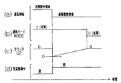
図6は、機関運転状態が成層燃焼領域から均質閉弁領域へと移行する場合のタイムチャートである。この場合、ECU92は、燃焼方式を成層燃焼から均質燃焼に切り換えてから所定時間経過後に、気流制御弁48を開弁状態から閉弁状態へと切り換える。なお、上記所定時間としては、成層燃焼から均質燃焼への切り換えに伴う燃料噴射量、燃料噴射時期、点火時期、及びスロットル開度等の制御態様の変化に基づき、実際に燃料噴射量、燃料噴射時期、点火時期、及び吸入空気量等が変化するのに必要な時間を採用することができる。
【0057】
ECU92は、負荷率KL及びエンジン回転数NEが存在する運転領域が図6(a)に示されるように成層燃焼領域から均質閉弁領域へと変化すると、運転モードMODEを図6(b)に示すように「0(成層燃焼)」から「1(均質燃焼)」へと変化させ、燃焼方式を成層燃焼から均質燃焼へと切り換える。また、ECU92は、このときに上記燃焼方式の切り換えが行われてからの経過時間を計測するためのカウンタC1を図6(c)に示すように「0」にリセットし、その後にカウンタC1の値を所定時間毎に「1」ずつ増加させる。
【0058】
そして、燃焼方式が成層燃焼から均質燃焼へと切り換えられた後、図6(c)に示すようにカウンタC1の値が上述した所定時間に対応した値である所定値aよりも大きくなると、ECU92は、図6(d)に示すように気流制御弁48を開弁状態から閉弁状態へと変化させる。これにより、燃焼室16に吸入される空気の流通面積が減少し、この吸入空気の流速が早められるとともに燃焼室16内におけるガスの乱流が生じることとなる。こうした燃焼室16内におけるガスの流動状態の変化は、燃焼方式の切り換えに伴い燃料噴射量、燃料噴射時期、点火時期、及び吸入空気量等が変化した後に生じるようになる。
【0059】
また、図7は、機関運転状態が均質閉弁領域から成層燃焼領域へと移行する場合のタイムチャートである。この場合、ECU92は、気流制御弁48を閉弁状態から開弁状態へと切り換えてから所定時間経過後に、燃焼方式を均質燃焼から成層燃焼に切り換える。なお、上記所定時間としては、気流制御弁48の閉弁状態から開弁状態への切り換えに伴い燃焼室16内のガスの流動状態が変化するのに必要な時間を採用することができる。
【0060】
ECU92は、負荷率KL及びエンジン回転数NEが存在する運転領域が図7(a)に示されるように均質閉弁領域から成層燃焼領域へと変化すると、VSV61を制御して気流制御弁48を図7(d)に示すように閉弁状態から開弁状態へと切り換える。また、ECU92は、このときに上記気流制御弁48の切り換えが行われてからの経過時間を計測するためのカウンタC2を図7(c)に示すように「0」にリセットし、その後にカウンタC2の値を所定時間毎に「1」ずつ増加させる。
【0061】
そして、気流制御弁48が閉弁状態から開弁状態へと切り換えられた後、図7(c)に示すようにカウンタC2の値が上述した所定時間に対応した値である所定値bよりも大きくなると、ECU92は、図7(b)に示すように運転モードを「1(均質燃焼)」から「0(成層燃焼)」へと切り換える。これにより、燃焼方式が均質燃焼から成層燃焼へと切り換えられ、燃料噴射量、燃料噴射時期、点火時期、スロットル開度等の制御態様が変化する。こうした制御態様の変化に伴う燃料噴射量、燃料噴射時期、点火時期、及び吸入空気量等の変化は、気流制御弁48の閉弁状態から開弁状態の切り換えに伴い燃焼室16内のガスの流動状態が変化した後に生じるようになる。
【0062】
次に、気流制御弁48の切換手順について、気流制御弁切換ルーチンを示す図4のフローチャートを参照して説明する。この気流制御弁切換ルーチンは、ECU92を通じて例えば所定時間毎の時間割り込みにて実行される。
【0063】
気流制御弁切換ルーチンにおいて、ステップS101,S102の処理は、エンジン11の運転状態が成層燃焼領域、均質閉弁領域、及び均質開弁領域のうちのいずれの運転領域にあるかを判断するためのものである。
【0064】
即ち、ECU92は、ステップS101の処理でエンジン11の運転状態が均質燃焼領域にあるか否かを判断し、ステップS102の処理で同運転状態が均質閉弁領域にあるか否かを判断する。
【0065】
そして、同運転状態が成層燃焼領域や均質開弁領域にある場合には、ステップS101とステップS102とのいずれかで否定判定がなされ、ステップS111に進む。ECU92は、ステップS111の処理として気流制御弁48の開弁を指示し、別のルーチンで気流制御弁48が開弁状態となるようVSV61を制御する。従って、エンジン11の運転状態が成層燃焼領域や均質開弁領域にある場合には、それが他の運転領域から変化してきた直後の状態であるか否かに関係なく気流制御弁48が開弁される。ステップS111の処理を実行した後には、後述するステップS110に進む。
【0066】
また、エンジン11の運転状態が均質閉弁領域にある場合には、上記ステップS101とステップS102との両方において肯定判定がなされ、ステップS103に進む。ステップS103以降の処理は、エンジン11の運転状態が成層燃焼領域から均質閉弁領域に移行する際に、気流制御弁48の開弁状態から閉弁状態への切り換えを、燃焼方式の成層燃焼から均質燃焼への切り換えに対し、所定時間だけ遅らせて実行するためのものである。
【0067】
ECU92は、ステップS103の処理で、遅延フラグF1として「1(遅延中)」がRAM95の所定領域に記憶されているか否かを判断する。この遅延フラグF1は、上述したように燃焼方式の切り換えに対し気流制御弁48の切り換えが遅延中であるか否かを判断するためのものである。そのため、遅延フラグF1は、エンジン11の運転状態が成層燃焼領域から均質閉弁領域に移行した時点から上記カウンタC1の値が所定値aよりも大きくなって気流制御弁48が閉弁状態に切り換えられるまでの間は「1(遅延中)」とされ、この切換後に「0(非遅延中)」とされる。
【0068】
エンジン11の運転状態が成層燃焼領域から均質閉弁領域に移行した後に最初にステップS103の処理が行われる際には、遅延フラグF1が「0(非遅延中)」であってステップS103で肯定判定がなされ、ステップS104に進む。ECU92は、ステップS104の処理で上記成層燃焼領域から均質閉弁領域への変化の直後か否かを判断し、否定判定であればステップS109の処理で気流制御弁48の閉弁を指示する。従って、エンジン11の運転状態が均質閉弁領域にある状態が継続されているときには、気流制御弁48が上記指示に基づき閉弁状態とされるようになる。
【0069】
また、上記ステップS104の処理において肯定判定がなされた場合には、ステップS105の処理で遅延フラグF1として「1(遅延中)」をRAM95の所定領域に記憶し、ステップS106の処理でカウンタC1の値を「0」にリセットする。その後、ステップS107に進む。なお、上記ステップS105の処理で遅延フラグF1が「1(遅延中)」にされると、次回にステップS103の処理が実行される際には否定判定がなされ、直接ステップS107に進むようになる。このステップS107の処理として、ECU92は、カウンタC1の値を「1」だけ大きくする。
【0070】
続いてECU92は、ステップS108の処理として、カウンタC1の値が所定値aよりも大きいか否か、即ちエンジン11の運転状態が成層燃焼領域から均質閉弁領域へと変化してから所定時間が経過したか否かを判断する。そして、「C1>a」でなければ気流制御弁切換ルーチンを一旦終了し、「C1>a」であればステップS109に進む。ECU92は、ステップS109の処理で気流制御弁48の閉弁を指示し、ステップS110の処理で遅延フラグF1として「0(非遅延中)」をRAM95の所定領域に記憶した後、この気流制御弁切換ルーチンを一旦終了する。
【0071】
次に、燃焼方式の決定に係わる運転モードMODEの切換手順について、運転モード切換ルーチンを示す図5のフローチャートを参照して説明する。なお、運転モード切換ルーチンは、ECU92を通じて例えば所定時間毎の時間割り込みにて実行される。
【0072】
運転モード切換ルーチンにおいて、ECU92は、ステップS201の処理として、エンジン11の運転状態が成層燃焼領域にあるか否かを判断する。そして、ステップS201で否定判定がなされると、ステップS210の処理で運転モードMODEを「1(均質燃焼)」に設定した後、ステップ209に進む。ECU92は、運転モードMODEが「1」に設定されることに基づき均質燃焼運転を実行し、燃料噴射量、燃料噴射時期、点火時期、及びスロットル開度等を均質燃焼に適したものへと制御する。
【0073】
また、上記ステップS201で肯定判定がなされると、ステップS202に進む。ステップS202以降の処理は、エンジン11の運転状態が均質閉弁領域から成層燃焼領域に以降する際、燃焼方式の均質燃焼から成層燃焼への切り換えを、気流制御弁48の閉弁状態から開弁状態への切り換えに対し、所定時間だけ遅らせて実行するためのものである。
【0074】
ECU92は、ステップS202の処理で、遅延フラグF2として「1(遅延中)」がRAM95の所定領域に記憶されているか否かを判断する。この遅延フラグF2は、上述したように気流制御弁48の切り換えに対し燃焼方式の切り替えが遅延中であるか否かを判断するためのものである。そのため、遅延フラグF2は、エンジン11の運転状態が均質閉弁領域から成層燃焼領域に移行した時点から上記カウンタC2の値が所定値bよりも大きくなって燃焼方式が成層燃焼に切り換えられるまでの間は「1(遅延中)」とされ、この切換後に「0(非遅延中)」とされる。
【0075】
エンジン11の運転状態が均質閉弁領域から成層燃焼領域に移行した後に最初にステップS202の処理が行われる際には、遅延フラグF2が「0(非遅延中)」であってステップS202で肯定判定がなされ、ステップS203に進む。ECU92は、ステップS203の処理で上記均質閉弁領域から成層燃焼領域への変化の直後が否かを判断し、否定判定であればステップS208の処理で運転モードMODEを「0(成層燃焼)」に設定する。従って、エンジン11の運転状態が成層燃焼領域にある状態が継続されているときには、運転モードMODEが「0(成層燃焼)」であることに基づき燃焼方式が成層燃焼とされるようになる。
【0076】
また、上記ステップS203の処理において肯定判定がなされた場合には、ステップS204の処理で遅延フラグF2として「1(遅延中)」をRAM95の所定領域に記憶し、ステップS205の処理でカウンタC2の値を「0」にリセットする。その後、ステップS206に進む。なお、上記ステップS204の処理で遅延フラグF2が「1(遅延中)」にされると、次回にステップS202の処理が実行される際には否定判定がなされ、直接ステップS206に進むようになる。このステップS206の処理として、ECU92は、カウンタC2の値を「1」だけ大きくする。
【0077】
続いてECU92は、ステップS207の処理として、カウンタC2の値が所定値bよりも大きいか否か、即ちエンジン11の運転状態が均質閉弁領域から成層燃焼領域へと変化してから所定時間が経過したか否かを判断する。そして、「C2>b」でなければ運転モード切換ルーチンを一旦終了し、「C2>b」であればステップS208に進む。ECU92は、ステップS208の処理で運転モードMODEを「0(成層燃焼)」に設定し、ステップS209の処理で遅延フラグF2として「0(非遅延中)」をRAM95の所定領域に記憶した後、運転モード切換ルーチンを一旦終了する。
【0078】
以上詳述した本実施形態によれば、以下に示す効果が得られるようになる。
(1)均質燃焼領域において気流制御弁48が閉弁される運転領域(均質閉弁領域)を成層燃焼領域に対し隣接させることにより、従来のように上記運転領域(均質閉弁領域)を成層燃焼領域から離して設定することに伴い同運転領域が縮小するのを回避し、この縮小に伴いエンジン11の燃費や出力に関して不利になるのを回避することができる。また、エンジン11の運転状態が成層燃焼領域と均質閉弁領域との間で移行する際、燃焼方式の切り換えと気流制御弁48の切り換えとが所定間隔をおいて行われる。そのため、上記成層燃焼領域から均質閉弁領域への移行、若しくはその逆において、燃焼方式と気流制御弁48とが同時に切り換えられることに伴いエンジン11にショックが生じるのを抑制することができる。
【0079】
(2)成層燃焼は点火プラグ41周りに可燃混合気を存在させた状態で同混合気に対して点火を行うことにより実現するため、燃焼室16内におけるガスの流動状態が混合気の燃焼に影響を及ぼし易くなる。そのため、成層燃焼運転時に気流制御弁48の開閉状態が適正でないと、燃焼室16内のガスの流動状態が混合気の燃焼に悪影響を及ぼすおそれがある。エンジン11の運転状態が成層燃焼領域から均質閉弁領域に移行する際には、燃焼方式が成層燃焼から均質燃焼に切り換えられてから、気流制御弁48が成層燃焼に適した開閉状態である開弁状態から閉弁状態へと切り換えられる。そのため、成層燃焼領域から均質閉弁領域に移行する際における成層燃焼運転時に、気流制御弁48の開閉状態が成層燃焼にとって不適切な状態(閉弁状態)になることはない。また、エンジン11の運転状態が均質閉弁領域から成層燃焼領域に移行する際には、気流制御弁48が閉弁状態から成層燃焼運に適した開閉状態である開弁状態へと切り換えられてから、燃焼方式が均質燃焼から成層燃焼へと切り換えられる。そのため、均質閉弁領域から成層燃焼領域に移行する際における成層燃焼運転時にも、気流制御弁48の開閉状態が成層燃焼にとって不適切な状態(閉弁状態)になることはない。従って、成層燃焼領域から均質閉弁領域へと移行する場合であれ、その逆であれ、それらの際の成層燃焼運転時に気流制御弁48が不適切な状態(閉弁状態)になって、燃焼室16内におけるガスの流動状態が成層燃焼に相応しくないものになるのを回避することができる。
【0080】
(3)エンジン11の運転状態が成層燃焼領域から均質閉弁領域へと移行する際、燃焼方式が切り換えられてから所定時間(所定値aに対応)が経過した後に気流制御弁48が切り換えられる。そして、上記所定時間としては、成層燃焼から均質燃焼への切り換えに伴う燃料噴射量、燃料噴射時期、点火時期、及びスロットル開度等の制御態様の変化に基づき、実際に燃料噴射量、燃料噴射時期、点火時期、及び吸入空気量等が変化するのに必要な時間が採用される。従って、気流制御弁48が上記のように切り換えられる際に、同切り換えに基づきエンジン11の良好な運転を行う上で要求される燃料噴射量、燃料噴射時期、点火時期、及びスロットル開度等が変化し、これに応じて燃料噴射弁40、イグナイタ41a、及びスロットル用モータ24等が制御されるときにショックが生じるのを的確に抑制することができる。
【0081】
(4)エンジン11の運転状態が均質閉弁領域から成層燃焼領域へと移行する際、気流制御弁48が切り換えられてから所定時間(所定値bに対応)が経過した後に燃焼方式が切り換えられる。そして、上記所定時間としては、気流制御弁48の閉弁状態から開弁状態への切り換えに伴い燃焼室16内のガスの流動状態が変化するのに必要な時間が採用される。従って、燃焼方式が上記のように切り換えられる際に、同切り換えに基づきエンジン11の良好な運転を行う上で要求される燃料噴射量、燃料噴射量、燃料噴射時期、点火時期、及びスロットル開度等が変化し、これに応じて燃料噴射弁40、イグナイタ41a、スロットル用モータ24等が制御されるときにショックが生じるのを的確に抑制することができる。
【0082】
(5)均質燃焼領域において互いに隣接する均質閉弁領域と均質開弁領域は、それらの境界に対応する負荷率KL及びエンジン回転数NEが気流制御弁48の閉弁時と開弁時とで得られるエンジントルクが等しくなる負荷率及びエンジン回転数となるよう設定される。従って、エンジン11の運転状態が均質閉弁領域と均質開弁領域との間で移行する際、気流制御弁48が閉弁状態と開弁状態との間で変化しても、その際にショックが発生するのを抑制することができるようになる。また、エンジン11の運転状態が高回転高負荷領域(均質開弁領域)にあるときには気流制御弁48が開弁されるため、吸気抵抗が低減されることによるエンジン出力の向上が図られるようになる。
【0083】
(6)上記境界は、負荷率KLを一定とした条件下で、エンジン回転数NEを気流制御弁48の閉弁時と開弁時とでエンジントルクが等しくなる値としたときの単位時間当たりの吸入空気量を求め、この吸入空気量を得ることが可能な負荷率及びエンジン回転数を計算等によって算出し、これら負荷率及びエンジン回転数に基づき設定される。そのため、少なくとも一度だけ上記単位時間当たりの吸入空気量を求めさえすれば、その吸入空気量が得られる負荷率及びエンジン回転数を計算等によって算出し、これら負荷率及びエンジン回転数に基づき簡単に上記境界を設定することができる。
【0084】
(7)また、上記単位時間当たりの吸入空気量を求めるために負荷率KLを一定にする際には、負荷率KLを最大機関負荷(全負荷)に対応した値で一定とした。エンジン11においては、全負荷としたときに安定した運転状態となり、このときに正確に単位時間当たりの吸入空気量を検出することが可能になる。そのため、上記のように負荷率KLを全負荷に対応した値で一定とした状態で求められる吸入空気量に基づき上記境界を設定することにより、この境界の設定を一層適切に行うことができるようになる。
【0085】
なお、本実施形態は、例えば以下のように変更することもできる。
・均質閉弁領域と均質開弁領域との境界を設定するのに用いられる単位時間当たりの吸入空気量を求める際、負荷率KLを最大機関負荷(全負荷)に対応する値で一定にしたが、必ずしもこのように負荷率KLを一定にする必要はない。
【0086】
・均質閉弁領域及び均質開弁領域は、それらの境界に対応する負荷率KL及びエンジン回転数NEが気流制御弁48の閉弁時と開弁時とでエンジントルクが等しくなる負荷率及びエンジン回転数となるよう設定されるが、必ずしもこうした領域の設定の仕方をする必要はない。
【0087】
・エンジン11の運転状態が成層燃焼領域と均質閉弁領域との間で移行する際の燃焼方式及び気流制御弁48の切り換えの順番を適宜変更してもよい。
・成層燃焼領域で気流制御弁48が閉弁され、この成層燃焼領域と隣接する運転領域で気流制御弁48が開弁されるエンジンに本発明を適用してもよい。
【図面の簡単な説明】
【図1】本実施形態の制御装置が適用されるエンジンの吸気系の構成を示す略図。
【図2】同エンジンの全体構成を示す略図。
【図3】上記制御装置の電気的構成を示すブロック図。
【図4】気流制御弁の切換手順を示すフローチャート。
【図5】運転モードの切換手順を示すフローチャート。
【図6】エンジンの運転状態が成層燃焼領域から均質閉弁領域に移行する際の運転領域、運転モードMODE、カウンタC1、気流制御弁の変化態様を示すタイムチャート。
【図7】エンジンの運転状態が均質閉弁領域から成層燃焼領域に移行する際の運転領域、運転モードMODE、カウンタC1、気流制御弁の変化態様を示すタイムチャート。
【図8】本実施形態の成層燃焼領域、均質燃焼領域、均質閉弁領域、及び均質開弁領域を示す図。
【図9】従来の成層燃焼領域、均質燃焼領域、及び気流制御弁が閉弁される運転領域を示す図。
【符号の説明】
11…エンジン、14c…クランクポジションセンサ、16…燃焼室、23…スロットルバルブ、24…スロットル用モータ、25…アクセルペダル、26…アクセルポジションセンサ、32…吸気通路、36…バキュームセンサ、40…燃料噴射弁、41…点火プラグ、41a…イグナイタ、48…気流制御弁、49…アクチュエータ、57…バキュームタンク、58…負圧通路、59…吸引通路、61…バキュームスイッチングバルブ(VSV)、92…電子制御ユニット(ECU)。95a…チェック弁。[0001]
BACKGROUND OF THE INVENTION
The present invention relates to a control device for an internal combustion engine.
[0002]
[Prior art]
2. Description of the Related Art In recent years, internal combustion engines such as in-vehicle engines have been put into practical use in which the combustion method is switched between stratified combustion and homogeneous combustion in accordance with engine operating conditions with the intention of improving fuel efficiency. Further, in this type of internal combustion engine, as described in, for example, “Crown, Crown Majesta New Model Car Description” issued on September 24, 1999, the gas in the combustion chamber is obtained so that a good combustion of the air-fuel mixture can be obtained. It is also known to provide an airflow control valve for changing the flow state in the intake passage of the engine.
[0003]
In the internal combustion engine shown in the above document, the stratified combustion operation is executed when the engine operation state is in the low rotation low load region (stratified combustion region), and the homogeneous combustion operation is executed in other regions (homogeneous combustion region). . The airflow control valve of the engine is opened in the high rotation / high load side region in the stratified combustion region and homogeneous combustion region, and closed in the low rotation / high load side and high rotation / low load region in the homogeneous combustion region. Will come to be. The air flow control valve opening / closing control is
-During stratified combustion operation, a combustible air-fuel mixture is formed around the spark plug without the assistance of gas flow in the combustion chamber.
[0004]
・ At low rotation and high load or high rotation and low load, close the airflow control valve to create turbulent flow in the combustion chamber to promote mixing of air and fuel, and to be sucked into the combustion chamber It is preferable to increase the intake flow efficiency by increasing the gas flow rate.
[0005]
-It is preferable to open the airflow control valve except when it is preferable to close the airflow control valve, and to suppress an increase in intake resistance accompanying the closing of the airflow control valve as much as possible.
It is based on reasons such as.
[0006]
By the way, when the engine operating state shifts between the stratified combustion region and a predetermined operation region where the airflow control valve is closed (low rotation high load side or high rotation low load side in the homogeneous combustion region), the combustion method Is switched between stratified combustion and homogeneous combustion, and the airflow control valve is switched between an open state and a closed state.
[0007]
When the combustion method is switched, the fuel injection amount, ignition timing, etc. required for good operation of the internal combustion engine change, and shocks occur when changing the fuel injection amount, ignition timing, etc. accordingly. It tends to occur. Also, when the airflow control valve is switched, the fuel injection amount, ignition timing, etc. required for good operation of the internal combustion engine change, and the fuel injection amount, ignition timing, etc. change accordingly. Shock is likely to occur.
[0008]
Therefore, when the switching of the combustion method and the switching of the airflow control valve are performed at the same time, the required fuel injection amount and ignition timing depend not only on the combustion method as described above but also on the opening / closing state of the airflow control valve. Therefore, a shock may occur depending on the control mode such as the fuel injection amount and the ignition timing.
[0009]
Therefore, in the internal combustion engine described in the above document, the predetermined operation region where the airflow control valve is closed is not homogeneously burned as shown by the broken line in FIG. 9 so that the switching of the combustion method and the switching of the airflow control valve do not occur simultaneously. Within the region, it is set apart from the stratified combustion region. In this case, for example, when the engine operating state shifts from the stratified combustion region to the predetermined operating region, the combustion method is first switched from stratified combustion to homogeneous combustion, and then the air flow control valve is closed from the open state to the closed state. Since the state is switched to the state, the occurrence of the shock as described above is suppressed.
[0010]
[Problems to be solved by the invention]
By setting the predetermined operation region in which the airflow control valve is closed as described above, the shock can surely be suppressed. However, in order to set the predetermined operation region away from the stratified combustion region, the predetermined operation region must be narrowed.
[0011]
That is, for the operation region located on the low rotation high load side of the homogeneous combustion region in the predetermined operation region, the lower limit in the load direction in FIG. 9 is set on the high load side to narrow the operation region. It is away from the combustion area. In addition, among the predetermined operation regions, for the operation region located on the high rotation low load side of the homogeneous combustion region, the engine rotation speed lower limit in FIG. 9 is set to the high rotation side to narrow the operation region. Thus, the stratified combustion region is separated from the region.
[0012]
However, if the predetermined operation region in which the airflow control valve is closed in this way is narrowed, the airflow control valve is closed in order to obtain good combustion of the air-fuel mixture in the region between the operation region and the stratified combustion region. However, the air flow control valve is opened, which is disadvantageous in terms of fuel consumption and output of the internal combustion engine. And such a malfunction becomes so remarkable that the period when an engine operating state exists in said area | region becomes long.
[0013]
The present invention has been made in view of such circumstances, and its object is to provide a shock associated with the simultaneous switching of the combustion method and the airflow control valve without detrimental to the fuel consumption and output of the internal combustion engine. An object of the present invention is to provide a control device for an internal combustion engine that can be suppressed.
[0014]
[Means for Solving the Problems]
In the following, means for achieving the above object and its effects are described.
(1) The invention according to
[0015]
According to the above configuration, the predetermined operation region is prevented from being reduced by making the predetermined operation region adjacent to the stratified combustion region, and the airflow control valve is interposed between the stratified combustion region and the predetermined operation region along with the reduction. However, it is possible to avoid the occurrence of an unfavorable open / close state with respect to the fuel consumption and output of the internal combustion engine. Further, when the engine operating state shifts between the stratified combustion region and the predetermined operation region, the combustion method and the airflow control valve are switched at predetermined intervals, so that the combustion method and the airflow control valve It is possible to suppress the occurrence of a shock in the internal combustion engine due to the simultaneous switching.In addition, as a method of switching the combustion method and the airflow control valve at a predetermined interval, for example, a method of performing the other switching after a predetermined time elapses after one switching is performed can be employed.
Further, during the stratified combustion operation, the flow state of the gas in the combustion chamber tends to affect the combustion of the air-fuel mixture. According to the above configuration, when the engine operating state shifts from the stratified combustion region to the predetermined operating region, the air flow control valve is switched after the combustion method is switched from stratified combustion to homogeneous combustion. The open / close state of the airflow control valve does not become inappropriate during the stratified combustion operation. Further, when the engine operating state shifts from the predetermined operation region to the stratified combustion region, the air flow control valve is switched and then the combustion method is switched from homogeneous combustion to stratified combustion. The air flow control valve does not open or close inappropriately. Therefore, whether the engine operating state shifts from the stratified combustion operation to the predetermined operating region or vice versa, the open / close state of the air flow control valve becomes inappropriate during the stratified combustion operation, and the gas flow state in the combustion chamber becomes It is possible to avoid becoming unsuitable for stratified combustion.
[0016]
(2) The invention according to claim 2 is applied to an internal combustion engine in which the combustion system is switched between stratified combustion and homogeneous combustion based on the engine operating state, and opens and closes an air flow control valve provided in the intake passage of the engine. In a control device for an internal combustion engine that changes the flow state of gas in the combustion chamber through control, a predetermined operating region in which the open / close state of the airflow control valve is different from that when the engine operating state is in the stratified combustion region. Is set adjacent to the stratified combustion region in the homogeneous combustion region, and this is homogenized for a specific operation region where the open / close state of the airflow control valve is the same as when the engine operation state is in the stratified combustion region. A setting means that is set in the combustion region adjacent to the predetermined operation region, and when the engine operating state shifts between the stratified combustion region and the predetermined operation region. The switching of the combustion method and the switching of the open / closed state are performed at a predetermined interval, and the switching of the combustion method and the switching of the combustion method when the engine operating state transitions between the predetermined operating region and the specific operating region. The gist of the invention is that it comprises control means for switching the open / closed state without leaving the predetermined interval.
[0017]
(3) The invention according to claim 3 is applied to an internal combustion engine in which the combustion system is switched between stratified combustion and homogeneous combustion based on the operating state of the engine, and opens and closes an airflow control valve provided in the intake passage of the engine. In a control device for an internal combustion engine that changes the gas flow state in the combustion chamber through control, a predetermined operation region in which the airflow control valve is opened and closed differently from when the engine operation state is in the stratified combustion region Setting means for setting the combustion region adjacent to the stratified combustion region, and when the engine operating state shifts from the stratified combustion region to the predetermined operating region, the combustion method is first switched. The gist of the invention is that it comprises control means for switching the open / close state based on the fact that the elapsed time has reached a preset determination time.
[0018]
(4) The invention described in claim 4 is applied to an internal combustion engine in which the combustion system is switched between stratified combustion and homogeneous combustion based on the operating state of the engine, and opens and closes an air flow control valve provided in the intake passage of the engine. In a control device for an internal combustion engine that changes the gas flow state in the combustion chamber through control, a predetermined operation region in which the airflow control valve is opened and closed differently from when the engine operation state is in the stratified combustion region Setting means for setting the combustion zone so as to be adjacent to the stratified combustion region, and when the engine operating state shifts from the predetermined operating region to the stratified combustion region, first the switching of the open / close state is performed. The gist of the invention is that it comprises control means for switching the combustion method based on the fact that the elapsed time has reached a preset determination time.
[0019]
(5) The invention according to claim 5 is applied to an internal combustion engine in which the combustion system is switched between stratified combustion and homogeneous combustion based on the operating state of the engine, and opens and closes an air flow control valve provided in the intake passage of the engine. In a control device for an internal combustion engine that changes the gas flow state in the combustion chamber through control, a predetermined operation region in which the airflow control valve is opened and closed differently from when the engine operation state is in the stratified combustion region Setting means for setting the combustion region adjacent to the stratified combustion region, and when the engine operating state shifts from the stratified combustion region to the predetermined operating region, the combustion method is first switched. Based on the fact that the elapsed time has reached a preset first determination time, the switching of the open / close state is performed, and the engine operation state is changed from the predetermined operation region to the stratified combustion. First, when switching to the region, the switching of the open / close state is performed, and the elapsed time from the switching has reached the second determination time set in advance as a value different from the first determination time. The gist of the present invention is to provide a control means for switching the combustion method.
[0020]
(6) The invention according to claim 6 is the control device for an internal combustion engine according to any one of
According to the above configuration, in an internal combustion engine that performs stratified combustion without helping the gas flow in the combustion chamber, the engine operating state can be compared with the stratified combustion region without detrimental to the fuel consumption and output of the engine. The shock at the time of shifting between the predetermined operation areas can be suppressed.
[0021]
(7) The invention according to claim 7 is applied to an internal combustion engine in which the combustion system is switched between stratified combustion and homogeneous combustion based on the operating state of the engine, and opens and closes an air flow control valve provided in the intake passage of the engine. In a control device for an internal combustion engine that changes the gas flow state in the combustion chamber through control, a predetermined operation region in which the airflow control valve is opened and closed differently from when the engine operation state is in the stratified combustion region Setting means for setting adjacent to the stratified combustion region in the combustion region, and switching of the combustion method and the air flow control when the engine operating state transitions between the stratified combustion region and the predetermined operating region Control means for performing switching of the valve at a predetermined interval, the internal combustion engine performs stratified combustion without assistance of gas flow in the combustion chamber, and the air flow control valve is stratified fuel And the setting means controls the engine load and the engine speed so that another operating region where the airflow control valve opens is adjacent to the predetermined operating region. And set the engine load and engine speed corresponding to the boundary between the predetermined operation region and the other operation region at the time of opening and closing of the air flow control valve. The gist is that the engine load and the engine speed at which the torque obtained in (1) is equal are obtained.
[0022]
According to the above configuration, the predetermined operation region is prevented from being reduced by making the predetermined operation region adjacent to the stratified combustion region, and the airflow control valve is interposed between the stratified combustion region and the predetermined operation region along with the reduction. However, it is possible to avoid the occurrence of an unfavorable open / close state with respect to the fuel consumption and output of the internal combustion engine. Further, when the engine operating state shifts between the stratified combustion region and the predetermined operation region, the combustion method and the airflow control valve are switched at predetermined intervals, so that the combustion method and the airflow control valve It is possible to suppress the occurrence of a shock in the internal combustion engine due to the simultaneous switching.
Also,According to the above configuration, the air flow control valve is opened when the internal combustion engine is under high rotation and high load, so that the engine output can be improved by reducing the intake resistance. Further, the engine operating state is the predetermined operating range and thespecificWhen transitioning between operating regions, the airflow control valve changes between the closed state and the open state. However, the predetermined operating range and the abovespecificSince the engine load and the engine speed corresponding to the boundary with the operation region are values at which the torque obtained when the air flow control valve is opened and when the air flow control valve is closed, the open / close state of the air flow control valve is as described above. It is possible to suppress the occurrence of shock when changing.
[0023]
(8) The invention according to claim 8 is the control device for an internal combustion engine according to claim 7, wherein the setting means sets the engine speed under the condition that the engine load is constant to close the air flow control valve. Based on the intake air amount per unit time when the torque obtained at the time of opening and the valve opening is equal to each other, the predetermined operating range is determined by the engine load and the engine speed at which the intake air amount can be obtained. The gist is to set a boundary with the other operation region.
[0024]
According to the above configuration, if the intake air amount per unit time is obtained at least once, the engine load and engine speed at which the intake air amount is obtained are calculated by calculation, and the calculated engine load is calculated. The boundary can be easily set based on the engine speed.
When the engine load is made constant in order to obtain the intake air amount of the unit time value, it is preferable to make the internal combustion engine constant at all loads. This is because the internal combustion engine is in a stable state at full load, and at this time, it is possible to accurately detect the intake air amount per unit time. By setting the boundary based on the accurate intake air amount per unit time, the boundary can be set more appropriately.
[0025]
(9) The invention according to claim 9 is the control apparatus for an internal combustion engine according to any one of
(10) The invention according to claim 10 is the control apparatus for an internal combustion engine according to claim 9, wherein the setting means includes the stratified charge combustion region and the stratified combustion region on the operation region defined by the engine load and the engine speed. The gist is to set each of a predetermined operation region and the specific operation region, to set the stratified combustion region on the low rotation and low load side, and to set the specific operation region on the high rotation and high load side.
[0026]
DETAILED DESCRIPTION OF THE INVENTION
Hereinafter, an embodiment in which the present invention is applied to an in-line four-cylinder automobile direct injection gasoline engine will be described with reference to FIGS.
[0027]
As shown in FIG. 2, in the
[0028]
An
[0029]
In the
[0030]
Next, the detailed structure of the intake system of the
As shown in FIG. 1, the
[0031]
The
[0032]
On the other hand, in the
[0033]
The
[0034]
Next, a control device for performing switching control for changing the combustion mode of the
[0035]
This control device includes an electronic control unit (hereinafter referred to as ECU) 92 that performs operation control of the
[0036]
Here, the
[0037]
A crank
[0038]
The
[0039]
Then, the
[0040]
As can be seen from this figure, when the operating state of the
[0041]
The switching of the combustion method between stratified combustion and homogeneous combustion is a value of an operation mode MODE set through the
[0042]
Since the stratified combustion and the homogeneous combustion have different forms of the air-fuel mixture in the
[0043]
Further, the
[0044]
The opening / closing control of the
In the stratified combustion operation, a combustible air-fuel mixture is formed around the
[0045]
In the homogeneous valve closing region, the
[0046]
In an area other than the homogeneous valve closing area in the homogeneous combustion area, it is preferable to suppress an increase in intake resistance accompanying the closing of the
It is based on reasons such as.
[0047]
The flow state of the gas in the
[0048]
The homogeneous combustion region shown in FIG. 8 is divided into a homogeneously closed region where the
[0049]
When setting the boundary between the homogeneous valve closing region and the homogeneous valve opening region, first, the engine speed NE is set under the condition that the load factor KL is constant at a value corresponding to, for example, the maximum engine load (full load). Is determined as a value at which the engine torque becomes equal when the
[0050]
By setting the homogeneous valve closing region and the homogeneous valve opening region and their boundaries in this way, the engine operating conditions such as the load factor KL and the engine speed NE are between the homogeneous valve closing region and the homogeneous valve opening region. When the air
[0051]
Further, the engine operating state may not only shift between the homogeneous valve closing region and the homogeneous valve opening region, but may also shift between the stratified combustion region and the homogeneous valve closing region. At that time, the combustion system of the
[0052]
When the combustion method is switched as described above, the fuel injection amount, the fuel injection timing, the ignition timing, the throttle opening, and the like required for good operation of the
[0053]
Therefore, when the engine operating state shifts between the stratified combustion region and the homogeneous valve closing region, if the switching of the combustion method and the switching of the
[0054]
Therefore, in the present embodiment, when the engine operating state shifts between the stratified combustion region and the homogeneous valve closing region, the switching of the combustion method and the switching of the
[0055]
Next, an outline of the switching control of the combustion system and the
[0056]
FIG. 6 is a time chart when the engine operating state shifts from the stratified combustion region to the homogeneous valve closing region. In this case, the
[0057]
When the operation region where the load factor KL and the engine speed NE exist changes from the stratified combustion region to the homogeneous valve closing region as shown in FIG. 6A, the
[0058]
Then, after the combustion method is switched from stratified combustion to homogeneous combustion, as shown in FIG. 6 (c), when the value of the counter C1 becomes larger than a predetermined value a which is a value corresponding to the predetermined time described above, the
[0059]
FIG. 7 is a time chart when the engine operating state shifts from the homogeneous valve closing region to the stratified combustion region. In this case, the
[0060]
When the operating region where the load factor KL and the engine speed NE are present changes from the homogeneously closed valve region to the stratified combustion region as shown in FIG. 7A, the
[0061]
Then, after the
[0062]
Next, the switching procedure of the
[0063]
In the airflow control valve switching routine, the processing in steps S101 and S102 is for determining whether the operation state of the
[0064]
That is, the
[0065]
If the operation state is in the stratified combustion region or the homogeneous valve opening region, a negative determination is made in either step S101 or step S102, and the process proceeds to step S111. The
[0066]
When the operating state of the
[0067]
In step S103, the
[0068]
When the process of step S103 is performed for the first time after the operating state of the
[0069]
If an affirmative determination is made in step S104, "1 (delayed)" is stored in the predetermined area of
[0070]
Subsequently, in step S108, the
[0071]
Next, the procedure for switching the operation mode MODE related to the determination of the combustion method will be described with reference to the flowchart of FIG. 5 showing the operation mode switching routine. The operation mode switching routine is executed through the
[0072]
In the operation mode switching routine, the
[0073]
If a positive determination is made in step S201, the process proceeds to step S202. In the processing after step S202, when the operation state of the
[0074]
In the process of step S202, the
[0075]
When the process of step S202 is performed for the first time after the operating state of the
[0076]
If an affirmative determination is made in step S203, "1 (delayed)" is stored in the predetermined area of
[0077]
Subsequently, as a process of step S207, the
[0078]
According to the embodiment described in detail above, the following effects can be obtained.
(1) The operation region (homogeneous valve closing region) in which the
[0079]
(2) Since stratified combustion is realized by igniting the air-fuel mixture in a state where a combustible air-fuel mixture exists around the
[0080]
(3) When the operating state of the
[0081]
(4) When the operating state of the
[0082]
(5) The homogeneous valve closing region and the homogeneous valve opening region that are adjacent to each other in the homogeneous combustion region are such that the load factor KL and the engine speed NE corresponding to the boundary are different between when the air
[0083]
(6) The above boundary is per unit time when the engine speed NE is set to a value that makes the engine torque equal when the air
[0084]
(7) When the load factor KL is made constant in order to obtain the intake air amount per unit time, the load factor KL is made constant at a value corresponding to the maximum engine load (full load). The
[0085]
In addition, this embodiment can also be changed as follows, for example.
-When determining the intake air volume per unit time used to set the boundary between the homogeneous valve closing region and the homogeneous valve opening region, the load factor KL is made constant at a value corresponding to the maximum engine load (full load). However, it is not always necessary to make the load factor KL constant in this way.
[0086]
The homogeneous valve closing region and the homogeneous valve opening region are such that the load factor KL and the engine speed NE corresponding to the boundary between them are equal to each other when the air
[0087]
The order of switching the combustion method and the
The present invention may be applied to an engine in which the
[Brief description of the drawings]
FIG. 1 is a schematic diagram showing a configuration of an intake system of an engine to which a control device of an embodiment is applied.
FIG. 2 is a schematic diagram showing the overall configuration of the engine.
FIG. 3 is a block diagram showing an electrical configuration of the control device.
FIG. 4 is a flowchart showing a procedure for switching an airflow control valve.
FIG. 5 is a flowchart showing a procedure for switching operation modes.
FIG. 6 is a time chart showing a change mode of an operation region, an operation mode MODE, a counter C1, and an airflow control valve when the operation state of the engine shifts from a stratified combustion region to a homogeneous valve closing region.
FIG. 7 is a time chart showing a change mode of an operation region, an operation mode MODE, a counter C1, and an airflow control valve when the operation state of the engine shifts from a homogeneous valve closing region to a stratified combustion region.
FIG. 8 is a diagram showing a stratified combustion region, a homogeneous combustion region, a homogeneous valve closing region, and a homogeneous valve opening region of the present embodiment.
FIG. 9 is a diagram showing a conventional stratified combustion region, a homogeneous combustion region, and an operation region in which an airflow control valve is closed.
[Explanation of symbols]
DESCRIPTION OF
Claims (10)
機関運転状態が成層燃焼領域にあるときとは前記気流制御弁の開閉状態が異なる状態になる所定運転領域を、均質燃焼領域内に前記成層燃焼領域と隣接するように設定する設定手段と、 Setting means for setting a predetermined operation region in which the open / close state of the airflow control valve is different from that when the engine operation state is in the stratified combustion region to be adjacent to the stratified combustion region in the homogeneous combustion region;
機関運転状態が前記成層燃焼領域と前記所定運転領域との間で移行する際に、前記燃焼方式の切り換えと前記気流制御弁の開閉状態の切り換えとを所定の間隔をおいて行うとともに、機関運転状態が前記成層燃焼領域から前記所定運転領域に移行する際には燃焼方式を切り換えてから前記気流制御弁の開閉状態を切り換え、機関運転状態が前記所定運転領域から前記成層燃焼領域に移行する際には前記気流制御弁の開閉状態を切り換えてから燃焼方式を切り換える制御手段とを備える When the engine operation state shifts between the stratified combustion region and the predetermined operation region, the combustion method is switched and the air flow control valve is opened and closed at a predetermined interval, and the engine operation is performed. When the state shifts from the stratified combustion region to the predetermined operation region, the combustion method is switched and then the air flow control valve is switched to open and close, and the engine operation state shifts from the predetermined operation region to the stratified combustion region. Comprises control means for switching the combustion method after switching the open / close state of the airflow control valve.
ことを特徴とする内燃機関の制御装置。 A control device for an internal combustion engine.
機関運転状態が成層燃焼領域にあるときとは前記気流制御弁の開閉状態が異なるものになる所定運転領域について、これを均質燃焼領域内において前記成層燃焼領域と隣接するところに設定し、且つ機関運転状態が成層燃焼領域にあるときと前記気流制御弁の開閉状態が同じものになる特定運転領域について、これを均質燃焼領域内において前記所定運転領域と隣接するところに設定する設定手段と、 A predetermined operating region in which the opening / closing state of the airflow control valve is different from that when the engine operating state is in the stratified combustion region is set adjacent to the stratified combustion region in the homogeneous combustion region, and the engine A setting means for setting the specific operation region in which the open / close state of the airflow control valve is the same as when the operation state is in the stratified combustion region to be adjacent to the predetermined operation region in the homogeneous combustion region;
機関運転状態が前記成層燃焼領域と前記所定運転領域との間で移行するときに前記燃焼方式の切り換えと前記開閉状態の切り換えとを所定の間隔をおいて行うとともに、機関運転状態が前記所定運転領域と前記特定運転領域との間で移行するときに前記燃焼方式の切り換えと前記開閉状態の切り換えとを前記所定の間隔をおくことなく行う制御手段とを備える When the engine operating state shifts between the stratified combustion region and the predetermined operating region, the switching of the combustion method and the switching of the open / closed state are performed at a predetermined interval, and the engine operating state is the predetermined operation. Control means for performing switching of the combustion method and switching of the open / closed state without leaving the predetermined interval when transitioning between the region and the specific operation region
ことを特徴とする内燃機関の制御装置。 A control device for an internal combustion engine.
機関運転状態が成層燃焼領域にあるときとは前記気流制御弁の開閉状態が異なる状態になる所定運転領域を、均質燃焼領域内に前記成層燃焼領域と隣接するように設定する設定手段と、 Setting means for setting a predetermined operation region in which the open / close state of the airflow control valve is different from that when the engine operation state is in the stratified combustion region to be adjacent to the stratified combustion region in the homogeneous combustion region;
機関運転状態が前記成層燃焼領域から前記所定運転領域に移行するときにまずは前記燃焼方式の切り換えを行い、この切り換えからの経過時間が予め設定された判定時間に達したことに基づいて前記開閉状態の切り換えを行う制御手段とを備える When the engine operating state shifts from the stratified combustion region to the predetermined operating region, the combustion method is first switched, and the open / close state is determined based on the fact that the elapsed time from the switching has reached a preset determination time. Control means for switching between
ことを特徴とする内燃機関の制御装置。 A control device for an internal combustion engine.
機関運転状態が成層燃焼領域にあるときとは前記気流制御弁の開閉状態が異なる状態になる所定運転領域を、均質燃焼領域内に前記成層燃焼領域と隣接するように設定する設定手段と、 Setting means for setting a predetermined operation region in which the open / close state of the airflow control valve is different from that when the engine operation state is in the stratified combustion region to be adjacent to the stratified combustion region in the homogeneous combustion region;
機関運転状態が前記所定運転領域から前記成層燃焼領域に移行するときにまずは前記開閉状態の切り換えを行い、この切り換えからの経過時間が予め設定された判定時間に達したことに基づいて前記燃焼方式の切り換えを行う制御手段とを備える When the engine operating state shifts from the predetermined operating region to the stratified combustion region, first the switching of the open / close state is performed, and the combustion method is based on the fact that the elapsed time from the switching has reached a preset determination time Control means for switching between
ことを特徴とする内燃機関の制御装置。 A control device for an internal combustion engine.
機関運転状態が成層燃焼領域にあるときとは前記気流制御弁の開閉状態が異なる状態になる所定運転領域を、均質燃焼領域内に前記成層燃焼領域と隣接するように設定する設定手段と、 Setting means for setting a predetermined operation region in which the open / close state of the airflow control valve is different from that when the engine operation state is in the stratified combustion region to be adjacent to the stratified combustion region in the homogeneous combustion region;
機関運転状態が前記成層燃焼領域から前記所定運転領域に移行するときにまずは前記燃焼方式の切り換えを行い、この切り換えからの経過時間が予め設定された第1の判定時間に達したことに基づいて前記開閉状態の切り換えを行うとともに、機関運転状態が前記所定運転領域から前記成層燃焼領域に移行するときにまずは前記開閉状態の切り換えを行い、この切り換えからの経過時間が前記第1の判定時間とは異なる値として予め設定された第2の判定時間に達したことに基づいて前記燃焼方式の切り換えを行う制御手段とを備える When the engine operating state shifts from the stratified combustion region to the predetermined operation region, the combustion method is first switched, and the elapsed time from the switching has reached a first determination time set in advance. When the engine operating state shifts from the predetermined operating region to the stratified combustion region, the switching of the opening / closing state is performed first, and the elapsed time from this switching is the first determination time. Comprises a control means for switching the combustion method based on reaching a second determination time set in advance as a different value.
ことを特徴とする内燃機関の制御装置。 A control device for an internal combustion engine.
前記内燃機関は成層燃焼を燃焼室内でのガス流の助けをかりることなく行うものであって、前記気流制御弁は成層燃焼領域で開弁されるとともに前記所定運転領域で閉弁される The internal combustion engine performs stratified combustion without assisting the gas flow in the combustion chamber, and the air flow control valve is opened in the stratified combustion region and closed in the predetermined operation region.
ことを特徴とする内燃機関の制御装置。 A control device for an internal combustion engine.
機関運転状態が成層燃焼領域にあるときとは前記気流制御弁の開閉状態が異なる状態になる所定運転領域を、均質燃焼領域内に前記成層燃焼領域と隣接するように設定する設定手段と、 Setting means for setting a predetermined operation region in which the open / close state of the airflow control valve is different from that when the engine operation state is in the stratified combustion region to be adjacent to the stratified combustion region in the homogeneous combustion region;
機関運転状態が前記成層燃焼領域と前記所定運転領域との間で移行する際に、前記燃焼方式の切り換えと前記気流制御弁の切り換えとを所定間隔をおいて行う制御手段とを備え、 Control means for performing switching of the combustion method and switching of the airflow control valve at a predetermined interval when the engine operating state transitions between the stratified combustion region and the predetermined operating region;
前記内燃機関は成層燃焼を燃焼室内でのガス流の助けをかりることなく行うものであって、前記気流制御弁は成層燃焼領域で開弁されるとともに前記所定運転領域で閉弁され、 The internal combustion engine performs stratified combustion without the aid of gas flow in the combustion chamber, and the airflow control valve is opened in the stratified combustion region and closed in the predetermined operation region,
前記設定手段は、前記気流制御弁が開弁する別の運転領域を前記所定運転領域と隣接するように機関負荷及び機関回転数に基づき均質燃焼領域の高回転高負荷側に設定し、前記所定運転領域と前記別の運転領域との境界に対応する機関負荷及び機関回転数を前記気流制御弁の開弁時と閉弁時とで得られるトルクが等しくなる機関負荷及び機関回転数とするものである The setting means sets another operating region where the airflow control valve opens to the high rotation high load side of the homogeneous combustion region based on the engine load and the engine speed so as to be adjacent to the predetermined operating region, The engine load and engine speed corresponding to the boundary between the operating area and the other operating area are set to the engine load and engine speed at which the torque obtained when the air flow control valve is opened and closed is equal. Is
ことを特徴とする内燃機関の制御装置。 A control device for an internal combustion engine.
前記設定手段は、機関負荷を一定とした条件下で機関回転数を前記気流制御弁の閉弁時と開弁時とで得られるトルクが等しくなる値としたときの単位時間当たりの吸入空気量に基づき、その吸入空気量を得ることが可能な機関負荷及び機関回転数によって前記所定運転領域と前記別の運転領域との境界を設定する The setting means is configured such that the amount of intake air per unit time when the engine speed is a value at which the torque obtained when the airflow control valve is closed and when the airflow control valve is opened is equal under a condition where the engine load is constant. The boundary between the predetermined operation region and the other operation region is set based on the engine load and the engine speed capable of obtaining the intake air amount based on
ことを特徴とする内燃機関の制御装置。 A control device for an internal combustion engine.
前記設定手段は、前記気流制御弁が開弁する運転領域である特定運転領域と前記気流制御弁が閉弁する前記所定運転領域とが互いに隣接する態様でこれら運転領域を前記均質燃焼領域内に設定し、且つ前記所定運転領域を前記成層燃焼領域と前記特定運転領域との間に設定する The setting means is configured so that a specific operation region that is an operation region where the airflow control valve is opened and the predetermined operation region where the airflow control valve is closed are adjacent to each other in the homogeneous combustion region. And setting the predetermined operation region between the stratified combustion region and the specific operation region
ことを特徴とする内燃機関の制御装置。 A control device for an internal combustion engine.
前記設定手段は、機関負荷及び機関回転数により規定される運転領域上に前記成層燃焼領域及び前記所定運転領域及び前記特定運転領域のそれぞれを設定し、且つ低回転低負荷側に前記成層燃焼領域を設定し、且つ高回転高負荷側に前記特定運転領域を設定する The setting means sets the stratified combustion region, the predetermined operation region, and the specific operation region on an operation region defined by an engine load and an engine speed, and the stratified combustion region on a low rotation and low load side. And set the specific operating area on the high rotation and high load side.
ことを特徴とする内燃機関の制御装置。 A control device for an internal combustion engine.
Priority Applications (1)
| Application Number | Priority Date | Filing Date | Title |
|---|---|---|---|
| JP2000259113A JP4337247B2 (en) | 2000-08-29 | 2000-08-29 | Control device for internal combustion engine |
Applications Claiming Priority (1)
| Application Number | Priority Date | Filing Date | Title |
|---|---|---|---|
| JP2000259113A JP4337247B2 (en) | 2000-08-29 | 2000-08-29 | Control device for internal combustion engine |
Publications (2)
| Publication Number | Publication Date |
|---|---|
| JP2002070613A JP2002070613A (en) | 2002-03-08 |
| JP4337247B2 true JP4337247B2 (en) | 2009-09-30 |
Family
ID=18747330
Family Applications (1)
| Application Number | Title | Priority Date | Filing Date |
|---|---|---|---|
| JP2000259113A Expired - Fee Related JP4337247B2 (en) | 2000-08-29 | 2000-08-29 | Control device for internal combustion engine |
Country Status (1)
| Country | Link |
|---|---|
| JP (1) | JP4337247B2 (en) |
Families Citing this family (4)
| Publication number | Priority date | Publication date | Assignee | Title |
|---|---|---|---|---|
| JP4126942B2 (en) * | 2002-04-05 | 2008-07-30 | 株式会社デンソー | Internal combustion engine control device |
| JP2007024009A (en) * | 2005-07-21 | 2007-02-01 | Jomo Technical Research Center Co Ltd | Internal combustion engine |
| JP6414128B2 (en) | 2016-04-19 | 2018-10-31 | トヨタ自動車株式会社 | Internal combustion engine |
| JP7131172B2 (en) * | 2018-07-26 | 2022-09-06 | マツダ株式会社 | Compression ignition engine controller |
-
2000
- 2000-08-29 JP JP2000259113A patent/JP4337247B2/en not_active Expired - Fee Related
Also Published As
| Publication number | Publication date |
|---|---|
| JP2002070613A (en) | 2002-03-08 |
Similar Documents
| Publication | Publication Date | Title |
|---|---|---|
| JP4012893B2 (en) | Control device for internal combustion engine | |
| JP4306642B2 (en) | Internal combustion engine control system | |
| US6237562B1 (en) | Method of controlling compression ignition internal combustion engine | |
| JPH1122533A (en) | Control device for direct injection spark ignition internal combustion engine | |
| JP2007016685A (en) | Internal combustion engine control device | |
| WO2010114127A1 (en) | Control system for internal combustion engine | |
| CN107191284B (en) | Engine control device | |
| CN112166245B (en) | Control device for internal combustion engine and control method for internal combustion engine | |
| JP4366855B2 (en) | In-cylinder injection internal combustion engine control device | |
| JP2008019729A (en) | Control device of cylinder injection type engine | |
| US6003489A (en) | Fuel injection control device of in-cylinder type internal combustion engine | |
| US20160348606A1 (en) | Control apparatus for internal combustion engine | |
| JP4337247B2 (en) | Control device for internal combustion engine | |
| JP2006299992A (en) | Control system of internal combustion engine | |
| JP4453187B2 (en) | Control device for internal combustion engine | |
| JP2006132399A (en) | Control device and control method for an engine with supercharger | |
| JP4339599B2 (en) | In-cylinder injection internal combustion engine control device | |
| JP3661407B2 (en) | Control device for internal combustion engine | |
| JP4220736B2 (en) | Start control device for spark ignition type internal combustion engine | |
| JP3879270B2 (en) | Negative pressure control device for in-vehicle internal combustion engine | |
| JP3546742B2 (en) | Intake air amount control device for internal combustion engine | |
| JP3491019B2 (en) | Idle rotation learning control system for electronically controlled throttle internal combustion engine | |
| JP3613658B2 (en) | Fuel injection control device for multi-cylinder internal combustion engine | |
| JP3279208B2 (en) | Combustion control device for internal combustion engine | |
| JP3680505B2 (en) | Fuel injection control device for direct-injection spark-ignition internal combustion engine |
Legal Events
| Date | Code | Title | Description |
|---|---|---|---|
| A621 | Written request for application examination |
Free format text: JAPANESE INTERMEDIATE CODE: A621 Effective date: 20061222 |
|
| A131 | Notification of reasons for refusal |
Free format text: JAPANESE INTERMEDIATE CODE: A131 Effective date: 20081224 |
|
| A977 | Report on retrieval |
Free format text: JAPANESE INTERMEDIATE CODE: A971007 Effective date: 20081225 |
|
| A521 | Written amendment |
Free format text: JAPANESE INTERMEDIATE CODE: A523 Effective date: 20090223 |
|
| TRDD | Decision of grant or rejection written | ||
| A01 | Written decision to grant a patent or to grant a registration (utility model) |
Free format text: JAPANESE INTERMEDIATE CODE: A01 Effective date: 20090609 |
|
| A01 | Written decision to grant a patent or to grant a registration (utility model) |
Free format text: JAPANESE INTERMEDIATE CODE: A01 |
|
| A61 | First payment of annual fees (during grant procedure) |
Free format text: JAPANESE INTERMEDIATE CODE: A61 Effective date: 20090622 |
|
| R151 | Written notification of patent or utility model registration |
Ref document number: 4337247 Country of ref document: JP Free format text: JAPANESE INTERMEDIATE CODE: R151 |
|
| FPAY | Renewal fee payment (event date is renewal date of database) |
Free format text: PAYMENT UNTIL: 20120710 Year of fee payment: 3 |
|
| FPAY | Renewal fee payment (event date is renewal date of database) |
Free format text: PAYMENT UNTIL: 20130710 Year of fee payment: 4 |
|
| LAPS | Cancellation because of no payment of annual fees |