JP4336323B2 - Seawater exchange caisson - Google Patents

Seawater exchange caisson Download PDF

Info

Publication number
JP4336323B2
JP4336323B2 JP2005056303A JP2005056303A JP4336323B2 JP 4336323 B2 JP4336323 B2 JP 4336323B2 JP 2005056303 A JP2005056303 A JP 2005056303A JP 2005056303 A JP2005056303 A JP 2005056303A JP 4336323 B2 JP4336323 B2 JP 4336323B2
Authority
JP
Japan
Prior art keywords
seawater
breakwater
revetment
caisson
sea
Prior art date
Legal status (The legal status is an assumption and is not a legal conclusion. Google has not performed a legal analysis and makes no representation as to the accuracy of the status listed.)
Expired - Fee Related
Application number
JP2005056303A
Other languages
Japanese (ja)
Other versions
JP2006241751A (en
Inventor
保人 片岡
威博 中岡
Current Assignee (The listed assignees may be inaccurate. Google has not performed a legal analysis and makes no representation or warranty as to the accuracy of the list.)
Kobe Steel Ltd
Original Assignee
Kobe Steel Ltd
Priority date (The priority date is an assumption and is not a legal conclusion. Google has not performed a legal analysis and makes no representation as to the accuracy of the date listed.)
Filing date
Publication date
Application filed by Kobe Steel Ltd filed Critical Kobe Steel Ltd
Priority to JP2005056303A priority Critical patent/JP4336323B2/en
Publication of JP2006241751A publication Critical patent/JP2006241751A/en
Application granted granted Critical
Publication of JP4336323B2 publication Critical patent/JP4336323B2/en
Expired - Fee Related legal-status Critical Current
Anticipated expiration legal-status Critical

Links

Images

Classifications

    • YGENERAL TAGGING OF NEW TECHNOLOGICAL DEVELOPMENTS; GENERAL TAGGING OF CROSS-SECTIONAL TECHNOLOGIES SPANNING OVER SEVERAL SECTIONS OF THE IPC; TECHNICAL SUBJECTS COVERED BY FORMER USPC CROSS-REFERENCE ART COLLECTIONS [XRACs] AND DIGESTS
    • Y02TECHNOLOGIES OR APPLICATIONS FOR MITIGATION OR ADAPTATION AGAINST CLIMATE CHANGE
    • Y02ATECHNOLOGIES FOR ADAPTATION TO CLIMATE CHANGE
    • Y02A10/00TECHNOLOGIES FOR ADAPTATION TO CLIMATE CHANGE at coastal zones; at river basins
    • Y02A10/11Hard structures, e.g. dams, dykes or breakwaters

Description

本発明は、護岸と防波堤とで形成されて港湾、漁港等を構成する海水交換型ケーソンの改善に係り、より詳しくは、護岸や防波堤に衝突する海水の流れを利用して、海水の交換を促進させることにより、港湾海域における海水の水質を効果的に浄化する海水交換型ケーソンに関する。   The present invention relates to improvement of a seawater exchange caisson formed by a seawall and a breakwater to form a port, a fishing port, etc., and more specifically, the seawater exchange using the flow of seawater that collides with a seawall or a breakwater. The present invention relates to a seawater exchange caisson that effectively purifies the quality of seawater in a port sea area by promoting it.

海水の入れ替わりが緩慢な港湾海域では、海水の密度成層の形成を概念的に示す断面図の図26に示すように、河川流入や降水等による淡水が滞留しやすい上、太陽光等により表層水の水温が上昇しやすいため、表層の海水密度が小さくなる傾向にある。これが進行すると表層と底層の海水密度差が大きくなり、いわゆる密度成層が形成される。   In harbor areas where the replacement of seawater is slow, fresh water due to river inflow and precipitation tends to stay and surface water is generated by sunlight, etc., as shown in FIG. 26, which is a sectional view conceptually showing the formation of seawater density stratification. Since the water temperature of the seawater tends to rise, the seawater density of the surface layer tends to decrease. As this progresses, the difference in seawater density between the surface and bottom layers increases and so-called density stratification is formed.

この密度成層によって、底層では水面からの酸素の供給が遮断され、かつ有機物の分解や海底の泥に生息するバクテリア等により酸素が消費され貧酸素状態になる。また、プランクトンの死骸や動物プランクトンの糞等は底層域に沈降していき、そこで分解されて栄養塩(主に窒素とリン)に戻る。   Due to this density stratification, oxygen supply from the water surface is cut off in the bottom layer, and oxygen is consumed by the decomposition of organic matter and bacteria that inhabit the mud on the seabed, resulting in an anoxic state. In addition, plankton carcasses and zooplankton droppings settle to the bottom layer, where they are decomposed and return to nutrients (mainly nitrogen and phosphorus).

このため、底層域では貧酸素状態、富栄養化状態にある。逆に、表層域では酸素が多く含まれ、栄養塩が少ない状態にある。このような密度成層の停滞により、底層域では嫌気性となって、底泥が還元性分解を起こし硫化物を生ずる。このような港湾海域の水質問題に対して、海水交換を効率的に促進して水質浄化する技術が求められている。   For this reason, it exists in an anoxic state and a eutrophication state in the bottom layer area. On the contrary, the surface layer region is rich in oxygen and is in a state of little nutrient salt. Due to the stagnation of density stratification, the bottom layer becomes anaerobic, and the bottom mud undergoes reductive decomposition to produce sulfide. In response to such water quality problems in harbor sea areas, there is a need for a technology that efficiently promotes seawater exchange and purifies water quality.

従来の海水交換を促進する護岸や防波堤について、以下、図27および図28を用いて説明する。図27は、従来の海水浄化型護岸・岸壁を示す断面図であって、堤体53内に遊水室54を設け、遊水室54に連通するスリット状の海水導入口55を堤体前壁56に設けるとともに、海水導入口の下端57を海水面L付近に位置させ、更に、前記遊水室54の海水面と堤体53前方の海水面Lとの水頭差を利用して遊水室54内に導入した海水を堤体53の前方に向けて導出する導水部58を設け、表層の海水を底層に導出する構成としたものである(特許文献1参照。)。   A conventional seawall and breakwater that promotes seawater exchange will be described below with reference to FIGS. 27 and 28. FIG. 27 is a cross-sectional view showing a conventional seawater purification type revetment and quay wall, in which a water reserving chamber 54 is provided in a dam body 53, and a slit-shaped sea water inlet 55 communicating with the water reserving room 54 is provided as a front wall 56. The lower end 57 of the seawater inlet is positioned near the sea level L, and further, the difference between the sea level of the aquatic chamber 54 and the sea level L in front of the dam body 53 is utilized to enter the water chamber 54. A water guide portion 58 for leading the introduced seawater toward the front of the dam body 53 is provided, and the surface seawater is led to the bottom layer (see Patent Document 1).

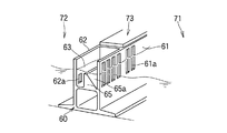
また、図28は、従来の海水交換機能を有する防波堤を示す、一部断面図で表した斜視図であり、前壁61に設けられた海水面の上下に亘って開口した開口部61aと、後壁62に設けられた海水面下に開口する開口部62aとを介して、港外71と港内72の海水に連通する遊水室63を堤体60内に形成した防波堤73において、前記遊水室63内に後壁62に向かって高くなる斜面65aを有する傾斜壁65を設けて、引き波時の外海方向への戻り流れを防止する構成としたものである(特許文献2参照。)。   FIG. 28 is a perspective view showing a breakwater having a conventional seawater exchange function, which is a partial cross-sectional view, and an opening 61a that opens over the seawater surface provided on the front wall 61; In the breakwater 73 formed in the levee body 60 in the breakwater body 63, which is connected to the seawater outside the port 71 and the seawater in the port 72 through the opening 62 a provided in the rear wall 62 that opens below the seawater surface, An inclined wall 65 having an inclined surface 65a that rises toward the rear wall 62 is provided in 63 so as to prevent a return flow in the direction of the open sea during a pulling wave (see Patent Document 2).

また、本件発明者らは、海水を導入する導入口と導入した海水を導出する導水孔を設けた遊水室を有する堤体において、前記導水孔を、その港湾側に面する断面積が遊水室側の断面積より小さいオリフィス形状にすることにより、遊水室側から港湾側へ流出する海水の流量を、港湾側から遊水室側に流入する流量より格段に多くできる海水交換型護岸堤および防波堤を提案している(特許文献3参照。)。   Further, the inventors of the present invention have provided a dike having a water intake chamber provided with an introduction port for introducing seawater and a water introduction hole for deriving the introduced seawater. By making the orifice shape smaller than the cross-sectional area on the side, seawater exchange type seawalls and breakwaters that can significantly increase the flow rate of seawater flowing from the reclaimer side to the harbor side than the flow rate from the harbor side to the reclaimer side are provided. It has been proposed (see Patent Document 3).

しかしながら、上記の海水交換技術は、何れも表層域の海水を底層域に上下方向のみに移送する、いわば一次元的な海水交換技術であるため、護岸や防波堤によって形成される港湾海域内での広範な海水交換を効率的に促進し得ず、前述した港湾内域の水質問題を解消するには不十分であった。
特開2001−159115号公報 特開平9−41341号公報 特開2004−156306号公報
However, all of the above seawater exchange technologies are so-called one-dimensional seawater exchange technologies that transfer surface seawater to the bottom layer only in the vertical direction, so in the sea area of harbors formed by seawalls and breakwaters. Extensive seawater exchange could not be promoted efficiently, and it was insufficient to solve the water quality problems in the harbor area described above.
JP 2001-159115 A JP-A-9-41341 JP 2004-156306 A

従って、本発明の目的は、護岸と防波堤とで形成される港湾海域において、上下方向のみならず当該海域の内海側と外海側との水平方向へ海水を交換せしめて、当該港湾内域の水質を浄化改善することが可能な海水交換型ケーソンを提供することにある。   Therefore, the object of the present invention is to change the water quality in the port inner area by exchanging sea water not only in the vertical direction but also in the horizontal direction between the inner sea side and the outer sea side of the sea area in the port sea area formed by the revetment and the breakwater. It is to provide a seawater exchange type caisson that can improve purification.

前記目的を達成するために、本発明の請求項1に係る海水交換型ケーソンが採用した手段は、衝突する波力により海岸が浸食されるのを保護する護岸と、この護岸から沖合方向に延設され、到来する波を受けて緩和させる防波堤とから形成されてなる海水交換型ケーソンにおいて、前記護岸が、衝突する波力により上昇する海水を、この護岸の前壁面と平行方向の流速成分と、この護岸の前壁面から離れる方向の流速成分とを有する海流に変換する海流変換路を備えた複数の護岸ユニットからなることを特徴とするものである。   In order to achieve the above object, the means adopted by the seawater exchange type caisson according to claim 1 of the present invention is a revetment that protects the coast from being eroded by the wave force of collision, and extends from the revetment in the offshore direction. In the seawater exchange caisson, which is formed from a breakwater that relaxes in response to incoming waves, the seawall rises due to the impacting wave force, and the flow velocity component parallel to the front wall of the seawall The revetment unit is composed of a plurality of revetment units having a current conversion path for converting into a current having a flow velocity component in a direction away from the front wall surface of the revetment.

本発明の請求項2に係る海水交換型ケーソンが採用した手段は、衝突する波力により海岸が浸食されるのを保護する護岸と、この護岸から沖合方向に延設され、到来する波を受けて緩和させる防波堤とから形成されてなる海水交換型ケーソンにおいて、前記防波堤が、外海側から内海側へ流入する海水を、この防波堤の内海側の壁面と平行方向の流速成分と、この防波堤の内海側の壁面から離れる方向の流速成分とを有する海流に変換する海水導入路を備えた複数の防波堤ユニットからなることを特徴とするものである。   The means adopted by the seawater exchange type caisson according to claim 2 of the present invention is a revetment that protects the coast from being eroded by the impacting wave force, and the incoming waves that extend from the revetment in the offshore direction. In the seawater exchange caisson formed by the breakwater to be relaxed, the breakwater causes the seawater flowing from the outer sea side to the inland sea side to flow in a direction parallel to the inner sea wall of the breakwater and the inland sea of the breakwater. It consists of a plurality of breakwater units provided with a seawater introduction path for converting into a sea current having a flow velocity component in a direction away from the side wall surface.

本発明の請求項3に係る海水交換型ケーソンが採用した手段は、衝突する波力により海岸が浸食されるのを保護する護岸と、この護岸から沖合方向に延設され、到来する波を受けて緩和させる防波堤とから形成されてなる海水交換型ケーソンにおいて、前記護岸が、衝突する波力により上昇する海水を、この護岸の前壁面と平行方向の流速成分と、この護岸の前壁面から離れる方向の流速成分とを有する海流に変換する海流変換路を備えた複数の護岸ユニットからなり、かつ前記防波堤は、外海側から内海側へ流入する海水を、この防波堤の内海側の壁面と平行方向の流速成分と、この防波堤の内海側の壁面から離れる方向の流速成分とを有する海流に変換する海水導入路を備えた複数の防波堤ユニットからなることを特徴とするものである。   The means adopted by the seawater exchange type caisson according to claim 3 of the present invention is a revetment that protects the coast from being eroded by the impacting wave force, and an incoming wave that extends from the revetment in the offshore direction. In the seawater exchange type caisson formed by the breakwater to be relaxed, the seawall moves away from the seawater rising by the wave force that collides with the flow velocity component parallel to the front wall of the seawall and the front wall of the seawall The breakwater is composed of a plurality of revetment units having a current conversion path for converting into a current having a flow velocity component in the direction, and the breakwater is parallel to the inland sea wall of the breakwater. And a plurality of breakwater units having a seawater introduction path for converting into a sea current having a flow velocity component in a direction away from the inner sea side wall of the breakwater.

本発明の請求項4に係る海水交換型ケーソンが採用した手段は、請求項1または3のうちの何れか一つの項に記載の海水交換型ケーソンにおいて、前記護岸が、波力により上昇する海水が衝突する背面と、この海水を護岸の前壁面に沿って斜め下方に流下させる傾斜面と、この傾斜面を流下する流れ方向を、護岸の前壁面から離れる方向に変換させる衝突面とからなる海流変換路を、この護岸の壁面の長手方向に沿って設けた複数の護岸ユニットからなることを特徴とするものである。   The means employed by the seawater exchange type caisson according to claim 4 of the present invention is the seawater exchange type caisson according to any one of claims 1 or 3, wherein the seawall rises by wave power. The rear surface where the seawater collides, the inclined surface that causes the seawater to flow obliquely downward along the front wall of the revetment, and the collision surface that converts the flow direction flowing down this inclined surface to a direction away from the front wall of the revetment The ocean current conversion path is composed of a plurality of revetment units provided along the longitudinal direction of the wall surface of the revetment.

本発明の請求項5に係る海水交換型ケーソンが採用した手段は、請求項1または3のうちの何れか一つの項に記載の海水交換型ケーソンにおいて、前記護岸が、波力により上昇する海水が衝突する背面と、この衝突した海水を受け入れる受水部と、受水部に受水した海水を排出口から護岸の前壁面に沿う一方向に流下させる排水口と、この排水口から流下する海水を受ける底面と、底面で受けたこの海水の流れ方向を護岸の前壁面から離れる方向に変換させる衝突面とからなる海流変換路を、この護岸の壁面の長手方向に沿って設けた複数の護岸ユニットからなることを特徴とするものである。   The means adopted by the seawater exchange caisson according to claim 5 of the present invention is the seawater exchange caisson according to any one of claims 1 or 3, wherein the seawall rises by wave power. , The water receiving part that receives the collided seawater, the drain that allows the seawater received by the water receiving part to flow in one direction along the front wall of the revetment, and the water that flows from the drain There are a plurality of ocean current conversion paths that are provided along the longitudinal direction of the wall surface of the revetment, including a bottom surface that receives seawater and a collision surface that transforms the flow direction of the seawater received on the bottom surface away from the front wall surface of the revetment. It consists of a revetment unit.

本発明の請求項6に係る海水交換型ケーソンが採用した手段は、請求項2または3のうちの何れか一つの項に記載の海水交換型ケーソンにおいて、前記防波堤が、外海側の海水を、斜め下方向きであって、かつこの防波堤の内海側の壁面に沿う方向の流速成分を有する方向に向かって、内海側に流入させる海水導入路を設けた複数の防波堤ユニットからなることを特徴とするものである。   Means employed by the seawater exchange caisson according to claim 6 of the present invention is the seawater exchange caisson according to any one of claims 2 or 3, wherein the breakwater is a seawater on the open sea side, It is composed of a plurality of breakwater units provided with seawater introduction passages that flow into the inland side in a direction that is obliquely downward and has a flow velocity component in a direction along the wall of the breakwater on the inland side. Is.

本発明の請求項7に係る海水交換型ケーソンが採用した手段は、請求項2または3のうちの何れか一つの項に記載の海水交換型ケーソンにおいて、前記防波堤が、外海側から上部に打ち上げられた海水を、この防波堤の長手方向に沿って斜め下方に流下させる上部傾斜面と、この上部傾斜面を流下する海水の流れ方向を、防波堤から離れる内海側方向に変換させる衝突面とからなる海水導入路とを、この防波堤の上面の長手方向に沿って設けた複数の防波堤ユニットからなることを特徴とするものである。   The means adopted by the seawater exchange caisson according to claim 7 of the present invention is the seawater exchange caisson according to any one of claims 2 and 3, wherein the breakwater is launched upward from the open sea side. The upper inclined surface that causes the seawater to flow down obliquely downward along the longitudinal direction of the breakwater, and the collision surface that converts the flow direction of the seawater flowing down the upper inclined surface to the inward sea side away from the breakwater The seawater introduction path is composed of a plurality of breakwater units provided along the longitudinal direction of the top surface of the breakwater.

本発明の請求項8に係る海水交換型ケーソンが採用した手段は、請求項7項に記載の海水交換型ケーソンにおいて、前記防波堤が、外海側の海水を、斜め下方向きであって、かつこの防波堤の内海側の壁面に沿う方向の流速成分を有する方向に向かって、内海側に流入させる海水導入路を設けた、複数の防波堤ユニットからなることを特徴とするものである。   The means adopted by the seawater exchange type caisson according to claim 8 of the present invention is the seawater exchange type caisson according to claim 7, wherein the breakwater is directed obliquely downward to the sea water on the outer sea side, and It consists of a plurality of breakwater units provided with a seawater introduction path that flows into the inland sea in a direction having a flow velocity component in a direction along the wall surface on the inland sea side of the breakwater.

本発明の請求項1に係る海水交換型ケーソンによれば、衝突する波力により海岸が浸食されるのを保護する護岸と、この護岸から沖合方向に延設され、到来する波を受けて緩和させる防波堤とから形成されてなる海水交換型ケーソンにおいて、前記護岸が、衝突する波力により上昇する海水を、この護岸の前壁面と平行方向の流速成分と、この護岸の前壁面から離れる方向の流速成分とを有する海流に変換する海流変換路を備えた複数の護岸ユニットからなる構成とすることにより、前記護岸近傍の海域に上下方向のみならず内海側と外海側とを行き交う潮流をも発生せしめて、いわば二次元的な海水交換することが可能となるため、当該港湾海域内の護岸近傍の水質を効果的に浄化改善し得る。   According to the seawater exchange type caisson according to claim 1 of the present invention, the revetment that protects the coast from being eroded by the wave force that collides, and the offshore direction extending from this revetment, mitigates the incoming waves In the seawater exchange caisson formed from the breakwater to be driven, the seawall rises due to the impacting wave force, and the flow velocity component parallel to the front wall of the seawall and the direction away from the front wall of the seawall By comprising a plurality of revetment units equipped with ocean current conversion paths that convert into ocean currents having flow velocity components, not only the vertical direction but also the tidal current that flows between the inland sea side and the outside sea side is generated in the sea area near the revetment. In other words, two-dimensional seawater exchange can be performed, so that the water quality in the vicinity of the seawall in the port sea area can be effectively purified and improved.

また、本発明の請求項2に係る海水交換型ケーソンによれば、衝突する波力により海岸が浸食されるのを保護する護岸と、この護岸から沖合方向に延設され、到来する波を受けて緩和させる防波堤とから形成されてなる海水交換型ケーソンにおいて、前記防波堤が、外海側から内海側へ流入する海水を、この防波堤の内海側の壁面と平行方向の流速成分と、この防波堤の内海側の壁面から離れる方向の流速成分とを有する海流に変換する海水導入路を備えた複数の防波堤ユニットからなる構成とすることにより、前記防波堤近傍の海域に上下方向のみならず内海側と外海側とを行き交う潮流をも発生せしめて、いわば二次元的な海水交換することが可能となるため、当該港湾海域内の防波堤近傍の水質を効果的に浄化改善し得る。   Moreover, according to the seawater exchange type caisson of claim 2 of the present invention, the revetment that protects the coast from being eroded by the impacting wave force, and the incoming wave that extends from the revetment in the offshore direction. In the seawater exchange caisson formed by the breakwater to be relaxed, the breakwater causes the seawater flowing from the outer sea side to the inland sea side to flow in a direction parallel to the inner sea wall of the breakwater and the inland sea of the breakwater. In the sea area in the vicinity of the breakwater, not only in the vertical direction, but also on the inland side and the outside sea side As a result, it is possible to generate two-dimensional seawater exchange, so that the water quality in the vicinity of the breakwater in the port sea area can be effectively purified and improved.

更に、本発明の請求項3に係る海水交換型ケーソンによれば、衝突する波力により海岸が浸食されるのを保護する護岸と、この護岸から沖合方向に延設され、到来する波を受けて緩和させる防波堤とから形成されてなる海水交換型ケーソンにおいて、前記護岸が、衝突する波力により上昇する海水を、この護岸の前壁面と平行方向の流速成分と、この護岸の前壁面から離れる方向の流速成分とを有する海流に変換する海流変換路を備えた複数の護岸ユニットからなり、かつ前記防波堤は、外海側から内海側へ流入する海水を、この防波堤の内海側の壁面と平行方向の流速成分と、この防波堤の内海側の壁面から離れる方向の流速成分とを有する海流に変換する海水導入路を備えた複数の防波堤ユニットからなる構成とすることにより、港湾海域全域に上下方向のみならず前記内海側から外海側に向かう潮流をも発生せしめて、いわば二次元的な海水交換することが可能となるため、当該港湾全域内の水質を効果的に浄化改善し得る。   Furthermore, according to the seawater exchange type caisson according to claim 3 of the present invention, the revetment that protects the coast from being eroded by the impacting wave force, and the incoming waves that extend from the revetment in the offshore direction are received. In the seawater exchange type caisson formed by the breakwater to be relaxed, the seawall moves away from the seawater rising by the wave force of collision with the flow velocity component parallel to the front wall of the seawall and the front wall of the seawall The breakwater is composed of a plurality of revetment units having a current conversion path for converting into a current having a flow velocity component in the direction, and the breakwater is parallel to the inland sea wall of the breakwater. And a plurality of breakwater units having seawater introduction paths for converting into ocean currents having a flow velocity component in a direction away from the inner sea wall of the breakwater. Not only the vertical direction but also the tidal current from the inland sea side to the outside sea side can be generated throughout the entire area, so that two-dimensional seawater exchange is possible, so that the water quality in the entire port area can be effectively purified and improved. obtain.

更にまた、本発明の請求項4および5に係る海水交換型ケーソンによれば、請求項1または3のうちの何れか一つの項に記載の海水交換型ケーソンにおいて、前記護岸が、衝突する波力により上昇する海水を、この護岸の前壁面と平行方向の流速成分と、この護岸の前壁面から離れる方向の流速成分とを有する海流に変換する具体的な海流変換路を備えた複数の護岸ユニットからなるため、前記護岸の長手方向に沿った二次元的な潮流をも実質的に発生せしめることができる。   Furthermore, according to the seawater exchange type caisson according to claims 4 and 5 of the present invention, in the seawater exchange type caisson according to any one of claims 1 or 3, Multiple revetments with specific ocean current conversion paths that convert seawater rising due to force into ocean currents that have a flow velocity component parallel to the front wall of the revetment and a flow velocity component away from the front wall of the revetment Since it consists of units, it is possible to substantially generate a two-dimensional tidal current along the longitudinal direction of the revetment.

あるいは、本発明の請求項6および7に係る海水交換型ケーソンによれば、請求項2または3のうちの何れか一つの項に記載の海水交換型ケーソンにおいて、前記防波堤が、外海側から内海側へ流入する海水を、この防波堤の内海側の壁面と平行方向の流速成分と、この防波堤の内海側の壁面から離れる方向の流速成分とを有する海流に変換する具体的な海水導入路を備えた複数の防波堤ユニットからなるため、前記防波堤の長手方向に沿って内海側から外海側に向かう二次元的な潮流をも実質的に発生せしめることができる。   Alternatively, according to the seawater exchange type caisson according to claims 6 and 7 of the present invention, in the seawater exchange type caisson according to any one of claims 2 and 3, the breakwater is connected from the outside sea side to the inside sea. There is a concrete seawater introduction channel that converts seawater flowing into the seawater into a sea current that has a flow velocity component parallel to the inner sea wall of the breakwater and a flow velocity component away from the inner sea wall of the breakwater. Furthermore, since the breakwater unit is composed of a plurality of breakwater units, it is possible to substantially generate a two-dimensional tidal current from the inner sea side to the outer sea side along the longitudinal direction of the breakwater.

更に、本発明の請求項8に係る海水交換型ケーソンによれば、前記防波堤が、二種類の海水導入路を備えた複数の防波堤ユニットからなる構成とすることにより、前記防波堤の長手方向に沿って内海側から外海側に向かう二次元的な潮流を、より確実に発生せしめ得る。   Furthermore, according to the seawater exchange type caisson according to claim 8 of the present invention, the breakwater is constituted by a plurality of breakwater units having two kinds of seawater introduction paths, so that the breakwater extends along the longitudinal direction of the breakwater. Therefore, it is possible to generate a two-dimensional tidal current from the inland sea to the outside sea more reliably.

以下、本発明に係る海水交換型ケーソンを、その実施の形態を挙げて図1から図19を参照しながら説明する。本発明におけるケーソンとは、護岸ユニットと防波堤ユニットとにより構築される護岸や防波堤を総称して言うものである。
図1は、本発明の海水交換型ケーソンを、港湾の護岸および防波堤に適用した実施の形態として概念的に示す平面図である。図1に示す符号Cは、港湾を構成する海水交換型ケーソンで、この海水交換型ケーソンCは、陸地Gの海岸に複数の護岸ユニット1により構築された護岸Aと、この護岸Aの両端から沖合方向に延設され、複数の防波堤ユニット2により構築された防波堤Bとから形成されている。
Hereinafter, a seawater exchange type caisson according to the present invention will be described with reference to FIGS. The caisson in the present invention is a general term for a seawall and a seawall constructed by a seawall unit and a seawall unit.
FIG. 1 is a plan view conceptually showing an embodiment in which the seawater exchange caisson of the present invention is applied to a seawall and a breakwater in a harbor. The code | symbol C shown in FIG. 1 is the seawater exchange type caisson which comprises a harbor, and this seawater exchange type caisson C is the revetment A constructed | assembled by the revetment unit 1 on the coast of the land G, and both ends of this revetment A It is formed from a breakwater B extending in the offshore direction and constructed by a plurality of breakwater units 2.

即ち、図1において、本発明の実施の形態1に係る海水交換型ケーソンCを形成する護岸Aは、衝突する波力により上昇する海水を、この護岸Aの前壁面3と平行方向の流速成分4と、この護岸Aの前壁面3から離れる方向の流速成分5とを有する海流6に変換する、後述の海流変換路を備えた複数の護岸ユニット1からなり、かつ、海水交換型ケーソンCを形成する防波堤Bは、外海側S1から内海側S2へ流入する海水を、この防波堤Bの内海側の壁面7と平行方向の流速成分8と、この防波堤の内海側の壁面7から離れる方向の流速成分9とを有する海流10に変換する、後述の海水導入路を備えた複数の防波堤ユニット2からなる。 That is, in FIG. 1, the revetment A forming the seawater exchange type caisson C according to the first embodiment of the present invention uses the flow velocity component in the direction parallel to the front wall surface 3 of the revetment A to the seawater rising by the wave force that collides. 4 and a plurality of revetment units 1 having a sea current conversion path, which will be described later, which is converted into a sea current 6 having a flow velocity component 5 in a direction away from the front wall 3 of the revetment A, and a seawater exchange type caisson C The breakwater B to be formed is a direction in which the seawater flowing from the open sea side S 1 to the inland sea side S 2 is separated from the flow velocity component 8 parallel to the inward sea wall 7 of the breakwater B and the inland sea wall 7 of the breakwater. It consists of a plurality of breakwater units 2 provided with a seawater introduction path to be described later.

上記のような構成をなすことによって、護岸Aの前壁面3と平行方向の流速成分4の集合体と、前記防波堤Bの内海側の壁面7と平行方向の流速成分8の集合体とにより、図1に示す如く、各々護岸Aに沿った潮流11と防波堤Bに沿った潮流12を内海側S2に発生させ、上下方向のみならず港湾奥側から外海側S1に向かう潮流を作り出し、水平方向の海水交換を促進して効果的な水質浄化を行うのである。 By configuring as described above, the aggregate of the flow velocity component 4 parallel to the front wall 3 of the revetment A and the aggregate of the flow velocity component 8 parallel to the inner wall 7 of the breakwater B As shown in FIG. 1, a tidal current 11 along the revetment A and a tidal current 12 along the breakwater B are generated on the inland sea side S 2 , creating a tidal current from the harbor back side to the outside sea side S 1 as well as the vertical direction. It promotes horizontal seawater exchange and performs effective water purification.

次に、図2は、本発明の実施の形態1に係る海水交換型ケーソンCを、港湾の護岸および防波堤に適用した他の例として概念的に示す平面図である。即ち、護岸Aを形成する一部の護岸ユニット1の海流変換路、および防波堤Bを形成する一部の防波堤ユニット2の海水導入路の方向が図1の場合と異なっている。その他については、図1と全く同構成であるから、以下その作用についての説明に止めるものとする。   Next, FIG. 2 is a plan view conceptually showing another example in which the seawater exchange caisson C according to Embodiment 1 of the present invention is applied to a seawall and a breakwater in a harbor. That is, the direction of the ocean current conversion path of some revetment units 1 forming the revetment A and the seawater introduction path of some breakwater units 2 forming the breakwater B are different from those in FIG. The rest of the configuration is exactly the same as that shown in FIG.

即ち、衝突する波力により上昇する海水を、その前壁面3と平行方向の流速成分4とその前壁面3から離れる方向の流速成分5とを有する海流6に変換する海流変換路を備えた護岸ユニット1を、前記平行方向の流速成分4を港湾奥側に向かう方向に構成して護岸Aを形成することによって、前記防波堤Bの内海側の壁面7と平行方向の流速成分8の集合体とにより、各々護岸Aに沿った潮流11と防波堤Bに沿った潮流12を内海側S2に発生させ、上下方向のみならず港湾内を反時計回りに内海側S2から外海側S1に向かう潮流11および12を作り出し、水平方向の海水交換を促進して効果的な水質浄化を行うのである。 In other words, the seawall that has the ocean current conversion path that converts the seawater rising by the wave force that collides into the ocean current 6 having the flow velocity component 4 parallel to the front wall surface 3 and the flow velocity component 5 away from the front wall surface 3. By constructing the revetment A by constructing the unit 1 in the direction in which the flow velocity component 4 in the parallel direction is directed toward the back of the harbor, the aggregate of the flow velocity component 8 in the parallel direction with the wall surface 7 on the inner sea side of the breakwater B Causes a tidal current 11 along the revetment A and a tidal current 12 along the breakwater B to be generated on the inland sea side S 2, and not only in the vertical direction but also in the port counterclockwise from the inland sea side S 2 to the outside sea side S 1 . Tidal currents 11 and 12 are created, and horizontal seawater exchange is promoted to effect effective water quality purification.

図1および図2においては、本発明の実施の形態1に係る海水交換型ケーソンCは、本発明に係る海水交換型の護岸Aと本発明に係る海水交換型の防波堤Bとで形成される場合で説明したが、本発明に係る海水交換型ケーソンCは、前記護岸Aもしくは防波堤Bの何れか一方が、従来の護岸もしくは防波堤である組み合わせることもできる。   1 and 2, the seawater exchange type caisson C according to the first embodiment of the present invention is formed by the seawater exchange type revetment A according to the present invention and the seawater exchange type breakwater B according to the present invention. As described in the case, the seawater exchange type caisson C according to the present invention can be combined such that either the revetment A or the breakwater B is a conventional revetment or breakwater.

例えば、図示はしないが、前記海水交換型ケーソンCが、本発明に係る複数の護岸ユニット1からなる護岸Aと従来の防波堤ユニットからなる防波堤Bで形成されている場合は、護岸Aの前壁面3と平行方向の流速成分4の集合体により、護岸Aに沿った潮流11を内海側S2に発生させ、護岸A近傍の内海域で上下方向のみならず外海側S1に向かう潮流を作り出すことにより、水平方向の海水交換も可能となる。 For example, although not shown in the figure, when the seawater exchange caisson C is formed of a seawall A composed of a plurality of seawall units 1 according to the present invention and a seawall B composed of a conventional seawall unit, the front wall surface of the seawall A 3, a tidal current 11 along the revetment A is generated on the inland sea side S 2 , and a tidal current is generated not only in the vertical direction but also on the outside sea side S 1. Accordingly, it is possible to exchange seawater in the horizontal direction.

逆に、前記海水交換型ケーソンCが、従来の複数の護岸ユニットからなる護岸Aと本発明に係る複数の防波堤ユニット2からなる防波堤Bで形成されている場合は、防波堤Bの前壁面7と平行方向の流速成分8の集合体により、防波堤Bに沿った潮流12を内海側S2に発生させ、防波堤近傍の内海域で上下方向のみならず外海側S1に向かう潮流を作り出すことにより、水平方向の海水交換も可能となる。 On the contrary, when the seawater exchange type caisson C is formed by a breakwater A comprising a plurality of conventional breakwater units and a breakwater B comprising a plurality of breakwater units 2 according to the present invention, the front wall surface 7 of the breakwater B and By generating the tidal current 12 along the breakwater B on the inland sea side S 2 by the assembly of the flow velocity component 8 in the parallel direction, and creating the tidal current toward the outside sea side S 1 as well as the vertical direction in the inland sea area near the breakwater, Horizontal seawater exchange is also possible.

即ち、従来の護岸と防波堤とを組み合わせた海水交換型ケーソンでは、表層域の海水を底層域に上下方向のみに移送する、いわば一次元的な海水交換技術であるため、港湾海域内での海水交換を効果的に促進し得なかったが、上記の如く護岸もしくは防波堤の何れかを、本発明に係る海水交換型ケーソンの形態のものとして組み合わせることにより、少なくとも護岸もしくは防波堤の何れか一方の近傍の内海域が、水平方向の海水交換により効果的に水質浄化されるのである。   In other words, the conventional seawater exchange caisson that combines a seawall and a breakwater is a one-dimensional seawater exchange technology that transports surface seawater to the bottom layer only in the vertical direction. Although the exchange could not be effectively promoted, by combining either the seawall or the breakwater as described above in the form of the seawater exchange caisson according to the present invention, at least the vicinity of either the seawall or the breakwater The inland sea area is effectively purified by horizontal seawater exchange.

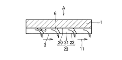
次に、図3乃至図6を参照しながら、本発明の実施の形態1に係る海水交換型ケーソンCの構造を説明する。先ず、実施の形態1に係る海水交換型ケーソンCの前記護岸Aを形成する護岸ユニット1を、前壁面3側から見た斜視図である図3に示す。前記護岸ユニット1は、護岸Aに到来して波力により上昇する海水が衝突する背面20と、この前壁面3に沿って斜め下方に流下させる傾斜面21と、この傾斜面21を流下する流れ方向を、護岸Aの前壁面3から離れる方向に変換させる衝突面22とからなる海流変換路23を、この護岸Aの壁面の長手方向に沿って設けることにより、前述したようにこの護岸Aの前壁面3と平行方向の流速成分と、この護岸Aの前壁面3から離れる方向の流速成分とを有する海流6に変換する作用をなすものである。   Next, the structure of the seawater exchange caisson C according to Embodiment 1 of the present invention will be described with reference to FIGS. 3 to 6. First, FIG. 3 which is the perspective view which looked at the bank protection unit 1 which forms the said bank protection A of the seawater exchange type caisson C which concerns on Embodiment 1 from the front wall surface 3 side is shown. The revetment unit 1 has a rear surface 20 on which seawater rising by wave force collides with the revetment A, an inclined surface 21 that flows down obliquely along the front wall surface 3, and a flow that flows down the inclined surface 21. By providing an ocean current conversion path 23 including a collision surface 22 that changes the direction away from the front wall surface 3 of the revetment A along the longitudinal direction of the wall surface of the revetment A, as described above, It functions to convert into a sea current 6 having a flow velocity component in a direction parallel to the front wall surface 3 and a flow velocity component in a direction away from the front wall surface 3 of the revetment A.

その結果として、前記海流6の護岸Aの前壁面3と平行方向の流速成分により、護岸Aに沿った潮流11が内海側S2に発生する。前記護岸ユニット1の傾斜面21が水平面となす角度θは10〜30度、また海水潮位との位置関係は、傾斜面21と衝突面22との交点Pが平均潮位程度の高さとするのが、本発明の目的とする海水交換の効率上好ましい。 As a result, a tidal current 11 along the revetment A is generated on the inland sea side S 2 due to a flow velocity component parallel to the front wall 3 of the revetment A of the sea current 6. The angle θ between the inclined surface 21 of the revetment unit 1 and the horizontal plane is 10 to 30 degrees, and the positional relationship with the sea tide level is such that the intersection point P between the inclined surface 21 and the collision surface 22 is about the average tide level. From the viewpoint of the efficiency of seawater exchange, which is the object of the present invention, it is preferable.

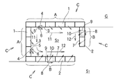
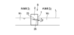
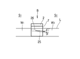
次に、前記防波堤Bを形成する本発明の実施の形態1に係る海水交換型ケーソンCの防波堤ユニット2を、図4から図6に示す。図4は当該防波堤Bの一部を外海側S1から見た正面図、図5は図4を上方向から見た平面図、図6は図4を右方向から見た側面図である。前記防波堤Bをなす防波堤ユニット2は、到来する波の水圧により外海側S1の海水W1を、斜め下方向きであって、かつこの防波堤Bの内海側S2の壁面7に沿う方向の流速成分を有する方向に向かって、内海側S2に海流25として流入させる海水導入路26を設けている。その結果として、前記海流25の防波堤Bの内海側S2の壁面7と平行方向の流速成分の集合体により、防波堤Bに沿った潮流12を発生させる。 Next, the breakwater unit 2 of the seawater exchange type caisson C according to Embodiment 1 of the present invention that forms the breakwater B is shown in FIGS. Figure 4 is a front view of a part of the breakwater B from the open sea side S 1, FIG. 5 is a plan view seen from above FIG. 4, FIG. 6 is a side view of the FIG. 4 from the right. The breakwater unit 2 forming the breakwater B has a flow velocity in the direction along the wall surface 7 of the inner sea side S 2 of the breakwater B in the downward direction of the seawater W 1 on the outer sea side S 1 due to the water pressure of the incoming waves. A seawater introduction path 26 is provided to flow into the inland sea side S 2 as the sea current 25 in the direction having components. As a result, a tidal current 12 along the breakwater B is generated by an aggregate of flow velocity components in a direction parallel to the wall surface 7 of the inland sea side S 2 of the breakwater B of the sea current 25.

図4および図6中の符号Lは海水面を示し、海水導入路26の外海側S1入口高さを干潮時の海水面Lと同程度となるよう、前記防波堤Bの高さを海底の基礎で調整するのが良い。また、海水導入路26の直径は500〜1,000mm、図5において海水導入路26が防波堤Bの内海側S2の壁面7となす角度αは50〜70度、図6において当該海水導入路26が水平面となす角度βは10〜30度とするのが、前記潮流12を発生させて外海側S1と内海側S2との海水を交換させる上で好ましい。 In FIG. 4 and FIG. 6, symbol L indicates the sea level, and the height of the breakwater B is set to the level of the sea bottom so that the sea-side S 1 entrance height of the sea water introduction channel 26 is approximately the same as the sea level L at low tide. It is better to adjust on the basis. Further, the diameter of the seawater introduction path 26 is 500 to 1,000 mm, the angle α between the seawater introduction path 26 and the wall surface 7 of the inland sea side S 2 of the breakwater B in FIG. 5 is 50 to 70 degrees, and the seawater introduction path in FIG. The angle β formed by 26 with respect to the horizontal plane is preferably 10 to 30 degrees in order to exchange the seawater between the open sea side S 1 and the inland sea side S 2 by generating the tidal current 12.

図7は、護岸Aを形成する実施の形態1に係る海水交換型ケーソンCの護岸ユニット1の斜視図2におけるX−X断面を示す平面図、図8,9は、以下に説明する他の実施の形態を示す同一断面部の平面図である。前記実施の形態1においては、図7の平面図に示す如く、当該ユニット1の傾斜面21を流下する海水の流れ方向を、前壁面3から離れる方向の海流6に変換させる衝突面22は、平面図6上背面20に垂直な構成として示したが、図8の平面図に示したように衝突面22と背面20とのなす角度δは、90度を越え、好ましくは図7の場合も含み90〜135度とするのが良い。角度δが90度未満であると、潮流6の平行方向成分が逆方向に向かい、135度を越えると傾斜面21が長くなり過ぎて潮流6が失速してしまう。また、図9の平面図に示すように、衝突面22をある曲率Rを有する円弧状に形成することもできる。   FIG. 7 is a plan view showing the XX cross section in the perspective view 2 of the seawall-exchangeable caisson C according to the first embodiment for forming the seawall A, and FIGS. It is a top view of the same cross section which shows an embodiment. In the first embodiment, as shown in the plan view of FIG. 7, the collision surface 22 for converting the flow direction of the seawater flowing down the inclined surface 21 of the unit 1 into the ocean current 6 in the direction away from the front wall surface 3 is: Although shown as a configuration perpendicular to the rear surface 20 on the plan view 6, the angle δ formed by the collision surface 22 and the rear surface 20 exceeds 90 degrees as shown in the plan view of FIG. 8, preferably also in the case of FIG. 7. Including 90 to 135 degrees is preferable. If the angle δ is less than 90 degrees, the parallel component of the tidal current 6 is directed in the opposite direction, and if it exceeds 135 degrees, the inclined surface 21 becomes too long and the tidal current 6 is stalled. Further, as shown in the plan view of FIG. 9, the collision surface 22 can be formed in an arc shape having a certain curvature R.

次に、図10乃至図13を用いて、以下本発明の実施の形態2について説明する。図10は、図1で示した護岸Aを形成する本発明の実施の形態2に係る海水交換型ケーソンCの護岸ユニットを示した斜視図である。符号1は、前記護岸Aを形成する護岸ユニットを示し、波力により上昇する海水が衝突する背面20と、この衝突した海水を受け入れる受水部30と、受水部30に受水した海水を排出口から護岸の前壁面3に沿う一方向に流下させる排水口31と、この排水口31から流下する海水を受ける底面33と、底面33で受けたこの海水の流れ方向を護岸Aの前壁面3から離れる方向に変換させる衝突面22とからなる海流変換路32を、この護岸Aの壁面の長手方向に沿って設けることにより、この護岸Aの前壁面3と平行方向の流速成分と、この護岸Aの前壁面3から離れる方向の流速成分とを有する海流6に変換する作用をなすものである。   Next, a second embodiment of the present invention will be described below with reference to FIGS. FIG. 10 is a perspective view showing a seawall-exchangeable caisson C revetment unit according to Embodiment 2 of the present invention that forms the revetment A shown in FIG. Reference numeral 1 denotes a revetment unit that forms the revetment A, and includes a rear surface 20 on which seawater rising due to wave forces collides, a water receiving unit 30 that receives the collided seawater, and seawater received by the water receiving unit 30. A drainage port 31 that flows down in one direction along the front wall 3 of the revetment from the discharge port, a bottom surface 33 that receives seawater flowing down from this drainage port 31, and the flow direction of this seawater that is received at the bottom surface 33 indicates the front wall surface of the revetment A 3 is provided along the longitudinal direction of the wall surface of the revetment A to provide a flow velocity component parallel to the front wall 3 of the revetment A, It functions to convert to sea current 6 having a flow velocity component in a direction away from the front wall surface 3 of the revetment A.

更に、図1で示した防波堤Bを形成する本発明の実施の形態2に係る海水交換型ケーソンCの防波堤ユニットについて、図11乃至図13を用いて以下に説明する。図11は防波堤ユニット2を外海側S1から見た正面図、図12は図11を上方向から見た平面図、図13は図11の防波堤Bを右方向から見た側面図を示す。前記防波堤Bは、外海側から上部に打ち上げられた海水を、この防波堤Bの長手方向に沿って斜め下方に流下させる上部傾斜面40と、この上部傾斜面40を流下する海水の流れ方向を、防波堤Bから離れる内海側S2方向に変換させる衝突面41とからなる海水導入路42とを、この防波堤Bの上面の長手方向に沿って設けることにより、この防波堤Bの前壁面7と平行方向の流速成分と、前記防波堤Bの内海側S2の壁面7から離れる方向の流速成分とを有する海流6に変換する作用をなすものである。海流6の前記防波堤Bの内海側S2の壁面7と平行方向の流速成分により、防波堤Bに沿った潮流12を内海側S2に発生させて、外海側S1との海水交換を効率化ならしめる。 Furthermore, the breakwater unit of the seawater exchange type caisson C according to Embodiment 2 of the present invention that forms the breakwater B shown in FIG. 1 will be described below with reference to FIGS. 11 to 13. Figure 11 is a front view of the breakwater unit 2 from the open sea side S 1, FIG. 12 is a plan view seen from above FIG. 11, FIG. 13 shows a side view of the breakwater B of FIG. 11 from the right side. The breakwater B has an upper inclined surface 40 that causes seawater launched upward from the open sea side to flow obliquely downward along the longitudinal direction of the breakwater B, and a flow direction of seawater flowing down the upper inclined surface 40, a seawater inlet passage 42 made Utsumi side S 2 direction converted to impact surface 41. away from breakwater B, by providing along the longitudinal direction of the upper surface of the breakwater B, a direction parallel to the front wall surface 7 of the breakwater B And a flow velocity component in a direction away from the wall surface 7 on the inland sea side S 2 of the breakwater B is converted into the ocean current 6. By the breakwater velocity components of the wall 7 parallel direction Utsumi side S 2 of the B ocean current 6, by generating power flow 12 along the breakwater B Utsumi side S 2, efficient water exchange with the open sea side S 1 Make it smooth.

図11において、防波堤ユニット2の上部傾斜面40が水平面となす角度γは10〜30度、また海水潮位との位置関係は、傾斜面40と衝突面41との交点Qが平均潮位程度の高さとするのが、本発明の目的とする海水交換の効率上好ましい。また、図には示さないが、前記衝突面41が防波堤Bの内海側S2の壁面7となす平面図上の角度は直角である必要はなく、90度未満に傾斜させて、潮流6の壁面7との平行方向の流速成分が大きくなるように構成することもできる。 In FIG. 11, the angle γ between the upper inclined surface 40 of the breakwater unit 2 and the horizontal plane is 10 to 30 degrees, and the positional relationship with the seawater tide level is such that the intersection point Q between the inclined surface 40 and the collision surface 41 is as high as the average tide level. It is preferable from the viewpoint of the efficiency of seawater exchange that is the object of the present invention. Although not shown in the figure, the angle on the plan view that the collision surface 41 forms with the wall surface 7 of the inland sea side S 2 of the breakwater B does not have to be a right angle. The flow velocity component in the direction parallel to the wall surface 7 can be increased.

図14は、護岸Aをなす前記実施の形態2に係る海水交換型ケーソンCの護岸ユニット1の斜視図10におけるY−Y断面を示す平面図、図15、16は、以下に説明する他の実施の形態を示す同一断面部の平面図である。前記実施の形態2においては、図14に示す如く、受水部30に受水した海水を前壁面3から離れる方向の海流6に変換させる衝突面22は、背面20に垂直な構成として示したが、図15の平面図に示したように衝突面22と背面20とのなす角度δを90度を越える角度としても良く、δは図8を用いて説明した場合と同様の理由から、90〜135度とするのが好ましい。また、図16の平面図に示すように、衝突面22をある曲率Rを有する円弧状に形成することもできる。   FIG. 14 is a plan view showing a YY cross section in a perspective view 10 of the seawall-exchangeable caisson C according to the second embodiment forming the seawall A, and FIGS. 15 and 16 are other views described below. It is a top view of the same cross section which shows an embodiment. In the second embodiment, as shown in FIG. 14, the collision surface 22 that converts the seawater received by the water receiving unit 30 into the ocean current 6 in a direction away from the front wall surface 3 is shown as a configuration perpendicular to the back surface 20. However, as shown in the plan view of FIG. 15, the angle δ formed between the collision surface 22 and the back surface 20 may be an angle exceeding 90 degrees, and δ is 90 for the same reason as described with reference to FIG. It is preferable to set it to -135 degrees. Further, as shown in the plan view of FIG. 16, the collision surface 22 can be formed in an arc shape having a certain curvature R.

更に、防波堤Bをなす他の実施の形態に係る海水交換型ケーソンCの防波堤ユニット2を、防波堤Bの一部を外海側S1から見た正面図の図17、図17を上方より見た平面図の図18、図17の右方向から見た側面図の図19に示す。本実施の形態に示す如く、外海側S1から当該ユニット2の上部に打ち上げられた海水を、この防波堤Bの長手方向に沿って斜め下方に流下させる上部傾斜面40と、この上部傾斜面40を流下する海水の流れ方向を、防波堤Bから離れる内海側S2方向に変換させる衝突面41とからなる海水導入路42を、この防波堤Bの上面の長手方向に沿って設けるとともに、外海側S1の海水W1を、斜め下方向きであって、かつこの防波堤Bの内海側S2の壁面7に沿う方向の流速成分を有する方向に向かって、内海側S2に海流25を流入させる海水導入路26を設けることもできる。 Furthermore, FIG. 17 and FIG. 17 of the front view which looked at the breakwater unit 2 of the seawater exchange type caisson C according to another embodiment forming the breakwater B from a part of the breakwater B from the open sea side S 1 were viewed from above. It is shown in FIG. 19 of the side view seen from the right direction of FIG. 18, FIG. 17 of a top view. As shown in the present embodiment, an upper inclined surface 40 that causes seawater launched from the open sea side S 1 to the upper portion of the unit 2 to flow obliquely downward along the longitudinal direction of the breakwater B, and the upper inclined surface 40 the flow direction of the sea water flowing down, the seawater inlet passage 42 made Utsumi side S 2 is converted into the direction impact surface 41. away from breakwater B, provided with the longitudinal direction of the upper surface of the breakwater B, open sea side S 1 seawater W 1 is directed obliquely downward, and seawater 25 flows into the inland sea side S 2 in a direction having a flow velocity component along the wall surface 7 of the breakwater B on the inland sea side S 2. An introduction path 26 can also be provided.

このように、異なる種類の海水導入路26および42を、前記防波堤Bの長手方向に沿って各々設けることにより、防波堤Bの内海側S2の壁面7と平行方向の流速成分の集合体が、防波堤Bに沿った潮流12を内海側S2に発生させて、外海側S1との海水交換をより効果的に可能ならしめる。 Thus, by providing different types of seawater introduction paths 26 and 42 along the longitudinal direction of the breakwater B, the aggregate of flow velocity components parallel to the wall surface 7 of the inland sea side S 2 of the breakwater B is obtained. tide 12 along the breakwater B is generated in Utsumi side S 2, it makes it more effectively allow the water exchange with the open sea side S 1.

以上、本発明に係る海水交換型ケーソンの実施の形態について、陸地Gの海岸に複数の護岸ユニット1により構築された護岸Aと、この護岸Aの両端から沖合方向に延設され、複数の防波堤ユニット2により構築された防波堤Bとから港湾を形成する海水交換型ケーソンCにつき、図1の概念図に則り説明したが、上記実施の形態2において説明した図11乃至13の防波堤Bを、実施の形態1に適用することもできる。また逆に、上記実施の形態1において説明した図4乃至6の防波堤Bを、実施の形態2に適用することも可能であり、護岸Aと防波堤Bとの組み合わせの形態を特に制限するものではない。   As mentioned above, about embodiment of the seawater exchange type caisson according to the present invention, a revetment A constructed by a plurality of revetment units 1 on the coast of land G, and a plurality of breakwaters extending from both ends of the revetment A in the offshore direction. The seawater exchange type caisson C that forms a harbor from the breakwater B constructed by the unit 2 has been described according to the conceptual diagram of FIG. 1, but the breakwater B of FIGS. 11 to 13 described in the second embodiment is implemented. It can also be applied to the first form. Conversely, the breakwater B of FIGS. 4 to 6 described in the first embodiment can be applied to the second embodiment, and the combination of the revetment A and the breakwater B is not particularly limited. Absent.

以上、本発明の請求項1乃至8に係る海水交換型ケーソンによれば、衝突する波力により海岸が浸食されるのを保護する護岸と、この護岸から沖合方向に延設され、到来する波を受けて緩和させる防波堤とから形成されてなる海水交換型ケーソンにおいて、前記護岸が海流変換路を備えた複数の護岸ユニットからなる、あるいは前記防波堤が海水導入路を備えた複数の防波堤ユニットからなる構成としたことにより、護岸や防波堤の壁面と平行方向の流速成分の集合体が、前記護岸あるいは防波堤に沿う潮流を内海側に発生させて、外海側との海水交換を効果的に可能ならしめる。   As described above, according to the seawater exchange type caisson according to claims 1 to 8 of the present invention, the revetment that protects the coast from being eroded by the impacting wave force, and the incoming wave extending from the revetment in the offshore direction. In the seawater exchange type caisson formed by a breakwater that relaxes by receiving, the revetment is composed of a plurality of revetment units equipped with ocean current conversion paths, or the breakwater is composed of a plurality of breakwater units equipped with seawater introduction paths As a result of the configuration, the aggregate of flow velocity components parallel to the walls of the revetment or breakwater generates a tidal current along the revetment or breakwater on the inner sea side, enabling effective seawater exchange with the outer sea side. .

更に、衝突する波力により海岸が浸食されるのを保護する護岸と、この護岸から沖合方向に延設され、到来する波を受けて緩和させる防波堤とから形成されてなる海水交換型ケーソンにおいて、前記護岸が海流変換路を備えた複数の護岸ユニットからなり、かつ前記防波堤が海水導入路を備えた複数の防波堤ユニットからなる構成としたことにより、上下方向のみならず前記内海側から外海側に向かう潮流をも発生せしめて、いわば二次元的な海水交換することが可能となるため、当該港湾海域内の水質が効果的に浄化改善し得る。   Furthermore, in the seawater exchange type caisson formed from a revetment that protects the coast from being eroded by the wave force that collides, and a breakwater that extends from this revetment in the offshore direction and relaxes in response to incoming waves, The revetment is composed of a plurality of revetment units equipped with ocean current conversion paths, and the breakwater is composed of a plurality of breakwater units equipped with seawater introduction paths. It is possible to generate two-dimensional seawater exchange by generating a tidal current, so that the water quality in the port sea area can be effectively purified and improved.

次に、図20乃至22を用いて、本発明の海水交換型ケーソンを形成する護岸の実施例について説明する。図20は、本発明の実施例を示す平面図であって、長さ5m、幅5m、深さ0.5mの平面造波水槽45に水深0.3mの水を張り、図3および図10を用いて説明した本発明に係る護岸Aのモデル46を、図20に示すように水槽45の一端に造波板47に平行になるよう並べ、造波板47により一様な波48を発生させ、丸印で示した電磁流速計Sを用いて図中に示したX方向、即ち、護岸モデル46に平行方向の流速を測定してその効果を確認した。   Next, an embodiment of the revetment that forms the seawater exchange caisson of the present invention will be described with reference to FIGS. FIG. 20 is a plan view showing an embodiment of the present invention, in which water having a depth of 0.3 m is spread on a plane wave-making water tank 45 having a length of 5 m, a width of 5 m, and a depth of 0.5 m. As shown in FIG. 20, the model 46 of the revetment A according to the present invention described with reference to FIG. 20 is arranged at one end of the water tank 45 so as to be parallel to the wave plate 47, and the wave plate 47 generates a uniform wave 48. The effect was confirmed by measuring the flow velocity in the X direction shown in the figure, that is, parallel to the revetment model 46, using the electromagnetic anemometer S indicated by a circle.

使用した護岸モデル46の具体的寸法(mm)は、図21の46aおよび図22の46bに示した通りである。また、比較のため従来の護岸として図27を用いて説明した特開2001−159115号公報に開示されている護岸についても、上記とほぼ同一外形寸法のモデルを作成し同様の実験を行った。発生させた波は、波高7cm、周期1.0s、波長1.56mの規則波である。   Specific dimensions (mm) of the used revetment model 46 are as shown in 46a of FIG. 21 and 46b of FIG. For comparison, a model having substantially the same external dimensions as described above was also created for the revetment disclosed in Japanese Patent Application Laid-Open No. 2001-159115 described with reference to FIG. 27 as a conventional revetment. The generated wave is a regular wave having a wave height of 7 cm, a period of 1.0 s, and a wavelength of 1.56 m.

実験結果を表1に示す。表中の数値は、図20に示した計測位置でのX方向流速の最大値を示している。従来の遊水室下部に導水管を設けただけの図27の護岸モデルでは、X方向の流れがほとんど生じていないが、本発明の護岸モデル46a,46bでは50cm/s前後のX方向の流れが生じていることが分かる。   The experimental results are shown in Table 1. The numerical values in the table indicate the maximum value of the X direction flow velocity at the measurement position shown in FIG. In the conventional revetment model shown in FIG. 27 in which a water guide pipe is provided at the lower part of the water reserving room, there is almost no flow in the X direction. You can see that it has occurred.

Figure 0004336323
Figure 0004336323

次に、図23乃至図25を用いて、本発明の海水交換型ケーソンを形成する防波堤の実施例につき説明する。図23は、本発明の実施例を示す平面図であって、上記と同一の平面造波水槽45に水深0.3mの水を張り、図4〜6および図11〜13を用いて説明した本発明に係る防波堤モデル50を、図23に示すように水槽45のほぼ中央部に造波板47に平行になるよう並べ、造波板47により一様な波48を発生させ、丸印で示した電磁流速計Sを用いて図中に示したX方向、即ち防波堤モデル50に平行方向の流速を測定してその効果を確認した。   Next, an embodiment of a breakwater that forms the seawater exchange caisson of the present invention will be described with reference to FIGS. FIG. 23 is a plan view showing an embodiment of the present invention, in which water having a depth of 0.3 m is applied to the same plane wave-making water tank 45 as described above, and has been described with reference to FIGS. 4 to 6 and FIGS. As shown in FIG. 23, the breakwater model 50 according to the present invention is arranged in a substantially central part of the water tank 45 so as to be parallel to the wavemaking plate 47, and the wavemaking plate 47 generates a uniform wave 48. The effect was confirmed by measuring the flow velocity in the X direction shown in the figure, that is, in the direction parallel to the breakwater model 50, using the electromagnetic current meter S shown.

使用した防波堤モデル50の具体的寸法(mm)は、図24の50aおよび図25の50bに示す通りである。図24の海水導入路51は、直径50mmの貫通孔を、α=60度、β=20度となるよう各ユニットに3個開孔した。また、図25の上部傾斜面が水平面となす角度γは20度として形成した。比較のため、従来の防波堤として図28を用いて説明した特開平9−41341号公報に開示されている防波堤についても、上記とほぼ同一外形寸法のモデルを作成し同様の実験を行った。発生させた波は、上記と同一の波高7cm、周期1.0s、波長1.56mの規則波である。   Specific dimensions (mm) of the used breakwater model 50 are as shown by 50a in FIG. 24 and 50b in FIG. In the seawater introduction passage 51 of FIG. 24, three through holes having a diameter of 50 mm were opened in each unit so that α = 60 degrees and β = 20 degrees. Further, the angle γ formed by the upper inclined surface in FIG. 25 with the horizontal plane was set to 20 degrees. For comparison, a model having substantially the same external dimensions as described above was created for the breakwater disclosed in Japanese Patent Application Laid-Open No. 9-41341 described with reference to FIG. 28 as a conventional breakwater, and the same experiment was performed. The generated wave is a regular wave having the same wave height of 7 cm, period of 1.0 s, and wavelength of 1.56 m as described above.

実験結果を表2に示す。表中の数値は、図23に示した計測位置でのX方向流速の最大値を示している。従来の遊水室内に傾斜壁を設けた防波堤モデルではX方向の流れがほとんど生じていないが、本発明の防波堤モデル50a,50bでは約60cm/sもの流れが生じていることが分かる。   The experimental results are shown in Table 2. The numerical values in the table indicate the maximum value of the X direction flow velocity at the measurement position shown in FIG. In the conventional breakwater model in which an inclined wall is provided in the recreational water chamber, almost no flow in the X direction is generated, but in the breakwater models 50a and 50b of the present invention, a flow of about 60 cm / s is generated.

Figure 0004336323
Figure 0004336323

以上の結果から、護岸と防波堤とで形成されて港湾、漁港等を構成する本発明に係る海水交換型ケーソンによれば、港湾海域の上下方向のみならず護岸および防波堤の長手方向に沿って、内海側から外海側に向かう潮流をも発生せしめて、いわば二次元的な海水交換することが可能となるため、当該港湾海域内の水質を効果的に浄化改善し得る。   From the above results, according to the seawater exchange type caisson according to the present invention, which is formed of a seawall and a breakwater and constitutes a port, a fishing port, etc., not only in the vertical direction of the port sea area but also in the longitudinal direction of the seawall and the breakwater, A tidal current from the inland sea to the outside sea is also generated, so that two-dimensional seawater exchange is possible, so that the water quality in the port sea area can be effectively purified and improved.

護岸と防波堤とで形成されて港湾を構成する本発明に係る海水交換型ケーソンの実施の形態として概念的に示す平面図である。It is a top view which shows notionally as embodiment of the seawater exchange type caisson based on this invention which is formed with a seawall and a breakwater, and comprises a harbor. 護岸と防波堤とで形成されて港湾を構成する本発明に係る海水交換型ケーソンの他の実施の形態として概念的に示す平面図である。It is a top view shown notionally as other embodiments of the seawater exchange type caisson concerning the present invention which is formed with a seawall and a breakwater and constitutes a harbor. 本発明の実施の形態1に係る海水交換型ケーソンの護岸を形成する護岸ユニットの斜視図である。It is a perspective view of the bank protection unit which forms the bank protection of the seawater exchange type caisson concerning Embodiment 1 of the present invention. 本発明の実施の形態1に係る海水交換型ケーソンの防波堤を形成する防波堤ユニットの正面図である。It is a front view of the breakwater unit which forms the breakwater of the seawater exchange type caisson concerning Embodiment 1 of the present invention. 本発明の実施の形態1に係る海水交換型ケーソンの防波堤を形成する防波堤ユニットの平面図である。It is a top view of the breakwater unit which forms the breakwater of the seawater exchange type caisson concerning Embodiment 1 of the present invention. 本発明の実施の形態1に係る海水交換型ケーソンの防波堤を形成する防波堤ユニットの側面図である。It is a side view of the breakwater unit which forms the breakwater of the seawater exchange type caisson concerning Embodiment 1 of the present invention. 図3のX−X断面を示す平面図である。It is a top view which shows the XX cross section of FIG. 本発明の他の実施の形態に係る海水交換型ケーソンの護岸を形成する護岸ユニットを示す、図3のX−X断面部に該当する平面図である。It is a top view applicable to the XX cross-section part of FIG. 3 which shows the bank protection unit which forms the bank protection of the seawater exchange type caisson which concerns on other embodiment of this invention. 本発明の他の実施の形態に係る海水交換型ケーソンの護岸を形成する護岸ユニットを示す、図3のX−X断面部に該当する平面図である。It is a top view applicable to the XX cross-section part of FIG. 3 which shows the bank protection unit which forms the bank protection of the seawater exchange type caisson which concerns on other embodiment of this invention. 本発明の実施の形態2に係る海水交換型ケーソンの護岸を形成する護岸ユニットの斜視図である。It is a perspective view of the bank protection unit which forms the bank protection of the seawater exchange type caisson concerning Embodiment 2 of the present invention. 本発明の実施の形態2に係る海水交換型ケーソンの防波堤を形成する防波堤ユニットの正面図である。It is a front view of the breakwater unit which forms the breakwater of the seawater exchange type caisson concerning Embodiment 2 of the present invention. 本発明の実施の形態2に係る海水交換型ケーソンの防波堤を形成する防波堤ユニットの平面図である。It is a top view of the breakwater unit which forms the breakwater of the seawater exchange type caisson concerning Embodiment 2 of the present invention. 本発明の実施の形態2に係る海水交換型ケーソンの防波堤を形成する防波堤ユニットの側面図である。It is a side view of the breakwater unit which forms the breakwater of the seawater exchange type caisson concerning Embodiment 2 of the present invention. 図10のY−Y断面を示す平面図である。It is a top view which shows the YY cross section of FIG. 本発明の他の実施の形態に係る海水交換型ケーソンの護岸を形成する護岸ユニットを示す、図10のY−Y断面部に該当する平面図である。It is a top view applicable to the YY cross section of FIG. 10 which shows the bank protection unit which forms the bank protection of the seawater exchange type caisson which concerns on other embodiment of this invention. 本発明の他の実施の形態に係る海水交換型ケーソンの護岸を形成する護岸ユニットを示す、図10のY−Y断面部に該当する平面図である。It is a top view applicable to the YY cross section of FIG. 10 which shows the bank protection unit which forms the bank protection of the seawater exchange type caisson which concerns on other embodiment of this invention. 本発明の他の実施の形態に係る海水交換型ケーソンの防波堤を形成する防波堤ユニットの正面図である。It is a front view of the breakwater unit which forms the breakwater of the seawater exchange type caisson which concerns on other embodiment of this invention. 本発明の他の実施の形態に係る海水交換型ケーソンの防波堤を形成する防波堤ユニットの平面図である。It is a top view of the breakwater unit which forms the breakwater of the seawater exchange type caisson which concerns on other embodiment of this invention. 本発明の他の実施の形態に係る海水交換型ケーソンの防波堤を形成する防波堤ユニットの側面図である。It is a side view of the breakwater unit which forms the breakwater of the seawater exchange type caisson which concerns on other embodiment of this invention. 本発明の海水交換型ケーソンに係る護岸の実施例を示す平面図である。It is a top view which shows the Example of the bank protection concerning the seawater exchange type caisson of this invention. 本発明の海水交換型ケーソンに係る護岸の実施例において使用した護岸モデルの寸法を示す斜視図である。It is a perspective view which shows the dimension of the revetment model used in the Example of the revetment which concerns on the seawater exchange type caisson of this invention. 本発明の海水交換型ケーソンに係る護岸の実施例において使用した他の護岸モデルの寸法を示す斜視図である。It is a perspective view which shows the dimension of the other revetment model used in the Example of the revetment which concerns on the seawater exchange type caisson of this invention. 本発明の海水交換型ケーソンに係る防波堤の実施例を示す平面図である。It is a top view which shows the Example of the breakwater which concerns on the seawater exchange type caisson of this invention. 本発明の海水交換型ケーソンに係る防波堤の実施例において使用した防波堤モデルの寸法を示す斜視図である。It is a perspective view which shows the dimension of the breakwater model used in the Example of the breakwater which concerns on the seawater exchange type caisson of this invention. 本発明の海水交換型ケーソンに係る防波堤の実施例において使用した他の防波堤モデルの寸法を示す斜視図である。It is a perspective view which shows the dimension of the other breakwater model used in the Example of the breakwater which concerns on the seawater exchange type caisson of this invention. 海水の密度成層の形成を概念的に示す断面図である。It is sectional drawing which shows notionally formation of the density stratification of seawater. 従来の海水浄化型護岸・岸壁を示す断面図である。It is sectional drawing which shows the conventional seawater purification type revetment and quay. 従来の海水交換機能を有する防波堤を示す、一部を断面図で表した斜視図である。It is the perspective view which represented the breakwater which has the conventional seawater exchange function, and represented a part with sectional drawing.

符号の説明Explanation of symbols

A…護岸, B…防波堤, C…海水交換型ケーソン, G…陸地,
L…海水面, S…電磁流速計, S1…外海側, S2…内海側,
1…外海側S1の海水, W2…内海側S2の海水,
1…護岸ユニット, 2…防波堤ユニット, 3…護岸Aの前壁面,
4…海流6の前壁面3と平行方向の流速成分, 5…海流6の前壁面3から離れる方
向の流速成分, 6,10…海流, 7…防波堤Bの内海側S2の壁面,
8…海流10の壁面7と平行方向の流速成分, 9…海流10の壁面7から離れる方
向の流速成分,
11…護岸Aに沿った潮流, 12…防波堤Bに沿った潮流,
20…背面, 21…傾斜面, 22,41…衝突面, 23,32…海流変換路,
25…海流, 26,42…海水導入路,
30…受水部, 31…排水口, 33…底面, 40…上部傾斜面,
45…平面造波水槽, 46,46a,46b…護岸モデル, 47…造波板,
48…発生波, 49…消波材, 50,50a,50b…防波堤モデル
A ... Seawall, B ... Breakwater, C ... Seawater exchange caisson, G ... Land
L ... sea level, S ... electromagnetic current meter, S 1 ... open sea side, S 2 ... Utsumi side,
W 1 ... Sea water of the open sea side S 1 , W 2 ... Sea water of the inland sea side S 2 ,
1 ... Revetment unit, 2 ... Breakwater unit, 3 ... Front wall of revetment A,
4 ... direction parallel velocity components and front wall 3 of the ocean currents 6, 5 ... the direction of the velocity components away from the front wall 3 of the ocean currents 6, 6,10 ... ocean currents, 7 ... wall Utsumi side S 2 of the breakwater B,
8: Flow velocity component parallel to the wall surface 7 of the ocean current 10 9: Flow velocity component away from the wall surface 7 of the ocean current 10
11 ... Tidal current along revetment A, 12 ... Tidal current along breakwater B,
20 ... Back side, 21 ... Inclined surface, 22, 41 ... Collision surface, 23, 32 ... Current flow conversion path,
25 ... sea current, 26,42 ... seawater introduction channel,
30 ... Water receiving part, 31 ... Drain port, 33 ... Bottom surface, 40 ... Upper inclined surface,
45 ... Plane wave tank, 46, 46a, 46b ... Seawall model, 47 ... Wave plate,
48 ... generated wave, 49 ... wave-dissipating material, 50, 50a, 50b ... breakwater model

Claims (8)

衝突する波力により海岸が浸食されるのを保護する護岸と、この護岸から沖合方向に延設され、到来する波を受けて緩和させる防波堤とから形成されてなる海水交換型ケーソンにおいて、前記護岸が、衝突する波力により上昇する海水を、この護岸の前壁面と平行方向の流速成分と、この護岸の前壁面から離れる方向の流速成分とを有する海流に変換する海流変換路を備えた複数の護岸ユニットからなることを特徴とする海水交換型ケーソン。   In the seawater exchange caisson formed of a revetment that protects the coast from being eroded by the wave force that collides, and a breakwater that extends offshore from this revetment and relaxes in response to incoming waves, the revetment However, there are a plurality of ocean current conversion paths that convert seawater rising due to the impacting wave force into ocean currents having a flow velocity component parallel to the front wall of the revetment and a flow velocity component away from the front wall of the revetment. A seawater exchange caisson characterized by the seawall unit. 衝突する波力により海岸が浸食されるのを保護する護岸と、この護岸から沖合方向に延設され、到来する波を受けて緩和させる防波堤とから形成されてなる海水交換型ケーソンにおいて、前記防波堤が、外海側から内海側へ流入する海水を、この防波堤の内海側の壁面と平行方向の流速成分と、この防波堤の内海側の壁面から離れる方向の流速成分とを有する海流に変換する海水導入路を備えた複数の防波堤ユニットからなることを特徴とする海水交換型ケーソン。   In the seawater exchange caisson formed of a revetment that protects the coast from being eroded by a wave force that collides, and a breakwater that extends offshore from the revetment and relaxes in response to incoming waves, the breakwater However, the introduction of seawater that converts seawater flowing from the open sea side into the inland sea side into a sea current having a flow velocity component parallel to the inner sea wall of the breakwater and a flow velocity component away from the inner sea wall of the breakwater. A seawater exchange caisson comprising a plurality of breakwater units with roads. 衝突する波力により海岸が浸食されるのを保護する護岸と、この護岸から沖合方向に延設され、到来する波を受けて緩和させる防波堤とから形成されてなる海水交換型ケーソンにおいて、前記護岸が、衝突する波力により上昇する海水を、この護岸の前壁面と平行方向の流速成分と、この護岸の前壁面から離れる方向の流速成分とを有する海流に変換する海流変換路を備えた複数の護岸ユニットからなり、かつ前記防波堤は、外海側から内海側へ流入する海水を、この防波堤の内海側の壁面と平行方向の流速成分と、この防波堤の内海側の壁面から離れる方向の流速成分とを有する海流に変換する海水導入路を備えた複数の防波堤ユニットからなることを特徴とする海水交換型ケーソン。   In the seawater exchange caisson formed of a revetment that protects the coast from being eroded by the wave force that collides, and a breakwater that extends from the revetment in the offshore direction and relaxes in response to incoming waves, the revetment However, there are a plurality of ocean current conversion paths that convert seawater rising due to the impacting wave force into ocean currents having a flow velocity component parallel to the front wall of the revetment and a flow velocity component away from the front wall of the revetment. The breakwater is composed of a revetment unit, and the breakwater has a flow velocity component parallel to the inner sea wall of the breakwater and a flow velocity component away from the inner wall of the breakwater. A seawater exchange caisson comprising a plurality of breakwater units equipped with a seawater introduction path for converting into a sea current having 前記護岸が、波力により上昇する海水が衝突する背面と、この海水を護岸の前壁面に沿って斜め下方に流下させる傾斜面と、この傾斜面を流下する流れ方向を、護岸の前壁面から離れる方向に変換させる衝突面とからなる海流変換路を、この護岸の壁面の長手方向に沿って設けた複数の護岸ユニットからなることを特徴とする請求項1または3のうちの何れか一つの項に記載の海水交換型ケーソン。   The revetment has a rear surface where seawater rising by wave force collides, an inclined surface that causes the seawater to flow obliquely downward along the front wall surface of the revetment, and a flow direction that flows down this inclined surface from the front wall surface of the revetment. The ocean current conversion path composed of a collision surface to be converted in a separating direction is composed of a plurality of revetment units provided along the longitudinal direction of the wall surface of the revetment. Sea water exchange type caisson according to item. 前記護岸が、波力により上昇する海水が衝突する背面と、この衝突した海水を受け入れる受水部と、受水部に受水した海水を排出口から護岸の前壁面に沿う一方向に流下させる排水口と、この排水口から流下する海水を受ける底面と、底面で受けたこの海水の流れ方向を護岸の前壁面から離れる方向に変換させる衝突面とからなる海流変換路を、この護岸の壁面の長手方向に沿って設けた複数の護岸ユニットからなることを特徴とする請求項1または3のうちの何れか一つの項に記載の海水交換型ケーソン。   The revetment causes the back surface where seawater rising by wave power collides, a water receiving part that receives the collided seawater, and the seawater received by the water receiving part to flow down in one direction along the front wall of the revetment from the discharge port. An ocean current conversion path comprising a drainage port, a bottom surface for receiving seawater flowing down from the drainage port, and a collision surface for converting the flow direction of the seawater received at the bottom surface away from the front wall surface of the revetment The seawater exchange type caisson according to any one of claims 1 and 3, comprising a plurality of revetment units provided along a longitudinal direction of the seawater. 前記防波堤が、外海側の海水を、斜め下方向きであって、かつこの防波堤の内海側の壁面に沿う方向の流速成分を有する方向に向かって、内海側に流入させる海水導入路を設けた複数の防波堤ユニットからなることを特徴とする請求項2または3のうちの何れか一つの項に記載の海水交換型ケーソン。   A plurality of seawater introduction passages, wherein the breakwater is provided with a seawater introduction path for flowing the seawater on the outer sea side into the inland sea side in a direction obliquely downward and having a flow velocity component in a direction along a wall surface on the inner sea side of the breakwater. The seawater exchange caisson according to any one of claims 2 and 3, wherein the seawater exchange caisson is composed of a breakwater unit. 前記防波堤が、外海側から上部に打ち上げられた海水を、この防波堤の長手方向に沿って斜め下方に流下させる上部傾斜面と、この上部傾斜面を流下する海水の流れ方向を、防波堤から離れる内海側方向に変換させる衝突面とからなる海水導入路とを、この防波堤の上面の長手方向に沿って設けた複数の防波堤ユニットからなることを特徴とする請求項2または3のうちの何れか一つの項に記載の海水交換型ケーソン。   The breakwater has an upper inclined surface that causes seawater launched upward from the open sea side to flow downward obliquely along the longitudinal direction of the breakwater, and the flow direction of seawater that flows down the upper inclined surface is separated from the breakwater. 4. The seawater introduction path comprising a collision surface to be converted in a lateral direction is composed of a plurality of breakwater units provided along the longitudinal direction of the top surface of the breakwater. Seawater exchange caisson according to one of the items. 前記防波堤が、外海側の海水を、斜め下方向きであって、かつこの防波堤の内海側の壁面に沿う方向の流速成分を有する方向に向かって、内海側に流入させる海水導入路を設けた複数の防波堤ユニットからなることを特徴とする請求項7項に記載の海水交換型ケーソン。

A plurality of seawater introduction passages, wherein the breakwater is provided with a seawater introduction path for flowing the seawater on the outer sea side into the inland sea side in a direction obliquely downward and having a flow velocity component in a direction along a wall surface on the inner sea side of the breakwater. The seawater exchange type caisson according to claim 7, comprising a breakwater unit.

JP2005056303A 2005-03-01 2005-03-01 Seawater exchange caisson Expired - Fee Related JP4336323B2 (en)

Priority Applications (1)

Application Number Priority Date Filing Date Title
JP2005056303A JP4336323B2 (en) 2005-03-01 2005-03-01 Seawater exchange caisson

Applications Claiming Priority (1)

Application Number Priority Date Filing Date Title
JP2005056303A JP4336323B2 (en) 2005-03-01 2005-03-01 Seawater exchange caisson

Publications (2)

Publication Number Publication Date
JP2006241751A JP2006241751A (en) 2006-09-14
JP4336323B2 true JP4336323B2 (en) 2009-09-30

Family

ID=37048433

Family Applications (1)

Application Number Title Priority Date Filing Date
JP2005056303A Expired - Fee Related JP4336323B2 (en) 2005-03-01 2005-03-01 Seawater exchange caisson

Country Status (1)

Country Link
JP (1) JP4336323B2 (en)

Also Published As

Publication number Publication date
JP2006241751A (en) 2006-09-14

Similar Documents

Publication Publication Date Title
KR100727285B1 (en) A river ecosystem protective block
KR101366921B1 (en) Guide block for an inflow of sea water
JP4336323B2 (en) Seawater exchange caisson
CN209873694U (en) Device for collecting fish in tail water of hydropower station
JP2557979B2 (en) Method of forming artificial upflow
CN115316327A (en) Wave dissipation flow guide type artificial fish reef
JP3823998B2 (en) Flood control and irrigation system using tidal current generating device by "UTSURO"
JP2006193981A (en) Littoral transport control structure
JP3909343B2 (en) Seawater exchange promotion type breakwater
JP3505156B2 (en) Submerged embankment
JP2000027141A (en) Equipment for leading water to seabed
JP4687901B2 (en) Vertical seawater exchange device
JPH0641934A (en) Submerged breakwater
JP5080614B2 (en) breakwater
JPH0561406B2 (en)
CN218090713U (en) Scour prevention ecological dam structure suitable for extreme condition
JPH08232237A (en) Water-area construction having function of dissipating wave and of promoting inhabitation of aquatic organism
US7404692B2 (en) Breakwater generating structure
CA2310182A1 (en) Arrangement and method for diverting tidal flows in brackish fairways
JP3836042B2 (en) Embankment
JP2000319840A (en) Sea water exchange type breakwater responding to fluctuation in tidal level
JP4924302B2 (en) Structure of entrance and exit of closed sea area and flow condition control method
CN208201812U (en) A kind of diversion tunnel water inlet disappears whirlpool figure
JP4461600B2 (en) Water purification system
JP3883546B2 (en) Pipeline for seawater purification in closed water area and its installation method

Legal Events

Date Code Title Description
A621 Written request for application examination

Free format text: JAPANESE INTERMEDIATE CODE: A621

Effective date: 20070928

A977 Report on retrieval

Free format text: JAPANESE INTERMEDIATE CODE: A971007

Effective date: 20090311

A131 Notification of reasons for refusal

Free format text: JAPANESE INTERMEDIATE CODE: A131

Effective date: 20090331

TRDD Decision of grant or rejection written
A01 Written decision to grant a patent or to grant a registration (utility model)

Free format text: JAPANESE INTERMEDIATE CODE: A01

Effective date: 20090623

A01 Written decision to grant a patent or to grant a registration (utility model)

Free format text: JAPANESE INTERMEDIATE CODE: A01

A61 First payment of annual fees (during grant procedure)

Free format text: JAPANESE INTERMEDIATE CODE: A61

Effective date: 20090626

FPAY Renewal fee payment (event date is renewal date of database)

Free format text: PAYMENT UNTIL: 20120703

Year of fee payment: 3

R150 Certificate of patent or registration of utility model

Ref document number: 4336323

Country of ref document: JP

Free format text: JAPANESE INTERMEDIATE CODE: R150

Free format text: JAPANESE INTERMEDIATE CODE: R150

FPAY Renewal fee payment (event date is renewal date of database)

Free format text: PAYMENT UNTIL: 20130703

Year of fee payment: 4

LAPS Cancellation because of no payment of annual fees