JP4336031B2 - Tension control method for bar rod mill - Google Patents
Tension control method for bar rod mill Download PDFInfo
- Publication number
- JP4336031B2 JP4336031B2 JP2000203200A JP2000203200A JP4336031B2 JP 4336031 B2 JP4336031 B2 JP 4336031B2 JP 2000203200 A JP2000203200 A JP 2000203200A JP 2000203200 A JP2000203200 A JP 2000203200A JP 4336031 B2 JP4336031 B2 JP 4336031B2
- Authority
- JP
- Japan
- Prior art keywords
- rolling
- rolling mill
- roll
- rolled material
- tension
- Prior art date
- Legal status (The legal status is an assumption and is not a legal conclusion. Google has not performed a legal analysis and makes no representation as to the accuracy of the status listed.)
- Expired - Fee Related
Links
Images


Landscapes
- Metal Rolling (AREA)
- Control Of Metal Rolling (AREA)
Description
【0001】
【発明の属する技術分野】
本発明は、棒線材の連続熱間圧延ラインの仕上げ圧延などにおいて、圧延機間の張力を適正範囲に制御するための方法に関するものである。
【0002】
【従来の技術】
棒鋼や鋼線材の連続熱間圧延において、仕上げ圧延での圧延機間の張力が変動すると圧延製品の直径や真円度が変動する。線材の場合は、このほかレーイングヘッドで形成されるリング径が変動し、非同心リング状にしてコンベア上を搬送する際のトラブル原因となり、該コンベア上で熱処理する場合は製品の材質が変動する。さらにコイル集束やコイル結束においてもトラブル原因となる。このため圧延機間の張力制御が必要である。
【0003】
棒線材圧延における従来の張力制御方法としては、圧延機間での圧延材ループ量が一定に維持されるように制御するループ制御が最も一般的に行われている。しかし、レイアウト上、圧延機間の距離が十分確保できない場合や、高速圧延の場合には、ループ制御では圧延機モーターの制御が追従し難く、十分な制御を行うことができない。
【0004】
特許第2789796号公報には、圧延機間での圧延材の脈動を検出して張力制御する装置が提案されている。この技術は、圧延機出側での線材の脈動を撮像装置により検出し、検出した脈動が解消されるように次の圧延機のロール回転速度を制御するものであり、高速ブロックミルの後方にサイジングミルを設置した場合の両ミル間の張力制御が行えるとされている。
【0005】
【発明が解決しようとする課題】
近年、棒鋼や鋼線材などの連続熱間圧延ラインにおいて、仕上げ圧延温度を従来よりも低下することにより圧延製品の材質を改善する技術が開発され、実用化されている。その際、従来の仕上げ圧延最終スタンドの後面に、クーリングトラフとそれに続く圧延機を設置する動向にある。すなわちクーリングトラフで圧延材温度を低下させたのちに、低温圧延可能な新設圧延機で圧延することが行われる。
【0006】
この場合の課題として、特に線材の高速圧延の場合、従来の最終スタンドと新設圧延機の間での張力制御が困難な点があげられる。すなわち上記のようにループ制御は採用できず、また上記公報の技術は、圧延材の脈動と張力とが直接的な関係にはないため、十分な精度が得られるか疑問が残る。
【0007】
そこで本発明が解決しようとする課題は、棒線材熱間圧延ラインの仕上げ圧延などにおいて、圧延機間の距離に関係なく、圧延機間を高速走行する圧延材の張力を適正範囲に高精度で制御することにより、安定操業を達成するとともに圧延製品の寸法不良を解消することである。ここで圧延機とは、単独のロールスタンドで形成されたものに加え、ブロックミルのように複数のロールスタンドで構成されたものも含むものとする。
【0008】
【課題を解決するための手段】
上記課題を解決するための本発明は、前方圧延機と後方圧延機を順に通過させて棒線材を圧延する際、前方圧延機の出側において、圧延材先端が後方圧延機に噛み込む前の圧延材のロールフリー面直径と該圧延材先端が後方圧延機に噛み込んだ直後の圧延材のロールフリー面直径とをそれぞれ測定し、以降の該圧延材について、前記測定した両ロールフリー面直径間の変化量と予め設定した所定値との差が所定範囲内(0を含む)になるように、前方圧延機または/および後方圧延機の回転速度または/およびロール隙を調整することにより、該圧延材における両圧延機間の張力を制御することを特徴とする棒線材圧延機の張力制御方法である。
【0009】
削除
【0010】
削除
【0011】
削除
【0012】
【発明の実施の形態】
本発明法は、図1の例に示すように、圧延材1を、前方圧延機2と後方圧延機3を順に通過させて圧延する際、両圧延機2,3の間での圧延材1の張力を制御する方法である。
本発明は、図1の例のように、前方圧延機2の出側で測寸装置4により圧延材1のロールフリー面直径d1を測定し、該測定値の変化に基づいて圧延機2,3間の張力を制御する。
【0013】
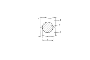
ロールフリー面直径とは、図3のように、圧延ロールに拘束されなかった面の直径である。図3は前方圧延機2の出側の状態であり、図1の圧延ロール7を出たときの圧延材1の直角断面でロールフリー面直径dを示している。なおロールフリー面直径dの測定は、圧延材1をはさんでレーザ投光器および受光器を設けるなどにより行うことができる。また本発明においては、直径dの変化に基づいて制御するので、直径dに相当する値を測定すればよい。ただし、以下の説明では便宜上直径dを用いる。また前方圧延機2出側での測定値をd1 と記す。
【0014】
測寸装置4による圧延材1の先端Fから尾端Tまでのロールフリー面直径d1の変化を模式図に示すと、図4のようになる。すなわち、圧延材1の先端が後方圧延機に噛み込むまでは張力が掛からず直径d1Fであったのが、噛み込んだ後は張力が掛かってd1Mに減少する。このときのd1Fからd1Mへの変化をΔd1Fとする。
【0015】
本発明の張力制御は、圧延材1の先端が後方圧延機3に噛み込んだ直後の、このロールフリー面直径d1の変化Δd1Fに基づいて行う。ここで噛み込んだ直後とは、圧延材1の先端が後方圧延機に噛み込んだ瞬間に前方圧延機のロール出側にあった張力有無の境目となる部位が測寸装置に到達したタイミングを意味するものである。
【0016】
両圧延機2,3間には適正な張力が掛かるように、あらかじめ、前方圧延機2の圧延ロール7および後方圧延機3の圧延ロール8について、回転速度あるいはロール隙が調整してある。このため、圧延材1が後方圧延機3に噛み込むまでは張力が掛からないが、噛み込んだ瞬間に両圧延機2,3間に張力が掛かる。すると、前方圧延機2出側の測寸装置4で測定されるロールフリー面直径d1が、張力なしのときよりΔd1Fだけ小さくなるので、これによって噛み込んだ瞬間を検知することができる。
【0017】
本発明の制御に際しては、図1に示すように、測寸装置4の測定値d1を制御器6に入力し、また所定張力の状態における直径変動Δd1Oをあらかじめ入力しておく。そしてd1の上記変化Δd1Fから、Δd1F−Δd1Oの値を求め、該値に応じて圧延ロール7または8、あるいは圧延ロール7および8の回転速度を調整し、Δd1F−Δd1Oが所定範囲となるように制御する。なお圧延ロール7あるいは8については、ロール隙を調整することもできる。そして、圧延材1が前方圧延機2を抜けるまで制御を続けることができる。
【0018】
削除
【0019】
削除
【0020】
削除
【0021】
削除
【0022】
削除
【0023】
削除
【0024】
削除
【0025】
削除
【0026】
削除
【0027】
削除
【0028】
以上述べた本発明において、対象とする圧延機2,3は、図1および図2に示すような複数対の圧延ロール群からなるもののほか、前方圧延機2、後方圧延機3の一方または双方が1対の圧延ロールからなる場合であってもよい。以上に説明した実施形態により、ループ制御を行わずとも、圧延機間の張力制御を精度よく行うことができる。
【0029】
【実施例】
以下に具体的な操業の一例を示す。鋼線材の連続熱間圧延ラインにおいて、図1に示すような前方圧延機2を最終前圧延機、後方圧延機3を最終圧延機として、両圧延機2,3間の張力制御を行った。両圧延機2,3間の線材寸法は直径9.6mm、線材速度は64m/secである。圧延ロール7と8の間の適正張力は、両ロールの速度比で0.5〜1.5%だけ圧延ロール8を速く回転させる条件とした。
【0030】
この条件における前方圧延機2出側のロールフリー面の測寸装置4における測定値d1の変化量Δd1Oと上記速度比の関係を、あらかじめ求めて制御器6に入力しておいた。
そして実際の圧延において、上記適正張力条件の速度比を制御器6に入力して、該制御器6において、該入力された速度比から所定の変化量Δd 1O を求め、圧延材先端が後方圧延機3に噛み込んだ直後のロールフリー面直径の変化Δd1FからΔd1F−Δd1Oを演算し、この値が0に近付くように圧延ロール7および8の速度を調整して張力制御を行った。
【0031】
圧延結果、線材製品の寸法精度が向上し、1級品の圧延ラインにおける製造歩留まりも向上した。また圧延後のレーイングヘッドで形成されるリング径の変動はなく、非同心リング状にしてコンベア上を搬送する際のトラブルは発生せず、コイル集束やコイル結束においてもトラブルはなかった。さらに、圧延ロールの摩耗が減少し、またミスロールなどのトラブルも生じなかった。
【0032】
【発明の効果】
本発明により、棒線材熱間圧延ラインの仕上げ圧延などにおいて、圧延機間の距離が短い場合でも、圧延機間を高速走行する圧延材の張力を適正範囲に高精度で制御することができ、しかも比較的簡易な設備で容易に制御できる。したがって圧延製品の寸法精度が向上し、1級品の製造歩留まりが向上するほか、圧延後の工程におけるトラブル発生が減少し安定操業が実現される。
【図面の簡単な説明】
【図1】本発明の説明図である。
【図2】本発明におけるロールフリー面直径の説明図である。
【図3】本発明における前方圧延機出側のロールフリー面直径d 1 の変化を示す模式図である。
【符号の説明】
1…圧延材 2…前方圧延機
3…後方圧延機 4…測寸装置
6…制御器 7,8…圧延ロール[0001]
BACKGROUND OF THE INVENTION
The present invention relates to a method for controlling the tension between rolling mills in an appropriate range in finish rolling of a continuous hot rolling line of bar wires.
[0002]
[Prior art]
In continuous hot rolling of steel bars and steel wires, when the tension between rolling mills in finish rolling varies, the diameter and roundness of the rolled product vary. In the case of wire rods, the ring diameter formed by the laying head also fluctuates, causing troubles when transporting on a conveyor in the form of a non-concentric ring, and the product material varies when heat treatment is performed on the conveyor. To do. In addition, it causes trouble in coil focusing and coil bundling. For this reason, tension control between rolling mills is necessary.
[0003]
As a conventional tension control method in rod-and-wire rolling, loop control for controlling the rolling material loop amount between rolling mills to be kept constant is most commonly performed. However, in the layout, when the distance between the rolling mills cannot be ensured sufficiently or in the case of high-speed rolling, the control of the rolling mill motor is difficult to follow in the loop control, and sufficient control cannot be performed.
[0004]
Japanese Patent No. 27899796 proposes an apparatus that detects pulsation of a rolled material between rolling mills and controls tension. This technology detects the pulsation of the wire on the exit side of the rolling mill with an imaging device, and controls the roll rotation speed of the next rolling mill so that the detected pulsation is eliminated. It is said that tension control between both mills can be performed when a sizing mill is installed.
[0005]
[Problems to be solved by the invention]
In recent years, in continuous hot rolling lines such as steel bars and steel wires, a technique for improving the material quality of a rolled product by lowering the finish rolling temperature than before has been developed and put into practical use. At that time, there is a trend to install a cooling trough and subsequent rolling mill on the rear surface of the conventional finish rolling final stand. That is, after lowering the rolling material temperature with a cooling trough, rolling is performed with a new rolling mill capable of low-temperature rolling.
[0006]
As a problem in this case, particularly in the case of high-speed rolling of the wire, it is difficult to control the tension between the conventional final stand and the new rolling mill. That is, as described above, loop control cannot be employed, and the technique disclosed in the above publication does not have a direct relationship between the pulsation and tension of the rolled material.
[0007]
Therefore, the problem to be solved by the present invention is that, in finish rolling of a bar wire hot rolling line, the tension of the rolled material that travels at high speed between the rolling mills with high accuracy within the appropriate range regardless of the distance between the rolling mills. By controlling it, it is possible to achieve stable operation and eliminate dimensional defects in the rolled product. Here, the rolling mill includes not only one formed by a single roll stand but also one constituted by a plurality of roll stands such as a block mill.
[0008]
[Means for Solving the Problems]
The present invention for solving the above-mentioned problems is that when rolling a bar wire by sequentially passing a forward rolling mill and a backward rolling mill, before the rolled material tip bites into the backward rolling mill on the exit side of the forward rolling mill . Measure the roll-free surface diameter of the rolled material and the roll-free surface diameter of the rolled material immediately after the rolled material tip bites into the rear rolling mill. By adjusting the rotational speed or / and the roll gap of the front rolling mill or / and the rear rolling mill so that the difference between the amount of change between and a predetermined value set in advance is within a predetermined range (including 0), A tension control method for a rod and wire rod rolling mill characterized by controlling the tension between both rolling mills in the rolled material.
[0009]
Delete [0010]
Delete [0011]
Delete [0012]
DETAILED DESCRIPTION OF THE INVENTION
In the method of the present invention, as shown in the example of FIG. 1, when rolling the rolled material 1 through the front rolling
In the present invention, as in the example of FIG. 1, the roll-free surface diameter d 1 of the rolled material 1 is measured by the
[0013]
The roll-free surface diameter is the diameter of the surface not restrained by the rolling roll as shown in FIG. FIG. 3 shows a state of the exit side of the front rolling
[0014]
FIG. 4 is a schematic diagram showing the change of the roll free surface diameter d 1 from the front end F to the tail end T of the rolled material 1 by the
[0015]
The tension control of the present invention is performed based on the change Δd 1F of the roll-free surface diameter d 1 immediately after the end of the rolled material 1 is caught in the rear rolling mill 3. Immediately after being bitten here, the timing at which the part that becomes the boundary of the presence or absence of tension on the roll exit side of the front rolling mill at the moment when the tip of the rolled material 1 bites into the rear rolling mill reaches the sizing device. That means.
[0016]
The rotational speed or the roll gap is adjusted in advance for the rolling roll 7 of the front rolling
[0017]
In the control of the present invention, as shown in FIG. 1, enter the measured value d 1 of Hakasun
[0018]
Delete [0019]
Delete [0020]
Delete [0021]
Delete [0022]
Delete [0023]
Delete [0024]
Delete [0025]
Delete [0026]
Delete [0027]
Delete [0028]
Oite the present invention described above, the rolling
[0029]
【Example】
An example of specific operation is shown below. In the continuous hot rolling line for steel wire rods, tension control between the rolling
[0030]
Under this condition, the relationship between the change amount Δd 1O of the measured value d 1 in the
And in the actual rolling, by entering the speed ratio of the proper tension condition to the controller 6, in the controller 6 obtains a predetermined change amount [Delta] d 1O from the speed ratio that is the input, the rolled material tip backward rolling Δd 1F −Δd 1O was calculated from the change Δd 1F in the roll-free surface diameter immediately after being caught in the machine 3, and the tension was controlled by adjusting the speed of the rolling rolls 7 and 8 so that this value approached 0. .
[0031]
As a result of rolling, the dimensional accuracy of the wire product was improved, and the production yield in the first-class rolling line was also improved. Further, there was no fluctuation in the diameter of the ring formed by the laying head after rolling, no trouble occurred when transporting on the conveyor in the form of a non-concentric ring, and there was no trouble in coil focusing or coil binding. Further, the wear of the rolling roll was reduced, and no trouble such as a misroll occurred.
[0032]
【The invention's effect】
According to the present invention, in the finish rolling of the bar wire hot rolling line, even when the distance between the rolling mills is short, the tension of the rolling material traveling at a high speed between the rolling mills can be controlled with high accuracy within an appropriate range. Moreover, it can be easily controlled with relatively simple equipment. Accordingly, the dimensional accuracy of the rolled product is improved, the production yield of the first grade product is improved, and the occurrence of troubles in the process after rolling is reduced, thereby realizing stable operation.
[Brief description of the drawings]
FIG. 1 is an explanatory diagram of the present invention .
FIG. 2 is an explanatory diagram of a roll-free surface diameter in the present invention.
FIG. 3 is a schematic diagram showing a change in roll-free surface diameter d 1 on the exit side of the front rolling mill in the present invention .
[Explanation of symbols]
DESCRIPTION OF SYMBOLS 1 ...
Claims (1)
Priority Applications (1)
| Application Number | Priority Date | Filing Date | Title |
|---|---|---|---|
| JP2000203200A JP4336031B2 (en) | 2000-07-05 | 2000-07-05 | Tension control method for bar rod mill |
Applications Claiming Priority (1)
| Application Number | Priority Date | Filing Date | Title |
|---|---|---|---|
| JP2000203200A JP4336031B2 (en) | 2000-07-05 | 2000-07-05 | Tension control method for bar rod mill |
Publications (2)
| Publication Number | Publication Date |
|---|---|
| JP2002018508A JP2002018508A (en) | 2002-01-22 |
| JP4336031B2 true JP4336031B2 (en) | 2009-09-30 |
Family
ID=18700632
Family Applications (1)
| Application Number | Title | Priority Date | Filing Date |
|---|---|---|---|
| JP2000203200A Expired - Fee Related JP4336031B2 (en) | 2000-07-05 | 2000-07-05 | Tension control method for bar rod mill |
Country Status (1)
| Country | Link |
|---|---|
| JP (1) | JP4336031B2 (en) |
-
2000
- 2000-07-05 JP JP2000203200A patent/JP4336031B2/en not_active Expired - Fee Related
Also Published As
| Publication number | Publication date |
|---|---|
| JP2002018508A (en) | 2002-01-22 |
Similar Documents
| Publication | Publication Date | Title |
|---|---|---|
| JP5096156B2 (en) | Process and equipment for continuous production of thin metal strips | |
| JP5305829B2 (en) | Wire rod rolling method | |
| JPH05277504A (en) | Method and apparatus for guiding rod to slitter station | |
| JP2006289436A (en) | Wire rolling method | |
| KR20200110795A (en) | Casting piece manufacturing method and continuous casting equipment | |
| JP4336031B2 (en) | Tension control method for bar rod mill | |
| JP5775378B2 (en) | Strip rolling method | |
| JP2001246413A (en) | Device and method for cooling hot steel strip | |
| JPS61249614A (en) | Method and device for controlling size of rolling product | |
| JP2008036686A (en) | Method of rolling rolled stock of bar steel | |
| JP4050897B2 (en) | Steel material tracking method and apparatus in continuous rolling | |
| JP3869332B2 (en) | Strip rolling method | |
| JP2003136108A (en) | Hot rolling system and method for threading run out table and method for manufacturing rolled plate | |
| JPH0796124B2 (en) | Meandering control method and controller in hot continuous finishing mill | |
| US8375760B2 (en) | Making and coiling rod and wire | |
| JP3591409B2 (en) | Cooling apparatus for hot-rolled steel strip and cooling method | |
| JP2002520159A (en) | Method and apparatus for controlling a rolling mill | |
| JP3698088B2 (en) | Manufacturing method of hot-rolled steel strip | |
| JPS591015A (en) | Controlling device of rolling | |
| TW550127B (en) | A method and a device for controlling a rolling mill | |
| JP2650549B2 (en) | Winding method of steel strip | |
| JP4065251B2 (en) | Hot finish rolling method that prevents drawing wrinkles | |
| JP3291257B2 (en) | Hot rolled wire rod manufacturing equipment | |
| JP3334784B2 (en) | Continuous joining method of billets in continuous hot rolling | |
| KR20230077729A (en) | Processes and devices for producing metallurgical products, especially of the merchant type, especially in endless mode |
Legal Events
| Date | Code | Title | Description |
|---|---|---|---|
| A621 | Written request for application examination |
Free format text: JAPANESE INTERMEDIATE CODE: A621 Effective date: 20061113 |
|
| A977 | Report on retrieval |
Free format text: JAPANESE INTERMEDIATE CODE: A971007 Effective date: 20081008 |
|
| A131 | Notification of reasons for refusal |
Free format text: JAPANESE INTERMEDIATE CODE: A131 Effective date: 20090324 |
|
| A521 | Written amendment |
Free format text: JAPANESE INTERMEDIATE CODE: A523 Effective date: 20090522 |
|
| TRDD | Decision of grant or rejection written | ||
| A01 | Written decision to grant a patent or to grant a registration (utility model) |
Free format text: JAPANESE INTERMEDIATE CODE: A01 Effective date: 20090623 |
|
| A01 | Written decision to grant a patent or to grant a registration (utility model) |
Free format text: JAPANESE INTERMEDIATE CODE: A01 |
|
| A61 | First payment of annual fees (during grant procedure) |
Free format text: JAPANESE INTERMEDIATE CODE: A61 Effective date: 20090626 |
|
| FPAY | Renewal fee payment (event date is renewal date of database) |
Free format text: PAYMENT UNTIL: 20120703 Year of fee payment: 3 |
|
| R151 | Written notification of patent or utility model registration |
Ref document number: 4336031 Country of ref document: JP Free format text: JAPANESE INTERMEDIATE CODE: R151 |
|
| FPAY | Renewal fee payment (event date is renewal date of database) |
Free format text: PAYMENT UNTIL: 20120703 Year of fee payment: 3 |
|
| FPAY | Renewal fee payment (event date is renewal date of database) |
Free format text: PAYMENT UNTIL: 20130703 Year of fee payment: 4 |
|
| FPAY | Renewal fee payment (event date is renewal date of database) |
Free format text: PAYMENT UNTIL: 20130703 Year of fee payment: 4 |
|
| S531 | Written request for registration of change of domicile |
Free format text: JAPANESE INTERMEDIATE CODE: R313531 |
|
| FPAY | Renewal fee payment (event date is renewal date of database) |
Free format text: PAYMENT UNTIL: 20130703 Year of fee payment: 4 |
|
| R350 | Written notification of registration of transfer |
Free format text: JAPANESE INTERMEDIATE CODE: R350 |
|
| S533 | Written request for registration of change of name |
Free format text: JAPANESE INTERMEDIATE CODE: R313533 |
|
| R350 | Written notification of registration of transfer |
Free format text: JAPANESE INTERMEDIATE CODE: R350 |
|
| LAPS | Cancellation because of no payment of annual fees |